DE102020119864A1 - conductor terminal - Google Patents
conductor terminal Download PDFInfo
- Publication number
- DE102020119864A1 DE102020119864A1 DE102020119864.7A DE102020119864A DE102020119864A1 DE 102020119864 A1 DE102020119864 A1 DE 102020119864A1 DE 102020119864 A DE102020119864 A DE 102020119864A DE 102020119864 A1 DE102020119864 A1 DE 102020119864A1
- Authority
- DE
- Germany
- Prior art keywords
- conductor
- clamping
- actuating
- connection terminal
- terminal
- Prior art date
- Legal status (The legal status is an assumption and is not a legal conclusion. Google has not performed a legal analysis and makes no representation as to the accuracy of the status listed.)
- Pending
Links
Images


Classifications
-
- H—ELECTRICITY
- H01—ELECTRIC ELEMENTS
- H01R—ELECTRICALLY-CONDUCTIVE CONNECTIONS; STRUCTURAL ASSOCIATIONS OF A PLURALITY OF MUTUALLY-INSULATED ELECTRICAL CONNECTING ELEMENTS; COUPLING DEVICES; CURRENT COLLECTORS
- H01R13/00—Details of coupling devices of the kinds covered by groups H01R12/70 or H01R24/00 - H01R33/00
- H01R13/58—Means for relieving strain on wire connection, e.g. cord grip, for avoiding loosening of connections between wires and terminals within a coupling device terminating a cable
- H01R13/5804—Means for relieving strain on wire connection, e.g. cord grip, for avoiding loosening of connections between wires and terminals within a coupling device terminating a cable comprising a separate cable clamping part
- H01R13/5812—Means for relieving strain on wire connection, e.g. cord grip, for avoiding loosening of connections between wires and terminals within a coupling device terminating a cable comprising a separate cable clamping part the cable clamping being achieved by mounting the separate part on the housing of the coupling device
-
- H—ELECTRICITY
- H01—ELECTRIC ELEMENTS
- H01R—ELECTRICALLY-CONDUCTIVE CONNECTIONS; STRUCTURAL ASSOCIATIONS OF A PLURALITY OF MUTUALLY-INSULATED ELECTRICAL CONNECTING ELEMENTS; COUPLING DEVICES; CURRENT COLLECTORS
- H01R4/00—Electrically-conductive connections between two or more conductive members in direct contact, i.e. touching one another; Means for effecting or maintaining such contact; Electrically-conductive connections having two or more spaced connecting locations for conductors and using contact members penetrating insulation
- H01R4/28—Clamped connections, spring connections
- H01R4/48—Clamped connections, spring connections utilising a spring, clip, or other resilient member
- H01R4/4809—Clamped connections, spring connections utilising a spring, clip, or other resilient member using a leaf spring to bias the conductor toward the busbar
- H01R4/4828—Spring-activating arrangements mounted on or integrally formed with the spring housing
- H01R4/4833—Sliding arrangements, e.g. sliding button
-
- H—ELECTRICITY
- H01—ELECTRIC ELEMENTS
- H01R—ELECTRICALLY-CONDUCTIVE CONNECTIONS; STRUCTURAL ASSOCIATIONS OF A PLURALITY OF MUTUALLY-INSULATED ELECTRICAL CONNECTING ELEMENTS; COUPLING DEVICES; CURRENT COLLECTORS
- H01R4/00—Electrically-conductive connections between two or more conductive members in direct contact, i.e. touching one another; Means for effecting or maintaining such contact; Electrically-conductive connections having two or more spaced connecting locations for conductors and using contact members penetrating insulation
- H01R4/28—Clamped connections, spring connections
- H01R4/48—Clamped connections, spring connections utilising a spring, clip, or other resilient member
- H01R4/4809—Clamped connections, spring connections utilising a spring, clip, or other resilient member using a leaf spring to bias the conductor toward the busbar
- H01R4/4828—Spring-activating arrangements mounted on or integrally formed with the spring housing
- H01R4/4835—Mechanically bistable arrangements, e.g. locked by the housing when the spring is biased
-
- H—ELECTRICITY
- H01—ELECTRIC ELEMENTS
- H01R—ELECTRICALLY-CONDUCTIVE CONNECTIONS; STRUCTURAL ASSOCIATIONS OF A PLURALITY OF MUTUALLY-INSULATED ELECTRICAL CONNECTING ELEMENTS; COUPLING DEVICES; CURRENT COLLECTORS
- H01R4/00—Electrically-conductive connections between two or more conductive members in direct contact, i.e. touching one another; Means for effecting or maintaining such contact; Electrically-conductive connections having two or more spaced connecting locations for conductors and using contact members penetrating insulation
- H01R4/28—Clamped connections, spring connections
- H01R4/48—Clamped connections, spring connections utilising a spring, clip, or other resilient member
- H01R4/4809—Clamped connections, spring connections utilising a spring, clip, or other resilient member using a leaf spring to bias the conductor toward the busbar
- H01R4/48185—Clamped connections, spring connections utilising a spring, clip, or other resilient member using a leaf spring to bias the conductor toward the busbar adapted for axial insertion of a wire end
- H01R4/4819—Clamped connections, spring connections utilising a spring, clip, or other resilient member using a leaf spring to bias the conductor toward the busbar adapted for axial insertion of a wire end the spring shape allowing insertion of the conductor end when the spring is unbiased
- H01R4/4821—Single-blade spring
-
- H—ELECTRICITY
- H01—ELECTRIC ELEMENTS
- H01R—ELECTRICALLY-CONDUCTIVE CONNECTIONS; STRUCTURAL ASSOCIATIONS OF A PLURALITY OF MUTUALLY-INSULATED ELECTRICAL CONNECTING ELEMENTS; COUPLING DEVICES; CURRENT COLLECTORS
- H01R4/00—Electrically-conductive connections between two or more conductive members in direct contact, i.e. touching one another; Means for effecting or maintaining such contact; Electrically-conductive connections having two or more spaced connecting locations for conductors and using contact members penetrating insulation
- H01R4/28—Clamped connections, spring connections
- H01R4/48—Clamped connections, spring connections utilising a spring, clip, or other resilient member
- H01R4/4809—Clamped connections, spring connections utilising a spring, clip, or other resilient member using a leaf spring to bias the conductor toward the busbar
- H01R4/4846—Busbar details
- H01R4/4852—Means for improving the contact with the conductor, e.g. uneven wire-receiving surface
-
- H—ELECTRICITY
- H01—ELECTRIC ELEMENTS
- H01R—ELECTRICALLY-CONDUCTIVE CONNECTIONS; STRUCTURAL ASSOCIATIONS OF A PLURALITY OF MUTUALLY-INSULATED ELECTRICAL CONNECTING ELEMENTS; COUPLING DEVICES; CURRENT COLLECTORS
- H01R9/00—Structural associations of a plurality of mutually-insulated electrical connecting elements, e.g. terminal strips or terminal blocks; Terminals or binding posts mounted upon a base or in a case; Bases therefor
- H01R9/22—Bases, e.g. strip, block, panel
- H01R9/24—Terminal blocks
- H01R9/2491—Terminal blocks structurally associated with plugs or sockets
Landscapes
- Connections Arranged To Contact A Plurality Of Conductors (AREA)
Abstract
Die Erfindung betrifft eine Leiteranschlussklemme (1) mit einem Isolierstoffgehäuse (2), wobei das Isolierstoffgehäuse (2) eine Leitereinführungsöffnung (3) zum Einführen eines elektrischen Leiters in einer Leitereinführungsrichtung (L) hat, mit einer Stromschiene (4) und mit einer Klemmfeder (5), wobei die Klemmfeder (5) einen Klemmschenkel (5c) hat, der mit der Stromschiene (4) eine Klemmstelle (6) für den elektrischen Leiter bildet, und mit einem Betätigungselement (7), wobei das Betätigungselement (7) verschiebbar in dem Isolierstoffgehäuse (2) gelagert ist und einen Betätigungsabschnitt (7a) hat, wobei der Betätigungsabschnitt (7a) zum Öffnen der Klemmstelle (6) ausgebildet ist, wobei der Betätigungsabschnitt (7a) derart mit dem Klemmschenkel (5c) in Wechselwirkung steht, dass der Betätigungsabschnitt (5c) zum Öffnen der Klemmstelle (6) an dem Klemmschenkel (5c) anliegt. Der Betätigungsabschnitt (7a) ist dabei auf einer Rastkontur (8) des Isolierstoffgehäuses (2) verschiebbar gelagert.The invention relates to a conductor connection terminal (1) with an insulating material housing (2), the insulating material housing (2) having a conductor entry opening (3) for inserting an electrical conductor in a conductor entry direction (L), with a conductor rail (4) and with a clamping spring ( 5), the clamping spring (5) having a clamping leg (5c) which, together with the busbar (4), forms a clamping point (6) for the electrical conductor, and having an actuating element (7), the actuating element (7) being displaceable in is mounted in the insulating material housing (2) and has an actuating section (7a), the actuating section (7a) being designed to open the clamping point (6), the actuating section (7a) interacting with the clamping leg (5c) in such a way that the Actuating section (5c) for opening the clamping point (6) rests against the clamping leg (5c). The actuating section (7a) is slidably mounted on a latching contour (8) of the insulating housing (2).
Description
Die Erfindung betrifft eine Leiteranschlussklemme mit einem Isolierstoffgehäuse, wobei das Isolierstoffgehäuse eine Leitereinführungsöffnung zum Einführen eines elektrischen Leiters in einer Leitereinführungsrichtung hat, mit einer Stromschiene und mit einer Klemmfeder, wobei die Klemmfeder einen Klemmschenkel hat, der mit der Stromschiene eine Klemmstelle für den elektrischen Leiter bildet, und mit einem Betätigungselement, wobei das Betätigungselement verschiebbar in dem Isolierstoffgehäuse gelagert ist und einen Betätigungsabschnitt hat, wobei der Betätigungsabschnitt zum Öffnen der Klemmstelle ausgebildet ist, wobei der Betätigungsabschnitt derart mit dem Klemmschenkel in Wechselwirkung steht, dass der Betätigungsabschnitt zum Öffnen der Klemmstelle an dem Klemmschenkel anliegt.The invention relates to a conductor connection terminal with an insulating material housing, the insulating material housing having a conductor insertion opening for inserting an electrical conductor in a conductor insertion direction, with a busbar and with a clamping spring, the clamping spring having a clamping leg which, together with the busbar, forms a clamping point for the electrical conductor , and with an actuating element, the actuating element being movably mounted in the insulating material housing and having an actuating section, the actuating section being designed to open the clamping point, the actuating section interacting with the clamping leg in such a way that the actuating section to open the clamping point on the clamping leg is applied.
Ausgehend hiervon ist es Aufgabe der vorliegenden Erfindung eine verbesserte Leiteranschlussklemme zu schaffen.Proceeding from this, it is the object of the present invention to create an improved conductor connection terminal.
Die Aufgabe wird mit einer Leiteranschlussklemme mit den Merkmalen des Anspruchs 1 gelöst. Vorteilhafte Ausführungsformen sind in den Unteransprüchen beschrieben.The object is achieved with a conductor terminal with the features of
Bei der gattungsgemäßen Leiteranschlussklemme wird vorgeschlagen, dass der Betätigungsabschnitt auf einer Rastkontur des Isolierstoffgehäuses verschiebbar gelagert ist.In the case of the conductor connection terminal of the generic type, it is proposed that the actuation section be slidably mounted on a latching contour of the insulating material housing.
Auf diese Weise kann ein verbesserter Betätigungsmechanismus für eine Leiteranschlussklemme bereitgestellt werden. Der Betätigungsabschnitt liegt dabei zum Öffnen der Klemmstelle an dem Klemmschenkel der Klemmfeder an, wobei der Klemmschenkel derart verlagert wird, dass die Klemmstelle bei einer vollständigen Betätigung des Betätigungselementes geöffnet ist. Dabei wirkt eine Federkraft des Klemmschenkels auf den Betätigungsabschnitt des Betätigungselementes.In this way, an improved actuation mechanism for a conductor terminal can be provided. To open the clamping point, the actuating section bears against the clamping limb of the clamping spring, with the clamping limb being displaced in such a way that the clamping point is opened when the actuating element is fully actuated. A spring force of the clamping leg acts on the actuating section of the actuating element.
Die Rastkontur ist zum Beispiel ein Materialvorsprung, der einstückig aus dem Isolierstoffgehäuse gebildet ist. Es ist aber auch denkbar, dass die Rastkontur aus einem separaten Bauteil gebildet und in das Isolierstoffgehäuse eingefügt ist. Der Betätigungsabschnitt liegt dabei auf der Rastkontur auf, wobei der Betätigungsabschnitt während der Verschiebung des Betätigungselementes zum Öffnen der Klemmstelle auf der Rastkontur entlang geführt wird. Die Rastkontur erstreckt sich somit insbesondere von einer Ausgangsstellung des Betätigungselementes, in der die Klemmstelle geschlossen ist, zu einer Betätigungsstellung des Betätigungselementes, in der die Klemmstelle geöffnet ist, so dass der Betätigungsabschnitt zum Öffnen der Klemmstelle auf der Rastkontur führbar ist. Der Betätigungsabschnitt ist somit insbesondere zwischen der Ausgangsstellung und der Betätigungsstellung auf der Rastkontur aufgelagert.The latching contour is, for example, a material projection that is formed in one piece from the insulating material housing. However, it is also conceivable that the latching contour is formed from a separate component and is inserted into the insulating material housing. The actuating section rests on the latching contour, with the actuating section being guided along the latching contour during the displacement of the actuating element to open the clamping point. The latching contour thus extends in particular from an initial position of the actuating element, in which the clamping point is closed, to an actuating position of the actuating element, in which the clamping point is open, so that the actuating section can be guided on the latching contour to open the clamping point. The actuating section is thus supported on the latching contour in particular between the initial position and the actuating position.
Die Ausgangsstellung ist dabei die Position, in der sich das Betätigungselement bei vollständig geschlossener Klemmstelle befindet. Die Betätigungsstellung ist die Position, in der sich das Betätigungselement bei vollständig geöffneter Klemmstelle befindet.The starting position is the position in which the actuating element is located when the clamping point is completely closed. The operating position is the position in which the operating element is when the clamping point is fully open.
Es ist denkbar, dass bei geöffneter Klemmstelle der Betätigungsabschnitt durch die Federkraft an die Rastkontur geklemmt wird, wobei das Betätigungselement bei geöffneter Klemmstelle an der Rastkontur verrastet. Eine derartige Verrastung kann zum Beispiel durch ein Betätigungswerkzeug wieder gelöst werden, indem das Betätigungselement entgegen der Federkraft des Klemmschenkels aus der Verrastung geführt wird. Dabei ist es möglich, dass durch die Federkraft des Klemmschenkels das Betätigungselement automatisch zurück in die Ausgangsstellung verlagerbar ist, sobald das Betätigungselement aus der Verrastung geführt wurde.It is conceivable that when the clamping point is open, the actuating section is clamped to the latching contour by the spring force, with the actuating element latching onto the latching contour when the clamping point is open. Such a latching can be released again, for example, by an actuating tool, in that the actuating element is guided out of the latching against the spring force of the clamping leg. It is possible here for the actuating element to be automatically shiftable back into the starting position by the spring force of the clamping leg as soon as the actuating element has been guided out of the latching position.
Verschiebbar bedeutet insbesondere, dass das Betätigungselement linear verschieblich in dem Isolierstoffgehäuse angeordnet ist. Die Öffnung der Klemmstelle erfolgt damit durch eine lineare Verschiebung des Betätigungselementes von der Ausgangsstellung in die Betätigungsstellung und nicht durch verschwenken des Betätigungselementes um eine Drehachse wie zum Beispiel bei einem Betätigungshebel. Kleinere Kippbewegungen des Betätigungselementes um einen Auflager- oder Drehpunkt sind dennoch möglich, so dass das Betätigungselement zum Beispiel in eine Rastposition überführt werden kann.Displaceable means in particular that the actuating element is arranged in a linearly displaceable manner in the insulating material housing. The clamping point is thus opened by a linear displacement of the actuating element from the initial position into the actuating position and not by pivoting the actuating element about a rotation axis, as is the case, for example, with an actuating lever. Smaller tilting movements of the actuating element about a support or pivot point are nevertheless possible, so that the actuating element can be transferred, for example, into a latching position.
Der Betätigungsabschnitt kann in einer Offenstellung der Klemmstelle zwischen dem Klemmschenkel und der Rastkontur angeordnet sein.When the clamping point is in an open position, the actuating section can be arranged between the clamping leg and the latching contour.
Auf diese Weise kann in der Betätigungsstellung des Betätigungselementes die Federkraft der Klemmfeder, insbesondere des Klemmschenkels der Klemmfeder, auf das Betätigungselement wirken, wobei die Federkraft der Klemmfeder das Betätigungselement an die Rastkontur drücken kann. Somit kann das Betätigungselement in der Betätigungsstellung selbsthaltend festgelegt werden.In this way, when the actuating element is in the actuating position, the spring force of the clamping spring, in particular of the clamping leg of the clamping spring, can act on the actuating element, with the spring force of the clamping spring being able to press the actuating element against the latching contour. The actuating element can thus be fixed in a self-retaining manner in the actuating position.
Die Rastkontur kann als längliche Führungsschiene ausgebildet sein, wobei die längliche Führungsschiene einen Höhenversatz hat.The latching contour can be designed as an elongate guide rail, with the elongate guide rail being offset in height.
Der Betätigungsabschnitt kann entlang der länglichen Führungsschiene während des gesamten Öffnungsvorganges der Klemmstelle auf der Führungsschiene geführt werden, wobei der Betätigungsabschnitt nach Erreichen der Betätigungsstellung, in der die Klemmstelle geöffnet ist, durch den Höhenversatz der Führungsschiene auf eine andere Höhenebene geführt werden. Auf den Betätigungsabschnitt kann so zum Beispiel durch die Klemmfeder eine erhöhte Federkraft wirken, wobei der Betätigungsabschnitt an der länglichen Führungsschiene gehalten wird.The actuating section can be guided along the elongated guide rail during the entire opening process of the clamping point on the guide rail, with the actuating section being guided to a different height level after reaching the operating position in which the clamping point is open, due to the height offset of the guide rail. An increased spring force can thus act on the actuating section, for example by the clamping spring, with the actuating section being held on the elongated guide rail.
Es ist aber auch denkbar, dass der Betätigungsabschnitt durch den Höhenversatz zum Beispiel in eine Rastausnehmung der länglichen Führungsschiene geführt wird, wobei das Betätigungselement in der Offenstellung der Klemmstelle in der Rastausnehmung verrastet. Auf diese Weise kann ein Betätigungsmechanismus bereitgestellt werden, der in einer Offenstellung der Klemmstelle ohne äußere Einwirkung gehalten werden kann.However, it is also conceivable that the actuating section is guided by the height offset, for example, into a latching recess of the elongated guide rail, with the actuating element latching in the open position of the clamping point in the latching recess. In this way, an actuating mechanism can be provided which can be held in an open position of the clamping point without external influence.
Durch den Höhenversatz kann das Betätigungselement zum Beispiel um einen Drehpunkt gelagert sein, damit der Betätigungsabschnitt des Betätigungselementes entlang des Höhenversatzes auf der länglichen Führungsschiene geführt werden kann.Due to the height offset, the actuating element can be mounted around a pivot point, for example, so that the actuating section of the actuating element can be guided along the height offset on the elongated guide rail.
Der Höhenversatz kann dabei derart an der Führungsschiene angeordnet sein, dass bei geöffneter Klemmstelle, der Betätigungsabschnitt durch die Federkraft des Klemmschenkels und den Höhenversatz an der länglichen Führungsschiene gehalten wird. Der Höhenversatz ist so insbesondere im Bereich der Klemmstelle an der länglichen Führungsschiene angeordnet. Ferner vorteilhaft kann der Höhenversatz über der Klemmstelle an der länglichen Führungsschiene bzw. Rastkontur angeordnet sein.The height offset can be arranged on the guide rail in such a way that when the clamping point is open, the actuating section is held on the elongated guide rail by the spring force of the clamping leg and the height offset. The height offset is arranged in particular in the area of the clamping point on the elongated guide rail. Furthermore, the height offset can advantageously be arranged above the clamping point on the elongated guide rail or latching contour.
Der Höhenversatz ist insbesondere aus der linearen Richtung zu sehen, in der das Betätigungselement verschiebbar in dem Isolierstoffgehäuse gelagert ist. Bei der linearen Richtung handelt es sich somit insbesondere um die Betätigungsrichtung, in die das Betätigungselement verschoben werden kann, um die Klemmstelle zu öffnen. Die längliche Führungsschiene bzw. Rastkontur kann somit aus der Betätigungsrichtung gesehen einen Höhenversatz haben. Dabei ist sowohl ein Höhenversatz nach unten als auch nach oben denkbar. Nach unten bedeutet dabei insbesondere, dass der Abstand der Rastkontur bzw. der länglichen Führungsschiene zur Klemmstelle kleiner wird, wohingegen ein Höhenversatz nach oben den Abstand der Rastkontur bzw. der länglichen Führungsschiene zur Klemmstelle größer werden lässt. Die Betätigungsrichtung ist dabei vorzugsweise parallel zur Leitereinführungsrichtung ausgerichtet.The height offset can be seen in particular from the linear direction in which the actuating element is slidably mounted in the insulating housing. The linear direction is therefore in particular the direction of actuation in which the actuation element can be displaced in order to open the terminal point. The elongate guide rail or latching contour can thus have a height offset when viewed from the direction of actuation. A height offset both downwards and upwards is conceivable. Down means in particular that the distance between the locking contour or the elongate guide rail and the clamping point becomes smaller, whereas a height offset upwards increases the distance between the locking contour or the elongate guide rail and the clamping point. The actuation direction is preferably aligned parallel to the conductor insertion direction.
Der Betätigungsabschnitt kann unter Krafteinwirkung des Klemmschenkels bei geöffneter Klemmstelle an der Rastkontur in einer Klemmposition haltbar sein.The actuating section can be held in a clamping position on the latching contour under the action of force from the clamping leg when the clamping point is open.
Dadurch kann der Betätigungsabschnitt auf einfache Weise durch die Federkraft des Klemmschenkels in der Offenstellung der Klemmstelle gehalten werden, indem der Betätigungsabschnitt durch die Federkraft des Klemmschenkels in der Klemmposition an der Rastkontur gehalten wird. Ein elektrischer Leiter kann so, ohne dass das Betätigungselement in der Betätigungsstellung aktiv gehalten werden muss, in die Leiteranschlussklemme eingeführt werden.As a result, the actuating section can be held in the open position of the clamping point in a simple manner by the spring force of the clamping leg, in that the actuating section is held in the clamping position on the latching contour by the spring force of the clamping leg. An electrical conductor can thus be inserted into the conductor terminal without the actuating element having to be actively held in the actuating position.
Der Betätigungsabschnitt kann derart flexibel ausgebildet sein, dass der Betätigungsabschnitt in die Klemmposition und/oder aus der Klemmposition führbar ist.The actuation section can be designed to be flexible in such a way that the actuation section can be guided into the clamping position and/or out of the clamping position.
Durch eine flexible Ausbildung des Betätigungsabschnittes kann der Betätigungsabschnitt auf einfache Weise entlang des Höhenversatzes der länglichen Führungsschiene geführt werden. Eine flexible Ausbildung des Betätigungsabschnittes bedeutet insbesondere, dass der Betätigungsabschnitt flexibel an dem Betätigungselement angebunden ist. So ist zum Beispiel denkbar, dass der Betätigungsabschnitt im Übergang zum Körper des Betätigungselementes flexibel ausgebildet ist, wobei der Betätigungsabschnitt so in eine Klemmposition und/oder aus der Klemmposition geführt werden kann. Es ist aber auch denkbar, dass der Betätigungsabschnitt über ein flexibles Zwischenelement an dem Betätigungselement angeordnet ist.A flexible design of the actuating section allows the actuating section to be guided in a simple manner along the height offset of the elongated guide rail. A flexible design of the operating section means in particular that the operating section is flexibly connected to the operating element. For example, it is conceivable that the actuating section is designed to be flexible in the transition to the body of the actuating element, with the actuating section being able to be guided into a clamping position and/or out of the clamping position. However, it is also conceivable for the actuating section to be arranged on the actuating element via a flexible intermediate element.
Dabei muss nicht das gesamte Betätigungselement um einen Drehpunkt verlagert werden. Der flexible Betätigungsabschnitt wird nach dem Passieren des Höhenversatzes zum Beispiel durch die Federkraft des Klemmschenkels elastisch ausgelenkt, so dass der Betätigungsabschnitt weiter an der länglichen Führungsschiene anliegt. Eine Verlagerung des gesamten Betätigungselementes ist somit nicht erforderlich. In this case, the entire actuating element does not have to be shifted around a pivot point. After the height offset has been passed, the flexible actuating section is elastically deflected, for example by the spring force of the clamping leg, so that the actuating section continues to bear against the elongated guide rail. A displacement of the entire actuating element is therefore not necessary.
Wird das Betätigungselement wieder in die Ausgangsstellung, in der die Klemmstelle geschlossen ist, überführt, kehrt der Betätigungsabschnitt in seine ursprüngliche Position zurück.If the actuating element is returned to the starting position in which the clamping point is closed, the actuating section returns to its original position.
Das Isolierstoffgehäuse kann ein erstes Gehäuseteil und ein zweites Gehäuseteil haben.The insulating housing can have a first housing part and a second housing part.
Durch die zweiteilige Ausbildung des Isolierstoffgehäuses, kann die erfindungsgemäße Leiteranschlussklemme auf einfache Weise montiert werden, indem zuerst ein Kontakteinsatz in das erste Gehäuseteil eingesetzt wird und anschließend das zweite Gehäuseteil das Isolierstoffgehäuse abschließt.Due to the two-part design of the insulating material housing, the conductor connection terminal according to the invention can be installed in a simple manner by first inserting a contact insert into the first housing part and then the second housing part closes the insulating material housing.
Das Betätigungselement kann im Wesentlichen parallel zur Leitereinführungsrichtung angeordnet sein.The actuating element can be arranged essentially parallel to the conductor insertion direction.
Im Wesentlichen parallel bedeutet insbesondere, dass das Betätigungselement nicht exakt parallel zur Leitereinführungsöffnung angeordnet sein muss. Es ist zum Beispiel denkbar, dass bis zu fünf Grad (bei einem 360°-System) Abweichung von einer exakten Parallelität möglich ist.Substantially parallel means in particular that the actuating element does not have to be arranged exactly parallel to the conductor insertion opening. It is conceivable, for example, that up to five degrees (in a 360° system) deviation from exact parallelism is possible.
Durch die parallele Ausbildung kann das Betätigungselement parallel zur Leitereinführung geführt werden, wodurch die Einführung des elektrischen Leiters nicht von dem Betätigungselement blockiert werden kann. Das Betätigungselement kann dabei zum Beispiel über einem Leitereinführungsbereich auf der Rastkontur oder der länglichen Führungsschiene entlang geführt werden ohne in den Leitereinführungsbereich hinein zu ragen.Due to the parallel design, the actuating element can be guided parallel to the conductor entry, as a result of which the introduction of the electrical conductor cannot be blocked by the actuating element. The actuating element can be guided, for example, over a conductor insertion area on the latching contour or along the elongated guide rail without protruding into the conductor insertion area.
Der Betätigungsabschnitt kann bei geschlossener Klemmstelle in einer Ausnehmung des Isolierstoffgehäuses aufgenommen sein.When the clamping point is closed, the actuating section can be accommodated in a recess of the insulating material housing.
Dabei ist denkbar, dass die Kontur des Betätigungsabschnittes an die Kontur der Ausnehmung des Isolierstoffgehäuses angepasst sein kann. Dadurch kann das Betätigungselement in der Ausgangsstellung bei geschlossener Klemmstelle ohne größeres Spiel gelagert werden, so dass ein Verrutschen des Betätigungselementes in der Ausgangsstellung verringert wird.It is conceivable that the contour of the actuating section can be adapted to the contour of the recess of the insulating housing. As a result, the actuating element can be stored in the starting position with the clamping point closed without any major play, so that slipping of the actuating element in the starting position is reduced.
Die Klemmfeder kann einen Anlageschenkel haben, wobei zwischen dem Anlageschenkel und dem Klemmschenkel ein Federbogen angeordnet ist. Der Anlageschenkel ist dabei insbesondere zur Anlage an einem Teil der Leiteranschlussklemme ausgebildet. Bevorzugt ist der Anlageschenkel zur Anlage an der Stromschiene ausgebildet. Dadurch kann zum Beispiel eine selbsttragende Klemmfeder realisiert werden.The clamping spring can have a contact leg, with a spring bow being arranged between the contact leg and the clamping leg. The contact leg is designed in particular for contact with a part of the conductor connection terminal. The contact leg is preferably designed for contact with the conductor rail. As a result, a self-supporting clamping spring can be implemented, for example.
An dem Anlageschenkel kann ein erstes Halteelement und ein zweites Halteelement angeordnet sein, wobei das erste Halteelement an einer ersten Haltekante der Leiteranschlussklemme und das zweite Halteelement an einer zweiten Haltekante der Leiteranschlussklemme gelagert ist.A first retaining element and a second retaining element can be arranged on the contact leg, the first retaining element being mounted on a first retaining edge of the conductor connection terminal and the second retaining element being mounted on a second retaining edge of the conductor connection terminal.
Die Ausbildung des ersten Halteelementes und des zweiten Halteelementes an dem Anlageschenkel und eine korrespondierende erste Haltekante und zweite Haltekante ist dabei unabhängig von der vorliegenden Erfindung und kann als eigenständige Erfindung betrachtet werden. Somit ist auch eine Leiteranschlussklemme mit den folgenden Merkmalen denkbar:
- Leiteranschlussklemme mit einem Isolierstoffgehäuse, wobei das Isolierstoffgehäuse eine Leitereinführungsöffnung zum Einführen eines elektrischen Leiters in einer Leitereinführungsrichtung hat, mit einer Stromschiene und mit einer Klemmfeder, wobei die Klemmfeder einen Klemmschenkel und einen Anlageschenkel zur Anlage an der Stromschiene hat, wobei zwischen dem Anlageschenkel und dem Klemmschenkel ein Federbogen angeordnet ist, wobei der Klemmschenkel mit der Stromschiene eine Klemmstelle für den elektrischen Leiter bildet, und mit einem Betätigungselement, wobei das Betätigungselement verschiebbar in dem Isolierstoffgehäuse gelagert ist und zum Öffnen und/oder Schließen der Klemmstelle eingerichtet ist, wobei an dem Anlageschenkel ein erstes Halteelement und ein zweites Halteelement angeordnet ist, wobei das erste Halteelement an einer ersten Haltekante der Leiteranschlussklemme und das zweite Halteelement an einer zweiten Haltekante der Leiteranschlussklemme gelagert ist.
- Conductor connection terminal with an insulating material housing, wherein the insulating material housing has a conductor insertion opening for inserting an electrical conductor in a conductor insertion direction, with a busbar and with a clamping spring, the clamping spring having a clamping leg and a contact leg for contact with the busbar, with between the contact leg and the clamping leg a spring bow is arranged, with the clamping limb forming a clamping point for the electrical conductor with the busbar, and with an actuating element, with the actuating element being slidably mounted in the insulating housing and being set up to open and/or close the clamping point, with a first retaining element and a second retaining element is arranged, wherein the first retaining element is mounted on a first retaining edge of the conductor terminal and the second retaining element on a second retaining edge of the conductor terminal.
Durch die zweiteilige Anbindung der Klemmfeder kann insbesondere eine stabile Anbindung an die Leiteranschlussklemme erreicht werden, wobei gleichzeitig eine lange und freie elastische Beweglichkeit der Klemmfeder gewährleistet wird.The two-part connection of the clamping spring makes it possible in particular to achieve a stable connection to the conductor connection terminal, with long and free elastic mobility of the clamping spring being ensured at the same time.
Das erste Halteelement und das zweite Halteelement können aus dem Anlageschenkel in eine von dem Klemmschenkel der Klemmfeder wegweisende Richtung herausgestellt sein. Ferner vorteilhaft kann das erste Halteelement und/oder das zweite Halteelement am freien Ende des Anlageschenkels angeordnet sein.The first holding element and the second holding element can be projected out of the contact leg in a direction pointing away from the clamping leg of the clamping spring. Further advantageously, the first holding element and/or the second holding element can be arranged at the free end of the contact leg.
Dadurch kann die Anbindung der Klemmfeder an die Leiteranschlussklemme weiter verbessert werden, wobei durch die Anordnung der Halteelemente am freien Ende des Anlageschenkels die Beweglichkeit der Klemmfeder verbessert werden kann.As a result, the connection of the clamping spring to the conductor connection terminal can be further improved, the mobility of the clamping spring being able to be improved by the arrangement of the holding elements at the free end of the contact leg.
Die erste Haltekante und/oder die zweite Haltekante können als Rand einer Halteöffnung der Leiteranschlussklemme ausgebildet sein, wobei das erste Halteelement und/oder das zweite Halteelement die Halteöffnung durchgreift.The first holding edge and/or the second holding edge can be designed as the edge of a holding opening of the conductor connection terminal, with the first holding element and/or the second holding element reaching through the holding opening.
Durch die Ausbildung der Haltekanten als Rand einer Halteöffnung kann das erste Halteelement und/oder das zweite Halteelement umfangsseitig von der Halteöffnung umschlossen werden, wodurch eine verbesserte Anbindung der Klemmfeder erreicht werden kann. Es ist auch denkbar, dass nur die erste Haltekante oder die zweite Haltekante als Rand einer Halteöffnung ausgebildet ist.By designing the holding edges as the edge of a holding opening, the first holding element and/or the second holding element can be surrounded by the holding opening on the peripheral side, as a result of which an improved connection of the clamping spring can be achieved. It is also conceivable that only the first holding edge or the second holding edge is designed as the edge of a holding opening.
Die erste Haltekante und/oder die zweite Haltekante können an der Stromschiene angeordnet sein.The first holding edge and/or the second holding edge can be arranged on the conductor rail.
Es ist denkbar, dass das erste Halteelement hinter die erste Haltekante an der Stromschiene greift. In Richtung des Federbogens ist das von dem ersten Halteelement beabstandete zweite Halteelement angeordnet, das sich an der zweiten Haltekante der Stromschiene abstützt oder zum Beispiel eine der oben beschriebenen Halteöffnung durchgreift. Das erste Halteelement kann somit zum Beispiel am freien Ende des Anlageschenkels angeordnet sein, wobei das zweite Haltelement von dem ersten Haltelement beabstandet in Richtung des Federbogens angeordnet ist. Dabei ist denkbar, dass zumindest ein Teil der Stromschiene die Klemmfeder übergreift bzw. auf dieser auflagert.It is conceivable that the first holding element engages behind the first holding edge on the busbar. In the direction of the spring arc, the second holding element is arranged at a distance from the first holding element and is supported on the second holding edge of the conductor rail or, for example, reaches through one of the holding openings described above. The first holding element can thus be arranged, for example, at the free end of the contact leg, the second holding element being arranged at a distance from the first holding element in the direction of the spring bow. It is conceivable that at least part of the busbar engages over the clamping spring or rests on it.
Die Leiteranschlussklemme kann eine Rückstellfeder haben, wobei durch die Rückstellfeder eine Rückstellkraft auf das Betätigungselement wirkt.The conductor connection terminal can have a restoring spring, with a restoring force acting on the actuating element as a result of the restoring spring.
Die Rückstellfeder ist dabei unabhängig von der vorliegenden Erfindung und kann als eigenständige Erfindung betrachtet werden. Somit ist auch eine Leiteranschlussklemme mit den folgenden Merkmalen denkbar:
- Eine Leiteranschlussklemme mit einem Isolierstoffgehäuse, wobei das Isolierstoffgehäuse eine Leitereinführungsöffnung zum Einführen eines elektrischen Leiters in einer Leitereinführungsrichtung hat, mit einer Stromschiene und mit einer Klemmfeder, wobei die Klemmfeder einen Klemmschenkel hat, der mit der Stromschiene eine Klemmstelle für den elektrischen Leiter bildet, und mit einem Betätigungselement, wobei das Betätigungselement verschiebbar in dem Isolierstoffgehäuse gelagert ist und einen Betätigungsabschnitt hat, wobei der Betätigungsabschnitt zum Öffnen der Klemmstelle ausgebildet ist, wobei der Betätigungsabschnitt derart mit dem Klemmschenkel in Wechselwirkung steht, dass der Betätigungsabschnitt zum Öffnen der Klemmstelle an dem Klemmschenkel anliegt, wobei die Leiteranschlussklemme eine Rückstellfeder hat, wobei durch die Rückstellfeder eine Rückstellkraft auf das Betätigungselement wirkt.
- A conductor connection terminal with an insulating material housing, the insulating material housing having a conductor insertion opening for inserting an electrical conductor in a conductor insertion direction, with a busbar and with a clamping spring, the clamping spring having a clamping leg which, together with the busbar, forms a clamping point for the electrical conductor, and with an actuating element, the actuating element being movably mounted in the insulating material housing and having an actuating section, the actuating section being designed to open the clamping point, the actuating section interacting with the clamping leg in such a way that the actuating section rests against the clamping leg to open the clamping point, wherein the conductor terminal has a restoring spring, with a restoring force acting on the actuating element by the restoring spring.
Durch die Rückstellkraft der Rückstellfeder kann das Betätigungselement automatisch in die Ausgangsstellung, wobei die Klemmstelle in der Ausgangsstellung geschlossen ist, zurückgeführt werden, wenn das Betätigungselement zum Beispiel nicht durch die Federkraft der Klemmfeder an der Rastkontur der Leiteranschlussklemme, durch einen anderen Mechanismus oder durch den Anwender selbst gehalten wird.The restoring force of the return spring allows the actuating element to be returned automatically to the initial position, with the clamping point being closed in the initial position, if the actuating element is not, for example, due to the spring force of the clamping spring on the latching contour of the conductor connection terminal, due to another mechanism or by the user itself is held.
Die Rückstellfeder ist dabei ein von dem Klemmschenkel unterschiedliches Bauteil. Die Leiteranschlussklemme hat somit eine Rückstellfeder, die zusätzlich zum Klemmschenkel der Klemmfeder vorhanden ist, wobei das Betätigungselement über die Rückstellfeder zurück in die Ausgangsstellung geführt werden kann.The restoring spring is a component that is different from the clamping leg. The conductor connection terminal thus has a restoring spring, which is present in addition to the clamping leg of the clamping spring, with the actuating element being able to be guided back into the initial position via the restoring spring.
Die Rückstellfeder kann von der der Klemmstelle abgewandten Seite des Klemmschenkels der Klemmfeder abragen. Insbesondere kann die Rückstellfeder eine oder mehrere S-förmige Windungen haben.The restoring spring can protrude from the side of the clamping leg of the clamping spring facing away from the clamping point. In particular, the return spring can have one or more S-shaped coils.
Das freie Ende der Rückstellfeder kann dabei insbesondere unmittelbar an dem Betätigungselement anliegen. Auf diese Weise kann ein Rückstellmechanismus des Betätigungselementes in die Ausgangsstellung bereitgestellt werden. Insbesondere ragt die Rückstellfeder von dem Anlageschenkel der Klemmfeder ab. Der Anlageschenkel ist insbesondere zur Anlage an einem Teil der Leiteranschlussklemme ausgebildet. Es ist aber auch denkbar, dass die Rückstellfeder zum Beispiel an einem Verbindungsschenkel angeordnet ist, wobei der Verbindungsschenkel zwischen dem Anlageschenkel und dem Federbogen angeordnet ist.The free end of the restoring spring can, in particular, lie directly against the actuating element. In this way, a restoring mechanism of the actuating element into the initial position can be provided. In particular, the restoring spring protrudes from the contact leg of the clamping spring. The contact leg is designed in particular for contact with a part of the conductor connection terminal. However, it is also conceivable that the restoring spring is arranged, for example, on a connecting leg, with the connecting leg being arranged between the contact leg and the spring bow.
Die Rückstellfeder kann aus dem Anlageschenkel freigeschnitten sein.The return spring can be cut free from the contact leg.
Durch den Freischnitt kann die Rückstellfeder materialsparend aus dem Material der Klemmfeder bereitgestellt werden. Dabei wird für den Doppelfederanschluss kein zusätzliches Material benötigt, sondern lediglich das überschüssige Material der Klemmfeder verwendet. Die Rückstellfeder kann insbesondere seitlich von Anlage- bzw. Verbindungsschenkel freigeschnitten sein.Due to the free cut, the restoring spring can be made available from the material of the clamping spring in a material-saving manner. No additional material is required for the double spring connection, only the excess material of the clamping spring is used. The restoring spring can in particular be cut free laterally from the contact or connecting leg.
Das Betätigungselement kann als Schiebebetätigung ausgebildet sein, wobei die Schiebebetätigung einen Schiebeabschnitt hat, der zumindest zum Teil mit einer Auflagefläche an dem Isolierstoffgehäuse aufgelagert ist. Insbesondere kann die Auflagefläche an der Außenseite des Gehäuses des Isolierstoffgehäuses aufgelagert sein, wobei der Schiebeabschnitt zur manuellen Betätigung des Betätigungselementes eingerichtet ist.The actuating element can be embodied as a sliding actuation, the sliding actuation having a sliding section which is at least partially supported by a contact surface on the insulating material housing. In particular, the bearing surface can be supported on the outside of the housing of the insulating material housing, with the sliding section being set up for manual actuation of the actuating element.
Durch eine Schiebebetätigung wird eine alternative Betätigungsmöglichkeit zu einer Drückerbetätigung bereitgestellt, wobei das Betätigungselement durch den Schiebeabschnitt von dem Anwender verschoben werden kann. Dabei ist auch denkbar, dass eine kombinierte Schiebe-Drücker-Betätigung vorliegt, so dass der Anwender je nach Anwendungsfall zwischen der Schiebebetätigung oder der Drückerbetätigung wählen kann.Sliding actuation provides an alternative actuation option to push-button actuation, it being possible for the user to slide the actuating element using the sliding section. It is also conceivable that there is a combined slide-handle actuation, so that the user can choose between the slide actuation or the handle actuation, depending on the application.
Bei einer Schiebebetätigung lagert der Schiebeabschnitt zum Verschieben des Betätigungselementes von außen für den Anwender leicht zugänglich auf dem Isolierstoffgehäuse auf. Dieser wird während des Betätigungsvorgangs auf dem Isolierstoffgehäuse verschoben und ist auch bei geöffneter Klemmstelle sehr leicht zugänglich. Bei einer Drückerbetätigung hingegen wird das Betätigungselement im Inneren des Isolierstoffgehäuses geführt, wobei das Betätigungselement lediglich über einen kleinere Druckfläche als der Schiebeabschnitt von außen für den Anwender zugänglich sein kann. Weiterhin ist bei geöffneter Klemmstelle das Betätigungselement der Drückerbetätigung innerhalb des Isolierstoffgehäuses gelagert, so dass die Zugänglichkeit für den Anwender erschwert ist und ein zusätzliches Betätigungswerkzeug zum Lösen der des Betätigungselementes benötigt werden kann.In the case of a sliding actuation, the sliding section for sliding the actuating element from the outside rests on the insulating housing so that it is easily accessible to the user. This is moved on the insulating housing during actuation and is easily accessible even when the clamping point is open. When the handle is actuated, on the other hand, the actuating element is guided inside the insulating material housing, with the actuating element only being accessible to the user from the outside via a smaller pressure surface than the sliding section. Furthermore, when the clamping point is open, the actuating element of the handle actuation is mounted within the insulating housing, so that access for the user is difficult and an additional actuating tool may be required to release the actuating element.
In einer vorteilhaften Ausgestaltung befindet sich der Betätigungsabschnitt zumindest bei geöffneter Klemmstelle zwischen dem Klemmschenkel und der Rastkontur. Gemäß einer vorteilhaften Ausgestaltung ist die Führungskontur als längliche Führungsschiene mit einem Höhenversatz ausgebildet. Der Betätigungsabschnitt kann in der Rastposition, d.h. bei geöffneter Klemmstelle, durch die Kraft der Klemmfeder gehalten werden.In an advantageous embodiment, the actuating section is located between the clamping leg and the latching contour, at least when the clamping point is open. According to an advantageous embodiment, the guide contour is designed as an elongate guide rail with a height offset. The actuation section can be held in the locking position, i.e. with the clamping point open, by the force of the clamping spring.
Gemäß einer vorteilhaften Ausgestaltung ist der Betätigungsabschnitt über eine flexible Gelenkstelle mit einem Hauptkörper des Betätigungselements verbunden. Dies hat den Vorteil, dass der Betätigungsabschnitt flexibel bzw. elastisch bei der Bewegung von der geschlossenen Klemmstelle zur geöffneten Klemmstelle und umgekehrt ausgelenkt werden kann, ohne dass der Hauptkörper des Betätigungselements diese Auslenkbewegung mitmachen muss. Beispielsweise kann der Hauptkörper durchgehend linear verschieblich geführt sein, ohne dass er auf seinem Betätigungsweg eine Kippbewegung durchführt.According to an advantageous embodiment, the actuating section is connected to a main body of the actuating element via a flexible articulation point. This has the advantage that the actuating section can be deflected flexibly or elastically during the movement from the closed clamping point to the open clamping point and vice versa, without the main body of the actuating element having to participate in this deflection movement. For example, the main body can be continuously guided in a linearly displaceable manner without performing a tilting movement on its actuation path.
Gemäß einer vorteilhaften Ausgestaltung kann die Lagerung des Betätigungselements in dem Isolierstoffgehäuse wenigstens eine definierte Kippstelle aufweisen, an der das Betätigungselement um diese Kippstelle, die einen Auflagerpunkt bildet, in die Rastposition oder aus der Rastposition heraus kippbar ist.According to an advantageous embodiment, the mounting of the actuating element in the insulating material housing can have at least one defined tilting point at which the actuating element can be tilted about this tilting point, which forms a support point, into the latching position or out of the latching position.
Eine vorteilhafte Ausgestaltung der Erfindung betrifft eine Leiteranschlussklemme mit einem auf das Isolierstoffgehäuse der Leiteranschlussklemme aufsetzbaren Zugentlastungsaufsatz sowie einen solchen auf die Leiteranschlussklemme abgestimmten Zugentlastungsaufsatz. Der Zugentlastungsaufsatz kann z.B. über Rastelemente auf dem Isolierstoffgehäuse der Leiteranschlussklemme aufgerastet werden. Der Zugentlastungsaufsatz weist wenigstens eine Zugentlastungsanordnung auf, durch die ein an der Leiteranschlussklemme angeschlossener elektrischer Leiter zugentlastet werden kann. Gemäß einer vorteilhaften Ausgestaltung weist der Zugentlastungsaufsatz wenigstens ein mechanisches Positionsabfrageelement auf, durch das automatisch kontrolliert wird, ob sich das Betätigungselement der Leiteranschlussklemme in der Ausgangsstellung befindet, wenn der Zugentlastungsaufsatz auf das Isolierstoffgehäuse aufgesetzt wird. Das wenigstens eine Positionsabfrageelement verhindert ein problemloses Aufsetzen des Zugentlastungsaufsatzes auf das Isolierstoffgehäuse automatisch, wenn sich das Betätigungselement nicht in der Ausgangsstellung befindet. Beispielsweise kann dann die Verrastung des Zugentlastungsaufsatzes mit dem Isolierstoffgehäuse der Leiteranschlussklemme blockiert sein. Wie erwähnt, ist in der Ausgangsstellung des Betätigungselementes die Klemmstelle geschlossen.An advantageous embodiment of the invention relates to a conductor terminal with a strain relief attachment that can be placed on the insulating housing of the conductor terminal and such a strain relief attachment that is matched to the conductor terminal. The strain relief attachment can, for example, be snapped onto the insulating housing of the conductor terminal using locking elements. The strain relief attachment has at least one strain relief arrangement, by means of which an electrical conductor connected to the conductor connection terminal can be relieved of strain. According to an advantageous embodiment, the strain relief attachment has at least one mechanical position query element, which automatically checks whether the actuating element of the conductor terminal is in the starting position when the strain relief attachment is placed on the insulating material housing. The at least one position query element automatically prevents the strain relief attachment from being fitted onto the insulating material housing without any problems if the actuating element is not in the initial position. For example, the latching of the strain relief attachment can then be blocked with the insulating housing of the conductor terminal. As mentioned, the clamping point is closed in the starting position of the actuating element.
Die mit einem solchen Zugentlastungsaufsatz kompatible Leiteranschlussklemme kann z.B. eine Leiteranschlussklemme der zuvor erläuterten Art sein.The wire terminal compatible with such a strain relief attachment may be, for example, a wire terminal of the type previously discussed.
Der unbestimmte Begriff „ein“ ist als solcher und nicht als Zahlwort zu verstehen. So ist auch denkbar, dass die Leiteranschlussklemme als mehrpolige Leiteranschlussklemme mit mehreren Klemmstellen ausgebildet ist. So ist zum Beispiel denkbar, dass die Leiteranschlussklemme eine zweipolige, dreipolige oder sechspolige Leiteranschlussklemme ist. Entsprechend weist die Leiteranschlussklemme zwei, drei oder sechs Klemmstellen auf.The indefinite term "a" is to be understood as such and not as a numeral. So it is also conceivable that the conductor terminal is designed as a multi-pole conductor terminal with multiple clamping points. For example, it is conceivable that the conductor terminal is a two-pole, three-pole or six-pole conductor terminal. Correspondingly, the conductor connection terminal has two, three or six clamping points.
Die Erfindung wird nachfolgend anhand von Ausführungsbeispielen beispielhaft mit den beigefügten Zeichnungen näher erläutert. Es zeigen:
-
1 - eine Leiteranschlussklemme in einer ersten Ausführungsform in einer seitlichen Schnittansicht bei geschlossener Klemmstelle; -
2a -eine Leiteranschlussklemme nach 1 in einer seitlichen Schnittansicht bei geöffneter Klemmstelle; -
2b - eine Leiteranschlussklemme nach2a in einer von der2a unterschiedlichen Schnittansicht; -
3a -eine Leiteranschlussklemme nach 1 in einer seitlichen Schnittansicht bei geöffneter Klemmstelle; -
3b - eine Leiteranschlussklemme nach3a in einer von der3a unterschiedlichen Schnittansicht; -
4a - eine Leiteranschlussklemme in einer zweiten Ausführungsform in einer seitlichen Schnittansicht bei geschlossener Klemmstelle; -
4b -eine Leiteranschlussklemme nach 4a in einer von der4a unterschiedlichen Schnittansicht; -
5 -eine Leiteranschlussklemme nach 4a in einer seitlichen Schnittansicht bei geöffneter Klemmstelle; -
6 - einen Kontakteinsatz einer Leiteranschlussklemme; -
7 - eine Leiteranschlussklemme in einer dritten Ausführungsform mit einem Kontakteinsatz gemäß6 in einer seitlichen Schnittansicht bei geschlossener Klemmstelle; -
8 - die Leiteranschlussklemme gemäß7 bei teilweiser Betätigung; -
9 - die Leiteranschlussklemme gemäß7 bei geöffneter Klemmstelle; -
10 - die Leiteranschlussklemme gemäß7 beim Lösen der Verrastung in der geöffneten Stellung; -
11 - eine seitliche Schnittansicht der Leiteranschlussklemme entsprechend8 mit veränderter Schnittebene; -
12 - eine Leiteranschlussklemme in einer vierten Ausführungsform in einer seitlichen Schnittansicht bei geschlossener Klemmstelle; -
13 - eine Leiteranschlussklemme mit Zugentlastungsaufsatz in seitlicher Schnittansicht; -
14 -die Anordnung gemäß 13 in einer Seitenansicht; -
15 - die Anordnung gemäß13 bei betätigtem Betätigungselement; -
16 -die Anordnung gemäß 15 in einer Seitenansicht; -
17 - eine Leiteranschlussklemme in einer fünften Ausführungsform in einer seitlichen Schnittansicht bei geöffneter Klemmstelle; -
18 - ein Betätigungselement der Leiteranschlussklemme gemäß17 in Seitenansichten und einer perspektivischen Ansicht; -
19 - eine Leiteranschlussklemme in einer sechsten Ausführungsform in einer perspektivischen Ansicht bei geschlossener Klemmstelle; -
20 - einen Kontakteinsatz einer Leiteranschlussklemme in seitlicher Schnittansicht; -
21 - eine Leiteranschlussklemme in einer siebten Ausführungsform mit dem Kontakteinsatz gemäß20 in einer seitlichen Schnittansicht bei geschlossener Klemmstelle; -
22 - eine vergrößerte Ausschnittsdarstellung aus21 ; -
23 - eine weitere seitliche Schnittansicht der Leiteranschlussklemme gemäß21 in einer veränderten Schnittebene; -
24 - die Leiteranschlussklemme gemäß21 in einer seitlichen Schnittansicht bei teilweiser Betätigung; -
25 - eine weitere seitliche Schnittansicht der Leiteranschlussklemme gemäß24 in einer veränderten Schnittebene; -
26 - die Leiteranschlussklemme gemäß21 in einer seitlichen Schnittansicht bei geöffneter Klemmstelle; -
27 - eine weitere seitliche Schnittansicht der Leiteranschlussklemme gemäß26 in einer veränderten Schnittebene; -
28 - eine weitere Ausführungsform eines Betätigungselements in seitlicher Schnittansicht, Seitenansicht und perspektivischer Ansicht.
-
1 - A conductor terminal in a first embodiment in a lateral sectional view with the terminal point closed; -
2a - aconductor connection terminal 1 in a lateral sectional view with the terminal point open; -
2 B - a conductor connection terminal2a in one of the2a different sectional view; -
3a - aconductor connection terminal 1 in a lateral sectional view with the terminal point open; -
3b - a conductor connection terminal3a in one of the3a different sectional view; -
4a - A conductor terminal in a second embodiment in a lateral sectional view with the terminal point closed; -
4b - aconductor connection terminal 4a in one of the4a different sectional view; -
5 - aconductor connection terminal 4a in a lateral sectional view with the terminal point open; -
6 - A contact insert of a conductor terminal; -
7 - According to a conductor terminal in a third embodiment with acontact insert 6 in a lateral sectional view with the terminal point closed; -
8th - the conductor terminal according to7 with partial actuation; -
9 - the conductor terminal according to7 with open clamping point; -
10 - the conductor terminal according to7 when releasing the latch in the open position; -
11 - a side sectional view of the conductor terminal accordingly8th with modified cutting plane; -
12 - A conductor terminal in a fourth embodiment in a lateral sectional view with the terminal point closed; -
13 - A conductor terminal with strain relief attachment in a side sectional view; -
14 - according to thearrangement 13 in a side view; -
15 - according to thearrangement 13 when the actuating element is actuated; -
16 - according to thearrangement 15 in a side view; -
17 - A conductor terminal in a fifth embodiment in a lateral sectional view with the terminal point open; -
18 - An actuator of the conductor terminal according to17 in side views and a perspective view; -
19 - A conductor terminal in a sixth embodiment in a perspective view with the terminal point closed; -
20 - A contact insert of a conductor terminal in a side sectional view; -
21 - According to a conductor terminal in a seventh embodiment with thecontact insert 20 in a lateral sectional view with the terminal point closed; -
22 - an enlarged detail view21 ; -
23 - Another side sectional view of the conductor terminal according to21 in a modified cutting plane; -
24 - the conductor terminal according to21 in a side sectional view with partial actuation; -
25 - Another side sectional view of the conductor terminal according to24 in a modified cutting plane; -
26 - the conductor terminal according to21 in a lateral sectional view with the terminal point open; -
27 - Another side sectional view of the conductor terminal according to26 in a modified cutting plane; -
28 - Another embodiment of an actuating element in lateral sectional view, side view and perspective view.
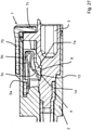
Erkennbar ist, dass die Leiteranschlussklemme 1 ein Betätigungselement 7 hat, wobei das Betätigungselement 7 verschiebbar in dem Isolierstoffgehäuse 2 gelagert ist. Das Betätigungselement 7 hat einen Betätigungsabschnitt 7a, wobei der Betätigungsabschnitt 7a derart mit dem Klemmschenkel 5c in Wechselwirkung steht, dass der Betätigungsabschnitt 7a zum Öffnen der Klemmstelle 6 an dem Klemmschenkel 5c anliegt. Das Betätigungselement 7 ist im Wesentlichen parallel zur Leitereinführungsrichtung L in dem Isolierstoffgehäuse 2 gelagert, wobei das Betätigungselement 7 zur Betätigung in einer Betätigungsrichtung B, parallel zur Leitereinführungsrichtung L, zum Öffnen der Klemmstelle 6 eingerichtet ist.It can be seen that the
Deutlich wird, dass der Betätigungsabschnitt 7a des Betätigungselementes 7 auf einer als längliche Führungsschiene ausgebildete Rastkontur 8 des Isolierstoffgehäuses 2 verschiebbar gelagert ist. Auf der Rastkontur 8 wird der Betätigungsabschnitt 7a während der Verschiebung des Betätigungselementes 7 in der Betätigungsrichtung B geführt. Durch die parallele Ausgestaltung der Leitereinführungsrichtung L und der Betätigungsrichtung B kann vermieden werden, dass der Betätigungsabschnitt 7a in den Bereich der Klemmstelle 6 und/oder in den Bereich, in den der elektrische Leiter eingeführt wird, gelangt und so ein Einstecken des elektrischen Leiters blockiert oder einen eingesteckten elektrischen Leiter beschädigt.It is clear that the
An einem Vorsprung 9 des Isolierstoffgehäuses 2 ist eine Ausnehmung 10 angeordnet, wobei der Betätigungsabschnitt 7a bei geschlossener Klemmstelle in der Ausnehmung 10 aufgenommen werden kann. Dabei ist Kontur des Betätigungsabschnittes 7a an die Kontur der Ausnehmung 10 angepasst.A
Deutlich wird, dass der Betätigungsabschnitt 7a während des Betätigungsvorganges, also während der Verschiebung des Betätigungselementes von einer Ausgangsposition in Betätigungsrichtung B in eine Betätigungsposition, in der die Klemmstelle 6 geöffnet ist, auf der Rastkontur 8 aufliegt und den Klemmschenkel 5c derart verlagert, dass die Klemmstelle 6 geöffnet wird. Der Betätigungsabschnitt 7a ist dabei zwischen dem Klemmschenkel 5c der Klemmfeder 5 und der Rastkontur 8 angeordnet.It is clear that the
Aus
Deutlich wird, dass die Rastkontur 8 einen Höhenversatz 12 hat. Dieser ist aus Betätigungsrichtung B gesehen über der Klemmstelle 6 angeordnet. Wird der Betätigungsabschnitt 7a über diesen Höhenversatz 12 geführt, wird der Betätigungsabschnitt 7a durch die Federkraft des Klemmschenkels 5c weiterhin an die Rastkontur 8 gedrückt, wobei der Betätigungsabschnitt 7a in eine Rastposition gelangt, in der der Betätigungsabschnitt 7a unter Kraftweinwirkung des Klemmschenkels 5c bei geöffneter Klemmstelle 6 an der Rastkontur 8 in einer Klemmposition gehalten wird.It becomes clear that the latching
Deutlich wird, dass das Betätigungselement 7 und die Rastkontur 8 unterschiedlich zur ersten Ausführungsform nach den
Im Unterschied zur ersten Ausführungsform verläuft die Rastkontur 8 bzw. die längliche Führungsschiene aus der Betätigungsrichtung B gesehen aufsteigend, wobei ein Höhenversatz entsteht. Deutlich wird, dass an der Rastkontur 8 eine Rastausnehmung 13 angeordnet ist, wobei an dem Betätigungsabschnitt 7a eine korrespondierende Rastnase 14 angeordnet ist. Wird das Betätigungselement 7 von der Ausgangsstellung in die Betätigungsstellung gemäß der
Weiterhin deutlich wird, dass beide Ausführungsformen nach den
Die
Die
Wird nun, wie die
Die
Soll die Verrastung des Betätigungsabschnitts 7a in der Rastkontur 8 gelöst werden, wird auf das Betätigungselement 7, z.B. auf den Schiebeabschnitt 7b, eine Kraft in einer Entriegelungsrichtung R aufgebracht, wie die
Die
Die
Die
Die
Die
Die
Ein Vergleich der Abbildungen a) und b) zeigt die flexible Auslenkbarkeit des Betätigungsabschnitts 7a über die Gelenkstelle 7d gegenüber den Seitenabschnitten 7e.A comparison of figures a) and b) shows the flexible deflectability of the
Die
Die Leiteranschlussklemme gemäß
Die
Erkennbar ist, dass am freien Ende des Anlageschenkels 5a ein erstes Halteelement 5e und ein zweites Haltelement 5f in eine von dem Klemmschenkel 5c der Klemmfeder 5 wegweisende Richtung aus dem Anlageschenkel 5a herausgestellt sind, z.B. als endseitig hochgebogene Lasche und/oder seitlich eingeschnittene und hochgebogene Lasche. Das erste Halteelement 5e ist an einer ersten Haltekante 4e und das zweite Halteelement 5f an einer zweiten Haltekante 4f gelagert. Dabei sind die Haltekanten 4e, 4f an der Stromschiene 4 angeordnet.It can be seen that at the free end of the
Deutlich wird, dass das erste Halteelement 5e die erste Haltekante 4e umgreift. In Richtung des Federbogens 5b ist das von dem ersten Halteelement 5e beabstandete zweite Halteelement 5f angeordnet, wobei das zweite Haltelement 5f die als Rand einer Halteöffnung 4d ausgebildete zweite Haltekante 4f durchgreift. Das erste Haltelement 5e ist am freien Ende des Anlageschenkels 5a angeordnet, wobei das zweite Halteelement 5f von dem ersten Haltelement 5e beabstandet in Richtung des Federbogens 5b angeordnet ist. Auf diese Weise kann eine stabile Anbindung der Klemmfeder 5 an die Stromschiene 4 und gleichzeitig eine große Beweglichkeit der Klemmfeder 5 gewährleistet werden.It becomes clear that the
Die
Die
Die
Die
Die
Am Schiebeabschnitt 7b kann das Betätigungselement 7 ein erstes Langloch 7g aufweisen, z.B. derart, dass das erste Langloch 7g am freien Ende des Schiebeabschnitts 7b angeordnet ist und zu freien Ende hin offen ist. Durch das erste Langloch 7g kann der Schiebeabschnitt 7b zusätzlich in Längsbewegungsrichtung geführt sein, z.B. durch einen vom Isolierstoffgehäuse 2 abragenden Zapfen, der in das erste Langloch 7g eingreift.The
Das Betätigungselement 7 weist an einem oder beiden Seitenabschnitten 7e jeweils ein zweites Langloch 7h auf. In dem zweiten Langloch 7h kann ein Führungsfortsatz des Isolierstoffgehäuses 2 geführt sein. Auf diese Weise hat das Betätigungselement 7 eine zusätzliche Führung bei seiner Schiebebewegung. Zudem wird verhindert, dass sich das Betätigungselement 7 von dem Isolierstoffgehäuse 2 lösen kann. Das zweite Langloch 7h kann insbesondere mit in Längsrichtung nicht parallelen Seitenwänden ausgebildet sein, z.B. derart, dass die Breite des zweiten Langlochs 7h mit zunehmenden Abstand vom Druckabschnitt 7c geringer wird. Mit anderen Worten, der dem Druckabschnitt 7c zugewandte Bereich des zweiten Langlochs 7h ist breiter als die weiter entfernten Bereiche. Auf diese Weise hat das Betätigungselement 7 ausreichend Bewegungsfreiheit beim Kippvorgang.The
BezugszeichenlisteReference List
- 11
- Leiteranschlussklemmeconductor terminal
- 22
- Isolierstoffgehäuseinsulating housing
- 33
- Leitereinführungsöffnungconductor entry hole
- 44
- Stromschienepower rail
- 4a4a
- Verbindungswandconnecting wall
- 4b4b
- Fixiervorsprungfixing projection
- 4c4c
- Kontaktabschnittcontact section
- 4d4d
- Ausnehmungrecess
- 4e4e
- Erste HaltekanteFirst retaining edge
- 4f4f
- Zweite HaltekanteSecond holding edge
- 55
- Klemmfederclamping spring
- 5a5a
- Anlageschenkelcontact leg
- 5b5b
- Federbogenspring bow
- 5c5c
- Klemmschenkelclamp legs
- 5d5d
- Aussparungrecess
- 5e5e
- Fixierfortsatz Erstes HalteelementFixing extension First holding element
- 5f5f
- Zweites HalteelementSecond holding element
- 5g5g
- konvexer Abschnittconvex section
- 66
- Klemmstelleclamping point
- 77
- Betätigungselementactuator
- 7a7a
- Betätigungsabschnittoperating section
- 7b7b
- Schiebeabschnittsliding section
- 7c7c
- Druckabschnittprint section
- 7d7d
- Gelenkstellearticulation point
- 7e7e
- Seitenabschnittside section
- 7f7f
- konkaver Abschnittconcave section
- 7g7g
- erstes Langlochfirst slot
- 7h7h
- zweites Langlochsecond slot
- 88th
- Rastkonturlocking contour
- 99
- Vorsprunghead Start
- 1010
- Ausnehmungrecess
- 1111
- Rückstellfederreturn spring
- 1212
- Höhenversatzheight offset
- 1313
- Rastausnehmungrecess
- 1414
- Rastnasedetent
- 1515
- Werkzeugtool
- 1616
- Zugentlastungsaufsatzstrain relief attachment
- 1717
- erste Fixierpositionfirst fixation position
- 1818
- zweite Fixierpositionsecond fixation position
- 1919
- Fixierelementfixing element
- 2020
- Kippstelletipping point
- LL
- Leitereinführungsrichtungconductor entry direction
- BB
- Betätigungsrichtungoperating direction
- RR
- Entriegelungsrichtungunlocking direction
ZITATE ENTHALTEN IN DER BESCHREIBUNGQUOTES INCLUDED IN DESCRIPTION
Diese Liste der vom Anmelder aufgeführten Dokumente wurde automatisiert erzeugt und ist ausschließlich zur besseren Information des Lesers aufgenommen. Die Liste ist nicht Bestandteil der deutschen Patent- bzw. Gebrauchsmusteranmeldung. Das DPMA übernimmt keinerlei Haftung für etwaige Fehler oder Auslassungen.This list of documents cited by the applicant was generated automatically and is included solely for the better information of the reader. The list is not part of the German patent or utility model application. The DPMA assumes no liability for any errors or omissions.
Zitierte PatentliteraturPatent Literature Cited
- DE 102017117459 A1 [0002]DE 102017117459 A1 [0002]
Claims (21)
Priority Applications (4)
| Application Number | Priority Date | Filing Date | Title |
|---|---|---|---|
| DE102020119864.7A DE102020119864A1 (en) | 2020-07-28 | 2020-07-28 | conductor terminal |
| CN202180049947.XA CN116057781A (en) | 2020-07-28 | 2021-07-26 | Terminals |
| PCT/EP2021/070866 WO2022023274A2 (en) | 2020-07-28 | 2021-07-26 | Conductor connection terminal |
| EP21755382.5A EP4189782B1 (en) | 2020-07-28 | 2021-07-26 | Conductor connection terminal |
Applications Claiming Priority (1)
| Application Number | Priority Date | Filing Date | Title |
|---|---|---|---|
| DE102020119864.7A DE102020119864A1 (en) | 2020-07-28 | 2020-07-28 | conductor terminal |
Publications (1)
| Publication Number | Publication Date |
|---|---|
| DE102020119864A1 true DE102020119864A1 (en) | 2022-02-03 |
Family
ID=77358211
Family Applications (1)
| Application Number | Title | Priority Date | Filing Date |
|---|---|---|---|
| DE102020119864.7A Pending DE102020119864A1 (en) | 2020-07-28 | 2020-07-28 | conductor terminal |
Country Status (4)
| Country | Link |
|---|---|
| EP (1) | EP4189782B1 (en) |
| CN (1) | CN116057781A (en) |
| DE (1) | DE102020119864A1 (en) |
| WO (1) | WO2022023274A2 (en) |
Cited By (2)
| Publication number | Priority date | Publication date | Assignee | Title |
|---|---|---|---|---|
| LU502538B1 (en) * | 2022-07-21 | 2024-01-22 | Phoenix Contact Gmbh & Co | Terminal for connecting an electrical cable |
| DE202024105035U1 (en) * | 2024-09-04 | 2025-12-18 | WAGO Verwaltungsgesellschaft mit beschränkter Haftung | conductor connection terminal |
Citations (8)
| Publication number | Priority date | Publication date | Assignee | Title |
|---|---|---|---|---|
| JPH04155783A (en) | 1990-10-18 | 1992-05-28 | Matsushita Electric Works Ltd | Wire connection terminal |
| DE10255190A1 (en) | 2002-11-27 | 2004-06-17 | Phoenix Contact Gmbh & Co. Kg | Round plug connector unit has clamp arrangement fixed to its plug pin and/or socket, and unlocking device in insulating body that moves clamp leg against spring force to form gap for feeding conductor |
| DE102008039232A1 (en) | 2008-08-22 | 2010-02-25 | Phoenix Contact Gmbh & Co. Kg | Electrical connecting terminal for use as e.g. print terminal, for connection of flexible lead to printed circuit board, has projection and passage locked with one another in operating latch such that operating latch is held in position |
| DE202010016895U1 (en) | 2010-12-21 | 2012-03-22 | Weidmüller Interface GmbH & Co. KG | Connection device with spring clip |
| DE102016116966A1 (en) | 2016-09-09 | 2018-03-15 | Wago Verwaltungsgesellschaft Mbh | Spring terminal connection and conductor terminal |
| DE102017117459A1 (en) | 2017-08-02 | 2019-02-07 | Phoenix Contact Gmbh & Co. Kg | Connecting device for connecting an electrical line |
| DE102018122806A1 (en) | 2017-10-30 | 2019-05-02 | WAGO Verwaltungsgesellschaft mit beschränkter Haftung | Conductor terminal and contact insert |
| DE102019125212A1 (en) | 2018-12-04 | 2020-06-04 | WAGO Verwaltungsgesellschaft mit beschränkter Haftung | Spring terminal |
Family Cites Families (4)
| Publication number | Priority date | Publication date | Assignee | Title |
|---|---|---|---|---|
| JPH05144485A (en) * | 1991-11-26 | 1993-06-11 | Matsushita Electric Works Ltd | Quick coupling terminal device of wiring apparatus |
| DE102008062137B4 (en) * | 2008-12-16 | 2011-06-09 | Wago Verwaltungsgesellschaft Mbh | Conductor terminal |
| DE102015101893B4 (en) * | 2015-02-10 | 2022-01-20 | Phoenix Contact Gmbh & Co. Kg | conductor terminal |
| DE202018106900U1 (en) * | 2018-12-04 | 2020-03-06 | WAGO Verwaltungsgesellschaft mit beschränkter Haftung | Spring terminal |
-
2020
- 2020-07-28 DE DE102020119864.7A patent/DE102020119864A1/en active Pending
-
2021
- 2021-07-26 CN CN202180049947.XA patent/CN116057781A/en active Pending
- 2021-07-26 EP EP21755382.5A patent/EP4189782B1/en active Active
- 2021-07-26 WO PCT/EP2021/070866 patent/WO2022023274A2/en not_active Ceased
Patent Citations (8)
| Publication number | Priority date | Publication date | Assignee | Title |
|---|---|---|---|---|
| JPH04155783A (en) | 1990-10-18 | 1992-05-28 | Matsushita Electric Works Ltd | Wire connection terminal |
| DE10255190A1 (en) | 2002-11-27 | 2004-06-17 | Phoenix Contact Gmbh & Co. Kg | Round plug connector unit has clamp arrangement fixed to its plug pin and/or socket, and unlocking device in insulating body that moves clamp leg against spring force to form gap for feeding conductor |
| DE102008039232A1 (en) | 2008-08-22 | 2010-02-25 | Phoenix Contact Gmbh & Co. Kg | Electrical connecting terminal for use as e.g. print terminal, for connection of flexible lead to printed circuit board, has projection and passage locked with one another in operating latch such that operating latch is held in position |
| DE202010016895U1 (en) | 2010-12-21 | 2012-03-22 | Weidmüller Interface GmbH & Co. KG | Connection device with spring clip |
| DE102016116966A1 (en) | 2016-09-09 | 2018-03-15 | Wago Verwaltungsgesellschaft Mbh | Spring terminal connection and conductor terminal |
| DE102017117459A1 (en) | 2017-08-02 | 2019-02-07 | Phoenix Contact Gmbh & Co. Kg | Connecting device for connecting an electrical line |
| DE102018122806A1 (en) | 2017-10-30 | 2019-05-02 | WAGO Verwaltungsgesellschaft mit beschränkter Haftung | Conductor terminal and contact insert |
| DE102019125212A1 (en) | 2018-12-04 | 2020-06-04 | WAGO Verwaltungsgesellschaft mit beschränkter Haftung | Spring terminal |
Cited By (3)
| Publication number | Priority date | Publication date | Assignee | Title |
|---|---|---|---|---|
| LU502538B1 (en) * | 2022-07-21 | 2024-01-22 | Phoenix Contact Gmbh & Co | Terminal for connecting an electrical cable |
| WO2024017993A1 (en) * | 2022-07-21 | 2024-01-25 | Phoenix Contact Gmbh & Co. Kg | Connection terminal for connecting an electrical line |
| DE202024105035U1 (en) * | 2024-09-04 | 2025-12-18 | WAGO Verwaltungsgesellschaft mit beschränkter Haftung | conductor connection terminal |
Also Published As
| Publication number | Publication date |
|---|---|
| WO2022023274A3 (en) | 2022-04-07 |
| CN116057781A (en) | 2023-05-02 |
| EP4189782A2 (en) | 2023-06-07 |
| CN116057781A8 (en) | 2023-08-01 |
| WO2022023274A2 (en) | 2022-02-03 |
| EP4189782B1 (en) | 2025-11-19 |
Similar Documents
| Publication | Publication Date | Title |
|---|---|---|
| DE102014114026B4 (en) | Conductor terminal and method of assembly | |
| DE102022100132A1 (en) | Electrical connection device | |
| DE102018102011B4 (en) | Electrical connector | |
| DE202017105467U1 (en) | Conductor terminal | |
| DE102019111453A1 (en) | Spring clamp terminal for conductors | |
| DE102016108826A1 (en) | terminal | |
| EP4189782B1 (en) | Conductor connection terminal | |
| DE102021111502A1 (en) | conductor terminal | |
| DE102017124670A1 (en) | Electrical plug connection | |
| DE202020100782U1 (en) | Conductor connection terminal | |
| DE102020126486A1 (en) | Holding frame for a connector | |
| DE2559861B1 (en) | Lockable push button switch | |
| DE69901287T2 (en) | ELECTRICAL PLUG WITH AN ACTUATOR | |
| EP3945639B1 (en) | Conductor connecting terminal | |
| EP1174892A2 (en) | Mechanical locking device for on- and off-position of an electrical push switch | |
| DE2640597A1 (en) | SWITCHING DEVICE | |
| DE202024102627U1 (en) | conductor connection terminal | |
| DE102018109545A1 (en) | Spring terminal connection and conductor terminal | |
| DE102025114868A1 (en) | Spring-cage terminal and conductor connection terminal | |
| DE202024102624U1 (en) | conductor connection terminal | |
| DE102016105428A1 (en) | terminal | |
| DE202024102553U1 (en) | conductor connection terminal | |
| DE102025132734A1 (en) | Spring clamp connection and conductor connection terminal | |
| DE202024104668U1 (en) | conductor connection terminal | |
| DE102025114869A1 (en) | Spring-cage terminal and conductor connection terminal |
Legal Events
| Date | Code | Title | Description |
|---|---|---|---|
| R012 | Request for examination validly filed | ||
| R016 | Response to examination communication | ||
| R082 | Change of representative |
Representative=s name: MEISSNER BOLTE PATENTANWAELTE RECHTSANWAELTE P, DE |