DE102020117123A1 - MATERIAL FOR HOLE TRANSPORT LAYER, MATERIAL FOR HOLE INJECTION LAYER, ORGANIC COMPOUND, LIGHT EMITTING DEVICE, LIGHT EMITTING DEVICE, ELECTRONIC DEVICE AND LIGHTING DEVICE - Google Patents
MATERIAL FOR HOLE TRANSPORT LAYER, MATERIAL FOR HOLE INJECTION LAYER, ORGANIC COMPOUND, LIGHT EMITTING DEVICE, LIGHT EMITTING DEVICE, ELECTRONIC DEVICE AND LIGHTING DEVICE Download PDFInfo
- Publication number
- DE102020117123A1 DE102020117123A1 DE102020117123.4A DE102020117123A DE102020117123A1 DE 102020117123 A1 DE102020117123 A1 DE 102020117123A1 DE 102020117123 A DE102020117123 A DE 102020117123A DE 102020117123 A1 DE102020117123 A1 DE 102020117123A1
- Authority
- DE
- Germany
- Prior art keywords
- aromatic group
- group
- carbon atoms
- emitting device
- light
- Prior art date
- Legal status (The legal status is an assumption and is not a legal conclusion. Google has not performed a legal analysis and makes no representation as to the accuracy of the status listed.)
- Pending
Links
- 0 C*(C)*CCC(C)(*(C)c1c(*)c(*)c(*)c(C)c1*)c1ccccc1 Chemical compound C*(C)*CCC(C)(*(C)c1c(*)c(*)c(*)c(C)c1*)c1ccccc1 0.000 description 8
- QRMLAMCEPKEKHS-UHFFFAOYSA-N CC1(C)c(cc(cc2)Nc(cc3)ccc3-c3ccccc3)c2-c2ccccc12 Chemical compound CC1(C)c(cc(cc2)Nc(cc3)ccc3-c3ccccc3)c2-c2ccccc12 QRMLAMCEPKEKHS-UHFFFAOYSA-N 0.000 description 1
- OBARUOOPPWHZRQ-UHFFFAOYSA-N CC1(C)c(cc(cc2)Nc(cccc3)c3-c3ccccc3)c2-c2c1cccc2 Chemical compound CC1(C)c(cc(cc2)Nc(cccc3)c3-c3ccccc3)c2-c2c1cccc2 OBARUOOPPWHZRQ-UHFFFAOYSA-N 0.000 description 1
- OQZAQBGJENJMHT-UHFFFAOYSA-N COc1cc(Br)cc(Br)c1 Chemical compound COc1cc(Br)cc(Br)c1 OQZAQBGJENJMHT-UHFFFAOYSA-N 0.000 description 1
- JLNMBIKJQAKQBH-UHFFFAOYSA-N Nc1ccc(C2CCCCC2)cc1 Chemical compound Nc1ccc(C2CCCCC2)cc1 JLNMBIKJQAKQBH-UHFFFAOYSA-N 0.000 description 1
Images






Classifications
-
- C—CHEMISTRY; METALLURGY
- C09—DYES; PAINTS; POLISHES; NATURAL RESINS; ADHESIVES; COMPOSITIONS NOT OTHERWISE PROVIDED FOR; APPLICATIONS OF MATERIALS NOT OTHERWISE PROVIDED FOR
- C09K—MATERIALS FOR MISCELLANEOUS APPLICATIONS, NOT PROVIDED FOR ELSEWHERE
- C09K11/00—Luminescent materials, e.g. electroluminescent or chemiluminescent
- C09K11/06—Luminescent materials, e.g. electroluminescent or chemiluminescent containing organic luminescent materials
-
- C—CHEMISTRY; METALLURGY
- C07—ORGANIC CHEMISTRY
- C07C—ACYCLIC OR CARBOCYCLIC COMPOUNDS
- C07C211/00—Compounds containing amino groups bound to a carbon skeleton
- C07C211/43—Compounds containing amino groups bound to a carbon skeleton having amino groups bound to carbon atoms of six-membered aromatic rings of the carbon skeleton
- C07C211/54—Compounds containing amino groups bound to a carbon skeleton having amino groups bound to carbon atoms of six-membered aromatic rings of the carbon skeleton having amino groups bound to two or three six-membered aromatic rings
-
- C—CHEMISTRY; METALLURGY
- C07—ORGANIC CHEMISTRY
- C07C—ACYCLIC OR CARBOCYCLIC COMPOUNDS
- C07C211/00—Compounds containing amino groups bound to a carbon skeleton
- C07C211/43—Compounds containing amino groups bound to a carbon skeleton having amino groups bound to carbon atoms of six-membered aromatic rings of the carbon skeleton
- C07C211/57—Compounds containing amino groups bound to a carbon skeleton having amino groups bound to carbon atoms of six-membered aromatic rings of the carbon skeleton having amino groups bound to carbon atoms of six-membered aromatic rings being part of condensed ring systems of the carbon skeleton
-
- C—CHEMISTRY; METALLURGY
- C07—ORGANIC CHEMISTRY
- C07C—ACYCLIC OR CARBOCYCLIC COMPOUNDS
- C07C211/00—Compounds containing amino groups bound to a carbon skeleton
- C07C211/43—Compounds containing amino groups bound to a carbon skeleton having amino groups bound to carbon atoms of six-membered aromatic rings of the carbon skeleton
- C07C211/57—Compounds containing amino groups bound to a carbon skeleton having amino groups bound to carbon atoms of six-membered aromatic rings of the carbon skeleton having amino groups bound to carbon atoms of six-membered aromatic rings being part of condensed ring systems of the carbon skeleton
- C07C211/61—Compounds containing amino groups bound to a carbon skeleton having amino groups bound to carbon atoms of six-membered aromatic rings of the carbon skeleton having amino groups bound to carbon atoms of six-membered aromatic rings being part of condensed ring systems of the carbon skeleton with at least one of the condensed ring systems formed by three or more rings
-
- H—ELECTRICITY
- H10—SEMICONDUCTOR DEVICES; ELECTRIC SOLID-STATE DEVICES NOT OTHERWISE PROVIDED FOR
- H10K—ORGANIC ELECTRIC SOLID-STATE DEVICES
- H10K50/00—Organic light-emitting devices
- H10K50/10—OLEDs or polymer light-emitting diodes [PLED]
- H10K50/14—Carrier transporting layers
- H10K50/15—Hole transporting layers
-
- H—ELECTRICITY
- H10—SEMICONDUCTOR DEVICES; ELECTRIC SOLID-STATE DEVICES NOT OTHERWISE PROVIDED FOR
- H10K—ORGANIC ELECTRIC SOLID-STATE DEVICES
- H10K50/00—Organic light-emitting devices
- H10K50/10—OLEDs or polymer light-emitting diodes [PLED]
- H10K50/17—Carrier injection layers
-
- H—ELECTRICITY
- H10—SEMICONDUCTOR DEVICES; ELECTRIC SOLID-STATE DEVICES NOT OTHERWISE PROVIDED FOR
- H10K—ORGANIC ELECTRIC SOLID-STATE DEVICES
- H10K59/00—Integrated devices, or assemblies of multiple devices, comprising at least one organic light-emitting element covered by group H10K50/00
-
- H—ELECTRICITY
- H10—SEMICONDUCTOR DEVICES; ELECTRIC SOLID-STATE DEVICES NOT OTHERWISE PROVIDED FOR
- H10K—ORGANIC ELECTRIC SOLID-STATE DEVICES
- H10K85/00—Organic materials used in the body or electrodes of devices covered by this subclass
- H10K85/60—Organic compounds having low molecular weight
- H10K85/615—Polycyclic condensed aromatic hydrocarbons, e.g. anthracene
-
- H—ELECTRICITY
- H10—SEMICONDUCTOR DEVICES; ELECTRIC SOLID-STATE DEVICES NOT OTHERWISE PROVIDED FOR
- H10K—ORGANIC ELECTRIC SOLID-STATE DEVICES
- H10K85/00—Organic materials used in the body or electrodes of devices covered by this subclass
- H10K85/60—Organic compounds having low molecular weight
- H10K85/615—Polycyclic condensed aromatic hydrocarbons, e.g. anthracene
- H10K85/622—Polycyclic condensed aromatic hydrocarbons, e.g. anthracene containing four rings, e.g. pyrene
-
- H—ELECTRICITY
- H10—SEMICONDUCTOR DEVICES; ELECTRIC SOLID-STATE DEVICES NOT OTHERWISE PROVIDED FOR
- H10K—ORGANIC ELECTRIC SOLID-STATE DEVICES
- H10K85/00—Organic materials used in the body or electrodes of devices covered by this subclass
- H10K85/60—Organic compounds having low molecular weight
- H10K85/615—Polycyclic condensed aromatic hydrocarbons, e.g. anthracene
- H10K85/626—Polycyclic condensed aromatic hydrocarbons, e.g. anthracene containing more than one polycyclic condensed aromatic rings, e.g. bis-anthracene
-
- H—ELECTRICITY
- H10—SEMICONDUCTOR DEVICES; ELECTRIC SOLID-STATE DEVICES NOT OTHERWISE PROVIDED FOR
- H10K—ORGANIC ELECTRIC SOLID-STATE DEVICES
- H10K85/00—Organic materials used in the body or electrodes of devices covered by this subclass
- H10K85/60—Organic compounds having low molecular weight
- H10K85/631—Amine compounds having at least two aryl rest on at least one amine-nitrogen atom, e.g. triphenylamine
-
- H—ELECTRICITY
- H10—SEMICONDUCTOR DEVICES; ELECTRIC SOLID-STATE DEVICES NOT OTHERWISE PROVIDED FOR
- H10K—ORGANIC ELECTRIC SOLID-STATE DEVICES
- H10K85/00—Organic materials used in the body or electrodes of devices covered by this subclass
- H10K85/60—Organic compounds having low molecular weight
- H10K85/631—Amine compounds having at least two aryl rest on at least one amine-nitrogen atom, e.g. triphenylamine
- H10K85/633—Amine compounds having at least two aryl rest on at least one amine-nitrogen atom, e.g. triphenylamine comprising polycyclic condensed aromatic hydrocarbons as substituents on the nitrogen atom
-
- C—CHEMISTRY; METALLURGY
- C07—ORGANIC CHEMISTRY
- C07C—ACYCLIC OR CARBOCYCLIC COMPOUNDS
- C07C2601/00—Systems containing only non-condensed rings
- C07C2601/12—Systems containing only non-condensed rings with a six-membered ring
- C07C2601/14—The ring being saturated
-
- C—CHEMISTRY; METALLURGY
- C07—ORGANIC CHEMISTRY
- C07C—ACYCLIC OR CARBOCYCLIC COMPOUNDS
- C07C2601/00—Systems containing only non-condensed rings
- C07C2601/18—Systems containing only non-condensed rings with a ring being at least seven-membered
- C07C2601/20—Systems containing only non-condensed rings with a ring being at least seven-membered the ring being twelve-membered
-
- C—CHEMISTRY; METALLURGY
- C07—ORGANIC CHEMISTRY
- C07C—ACYCLIC OR CARBOCYCLIC COMPOUNDS
- C07C2603/00—Systems containing at least three condensed rings
- C07C2603/02—Ortho- or ortho- and peri-condensed systems
- C07C2603/04—Ortho- or ortho- and peri-condensed systems containing three rings
- C07C2603/06—Ortho- or ortho- and peri-condensed systems containing three rings containing at least one ring with less than six ring members
- C07C2603/10—Ortho- or ortho- and peri-condensed systems containing three rings containing at least one ring with less than six ring members containing five-membered rings
- C07C2603/12—Ortho- or ortho- and peri-condensed systems containing three rings containing at least one ring with less than six ring members containing five-membered rings only one five-membered ring
- C07C2603/18—Fluorenes; Hydrogenated fluorenes
-
- C—CHEMISTRY; METALLURGY
- C07—ORGANIC CHEMISTRY
- C07C—ACYCLIC OR CARBOCYCLIC COMPOUNDS
- C07C2603/00—Systems containing at least three condensed rings
- C07C2603/93—Spiro compounds
- C07C2603/95—Spiro compounds containing "not free" spiro atoms
- C07C2603/96—Spiro compounds containing "not free" spiro atoms containing at least one ring with less than six members
- C07C2603/97—Spiro compounds containing "not free" spiro atoms containing at least one ring with less than six members containing five-membered rings
-
- C—CHEMISTRY; METALLURGY
- C09—DYES; PAINTS; POLISHES; NATURAL RESINS; ADHESIVES; COMPOSITIONS NOT OTHERWISE PROVIDED FOR; APPLICATIONS OF MATERIALS NOT OTHERWISE PROVIDED FOR
- C09K—MATERIALS FOR MISCELLANEOUS APPLICATIONS, NOT PROVIDED FOR ELSEWHERE
- C09K2211/00—Chemical nature of organic luminescent or tenebrescent compounds
- C09K2211/10—Non-macromolecular compounds
- C09K2211/1003—Carbocyclic compounds
- C09K2211/1007—Non-condensed systems
-
- C—CHEMISTRY; METALLURGY
- C09—DYES; PAINTS; POLISHES; NATURAL RESINS; ADHESIVES; COMPOSITIONS NOT OTHERWISE PROVIDED FOR; APPLICATIONS OF MATERIALS NOT OTHERWISE PROVIDED FOR
- C09K—MATERIALS FOR MISCELLANEOUS APPLICATIONS, NOT PROVIDED FOR ELSEWHERE
- C09K2211/00—Chemical nature of organic luminescent or tenebrescent compounds
- C09K2211/10—Non-macromolecular compounds
- C09K2211/1003—Carbocyclic compounds
- C09K2211/1011—Condensed systems
-
- C—CHEMISTRY; METALLURGY
- C09—DYES; PAINTS; POLISHES; NATURAL RESINS; ADHESIVES; COMPOSITIONS NOT OTHERWISE PROVIDED FOR; APPLICATIONS OF MATERIALS NOT OTHERWISE PROVIDED FOR
- C09K—MATERIALS FOR MISCELLANEOUS APPLICATIONS, NOT PROVIDED FOR ELSEWHERE
- C09K2211/00—Chemical nature of organic luminescent or tenebrescent compounds
- C09K2211/10—Non-macromolecular compounds
- C09K2211/1003—Carbocyclic compounds
- C09K2211/1014—Carbocyclic compounds bridged by heteroatoms, e.g. N, P, Si or B
-
- H—ELECTRICITY
- H10—SEMICONDUCTOR DEVICES; ELECTRIC SOLID-STATE DEVICES NOT OTHERWISE PROVIDED FOR
- H10K—ORGANIC ELECTRIC SOLID-STATE DEVICES
- H10K2101/00—Properties of the organic materials covered by group H10K85/00
- H10K2101/20—Delayed fluorescence emission
-
- H—ELECTRICITY
- H10—SEMICONDUCTOR DEVICES; ELECTRIC SOLID-STATE DEVICES NOT OTHERWISE PROVIDED FOR
- H10K—ORGANIC ELECTRIC SOLID-STATE DEVICES
- H10K2101/00—Properties of the organic materials covered by group H10K85/00
- H10K2101/20—Delayed fluorescence emission
- H10K2101/25—Delayed fluorescence emission using exciplex
Landscapes
- Chemical & Material Sciences (AREA)
- Organic Chemistry (AREA)
- Engineering & Computer Science (AREA)
- Materials Engineering (AREA)
- Physics & Mathematics (AREA)
- Spectroscopy & Molecular Physics (AREA)
- Optics & Photonics (AREA)
- Electroluminescent Light Sources (AREA)
- Organic Low-Molecular-Weight Compounds And Preparation Thereof (AREA)
- Low-Molecular Organic Synthesis Reactions Using Catalysts (AREA)
Abstract
Ein Material für eine Lochtransportschicht umfasst eine Monoamin-Verbindung. Die erste aromatische Gruppe, die zweite aromatische Gruppe und die dritte aromatische Gruppe sind an das Stickstoffatom der Monoamin-Verbindung gebunden. Die erste und zweite aromatische Gruppe umfassen jeweils unabhängig voneinander 1 bis 3 Benzolringe. Die erste aromatische Gruppe und/oder die zweite aromatische Gruppe umfassen/umfasst eine oder mehrere Kohlenwasserstoff-Gruppen, die jeweils 1 bis 12 Kohlenstoffatome aufweisen, die jeweils nur durch die sp3-Hybridorbitale eine Bindung bilden. Die Gesamtzahl der Kohlenstoffatome in der Kohlenwasserstoff-Gruppe in der ersten oder zweiten aromatischen Gruppe ist 6 oder mehr. Die Gesamtzahl der Kohlenstoffatome in den gesamten Kohlenwasserstoff-Gruppen in der ersten und zweiten aromatischen Gruppe ist 8 oder mehr. Die dritte aromatische Gruppe ist ein substituierter oder unsubstituierter monocyclischer kondensierter Ring oder ein substituierter oder unsubstituierter bicyclischer oder tricyclischer kondensierter Ring.A material for a hole transport layer includes a monoamine compound. The first aromatic group, the second aromatic group and the third aromatic group are bonded to the nitrogen atom of the monoamine compound. The first and second aromatic groups each independently comprise 1 to 3 benzene rings. The first aromatic group and / or the second aromatic group comprise / comprises one or more hydrocarbon groups each having 1 to 12 carbon atoms, each of which only forms a bond through the sp3 hybrid orbitals. The total number of carbon atoms in the hydrocarbon group in the first or second aromatic group is 6 or more. The total number of carbon atoms in the total hydrocarbon groups in the first and second aromatic groups is 8 or more. The third aromatic group is a substituted or unsubstituted monocyclic condensed ring or a substituted or unsubstituted bicyclic or tricyclic condensed ring.
Description
Hintergrund der ErfindungBackground of the invention
Gebiet der ErfindungField of invention
Ausführungsformen der vorliegenden Erfindung betreffen eine organische Verbindung, ein Licht emittierendes Element, eine Licht emittierende Vorrichtung, ein Anzeigemodul, ein Beleuchtungsmodul, eine Anzeigevorrichtung, eine Licht emittierende Einrichtung, ein elektronisches Gerät und eine Beleuchtungsvorrichtung. Es sei angemerkt, dass eine Ausführungsform der vorliegenden Erfindung nicht auf das vorstehende technische Gebiet beschränkt ist. Das technische Gebiet einer Ausführungsform der in dieser Beschreibung und dergleichen offenbarten Erfindung betrifft einen Gegenstand, ein Verfahren oder ein Herstellungsverfahren. Eine Ausführungsform der vorliegenden Erfindung betrifft einen Prozess, eine Maschine, ein Erzeugnis oder eine Zusammensetzung. Spezifische Beispiele für das technische Gebiet einer Ausführungsform der in dieser Beschreibung offenbarten vorliegenden Erfindung umfassen eine Halbleitervorrichtung, eine Anzeigevorrichtung, eine Flüssigkristallanzeigevorrichtung, eine Licht emittierende Einrichtung, eine Beleuchtungsvorrichtung, eine Energiespeichervorrichtung, eine Speichervorrichtung, eine Abbildungsvorrichtung, ein Betriebsverfahren dafür und ein Herstellungsverfahren dafür.Embodiments of the present invention relate to an organic compound, a light-emitting element, a light-emitting device, a display module, a lighting module, a display device, a light-emitting device, an electronic device, and a lighting device. It should be noted that an embodiment of the present invention is not limited to the above technical field. The technical field of an embodiment of the invention disclosed in this specification and the like relates to an article, a method, or a manufacturing method. One embodiment of the present invention relates to a process, a machine, an article or a composition. Specific examples of the technical field of an embodiment of the present invention disclosed in this specification include a semiconductor device, a display device, a liquid crystal display device, a light emitting device, a lighting device, an energy storage device, a storage device, an imaging device, an operating method therefor, and a manufacturing method therefor.
Beschreibung des Standes der TechnikDescription of the prior art
Licht emittierende Vorrichtungen (organische EL-Vorrichtungen), die organische Verbindungen umfassen und Elektrolumineszenz (EL) nutzen, kamen in der Praxis vermehrt zum Einsatz. Bei der grundlegenden Struktur von derartiger Licht emittierender Vorrichtungen ist eine organische Verbindungsschicht, die ein Licht emittierendes Material enthält (eine EL-Schicht), zwischen einem Paar von Elektroden angeordnet. Ladungsträger werden durch Anlegen einer Spannung an das Element injiziert, und die Rekombinationsenergie der Ladungsträger wird genutzt, wodurch eine Lichtemission von dem Licht emittierenden Material erhalten werden kann.Light-emitting devices (organic EL devices) comprising organic compounds and using electroluminescence (EL) have been increasingly used in practice. In the basic structure of such light emitting devices, an organic compound layer containing a light emitting material (an EL layer) is disposed between a pair of electrodes. Carriers are injected by applying a voltage to the element, and the recombination energy of the carriers is used, whereby light emission can be obtained from the light-emitting material.
Derartige Licht emittierende Vorrichtungen sind selbstleuchtend und daher weisen sie, wenn sie als Pixel einer Anzeige verwendet werden, gegenüber Flüssigkristallanzeigen beispielsweise die folgenden Vorteile, wie z. B. eine hohe Sichtbarkeit und keinen Bedarf an einer Hintergrundbeleuchtung, auf und sie sind als Flachbildschirmanzeigevorrichtungen geeignet. Anzeigen, die derartige Licht emittierende Vorrichtungen umfassen, sind auch insofern sehr vorteilhaft, als sie dünn und leichtgewichtig sein können. Außerdem weisen derartige Licht emittierende Vorrichtungen auch ein Merkmal auf, dass die Ansprechzeit sehr schnell ist.Such light-emitting devices are self-luminous and therefore, when they are used as a pixel of a display, they have the following advantages over liquid crystal displays, e.g. B. have high visibility and no need for a backlight, and they are suitable as flat panel display devices. Displays incorporating such light emitting devices are also very advantageous in that they can be thin and lightweight. In addition, such light emitting devices also have a feature that the response time is very fast.
Da Licht emittierende Schichten derartiger Licht emittierender Vorrichtungen sukzessiv zweidimensional ausgebildet werden können, kann eine planare Lichtemission erhalten werden. Es ist schwierig, dieses Merkmal mit Punktlichtquellen, die durch Glühlampen und LEDs typisiert werden, oder linearen Lichtquellen, die durch Fluoreszenzlampen typisiert werden, zu realisieren; daher haben die Licht emittierenden Vorrichtungen ebenfalls ein großes Potential als planare Lichtquellen, die an Beleuchtungsvorrichtungen und dergleichen angelegt werden können.Since light emitting layers of such light emitting devices can be successively formed two-dimensionally, planar light emission can be obtained. It is difficult to realize this feature with point light sources typed by incandescent lamps and LEDs or linear light sources typed by fluorescent lamps; therefore, the light-emitting devices also have great potential as planar light sources that can be applied to lighting devices and the like.
Anzeigen oder Beleuchtungsvorrichtungen, die Licht emittierende Vorrichtungen umfassen, sind, wie vorstehend beschrieben, für eine Vielzahl von elektronischen Geräten geeignet, und die Forschung und Entwicklung von Licht emittierenden Vorrichtungen ist für vorteilhaftere Eigenschaften vorangeschritten.Displays or lighting devices comprising light emitting devices are suitable for a variety of electronic devices as described above, and research and development of light emitting devices has advanced for more advantageous properties.
Bei einer organischen EL-Vorrichtung ist eine niedrige Auskopplungseffizienz ein häufiges Problem. Insbesondere ist die Abschwächung infolge einer Reflexion, die durch eine Differenz des Brechungsindex zwischen benachbarten Schichten verursacht wird, eine Hauptursache einer Verringerung der Effizienz der Vorrichtung. Um diesen Einfluss zu verringern, ist eine Struktur vorgeschlagen worden, bei der eine Schicht aus einem Material mit niedrigem Brechungsindex in einer EL-Schicht enthalten ist (siehe z. B. Nicht-Patentdokument 1).In an organic EL device, a low extraction efficiency is a common problem. In particular, the attenuation due to reflection caused by a difference in refractive index between adjacent layers is a major cause of lowering the efficiency of the device. In order to reduce this influence, a structure has been proposed in which a layer made of a low refractive index material is included in an EL layer (see, for example, Non-Patent Document 1).
Eine Licht emittierende Vorrichtung mit dieser Struktur kann eine höhere Auskopplungseffizienz und eine höhere externe Quanteneffizienz aufweisen als eine Licht emittierende Vorrichtung mit einer herkömmlichen Struktur; jedoch ist es nicht einfach, dass eine derartige Schicht mit niedrigem Brechungsindex in einer EL-Schicht ausgebildet wird, ohne andere wesentliche Eigenschaften der Licht emittierenden Vorrichtung nachteilig zu beeinflussen. Dies liegt daran, dass ein niedriger Brechungsindex in einer Trade-off-Beziehung bzw. Austauschbeziehung zu einer hohen Ladungsträgertransporteigenschaft oder einer hohen Zuverlässigkeit einer Licht emittierenden Vorrichtung steht, die eine Schicht mit niedrigem Brechungsindex umfasst. Dieses Problem wird dadurch verursacht, dass die Ladungsträgertransporteigenschaft und die Zuverlässigkeit einer organischen Verbindung stark von einer ungesättigten Bindung abhängen und eine organische Verbindung mit vielen ungesättigten Bindungen die Tendenz eines hohen Brechungsindex aufweist.A light-emitting device having this structure can have a higher coupling-out efficiency and a higher external quantum efficiency than a light-emitting device having a conventional structure; however, it is not easy for such a low refractive index layer to be formed in an EL layer without adversely affecting other essential properties of the light-emitting device. This is because a low refractive index is in a trade-off relationship or exchange relationship with a high charge carrier transport property or a high one Reliability of a light emitting device that includes a low refractive index layer. This problem is caused in that the carrier transport property and the reliability of an organic compound are strongly dependent on an unsaturated bond, and an organic compound having many unsaturated bonds tends to have a high refractive index.
[Referenz][Reference]
-
[Patentdokument 1]
Japanische Patentoffenlegungsschrift Nr. H11-282181 Japanese Patent Laid-Open No. H11-282181 -
[Patentdokument 2]
Japanische Patentoffenlegungsschrift Nr. 2009-91304 Japanese Patent Laid-Open No. 2009-91304 -
[Patentdokument 3]
US-Patentanmeldung mit der Veröffentlichungsnummer 2010/104969 U.S. Patent Application Publication Number 2010/104969 -
[Nicht-Patentdokument 1]
Jaeho Lee et al., „Synergetic electrode architecture for efficient graphene-based flexible organic light-emitting diodes“, nature COMMUNICATIONS, am 2. Juni, 2016, DOI: 10.1038/ncomms 11791. Jaeho Lee et al., “Synergetic electrode architecture for efficient graphene-based flexible organic light-emitting diodes”, nature COMMUNICATIONS, on June 2, 2016, DOI: 10.1038 / ncomms 11791.
Zusammenfassung der ErfindungSummary of the invention
Eine Aufgabe einer Ausführungsform der vorliegenden Erfindung ist, ein neuartiges Material für eine Lochtransportschicht bereitzustellen. Eine weitere Aufgabe einer Ausführungsform der vorliegenden Erfindung ist, ein Material für eine Lochtransportschicht mit niedrigem Brechungsindex bereitzustellen. Eine weitere Aufgabe einer Ausführungsform der vorliegenden Erfindung ist, ein Material für eine Lochtransportschicht mit niedrigem Brechungsindex und einer Ladungsträgertransporteigenschaft bereitzustellen. Eine weitere Aufgabe einer Ausführungsform der vorliegenden Erfindung ist, ein Material für eine Lochtransportschicht mit niedrigem Brechungsindex und einer Lochtransporteigenschaft bereitzustellen.An object of one embodiment of the present invention is to provide a novel material for a hole transport layer. Another object of an embodiment of the present invention is to provide a material for a hole transport layer having a low refractive index. Another object of an embodiment of the present invention is to provide a material for a hole transport layer having a low refractive index and a carrier transport property. Another object of an embodiment of the present invention is to provide a material for a hole transport layer having a low refractive index and a hole transport property.
Eine Aufgabe einer Ausführungsform der vorliegenden Erfindung ist, ein neuartiges Material für eine Lochinjektionsschicht bereitzustellen. Eine weitere Aufgabe einer Ausführungsform der vorliegenden Erfindung ist, ein Material für eine Lochinjektionsschicht mit niedrigem Brechungsindex bereitzustellen. Eine weitere Aufgabe einer Ausführungsform der vorliegenden Erfindung ist, ein Material für eine Lochinjektionsschicht mit niedrigem Brechungsindex und einer Ladungsträgertransporteigenschaft bereitzustellen. Eine weitere Aufgabe einer Ausführungsform der vorliegenden Erfindung ist, ein Material für eine Lochinjektionsschicht mit niedrigem Brechungsindex und einer Lochtransporteigenschaft bereitzustellen.An object of one embodiment of the present invention is to provide a novel material for a hole injection layer. Another object of an embodiment of the present invention is to provide a material for a hole injection layer having a low refractive index. Another object of an embodiment of the present invention is to provide a material for a hole injection layer having a low refractive index and a carrier transport property. Another object of an embodiment of the present invention is to provide a material for a hole injection layer having a low refractive index and a hole transport property.
Eine Aufgabe einer Ausführungsform der vorliegenden Erfindung ist, eine neuartige organische Verbindung bereitzustellen. Eine weitere Aufgabe einer Ausführungsform der vorliegenden Erfindung ist, eine neuartige organische Verbindung mit einer Ladungsträgertransporteigenschaft bereitzustellen. Eine weitere Aufgabe einer Ausführungsform der vorliegenden Erfindung ist, eine neuartige organische Verbindung mit einer Lochtransporteigenschaft bereitzustellen. Eine Aufgabe einer Ausführungsform der vorliegenden Erfindung ist, eine neuartige organische Verbindung mit niedrigem Brechungsindex bereitzustellen. Eine weitere Aufgabe einer Ausführungsform der vorliegenden Erfindung ist, eine neuartige organische Verbindung mit niedrigem Brechungsindex und einer Ladungsträgertransporteigenschaft bereitzustellen. Eine weitere Aufgabe einer Ausführungsform der vorliegenden Erfindung ist, eine neuartige organische Verbindung mit niedrigem Brechungsindex und einer Lochtransporteigenschaft bereitzustellen.An object of one embodiment of the present invention is to provide a novel organic compound. Another object of an embodiment of the present invention is to provide a novel organic compound having a charge carrier transport property. Another object of an embodiment of the present invention is to provide a novel organic compound having a hole transport property. An object of one embodiment of the present invention is to provide a novel organic compound having a low refractive index. Another object of an embodiment of the present invention is to provide a novel organic compound having a low refractive index and a charge carrier transport property. Another object of an embodiment of the present invention is to provide a novel organic compound having a low refractive index and a hole transport property.
Eine weitere Aufgabe einer Ausführungsform der vorliegenden Erfindung ist, eine Licht emittierende Vorrichtung mit hoher Emissionseffizienz bereitzustellen. Eine weitere Aufgabe einer Ausführungsform der vorliegenden Erfindung ist, eine Licht emittierende Vorrichtung, eine Licht emittierende Einrichtung, ein elektronisches Gerät und eine Anzeigevorrichtung bereitzustellen, die jeweils einen niedrigen Stromverbrauch aufweisen.Another object of an embodiment of the present invention is to provide a light emitting device with high emission efficiency. Another object of one embodiment of the present invention is to provide a light-emitting device, a light-emitting device, an electronic device, and a display device, each having a low power consumption.
Es sei angemerkt, dass die Beschreibungen dieser Aufgaben dem Vorhandensein weiterer Aufgaben nicht im Wege stehen. Eine Ausführungsform der vorliegenden Erfindung muss nicht notwendigerweise sämtliche der vorstehend aufgeführten Aufgaben erzielen. Weitere Aufgaben werden aus den Erläuterungen der Beschreibung, der Zeichnungen, der Patentansprüche und dergleichen ersichtlich und können davon abgeleitet werden.It should be noted that the descriptions of these tasks do not stand in the way of the existence of other tasks. An embodiment of the present invention need not necessarily achieve all of the foregoing objects. Further objects will become apparent from the explanations of the description, the drawings, the patent claims and the like and can be derived therefrom.
Bei der vorliegenden Erfindung ist es lediglich erforderlich, dass mindestens eine der vorstehend beschriebenen Aufgaben erfüllt wird.In the present invention, it is only necessary that at least one of the objects described above be achieved.
Eine Ausführungsform der vorliegenden Erfindung ist ein Material für eine Lochtransportschicht, das eine aromatische Amin-Verbindung umfasst. Die Glasübergangstemperatur der aromatischen Amin-Verbindung ist höher als oder gleich 90°C. Eine Schicht, die die aromatische Amin-Verbindung umfasst, weist einen Brechungsindex höher als oder gleich 1,5 und niedriger als oder gleich 1,75 auf. Eine weitere Ausführungsform der vorliegenden Erfindung ist ein Material für eine Lochtransportschicht, das eine aromatische Amin-Verbindung umfasst. Die Glasübergangstemperatur der aromatischen Amin-Verbindung ist höher als oder gleich 90°C. Der Anteil an Kohlenstoffatomen, die jeweils nur durch die sp3-Hybridorbitale eine Bindung bilden, zu der Gesamtzahl von Kohlenstoffatomen in dem Molekül der aromatischen Amin-Verbindung ist höher als oder gleich 23 % und niedriger als oder gleich 55 %. Eine weitere Ausführungsform der vorliegenden Erfindung ist ein Material für eine Lochtransportschicht, die eine aromatische Amin-Verbindung umfasst. Die Glasübergangstemperatur der aromatischen Amin-Verbindung ist höher als oder gleich 90 °C. Bei den Ergebnissen einer 1H-NMR-Messung, die an der aromatischen Amin-Verbindung durchgeführt wird, überschreitet ein Integralwert von Signalen bei niedriger als 4 ppm einen Integralwert von Signalen bei 4 ppm oder höher.One embodiment of the present invention is a material for a hole transport layer comprising an aromatic amine compound. The glass transition temperature of the aromatic amine compound is higher than or equal to 90 ° C. A layer comprising the aromatic amine compound has a refractive index higher than or equal to 1.5 and lower than or equal to 1.75. Another embodiment of the present invention is a material for a hole transport layer which comprises an aromatic amine compound. The glass transition temperature of the aromatic amine compound is higher than or equal to 90 ° C. The proportion of carbon atoms each bonding only through the sp 3 hybrid orbitals to the total number of carbon atoms in the aromatic amine compound molecule is greater than or equal to 23% and less than or equal to 55%. Another embodiment of the present invention is a material for a hole transport layer comprising an aromatic amine compound. The glass transition temperature of the aromatic amine compound is higher than or equal to 90 ° C. In the results of 1 H-NMR measurement made on the aromatic amine compound, an integral value of signals at lower than 4 ppm exceeds an integral value of signals at 4 ppm or higher.
Es sei angemerkt, dass die aromatische Amin-Verbindung vorzugsweise eine Triarylamin-Verbindung ist. Die Glasübergangstemperatur ist bevorzugt höher als oder gleich 100 °C, bevorzugter höher als oder gleich 110 °C, noch bevorzugter höher als oder gleich 120 °C.It should be noted that the aromatic amine compound is preferably a triarylamine compound. The glass transition temperature is preferably higher than or equal to 100 ° C, more preferably higher than or equal to 110 ° C, even more preferably higher than or equal to 120 ° C.
Eine weitere Ausführungsform der vorliegenden Erfindung ist ein Material für eine Lochtransportschicht, das eine Monoamin-Verbindung umfasst. Die Monoamin-Verbindung umfasst eine erste aromatische Gruppe, eine zweite aromatische Gruppe und eine dritte aromatische Gruppe. Die erste aromatische Gruppe, die zweite aromatische Gruppe und die dritte aromatische Gruppe sind an ein Stickstoffatom der Monoamin-Verbindung gebunden. Eine Schicht, die die Monoamin-Verbindung umfasst, weist einen Brechungsindex höher als oder gleich 1,5 und niedriger als oder gleich 1,75 auf.Another embodiment of the present invention is a material for a hole transport layer that comprises a monoamine compound. The monoamine compound includes a first aromatic group, a second aromatic group and a third aromatic group. The first aromatic group, the second aromatic group and the third aromatic group are bonded to a nitrogen atom of the monoamine compound. A layer comprising the monoamine compound has an index of refraction higher than or equal to 1.5 and lower than or equal to 1.75.
Eine weitere Ausführungsform der vorliegenden Erfindung ist ein Material für eine Lochtransportschicht, das eine Monoamin-Verbindung umfasst. Die Monoamin-Verbindung umfasst eine erste aromatische Gruppe, eine zweite aromatische Gruppe und eine dritte aromatische Gruppe. Die erste aromatische Gruppe, die zweite aromatische Gruppe und die dritte aromatische Gruppe sind an ein Stickstoffatom der Monoamin-Verbindung gebunden. Der Anteil an Kohlenstoffatomen, die jeweils nur durch die sp3-Hybridorbitale eine Bindung bilden, zu der Gesamtzahl von Kohlenstoffatomen in dem Molekül ist höher als oder gleich 23 % und niedriger als oder gleich 55 %.Another embodiment of the present invention is a material for a hole transport layer that comprises a monoamine compound. The monoamine compound includes a first aromatic group, a second aromatic group and a third aromatic group. The first aromatic group, the second aromatic group and the third aromatic group are bonded to a nitrogen atom of the monoamine compound. The proportion of carbon atoms which each form a bond only through the sp 3 hybrid orbitals to the total number of carbon atoms in the molecule is greater than or equal to 23% and less than or equal to 55%.
Eine weitere Ausführungsform der vorliegenden Erfindung ist ein Material für eine Lochtransportschicht, das eine Monoamin-Verbindung umfasst. Die Monoamin-Verbindung umfasst eine erste aromatische Gruppe, eine zweite aromatische Gruppe und eine dritte aromatische Gruppe. Die erste aromatische Gruppe, die zweite aromatische Gruppe und die dritte aromatische Gruppe sind an ein Stickstoffatom der Monoamin-Verbindung gebunden. Bei den Ergebnissen einer 1H-NMR-Messung, die an der Monoamin-Verbindung durchgeführt wird, überschreitet ein Integralwert von Signalen bei niedriger als 4 ppm einen Integralwert von Signalen bei 4 ppm oder höher.Another embodiment of the present invention is a material for a hole transport layer that comprises a monoamine compound. The monoamine compound includes a first aromatic group, a second aromatic group and a third aromatic group. The first aromatic group, the second aromatic group and the third aromatic group are bonded to a nitrogen atom of the monoamine compound. In the results of 1 H-NMR measurement performed on the monoamine compound, an integral value of signals at lower than 4 ppm exceeds an integral value of signals at 4 ppm or higher.
Eine weitere Ausführungsform der vorliegenden Erfindung ist ein beliebiges der vorstehenden Materialien für eine Lochtransportschicht, bei dem eine Schicht, die die Monoamin-Verbindung umfasst, einen Brechungsindex höher als oder gleich 1,5 und niedriger als oder gleich 1,75 aufweist.Another embodiment of the present invention is any of the foregoing materials for a hole transport layer in which a layer comprising the monoamine compound has an index of refraction greater than or equal to 1.5 and less than or equal to 1.75.
Eine weitere Ausführungsform der vorliegenden Erfindung ist ein beliebiges der vorstehenden Materialien für eine Lochtransportschicht, bei dem die Monoamin-Verbindung mindestens ein Fluoren-Gerüst aufweist.Another embodiment of the present invention is any of the above materials for a hole transport layer in which the monoamine compound has at least one fluorene backbone.
Eine weitere Ausführungsform der vorliegenden Erfindung ist ein beliebiges der vorstehenden Materialien für eine Lochtransportschicht, bei dem eine oder mehrere der ersten aromatischen Gruppe, der zweiten aromatischen Gruppe und der dritten aromatischen Gruppe ein Fluoren-Gerüst ist/sind.Another embodiment of the present invention is any of the foregoing materials for a hole transporting layer in which one or more of the first aromatic group, the second aromatic group, and the third aromatic group is a fluorene skeleton.
Eine weitere Ausführungsform der vorliegenden Erfindung ist ein beliebiges der Materialien für eine Lochtransportschicht, bei dem das Molekulargewicht der Monoamin-Verbindung größer als oder gleich 400 und kleiner als oder gleich 1000 ist.Another embodiment of the present invention is any of the materials for a hole transport layer in which the molecular weight of the monoamine compound is greater than or equal to 400 and less than or equal to 1,000.
Eine weitere Ausführungsform der vorliegenden Erfindung ist ein Material für eine Lochtransportschicht, das eine Monoamin-Verbindung umfasst. Eine erste aromatische Gruppe, eine zweite aromatische Gruppe und eine dritte aromatische Gruppe sind an ein Stickstoffatom der Monoamin-Verbindung gebunden. Die erste aromatische Gruppe und die zweite aromatische Gruppe umfassen jeweils unabhängig voneinander 1 bis 3 Benzolringe. Die erste aromatische Gruppe und/oder die zweite aromatische Gruppe umfassen/umfasst eine oder mehrere Kohlenwasserstoff-Gruppen, die jeweils 1 bis 12 Kohlenstoffatome aufweisen, die jeweils nur durch die sp3-Hybridorbitale eine Bindung bilden. Die Gesamtzahl der Kohlenstoffatome, die in der Kohlenwasserstoff-Gruppe in der ersten aromatischen Gruppe oder der zweiten aromatischen Gruppe enthalten sind, ist 6 oder mehr. Die Gesamtzahl der Kohlenstoffatome, die in den gesamten Kohlenwasserstoff-Gruppen in der ersten aromatischen Gruppe und der zweiten aromatischen Gruppe enthalten sind, ist 8 oder mehr. Die dritte aromatische Gruppe ist ein substituierter oder unsubstituierter monocyclischer kondensierter Ring oder ein substituierter oder unsubstituierter bicyclischer oder tricyclischer kondensierter Ring.Another embodiment of the present invention is a material for a hole transport layer that comprises a monoamine compound. A first aromatic group, a second aromatic group and a third aromatic group are bonded to a nitrogen atom of the monoamine compound. The first aromatic group and the second aromatic group each independently comprise 1 to 3 Benzene rings. The first aromatic group and / or the second aromatic group comprise / comprises one or more hydrocarbon groups each having 1 to 12 carbon atoms, each of which only forms a bond through the sp 3 hybrid orbitals. The total number of carbon atoms contained in the hydrocarbon group in the first aromatic group or the second aromatic group is 6 or more. The total number of carbon atoms contained in the total hydrocarbon groups in the first aromatic group and the second aromatic group is 8 or more. The third aromatic group is a substituted or unsubstituted monocyclic condensed ring or a substituted or unsubstituted bicyclic or tricyclic condensed ring.
Eine weitere Ausführungsform der vorliegenden Erfindung ist ein beliebiges der vorstehenden Materialien für eine Lochtransportschicht, bei dem die dritte aromatische Gruppe 6 bis 13 Kohlenstoffatome in einem Ring aufweist.Another embodiment of the present invention is any of the foregoing materials for a hole transporting layer in which the third aromatic group has 6 to 13 carbon atoms in a ring.
Eine weitere Ausführungsform der vorliegenden Erfindung ist ein beliebiges der vorstehenden Materialien für eine Lochtransportschicht, bei dem eine Schicht, die die Monoamin-Verbindung umfasst, einen Brechungsindex höher als oder gleich 1,5 und niedriger als oder gleich 1,75 aufweist.Another embodiment of the present invention is any of the foregoing materials for a hole transport layer in which a layer comprising the monoamine compound has an index of refraction greater than or equal to 1.5 and less than or equal to 1.75.
Eine weitere Ausführungsform der vorliegenden Erfindung ist ein beliebiges der vorstehenden Materialien für eine Lochtransportschicht, bei dem die dritte aromatische Gruppe ein Fluoren-Gerüst aufweist.Another embodiment of the present invention is any of the above materials for a hole transport layer in which the third aromatic group has a fluorene skeleton.
Eine weitere Ausführungsform der vorliegenden Erfindung ist ein beliebiges der vorstehenden Materialien für eine Lochtransportschicht, bei dem die dritte aromatische Gruppe ein Fluoren-Gerüst ist.Another embodiment of the present invention is any of the above materials for a hole transport layer in which the third aromatic group is a fluorene skeleton.
Eine weitere Ausführungsform der vorliegenden Erfindung ist ein beliebiges der vorstehenden Materialien für eine Lochtransportschicht, bei dem die Gesamtzahl der Kohlenstoffatome, die jeweils nur durch die sp3-Hybridorbitale eine Bindung bilden und in den gesamten Kohlenwasserstoff-Gruppen in der ersten aromatischen Gruppe und der zweiten aromatischen Gruppe enthalten sind, 36 oder weniger ist.Another embodiment of the present invention is any of the above materials for a hole transport layer, in which the total number of carbon atoms that form a bond only through the sp 3 hybrid orbitals and in the total hydrocarbon groups in the first aromatic group and the second aromatic group is 36 or less.
Eine weitere Ausführungsform der vorliegenden Erfindung ist ein beliebiges der vorstehenden Materialien für eine Lochtransportschicht, bei dem die Gesamtzahl der Kohlenstoffatome, die jeweils nur durch die sp3-Hybridorbitale eine Bindung bilden und in den gesamten Kohlenwasserstoff-Gruppen in der ersten aromatischen Gruppe und der zweiten aromatischen Gruppe enthalten sind, 12 oder mehr ist.Another embodiment of the present invention is any of the above materials for a hole transport layer, in which the total number of carbon atoms that form a bond only through the sp 3 hybrid orbitals and in the total hydrocarbon groups in the first aromatic group and the second aromatic group is 12 or more.
Eine weitere Ausführungsform der vorliegenden Erfindung ist ein beliebiges der vorstehenden Materialien für eine Lochtransportschicht, bei dem die Gesamtzahl der Kohlenstoffatome, die jeweils nur durch die sp3-Hybridorbitale eine Bindung bilden und in den gesamten Kohlenwasserstoff-Gruppen in der ersten aromatischen Gruppe und der zweiten aromatischen Gruppe enthalten sind, 30 oder weniger ist.Another embodiment of the present invention is any of the above materials for a hole transport layer, in which the total number of carbon atoms that form a bond only through the sp 3 hybrid orbitals and in the total hydrocarbon groups in the first aromatic group and the second aromatic group is 30 or less.
Eine weitere Ausführungsform der vorliegenden Erfindung ist ein beliebiges der vorstehenden Materialien für eine Lochtransportschicht, bei dem die Kohlenwasserstoff-Gruppe mit 1 bis 12 Kohlenstoffatomen, die jeweils nur durch die sp3-Hybridorbitale eine Bindung bilden, eine Alkyl-Gruppe mit 3 bis 8 Kohlenstoffatomen oder eine Cycloalkyl-Gruppe mit 6 bis 12 Kohlenstoffatomen ist.Another embodiment of the present invention is any of the foregoing materials for a hole transporting layer in which the hydrocarbon group having 1 to 12 carbon atoms each bonded only through the sp 3 hybrid orbitals is an alkyl group having 3 to 8 carbon atoms or a cycloalkyl group having 6 to 12 carbon atoms.
Eine weitere Ausführungsform der vorliegenden Erfindung ist ein beliebiges der vorstehenden Materialien für eine Lochtransportschicht, bei dem die erste aromatische Gruppe, die zweite aromatische Gruppe und die dritte aromatische Gruppe jeweils ein Kohlenwasserstoff-Ring sind.Another embodiment of the present invention is any of the above materials for a hole transport layer in which the first aromatic group, the second aromatic group, and the third aromatic group are each a hydrocarbon ring.
Eine weitere Ausführungsform der vorliegenden Erfindung ist ein Material für eine Lochinjektionsschicht, das eine Monoamin-Verbindung umfasst. Die Monoamin-Verbindung umfasst eine erste aromatische Gruppe, eine zweite aromatische Gruppe und eine dritte aromatische Gruppe. Die erste aromatische Gruppe, die zweite aromatische Gruppe und die dritte aromatische Gruppe sind an ein Stickstoffatom der Monoamin-Verbindung gebunden. Eine Schicht, die die Monoamin-Verbindung umfasst, weist einen Brechungsindex höher als oder gleich 1,5 und niedriger als oder gleich 1,75 auf.Another embodiment of the present invention is a material for a hole injection layer comprising a monoamine compound. The monoamine compound includes a first aromatic group, a second aromatic group and a third aromatic group. The first aromatic group, the second aromatic group and the third aromatic group are bonded to a nitrogen atom of the monoamine compound. A layer comprising the monoamine compound has an index of refraction higher than or equal to 1.5 and lower than or equal to 1.75.
Eine weitere Ausführungsform der vorliegenden Erfindung ist ein Material für eine Lochinjektionsschicht, das eine Monoamin-Verbindung umfasst. Die Monoamin-Verbindung umfasst eine erste aromatische Gruppe, eine zweite aromatische Gruppe und eine dritte aromatische Gruppe. Die erste aromatische Gruppe, die zweite aromatische Gruppe und die dritte aromatische Gruppe sind an ein Stickstoffatom der Monoamin-Verbindung gebunden. Der Anteil an Kohlenstoffatomen, die jeweils nur durch die sp3-Hybridorbitale eine Bindung bilden, zu der Gesamtzahl von Kohlenstoffatomen in dem Molekül ist höher als oder gleich 23 % und niedriger als oder gleich 55 %.Another embodiment of the present invention is a material for a hole injection layer comprising a monoamine compound. The monoamine compound includes a first aromatic group, a second aromatic group and a third aromatic group. The first aromatic group, the second aromatic group and the third aromatic group are bonded to a nitrogen atom of the monoamine compound. The proportion of carbon atoms each only through the sp 3 hybrid orbitals one Bonding to the total number of carbon atoms in the molecule is greater than or equal to 23% and less than or equal to 55%.
Eine weitere Ausführungsform der vorliegenden Erfindung ist ein Material für eine Lochinjektionsschicht, das eine Monoamin-Verbindung umfasst. Die Monoamin-Verbindung umfasst eine erste aromatische Gruppe, eine zweite aromatische Gruppe und eine dritte aromatische Gruppe. Die erste aromatische Gruppe, die zweite aromatische Gruppe und die dritte aromatische Gruppe sind an ein Stickstoffatom der Monoamin-Verbindung gebunden. Bei den Ergebnissen einer 1H-NMR-Messung, die an der Monoamin-Verbindung durchgeführt wird, überschreitet ein Integralwert von Signalen bei niedriger als 4 ppm einen Integralwert von Signalen bei 4 ppm oder höher.Another embodiment of the present invention is a material for a hole injection layer comprising a monoamine compound. The monoamine compound includes a first aromatic group, a second aromatic group and a third aromatic group. The first aromatic group, the second aromatic group and the third aromatic group are bonded to a nitrogen atom of the monoamine compound. In the results of 1 H-NMR measurement performed on the monoamine compound, an integral value of signals at lower than 4 ppm exceeds an integral value of signals at 4 ppm or higher.
Eine weitere Ausführungsform der vorliegenden Erfindung ist ein beliebiges der vorstehenden Materialien für eine Lochinjektionsschicht, bei dem eine Schicht, die die Monoamin-Verbindung umfasst, einen Brechungsindex höher als oder gleich 1,5 und niedriger als oder gleich 1,75 aufweist.Another embodiment of the present invention is any of the above materials for a hole injection layer wherein a layer comprising the monoamine compound has a refractive index higher than or equal to 1.5 and lower than or equal to 1.75.
Eine weitere Ausführungsform der vorliegenden Erfindung ist ein beliebiges der vorstehenden Materialien für eine Lochinjektionsschicht, bei dem die Monoamin-Verbindung mindestens ein Fluoren-Gerüst aufweist.Another embodiment of the present invention is any of the above materials for a hole injection layer in which the monoamine compound has at least one fluorene skeleton.
Eine weitere Ausführungsform der vorliegenden Erfindung ist ein beliebiges der vorstehenden Materialien für eine Lochinjektionsschicht, bei dem eine oder mehrere der ersten aromatischen Gruppe, der zweiten aromatischen Gruppe und der dritten aromatischen Gruppe ein Fluoren-Gerüst ist/sind.Another embodiment of the present invention is any of the above materials for a hole injection layer in which one or more of the first aromatic group, the second aromatic group and the third aromatic group is a fluorene skeleton.
Eine weitere Ausführungsform der vorliegenden Erfindung ist ein beliebiges der vorstehenden Materialien für eine Lochinjektionsschicht, bei dem das Molekulargewicht der Monoamin-Verbindung größer als oder gleich 400 und kleiner als oder gleich 1000 ist.Another embodiment of the present invention is any of the above materials for a hole injection layer in which the molecular weight of the monoamine compound is greater than or equal to 400 and less than or equal to 1,000.
Eine weitere Ausführungsform der vorliegenden Erfindung ist ein Material für eine Lochinjektionsschicht, das eine Monoamin-Verbindung umfasst. Eine erste aromatische Gruppe, eine zweite aromatische Gruppe und eine dritte aromatische Gruppe sind an ein Stickstoffatom der Monoamin-Verbindung gebunden. Die erste aromatische Gruppe und die zweite aromatische Gruppe umfassen jeweils unabhängig voneinander 1 bis 3 Benzolringe. Die erste aromatische Gruppe und/oder die zweite aromatische Gruppe umfassen/umfasst eine oder mehrere Kohlenwasserstoff-Gruppen, die jeweils 1 bis 12 Kohlenstoffatome aufweisen, die jeweils nur durch die sp3-Hybridorbitale eine Bindung bilden. Die Gesamtzahl der Kohlenstoffatome, die in der Kohlenwasserstoff-Gruppe in der ersten aromatischen Gruppe oder der zweiten aromatischen Gruppe enthalten sind, ist 6 oder mehr. Die Gesamtzahl der Kohlenstoffatome, die in den gesamten Kohlenwasserstoff-Gruppen in der ersten aromatischen Gruppe und der zweiten aromatischen Gruppe enthalten sind, ist 8 oder mehr. Die dritte aromatische Gruppe ist ein substituierter oder unsubstituierter monocyclischer kondensierter Ring oder ein substituierter oder unsubstituierter bicyclischer oder tricyclischer kondensierter Ring.Another embodiment of the present invention is a material for a hole injection layer comprising a monoamine compound. A first aromatic group, a second aromatic group and a third aromatic group are bonded to a nitrogen atom of the monoamine compound. The first aromatic group and the second aromatic group each independently comprise 1 to 3 benzene rings. The first aromatic group and / or the second aromatic group comprise / comprises one or more hydrocarbon groups each having 1 to 12 carbon atoms, each of which only forms a bond through the sp 3 hybrid orbitals. The total number of carbon atoms contained in the hydrocarbon group in the first aromatic group or the second aromatic group is 6 or more. The total number of carbon atoms contained in the total hydrocarbon groups in the first aromatic group and the second aromatic group is 8 or more. The third aromatic group is a substituted or unsubstituted monocyclic condensed ring or a substituted or unsubstituted bicyclic or tricyclic condensed ring.
Eine weitere Ausführungsform der vorliegenden Erfindung ist ein beliebiges der vorstehenden Materialien für eine Lochinjektionsschicht, bei dem die dritte aromatische Gruppe 6 bis 13 Kohlenstoffatome in einem Ring aufweist.Another embodiment of the present invention is any of the above materials for a hole injection layer in which the third aromatic group has 6 to 13 carbon atoms in a ring.
Eine weitere Ausführungsform der vorliegenden Erfindung ist ein beliebiges der vorstehenden Materialien für eine Lochinjektionsschicht, bei dem eine Schicht, die die Monoamin-Verbindung umfasst, einen Brechungsindex höher als oder gleich 1,5 und niedriger als oder gleich 1,75 aufweist.Another embodiment of the present invention is any of the above materials for a hole injection layer wherein a layer comprising the monoamine compound has a refractive index higher than or equal to 1.5 and lower than or equal to 1.75.
Eine weitere Ausführungsform der vorliegenden Erfindung ist ein beliebiges der vorstehenden Materialien für eine Lochinjektionsschicht, bei dem die dritte aromatische Gruppe ein Fluoren-Gerüst aufweist.Another embodiment of the present invention is any of the above materials for a hole injection layer in which the third aromatic group has a fluorene skeleton.
Eine weitere Ausführungsform der vorliegenden Erfindung ist ein beliebiges der vorstehenden Materialien für eine Lochinjektionsschicht, bei dem die dritte aromatische Gruppe ein Fluoren-Gerüst ist.Another embodiment of the present invention is any of the above materials for a hole injection layer in which the third aromatic group is a fluorene skeleton.
Eine weitere Ausführungsform der vorliegenden Erfindung ist ein beliebiges der vorstehenden Materialien für eine Lochinjektionsschicht, bei dem die Gesamtzahl der Kohlenstoffatome, die jeweils nur durch die sp3-Hybridorbitale eine Bindung bilden und in den gesamten Kohlenwasserstoff-Gruppen in der ersten aromatischen Gruppe und der zweiten aromatischen Gruppe enthalten sind, 36 oder weniger ist.Another embodiment of the present invention is any of the above materials for a hole injection layer, in which the total number of carbon atoms that each form a bond only through the sp 3 hybrid orbitals and in the total hydrocarbon groups in the first aromatic group and the second aromatic group is 36 or less.
Eine weitere Ausführungsform der vorliegenden Erfindung ist ein beliebiges der vorstehenden Materialien für eine Lochinjektionsschicht, bei dem die Gesamtzahl der Kohlenstoffatome, die jeweils nur durch die sp3-Hybridorbitale eine Bindung bilden und in den gesamten Kohlenwasserstoff-Gruppen in der ersten aromatischen Gruppe und der zweiten aromatischen Gruppe enthalten sind, 12 oder mehr ist.Another embodiment of the present invention is any of the above materials for a hole injection layer, in which the total number of carbon atoms that each form a bond only through the sp 3 hybrid orbitals and in the total hydrocarbon groups in the first aromatic group and the second aromatic group is 12 or more.
Eine weitere Ausführungsform der vorliegenden Erfindung ist ein beliebiges der vorstehenden Materialien für eine Lochinjektionsschicht, bei dem die Gesamtzahl der Kohlenstoffatome, die jeweils nur durch die sp3-Hybridorbitale eine Bindung bilden und in den gesamten Kohlenwasserstoff-Gruppen in der ersten aromatischen Gruppe und der zweiten aromatischen Gruppe enthalten sind, 30 oder weniger ist.Another embodiment of the present invention is any of the above materials for a hole injection layer, in which the total number of carbon atoms that each form a bond only through the sp 3 hybrid orbitals and in the total hydrocarbon groups in the first aromatic group and the second aromatic group is 30 or less.
Eine weitere Ausführungsform der vorliegenden Erfindung ist ein beliebiges der vorstehenden Materialien für eine Lochinjektionsschicht, bei dem die Kohlenwasserstoff-Gruppe mit 1 bis 12 Kohlenstoffatomen, die jeweils nur durch die sp3-Hybridorbitale eine Bindung bilden, eine Alkyl-Gruppe mit 3 bis 8 Kohlenstoffatomen oder eine Cycloalkyl-Gruppe mit 6 bis 12 Kohlenstoffatomen ist.Another embodiment of the present invention is any of the above materials for a hole injection layer wherein the hydrocarbon group having 1 to 12 carbon atoms each bonded only through the sp 3 hybrid orbitals is an alkyl group having 3 to 8 carbon atoms or a cycloalkyl group having 6 to 12 carbon atoms.
Eine weitere Ausführungsform der vorliegenden Erfindung ist ein beliebiges der vorstehenden Materialien für eine Lochinjektionsschicht, bei dem die erste aromatische Gruppe, die zweite aromatische Gruppe und die dritte aromatische Gruppe jeweils ein Kohlenwasserstoff-Ring sind.Another embodiment of the present invention is any of the foregoing materials for a hole injection layer in which the first aromatic group, the second aromatic group, and the third aromatic group are each a hydrocarbon ring.
Es sei angemerkt, dass die Glasübergangstemperatur der Monoamin-Verbindung, die in einem beliebigen der vorstehenden Materialien für eine Lochtransportschicht oder eine Lochinjektionsschicht enthalten ist, bevorzugt höher als oder gleich 90 °C ist. Die Glasübergangstemperatur ist bevorzugter höher als oder gleich 100 °C, noch bevorzugter höher als oder gleich 110 °C, noch bevorzugter höher als oder gleich 120 °C.It should be noted that the glass transition temperature of the monoamine compound contained in any of the above materials for a hole transport layer or a hole injection layer is preferably higher than or equal to 90 ° C. The glass transition temperature is more preferably higher than or equal to 100 ° C, even more preferably higher than or equal to 110 ° C, even more preferably higher than or equal to 120 ° C.
Eine weitere Ausführungsform der vorliegenden Erfindung ist eine organische Verbindung, die durch die nachstehend gezeigte allgemeine Formel (G1) dargestellt wird.

Es sei angemerkt, dass in der allgemeinen Formel (G1) Ar1 und Ar2 jeweils unabhängig voneinander einen Substituenten mit einem Benzolring oder einen Substituenten darstellen, in dem 2 oder 3 Benzolringe aneinander gebunden sind. Ar1 und/oder Ar2 weisen/weist eine oder mehrere Kohlenwasserstoff-Gruppen auf, die jeweils 1 bis 12 Kohlenstoffatome aufweisen, die jeweils nur durch die sp3-Hybridorbitale eine Bindung bilden. Die Gesamtzahl der Kohlenstoffatome, die in den gesamten Kohlenwasserstoff-Gruppen in Ar1 und Ar2 enthalten sind, ist 8 oder mehr, und die Gesamtzahl der Kohlenstoffatome, die in der Kohlenwasserstoff-Gruppe in Ar1 oder Ar2 enthalten sind, ist 6 oder mehr. In dem Fall, in dem eine Vielzahl von geradkettigen Alkyl-Gruppen, die jeweils 1 oder 2 Kohlenstoffatome aufweisen, als Kohlenwasserstoff-Gruppen in Ar1 oder Ar2 enthalten ist, können die Alkyl-Gruppen aneinander gebunden sein, um einen Ring zu bilden. In der allgemeinen Formel (G1) stellen R1 und R2 jeweils unabhängig voneinander eine Alkyl-Gruppe mit 1 bis 4 Kohlenstoffatomen dar. R1 und R2 können aneinander gebunden sein, um einen Ring zu bilden. R3 stellt eine Alkyl-Gruppe mit 1 bis 4 Kohlenstoffatomen dar, und u ist eine ganze Zahl von 0 bis 4.It should be noted that in the general formula (G1), Ar 1 and Ar 2 each independently represent a substituent having a benzene ring or a substituent in which 2 or 3 benzene rings are bonded to each other. Ar 1 and / or Ar 2 have / has one or more hydrocarbon groups each having 1 to 12 carbon atoms, each of which only forms a bond through the sp 3 hybrid orbitals. The total number of carbon atoms contained in the total hydrocarbon groups in Ar 1 and Ar 2 is 8 or more, and the total number of carbon atoms contained in the hydrocarbon group in Ar 1 or Ar 2 is 6 or more more. In the case where a plurality of straight chain alkyl groups each having 1 or 2 carbon atoms are contained as hydrocarbon groups in Ar 1 or Ar 2 , the alkyl groups may be bonded to each other to form a ring. In the general formula (G1), R 1 and R 2 each independently represent an alkyl group having 1 to 4 carbon atoms. R 1 and R 2 may be bonded to each other to form a ring. R 3 represents an alkyl group having 1 to 4 carbon atoms and u is an integer of 0-4.
Eine weitere Ausführungsform der vorliegenden Erfindung ist eine organische Verbindung, die durch die nachstehend gezeigte allgemeine Formel (G2) dargestellt wird.

Es sei angemerkt, dass in der allgemeinen Formel (G2) n, m, p und r jeweils unabhängig voneinander 1 oder 2 darstellen und dass s, t und u jeweils unabhängig voneinander eine ganze Zahl von 0 bis 4 darstellen. Es sei angemerkt, dass n+p und m+r jeweils unabhängig voneinander 2 oder 3 sind. R4 und R5 stellen jeweils unabhängig voneinander Wasserstoff oder eine Kohlenwasserstoff-Gruppe mit 1 bis 3 Kohlenstoffatomen dar. R10 bis R14 und R20 bis R24 stellen jeweils unabhängig voneinander Wasserstoff oder eine Kohlenwasserstoff-Gruppe mit 1 bis 12 Kohlenstoffatomen dar, die jeweils nur durch die sp3-Hybridorbitale eine Bindung bilden. Die Gesamtzahl der Kohlenstoffatome, die in R10 bis R14 und R20 bis R24 enthalten sind, ist 8 oder mehr, und die Gesamtzahl der Kohlenstoffatome, die entweder in R10 bis R14 oder in R20 bis R24 enthalten sind, ist 6 oder mehr. R1, R2 und R3 stellen jeweils unabhängig voneinander eine Alkyl-Gruppe mit 1 bis 4 Kohlenstoffatomen dar. In dem Fall, in dem n 2 ist, können die Art und die Anzahl von Substituenten sowie die Position von Bindungen in einer Phenylen-Gruppe gleich denjenigen der anderen Phenylen-Gruppe sein oder sie können sich voneinander unterscheiden. In dem Fall, in dem m 2 ist, können die Art und die Anzahl von Substituenten sowie die Position von Bindungen in einer Phenylen-Gruppe gleich denjenigen der anderen Phenylen-Gruppe sein oder sie können sich voneinander unterscheiden. In dem Fall, in dem p 2 ist, können die Art und die Anzahl von Substituenten sowie die Position von Bindungen in einer Phenyl-Gruppe gleich denjenigen der anderen Phenyl-Gruppe sein oder sie können sich voneinander unterscheiden. In dem Fall, in dem r 2 ist, können die Art und die Anzahl von Substituenten sowie die Position von Bindungen in einer Phenylen-Gruppe gleich denjenigen der anderen Phenylen-Gruppe sein oder sie können sich voneinander unterscheiden. In dem Fall, in dem s eine ganze Zahl von 2 bis 4 ist, sind R4s gleich oder voneinander unterschiedlich. In dem Fall, in dem t eine ganze Zahl von 2 bis 4 ist, sind R5s gleich oder voneinander unterschiedlich. In dem Fall, in dem u eine ganze Zahl von 2 bis 4 ist, sind R3s gleich oder voneinander unterschiedlich. R1 und R2 können aneinander gebunden sein, um einen Ring zu bilden. Benachbarte Gruppen unter R4, R5, R10 bis R14 und R20 bis R24 können aneinander gebunden sein, um einen Ring zu bilden.It should be noted that in the general formula (G2) n, m, p and r each independently represent 1 or 2 and that s, t and u each independently represent an integer from 0 to 4. It should be noted that n + p and m + r are each independently 2 or 3. R 4 and R 5 each independently represent hydrogen or a hydrocarbon group with 1 to 3 carbon atoms. R 10 to R 14 and R 20 to R 24 each independently represent hydrogen or a hydrocarbon group with 1 to 12 carbon atoms, each of which only forms a bond through the sp 3 hybrid orbitals. The total number of carbon atoms contained in R 10 to R 14 and R 20 to R 24 is 8 or more, and the total number of carbon atoms contained in either R 10 to R 14 or R 20 to R 24 , is 6 or more. R 1 , R 2 and R 3 each independently represent an alkyl group having 1 to 4 carbon atoms. In the case in which n is 2, the type and number of substituents and the position of bonds in a phenylene group Group may be the same as those of the other phenylene group or they may be different from each other. In the case where m is 2, the kinds and numbers of substituents and the position of bonds in one phenylene group may be the same as those in the other phenylene group or they may be different from each other. In the case where p is 2, the kinds and numbers of substituents and the position of bonds in one phenyl group may be the same as those in the other phenyl group or they may be different from each other. In the case where r is 2, the kinds and numbers of substituents and the position of bonds in one phenylene group may be the same as those in the other phenylene group or they may be different from each other. In the case where s is an integer from 2 to 4, R 4 s are the same as or different from each other. In the case where t is an integer from 2 to 4, R 5 s are the same as or different from each other. In the case where u is an integer from 2 to 4, R 3 s are the same as or different from each other. R 1 and R 2 may be bonded to each other to form a ring. Adjacent groups among R 4 , R 5 , R 10 to R 14, and R 20 to R 24 may be bonded to each other to form a ring.
Eine weitere Ausführungsform der vorliegenden Erfindung ist eine beliebige der vorstehenden organischen Verbindungen, bei der t gleich 0 ist.Another embodiment of the present invention is any of the above organic compounds wherein t is zero.
Eine weitere Ausführungsform der vorliegenden Erfindung ist eine organische Verbindung, die durch die nachstehend gezeigte allgemeine Formel (G3) dargestellt wird.


Es sei angemerkt, dass in der allgemeinen Formel (G3) n und p jeweils unabhängig voneinander 1 oder 2 darstellen und dass s und u jeweils unabhängig voneinander eine ganze Zahl von 0 bis 4 darstellen. Es sei angemerkt, dass n+p 2 oder 3 ist. R10 bis R14 und R20 bis R24 stellen jeweils unabhängig voneinander Wasserstoff oder eine Kohlenwasserstoff-Gruppe mit 1 bis 12 Kohlenstoffatomen dar, die jeweils nur durch die sp3-Hybridorbitale eine Bindung bilden. Die Gesamtzahl der Kohlenstoffatome, die in R10 bis R14 und R20 bis R24 enthalten sind, ist 8 oder mehr, und die Gesamtzahl der Kohlenstoffatome, die entweder in R10 bis R14 oder in R20 bis R24 enthalten sind, ist 6 oder mehr. R1, R2 und R3 stellen jeweils unabhängig voneinander eine Alkyl-Gruppe mit 1 bis 4 Kohlenstoffatomen dar. R4 stellt Wasserstoff oder eine Alkyl-Gruppe mit 1 bis 3 Kohlenstoffatomen dar. In dem Fall, in dem n 2 ist, können die Art und die Anzahl von Substituenten sowie die Position von Bindungen in einer Phenylen-Gruppe gleich denjenigen der anderen Phenylen-Gruppe sein oder sie können sich voneinander unterscheiden. In dem Fall, in dem p 2 ist, können die Art und die Anzahl von Substituenten sowie die Position von Bindungen in einer Phenyl-Gruppe gleich denjenigen der anderen Phenyl-Gruppe sein oder sie können sich voneinander unterscheiden. In dem Fall, in dem s eine ganze Zahl von 2 bis 4 ist, sind R4s gleich oder voneinander unterschiedlich. In dem Fall, in dem u eine ganze Zahl von 2 bis 4 ist, sind R3s gleich oder voneinander unterschiedlich. R1 und R2 können aneinander gebunden sein, um einen Ring zu bilden. Benachbarte Gruppen unter R4, R10 bis R14 und R20 bis R24 können aneinander gebunden sein, um einen Ring zu bilden.It should be noted that in the general formula (G3) n and p each represent 1 or 2 independently of one another, and that s and u each independently represent an integer from 0 to 4. Note that n + p is 2 or 3. R 10 to R 14 and R 20 to R 24 each independently represent hydrogen or a hydrocarbon group having 1 to 12 carbon atoms, each of which only forms a bond through the sp 3 hybrid orbitals. The total number of carbon atoms contained in R 10 to R 14 and R 20 to R 24 is 8 or more, and the total number of carbon atoms contained in either R 10 to R 14 or R 20 to R 24 , is 6 or more. R 1 , R 2 and R 3 each independently represent an alkyl group having 1 to 4 carbon atoms. R 4 represents hydrogen or an alkyl group having 1 to 3 carbon atoms. In the case where n is 2, can the kind and number of substituents and the position of bonds in one phenylene group may be the same as those in the other phenylene group or they may be different from each other. In the case where p is 2, the kinds and numbers of substituents and the position of bonds in one phenyl group may be the same as those in the other phenyl group or they may be different from each other. In the case where s is an integer from 2 to 4, R 4 s are the same as or different from each other. In the case where u is an integer from 2 to 4, R 3 s are the same as or different from each other. R 1 and R 2 may be bonded to each other to form a ring. Adjacent groups among R 4 , R 10 to R 14, and R 20 to R 24 may be bonded to each other to form a ring.
Eine weitere Ausführungsform der vorliegenden Erfindung ist eine beliebige der vorstehenden organischen Verbindungen, bei der s gleich 0 ist.Another embodiment of the present invention is any of the above organic compounds in which s is zero.
Eine weitere Ausführungsform der vorliegenden Erfindung ist eine organische Verbindung, die durch die nachstehend gezeigte allgemeine Formel (G4) dargestellt wird.

Es sei angemerkt, dass in der allgemeinen Formel (G4) u eine ganze Zahl von 0 bis 4 darstellt. R10 bis R14 und R20 bis R24 stellen jeweils unabhängig voneinander Wasserstoff oder eine Kohlenwasserstoff-Gruppe mit 1 bis 12 Kohlenstoffatomen dar, die jeweils nur durch die sp3-Hybridorbitale eine Bindung bilden. Die Gesamtzahl der Kohlenstoffatome, die in R10 bis R14 und R20 bis R24 enthalten sind, ist 8 oder mehr, und die Gesamtzahl der Kohlenstoffatome, die entweder in R10 bis R14 oder in R20 bis R24 enthalten sind, ist 6 oder mehr. R1, R2 und R3 stellen jeweils unabhängig voneinander eine Alkyl-Gruppe mit 1 bis 4 Kohlenstoffatomen dar. In dem Fall, in dem u eine ganze Zahl von 2 bis 4 ist, sind R3s gleich oder voneinander unterschiedlich. R1 und R2 können aneinander gebunden sein, um einen Ring zu bilden. Benachbarte Gruppen unter R10 bis R14 und R20 bis R24 können aneinander gebunden sein, um einen Ring zu bilden.Note that, in the general formula (G4), u represents an integer of 0-4. R 10 to R 14 and R 20 to R 24 each independently represent hydrogen or a hydrocarbon group having 1 to 12 carbon atoms, each of which only forms a bond through the sp 3 hybrid orbitals. The total number of carbon atoms contained in R 10 to R 14 and R 20 to R 24 is 8 or more, and the total number of carbon atoms contained in either R 10 to R 14 or R 20 to R 24 , is 6 or more. R 1 , R 2 and R 3 each independently represent an alkyl group having 1 to 4 carbon atoms. In the case where u is an integer from 2 to 4, R 3 s are the same or different from each other. R 1 and R 2 may be bonded to each other to form a ring. Adjacent groups among R 10 to R 14 and R 20 to R 24 may be bonded to each other to form a ring.
Eine weitere Ausführungsform der vorliegenden Erfindung ist eine beliebige der vorstehenden organischen Verbindungen, bei der u gleich 0 ist.Another embodiment of the present invention is any of the above organic compounds in which u is zero.
Eine weitere Ausführungsform der vorliegenden Erfindung ist eine beliebige der vorstehenden organischen Verbindungen, bei der R10 bis R14 und R20 bis R24 jeweils unabhängig voneinander Wasserstoff, eine tert-Butyl-Gruppe oder eine Cyclohexyl-Gruppe sind.Another embodiment of the present invention is any of the above organic compounds in which R 10 to R 14 and R 20 to R 24 are each independently hydrogen, a tert-butyl group, or a cyclohexyl group.
Eine weitere Ausführungsform der vorliegenden Erfindung ist eine beliebige der vorstehenden organischen Verbindungen, bei der mindestens drei von R10 bis R14 und mindestens drei von R20 bis R24 jeweils Wasserstoff sind.Another embodiment of the present invention is any of the above organic compounds wherein at least three of R 10 to R 14 and at least three of R 20 to R 24 are each hydrogen.
Eine weitere Ausführungsform der vorliegenden Erfindung ist eine beliebige der vorstehenden organischen Verbindungen, bei der R10, R11, R13, R14, R20, R21, R23 und R24 jeweils Wasserstoff sind und R12 und R22 jeweils eine Cyclohexyl-Gruppe sind.Another embodiment of the present invention is any of the foregoing organic compounds wherein R 10 , R 11 , R 13 , R 14 , R 20 , R 21 , R 23 and R 24 are each hydrogen and R 12 and R 22 are each one Are cyclohexyl group.
Eine weitere Ausführungsform der vorliegenden Erfindung ist eine beliebige der vorstehenden organischen Verbindungen, bei der R10, R12, R14, R20, R21, R23 und R24 jeweils Wasserstoff sind, R11 und R13 jeweils eine tert-Butyl-Gruppe sind und R22 eine Cyclohexyl-Gruppe ist.Another embodiment of the present invention is any of the above organic compounds in which R 10 , R 12 , R 14 , R 20 , R 21 , R 23 and R 24 are each hydrogen, R 11 and R 13 are each tert-butyl Group and R 22 is a cyclohexyl group.
Eine weitere Ausführungsform der vorliegenden Erfindung ist eine beliebige der vorstehenden organischen Verbindungen, bei der R10, R12, R14, R20, R22 und R24 jeweils Wasserstoff sind und R11, R13, R21 und R23 jeweils eine tert-Butyl-Gruppe sind.Another embodiment of the present invention is any of the foregoing organic compounds wherein R 10 , R 12 , R 14 , R 20 , R 22 and R 24 are each hydrogen and R 11 , R 13 , R 21 and R 23 are each one tert-butyl group.
Eine weitere Ausführungsform der vorliegenden Erfindung ist eine Licht emittierende Vorrichtung, bei der ein beliebiges der vorstehenden Materialien für eine Lochtransportschicht in einer Lochtransportschicht verwendet wird.Another embodiment of the present invention is a light emitting device in which any of the above materials are used for a hole transport layer in a hole transport layer.
Eine weitere Ausführungsform der vorliegenden Erfindung ist eine Licht emittierende Vorrichtung, bei der ein beliebiges der vorstehenden Materialien für eine Lochinjektionsschicht in einer Lochinjektionsschicht verwendet wird.Another embodiment of the present invention is a light emitting device in which any of the above materials is used for a hole injection layer in a hole injection layer.
Eine weitere Ausführungsform der vorliegenden Erfindung ist eine Licht emittierende Vorrichtung, bei der eine beliebige der vorstehenden organischen Verbindungen verwendet wird.Another embodiment of the present invention is a light-emitting device using any of the above organic compounds.
Eine weitere Ausführungsform der vorliegenden Erfindung ist eine Licht emittierende Vorrichtung, bei der eines oder mehrere des vorstehenden Materials für eine Lochtransportschicht, des vorstehenden Materials für eine Lochinjektionsschicht und der vorstehenden organischen Verbindung verwendet wird/werden und die eine organische Verbindung mit einem Naphthobisbenzofuran-Gerüst oder einem Naphthobisbenzothiophen-Gerüst in einer Licht emittierenden Schicht enthält.Another embodiment of the present invention is a light-emitting device in which one or more of the above material for a hole transport layer, the above material for a hole injection layer and the above organic compound is used and which is an organic compound having a naphthobisbenzofuran skeleton or contains a naphthobisbenzothiophene skeleton in a light-emitting layer.
Eine weitere Ausführungsform der vorliegenden Erfindung ist ein elektronisches Gerät, das eine beliebige der vorstehenden Licht emittierenden Vorrichtungen und einen Sensor, einen Bedienknopf, einen Lautsprecher und/oder ein Mikrofon umfasst.Another embodiment of the present invention is an electronic device that includes any of the above light-emitting devices and a sensor, an operation button, a speaker, and / or a microphone.
Eine weitere Ausführungsform der vorliegenden Erfindung ist eine Licht emittierende Einrichtung, die eine beliebige der vorstehenden Licht emittierenden Vorrichtungen und einen Transistor und/oder ein Substrat umfasst.Another embodiment of the present invention is a light emitting device comprising any of the above light emitting devices and a transistor and / or a substrate.
Eine weitere Ausführungsform der vorliegenden Erfindung ist eine Beleuchtungsvorrichtung, die eine beliebige der vorstehenden Licht emittierenden Vorrichtungen und ein Gehäuse umfasst.Another embodiment of the present invention is a lighting device comprising any of the above light-emitting devices and a housing.
Es sei angemerkt, dass die Licht emittierende Einrichtung in dieser Beschreibung in ihrer Kategorie eine Bildanzeigevorrichtung umfasst, die eine Licht emittierende Vorrichtung verwendet. Die Licht emittierende Einrichtung kann ein Modul, bei dem eine Licht emittierende Vorrichtung mit einem Verbinder, wie z. B. einem anisotropen leitenden Film oder einem Tape Carrier Package (TCP), bereitgestellt ist, ein Modul, bei dem eine gedruckte Leiterplatte am Ende eines TCP bereitgestellt ist, und ein Modul umfassen, bei dem eine integrierte Schaltung (integrated circuit, IC) durch ein Chip-on-Glass- (COG-) Verfahren direkt an einer Licht emittierenden Vorrichtung montiert ist. Eine Beleuchtungsvorrichtung oder dergleichen kann ferner die Licht emittierende Einrichtung beinhalten.It should be noted that the light emitting device in this specification includes, in its category, an image display device using a light emitting device. The light emitting device may be a module in which a light emitting device is connected to a connector, such as, for. B. an anisotropic conductive film or a tape carrier package (TCP), a module in which a printed circuit board is provided at the end of a TCP, and a module in which an integrated circuit (IC) through a chip-on-glass (COG) process is mounted directly on a light-emitting device. A lighting device or the like may further include the light-emitting device.
Einer Ausführungsform der vorliegenden Erfindung entsprechend kann ein neuartiges Material für eine Lochtransportschicht bereitgestellt werden. Einer Ausführungsform der vorliegenden Erfindung entsprechend kann ein Material für eine Lochtransportschicht mit niedrigem Brechungsindex bereitgestellt werden. Einer weiteren Ausführungsform der vorliegenden Erfindung entsprechend kann ein Material für eine Lochtransportschicht mit niedrigem Brechungsindex und einer Ladungsträgertransporteigenschaft bereitgestellt werden. Einer weiteren Ausführungsform der vorliegenden Erfindung entsprechend kann ein Material für eine Lochtransportschicht mit niedrigem Brechungsindex und einer Lochtransporteigenschaft bereitgestellt werden.According to an embodiment of the present invention, a novel material for a hole transport layer can be provided. According to an embodiment of the present invention, a material for a hole transport layer having a low refractive index can be provided. According to another embodiment of the present invention, a material for a hole transport layer having a low refractive index and a carrier transport property can be provided. According to another embodiment of the present invention, a material for a hole transport layer having a low refractive index and a hole transport property can be provided.
Einer Ausführungsform der vorliegenden Erfindung entsprechend kann ein neuartiges Material für eine Lochinjektionsschicht bereitgestellt werden. Einer Ausführungsform der vorliegenden Erfindung entsprechend kann ein Material für eine Lochinjektionsschicht mit niedrigem Brechungsindex bereitgestellt werden. Einer weiteren Ausführungsform der vorliegenden Erfindung entsprechend kann ein Material für eine Lochinjektionsschicht mit niedrigem Brechungsindex und einer Ladungsträgertransporteigenschaft bereitgestellt werden. Einer weiteren Ausführungsform der vorliegenden Erfindung entsprechend kann ein Material für eine Lochinjektionsschicht mit niedrigem Brechungsindex und einer Lochtransporteigenschaft bereitgestellt werden.According to an embodiment of the present invention, a novel material for a hole injection layer can be provided. According to an embodiment of the present invention, a material for a hole injection layer having a low refractive index can be provided. According to another embodiment of the present invention, a material for a hole injection layer having a low refractive index and a carrier transport property can be provided. According to another embodiment of the present invention, a material for a hole injection layer having a low refractive index and a hole transport property can be provided.
Einer Ausführungsform der vorliegenden Erfindung entsprechend kann eine neuartige organische Verbindung bereitgestellt werden. Einer weiteren Ausführungsform der vorliegenden Erfindung entsprechend kann eine neuartige organische Verbindung mit einer Ladungsträgertransporteigenschaft bereitgestellt werden. Einer weiteren Ausführungsform der vorliegenden Erfindung entsprechend kann eine neuartige organische Verbindung mit einer Lochtransporteigenschaft bereitgestellt werden. Einer Ausführungsform der vorliegenden Erfindung entsprechend kann eine organische Verbindung mit niedrigem Brechungsindex bereitgestellt werden. Einer weiteren Ausführungsform der vorliegenden Erfindung entsprechend kann eine organische Verbindung mit niedrigem Brechungsindex und einer Ladungsträgertransporteigenschaft bereitgestellt werden. Einer weiteren Ausführungsform der vorliegenden Erfindung entsprechend kann eine organische Verbindung mit niedrigem Brechungsindex und einer Lochtransporteigenschaft bereitgestellt werden.According to an embodiment of the present invention, a novel organic compound can be provided. According to another embodiment of the present invention, a novel organic compound having a carrier transport property can be provided. According to another embodiment of the present invention, a novel organic compound having a hole transport property can be provided. According to an embodiment of the present invention, an organic compound having a low refractive index can be provided. According to another embodiment of the present invention, an organic compound having a low refractive index and a carrier transport property can be provided. According to another embodiment of the present invention, an organic compound having a low refractive index and a hole transport property can be provided.
Einer weiteren Ausführungsform der vorliegenden Erfindung entsprechend kann eine Licht emittierende Vorrichtung mit hoher Emissionseffizienz bereitgestellt werden. Einer weiteren Ausführungsform der vorliegenden Erfindung entsprechend können eine Licht emittierende Vorrichtung, eine Licht emittierende Einrichtung, ein elektronisches Gerät und eine Anzeigevorrichtung, die jeweils einen niedrigen Stromverbrauch aufweisen, bereitgestellt werden.According to another embodiment of the present invention, a light emitting device having high emission efficiency can be provided. According to another embodiment of the present invention, a light-emitting device, a light-emitting device, an electronic device, and a display device each having a low power consumption can be provided.
Es sei angemerkt, dass die Beschreibungen dieser Effekte dem Vorhandensein weiterer Effekte nicht im Wege stehen. Eine Ausführungsform der vorliegenden Erfindung erzielt nicht notwendigerweise sämtliche der vorstehend aufgeführten Effekte. Weitere Effekte werden aus den Erläuterungen der Beschreibung, der Zeichnungen, der Patentansprüche und dergleichen ersichtlich und können davon abgeleitet werden.It should be noted that the descriptions of these effects do not stand in the way of the existence of other effects. An embodiment of the present invention does not necessarily achieve all of the above effects. Further effects are evident from the explanations of the description, the drawings, the patent claims and the like and can be derived therefrom.
FigurenlisteFigure list
In den begleitenden Zeichnungen:
-
1A bis1C sind schematische Ansichten von Licht emittierenden Vorrichtungen; -
2A und2B sind konzeptionelle Ansichten einer Licht emittierenden Aktiv-Matrix-Einrichtung; -
3A und3B sind konzeptionelle Ansichten einer Licht emittierenden Aktiv-Matrix-Einrichtung; -
4 ist eine konzeptionelle Ansicht einer Licht emittierenden Aktiv-Matrix-Einrichtung; -
5A und5B sind konzeptionelle Ansichten einer Licht emittierenden Passiv-Matrix-Einrichtung; -
6A und6B stellen eine Beleuchtungsvorrichtung dar; -
7A ,7B1 ,7B2 und7C stellen elektronische Geräte dar; -
8A bis8C stellen elektronische Geräte dar; -
9 stellt eine Beleuchtungsvorrichtung dar; -
10 stellt eine Beleuchtungsvorrichtung dar; -
11 stellt Anzeigevorrichtungen und Beleuchtungsvorrichtungen in einem Fahrzeug dar; -
12A und12B stellen ein elektronisches Gerät dar; -
13A bis13C stellen ein elektronisches Gerät dar; -
14 ist ein 1H-NMR-Diagramm von dchPAF; -
15 zeigt ein Absorptionsspektrum und ein Emissionsspektrum von dchPAF in einer Toluollösung; -
16 zeigt ein MS-Spektrum von dchPAF; -
17 ist ein 1H-NMR-Diagramm von chBichPAF; -
18 zeigt ein Absorptionsspektrum und ein Emissionsspektrum von chBichPAF in einer Toluollösung; -
19 zeigt ein MS-Spektrum von chBichPAF; -
20 ist ein 1H-NMR-Diagramm von dchPASchF; -
21 zeigt ein Absorptionsspektrum und ein Emissionsspektrum von dchPASchF in einer Toluollösung; -
22 zeigt ein MS-Spektrum von dchPASchF; -
23 ist ein 1H-NMR-Diagramm von chBichPASchF; -
24 zeigt ein Absorptionsspektrum und ein Emissionsspektrum von chBichPASchF in einer Toluollösung; -
25 zeigt ein MS-Spektrum von chBichPASchF; -
26 ist ein 1H-NMR-Diagramm von SchFB1chP; -
27 zeigt ein Absorptionsspektrum und ein Emissionsspektrum von SchFB1chP in einer Toluollösung; -
28 zeigt ein MS-Spektrum von SchFB1chP; -
29 ist ein 1H-NMR-Diagramm von mmtBuBichPAF; -
30 zeigt ein Absorptionsspektrum und ein Emissionsspektrum von mmtBuBichPAF in einer Toluollösung; -
31 zeigt ein MS-Spektrum von mmtBuBichPAF; -
32 ist ein 1H-NMR-Diagramm von dmmtBuBiAF; -
33 zeigt ein Absorptionsspektrum und ein Emissionsspektrum von dmmtBuBiAF in einer Toluollösung; -
34 zeigt ein MS-Spektrum von dmmtBuBiAF; -
35 ist ein 1H-NMR-Diagramm von mmtBuBimmtBuPAF; -
36 zeigt ein Absorptionsspektrum und ein Emissionsspektrum von mmtBuBimmtBuPAF in einer Toluollösung; -
37 zeigt ein MS-Spektrum von mmtBuBimmtBuPAF; -
38 ist ein 1H-NMR-Diagramm von dchPAPrF; -
39 zeigt ein Absorptionsspektrum und ein Emissionsspektrum von dchPAPrF in einer Toluollösung; -
40 zeigt ein MS-Spektrum von dchPAPrF; -
41 ist ein 1H-NMR-Diagramm von mmchBichPAF; -
42 zeigt ein Absorptionsspektrum und ein Emissionsspektrum von mmchBichPAF in einer Toluollösung; -
43 zeigt ein MS-Spektrum von mmchBichPAF; -
44 ist ein 1H-NMR-Diagramm von mmtBumTPchPAF; -
45 zeigt ein Absorptionsspektrum und ein Emissionsspektrum von mmtBumTPchPAF in einer Toluollösung; -
46 zeigt ein MS-Spektrum von mmtBumTPchPAF; -
47 ist ein 1H-NMR-Diagramm von CdoPchPAF; -
48 zeigt ein Absorptionsspektrum und ein Emissionsspektrum von CdoPchPAF in einer Toluollösung; -
49 zeigt ein MS-Spektrum von CdoPchPAF; -
50 zeigt die Leuchtdichte-Stromdichte-Eigenschaften von Licht emittierenden Vorrichtungen1-1 ,2-1 ,3-1 und einer Licht emittierenden Vergleichsvorrichtung1-1 ; -
51 zeigt die Stromeffizienz-Leuchtdichte-Eigenschaften der Licht emittierenden Vorrichtungen1-1 ,2-1 ,3-1 und der Licht emittierenden Vergleichsvorrichtung1-1 ; -
52 zeigt die Leuchtdichte-Spannungs-Eigenschaften der Licht emittierenden Vorrichtungen1-1 ,2-1 ,3-1 und der Licht emittierenden Vergleichsvorrichtung1-1 ; -
53 zeigt die Strom-Spannungs-Eigenschaften der Licht emittierenden Vorrichtungen1-1 ,2-1 ,3-1 und der Licht emittierenden Vergleichsvorrichtung1-1 ; -
54 zeigt die externen Quanteneffizienz-Leuchtdichte-Eigenschaften der Licht emittierenden Vorrichtungen1-1 ,2-1 ,3-1 und der Licht emittierenden Vergleichsvorrichtung1-1 ; -
55 zeigt die Emissionsspektren der Licht emittierenden Vorrichtungen1-1 ,2-1 ,3-1 und der Licht emittierenden Vergleichsvorrichtung1-1 ; -
56 zeigt Beziehungen zwischen der Chromatizität x und der externen Quanteneffizienz von Licht emittierenden Vorrichtungen1-1 bis1-4 , Licht emittierenden Vorrichtungen2-1 bis2-4 , Licht emittierenden Vorrichtungen3-1 bis3-4 und Licht emittierenden Vergleichsvorrichtungen1-1 bis1-4 ; -
57 zeigt eine Änderung der Leuchtdichte bezüglich der Betriebszeit der Licht emittierenden Vorrichtungen1-1 und1-3 , der Licht emittierenden Vorrichtungen2-1 und2-3 , der Licht emittierenden Vorrichtungen3-1 und3-3 und der Licht emittierenden Vergleichsvorrichtungen1-1 und1-3 ; -
58 zeigt die Leuchtdichte-Stromdichte-Eigenschaften von Licht emittierenden Vorrichtungen4-1 ,5-1 und6-1 und einer Licht emittierenden Vergleichsvorrichtung2-1 ; -
59 zeigt die Stromeffizienz-Leuchtdichte-Eigenschaften der Licht emittierenden Vorrichtungen4-1 ,5-1 und6-1 und der Licht emittierenden Vergleichsvorrichtung2-1 ; -
60 zeigt die Leuchtdichte-Spannungs-Eigenschaften der Licht emittierenden Vorrichtungen4-1 ,5-1 und6-1 und der Licht emittierenden Vergleichsvorrichtung2-1 ; -
61 zeigt die Strom-Spannungs-Eigenschaften der Licht emittierenden Vorrichtungen4-1 ,5-1 und6-1 und der Licht emittierenden Vergleichsvorrichtung2-1 ; -
62 zeigt die externen Quanteneffizienz-Leuchtdichte-Eigenschaften der Licht emittierenden Vorrichtungen4-1 ,5-1 und6-1 und der Licht emittierenden Vergleichsvorrichtung2-1 ; -
63 zeigt die Emissionsspektren der Licht emittierenden Vorrichtungen4-1 ,5-1 und6-1 und der Licht emittierenden Vergleichsvorrichtung2-1 ; -
64 zeigt Beziehungen zwischen der Chromatizität x und der externen Quanteneffizienz von Licht emittierenden Vorrichtungen4-1 bis4-4 , Licht emittierenden Vorrichtungen5-1 bis5-4 , Licht emittierenden Vorrichtungen6-1 bis6-4 und Licht emittierenden Vergleichsvorrichtungen2-1 bis2-4 ; -
65 zeigt eine Änderung der Leuchtdichte bezüglich der Betriebszeit der Licht emittierenden Vorrichtungen4-1 und4-3 , der Licht emittierenden Vorrichtungen5-1 und5-3 , der Licht emittierenden Vorrichtungen6-1 und6-3 sowie der Licht emittierenden Vergleichsvorrichtungen2-1 und2-3 ; -
66 zeigt die Leuchtdichte-Stromdichte-Eigenschaften einer Licht emittierenden Vorrichtung7-0 und einer Licht emittierenden Vergleichsvorrichtung3-0 ; -
67 zeigt die Stromeffizienz-Leuchtdichte-Eigenschaften der Licht emittierenden Vorrichtung7-0 und der Licht emittierenden Vergleichsvorrichtung3-0 ; -
68 zeigt die Leuchtdichte-Spannungs-Eigenschaften der Licht emittierenden Vorrichtung7-0 und der Licht emittierenden Vergleichsvorrichtung3-0 ; -
69 zeigt die Strom-Spannungs-Eigenschaften der Licht emittierenden Vorrichtung7-0 und der Licht emittierenden Vergleichsvorrichtung3-0 ; -
70 zeigt die externen Quanteneffizienz-Leuchtdichte-Eigenschaften der Licht emittierenden Vorrichtung7-0 und der Licht emittierenden Vergleichsvorrichtung3-0 ; -
71 zeigt die Emissionsspektren der Licht emittierenden Vorrichtung7-0 und der Licht emittierenden Vergleichsvorrichtung3-0 ; -
72 zeigt die Beziehung zwischen der Chromatizität y und dem BI von Licht emittierenden Vorrichtungen7-1 bis7-12 und Licht emittierenden Vergleichsvorrichtungen3-1 bis3-12 ; -
73 zeigt eine Änderung der Leuchtdichte bezüglich der Betriebszeit der Licht emittierenden Vorrichtung7-2 und der Licht emittierenden Vergleichsvorrichtung3-8 ; -
74 zeigt die Leuchtdichte-Stromdichte-Eigenschaften einer Licht emittierenden Vorrichtung8-0 und einer Licht emittierenden Vergleichsvorrichtung3-0 ; -
75 zeigt die Stromeffizienz-Leuchtdichte-Eigenschaften der Licht emittierenden Vorrichtung8-0 und der Licht emittierenden Vergleichsvorrichtung3-0 ; -
76 zeigt die Leuchtdichte-Spannungs-Eigenschaften der Licht emittierenden Vorrichtung8-0 und der Licht emittierenden Vergleichsvorrichtung3-0 ; -
77 zeigt die Strom-Spannungs-Eigenschaften der Licht emittierenden Vorrichtung8-0 und der Licht emittierenden Vergleichsvorrichtung3-0 ; -
78 zeigt die externen Quanteneffizienz-Leuchtdichte-Eigenschaften der Licht emittierenden Vorrichtung8-0 und der Licht emittierenden Vergleichsvorrichtung3-0 ; -
79 zeigt die Emissionsspektren der Licht emittierenden Vorrichtung8-0 und der Licht emittierenden Vergleichsvorrichtung3-0 ; -
80 zeigt die Beziehung zwischen der Chromatizität y und dem BI von Licht emittierenden Vorrichtungen8-1 bis8-12 und den Licht emittierenden Vergleichsvorrichtungen3-1 bis3-12 ; -
81 zeigt eine Änderung der Leuchtdichte bezüglich der Betriebszeit der Licht emittierenden Vorrichtung8-8 und der Licht emittierenden Vergleichsvorrichtung3-8 ; -
82 zeigt Messdaten eines Brechungsindex von dchPAF; -
83 zeigt Messdaten eines Brechungsindex von chBichPAF; -
84 zeigt Messdaten eines Brechungsindex von dchPASchF; -
85 zeigt Messdaten eines Brechungsindex von chBichPASchF; -
86 zeigt Messdaten eines Brechungsindex von SchFB1chP; -
87 zeigt Messdaten eines Brechungsindex von mmtBuBichPAF; -
88 zeigt Messdaten eines Brechungsindex von dmmtBuBiAF; -
89 zeigt Messdaten eines Brechungsindex von mmtBuBimmtBuPAF; -
90 zeigt Messdaten eines Brechungsindex von dchPAPrF; -
91 zeigt Messdaten eines Brechungsindex von mmchBichPAF; -
92 zeigt Messdaten eines Brechungsindex von mmtBumTPchPAF; -
93 zeigt Messdaten eines Brechungsindex von CdoPchPAF; -
94 zeigt Messdaten von Brechungsindizes von dchPAF, mmtBuBichPAF, mmtBumTPchPAF und PCBBiF; -
95 zeigt Messdaten von Brechungsindizes von mmtBuBichPAF, mmtBumTPchPAF und PCBBiF; -
96 zeigt die Leuchtdichte-Stromdichte-Eigenschaften einerLicht emittierenden Vorrichtung 9 , einerLicht emittierenden Vorrichtung 10 und einerLicht emittierenden Vergleichsvorrichtung 4 ; -
97 zeigt die Stromeffizienz-Leuchtdichte-Eigenschaften derLicht emittierenden Vorrichtung 9 , derLicht emittierenden Vorrichtung 10 und derLicht emittierenden Vergleichsvorrichtung 4 ; -
98 zeigt die Leuchtdichte-Spannungs-Eigenschaften derLicht emittierenden Vorrichtung 9 , derLicht emittierenden Vorrichtung 10 und derLicht emittierenden Vergleichsvorrichtung 4 ; -
99 zeigt die Strom-Spannungs-Eigenschaften derLicht emittierenden Vorrichtung 9 , derLicht emittierenden Vorrichtung 10 und derLicht emittierenden Vergleichsvorrichtung 4 ; -
100 zeigt die externen Quanteneffizienz-Leuchtdichte-Eigenschaften derLicht emittierenden Vorrichtung 9 , derLicht emittierenden Vorrichtung 10 und derLicht emittierenden Vergleichsvorrichtung 4 ; -
101 zeigt die Emissionsspektren derLicht emittierenden Vorrichtung 9 , derLicht emittierenden Vorrichtung 10 und derLicht emittierenden Vergleichsvorrichtung 4 ; -
102 zeigt die Stromdichte-Spannungs-Eigenschaften einer Vorrichtung 1 ,einer Vorrichtung 2 und einerVorrichtung 3 ; -
103 zeigt die Abhängigkeit der Löcherbeweglichkeit von der elektrischen Feldstärke einer organischen Verbindungen einer Ausführungsform der vorliegenden Erfindung; -
104A und104B sind 1H-NMR-Diagramme von mmtBumTPFA; -
105 zeigt ein Absorptionsspektrum und ein Emissionsspektrum von mmtBumTPFA in einer Toluollösung; -
106 zeigt ein MS-Spektrum von mmtBumTPFA; -
107A und107B sind 1H-NMR-Diagramme von mmtBumTPFBi; -
108 zeigt ein Absorptionsspektrum und ein Emissionsspektrum von mmtBumTPFBi in einer Toluollösung; -
109 zeigt ein MS-Spektrum von mmtBumTPFBi; -
110A und110B sind 1H-NMR-Diagramme von mmtBumTPoFBi; -
111 zeigt ein Absorptionsspektrum und ein Emissionsspektrum von mmtBumTPoFBi in einer Toluollösung; -
112 zeigt ein MS-Spektrum von mmtBumTPoFBi; -
113A und113B sind 1H-NMR-Diagramme von mmtBumBichPAF; -
114 zeigt ein Absorptionsspektrum und ein Emissionsspektrum von mmtBumBichPAF in einer Toluollösung; -
115 zeigt ein MS-Spektrum von mmtBumBichPAF; -
116A und116B sind 1H-NMR-Diagramme von mmtBumBioFBi; -
117 zeigt ein Absorptionsspektrum und ein Emissionsspektrum von mmtBumBioFBi in einer Toluollösung; -
118 zeigt ein MS-Spektrum von mmtBumBioFBi; -
119A und119B sind 1H-NMR-Diagramme von mmtBumTPtBuPAF; -
120 zeigt ein Absorptionsspektrum und ein Emissionsspektrum von mmtBumTPtBuPAF in einer Toluollösung; -
121 zeigt die Stromeffizienz-Leuchtdichte-Eigenschaften einerLicht emittierenden Vorrichtung 11 , einerLicht emittierenden Vorrichtung 12 und einerLicht emittierenden Vergleichsvorrichtung 5 ; -
122 zeigt die externen Quanteneffizienz-Leuchtdichte-Eigenschaften derLicht emittierenden Vorrichtung 11 , derLicht emittierenden Vorrichtung 12 und derLicht emittierenden Vergleichsvorrichtung 5 ; -
123 zeigt die Emissionsspektren derLicht emittierenden Vorrichtung 11 , derLicht emittierenden Vorrichtung 12 und derLicht emittierenden Vergleichsvorrichtung 5 ; -
124 zeigt die Stromeffizienz-Leuchtdichte-Eigenschaften einerLicht emittierenden Vorrichtung 13 und einerLicht emittierenden Vergleichsvorrichtung 6 ; -
125 zeigt die externen Quanteneffizienz-Leuchtdichte-Eigenschaften derLicht emittierenden Vorrichtung 13 und derLicht emittierenden Vergleichsvorrichtung 6 ; -
126 zeigt die Emissionsspektren derLicht emittierenden Vorrichtung 13 und derLicht emittierenden Vergleichsvorrichtung 6 ; -
127 zeigt Messdaten von Brechungsindizes von mmtBumTPFA; -
128 zeigt Messdaten von Brechungsindizes von mmtBumTPFBi; -
129 zeigt Messdaten von Brechungsindizes von mmtBumTPoFBi; -
130 zeigt Messdaten von Brechungsindizes von mmtBumBichPAF; -
131 zeigt Messdaten von Brechungsindizes von mmtBumBioFBi; und -
132 zeigt Messdaten von Brechungsindizes von mmtBumTPtBuPAF.
-
1A to1C are schematic views of light emitting devices; -
2A and2 B Fig. 13 are conceptual views of an active matrix light emitting device; -
3A and3B Fig. 13 are conceptual views of an active matrix light emitting device; -
4th Fig. 13 is a conceptual view of an active matrix light emitting device; -
5A and5B Fig. 14 are conceptual views of a passive matrix light emitting device; -
6A and6B represent a lighting device; -
7A ,7B1 ,7B2 and7C represent electronic devices; -
8A to8C represent electronic devices; -
9 represents a lighting device; -
10 represents a lighting device; -
11 illustrates display devices and lighting devices in a vehicle; -
12A and12B represent an electronic device; -
13A to13C represent an electronic device; -
14th Fig. 1 is a 1 H-NMR chart of dchPAF; -
15th Fig. 16 shows an absorption spectrum and an emission spectrum of dchPAF in a toluene solution; -
16 shows an MS spectrum of dchPAF; -
17th Fig. 3 is a 1 H-NMR chart of chBichPAF; -
18th Fig. 11 shows an absorption spectrum and an emission spectrum of chBichPAF in a toluene solution; -
19th shows an MS spectrum of chBichPAF; -
20th Fig. 1 is a 1 H-NMR chart of dchPASchF; -
21st Fig. 13 shows an absorption spectrum and an emission spectrum of dchPASchF in a toluene solution; -
22nd shows an MS spectrum of dchPASchF; -
23 Fig. 1 is a 1 H-NMR chart of chBichPASchF; -
24 Fig. 13 shows an absorption spectrum and an emission spectrum of chBichPASchF in a toluene solution; -
25th shows an MS spectrum of chBichPASchF; -
26th Fig. 1 is a 1 H-NMR chart of SchFB1chP; -
27 Fig. 13 shows an absorption spectrum and an emission spectrum of SchFB1chP in a toluene solution; -
28 shows an MS spectrum of SchFB1chP; -
29 Fig. 3 is a 1 H-NMR chart of mmtBuBichPAF; -
30th Fig. 10 shows an absorption spectrum and an emission spectrum of mmtBuBichPAF in a toluene solution; -
31 shows an MS spectrum of mmtBuBichPAF; -
32 Fig. 1 is a 1 H-NMR chart of dmmtBuBiAF; -
33 Fig. 14 shows an absorption spectrum and an emission spectrum of dmmtBuBiAF in a toluene solution; -
34 shows an MS spectrum of dmmtBuBiAF; -
35 Fig. 1 is a 1 H-NMR chart of mmtBuBnahmBuPAF; -
36 Fig. 16 shows an absorption spectrum and an emission spectrum of mmtBuBnahmBuPAF in a toluene solution; -
37 shows an MS spectrum of mmtBuBnahmBuPAF; -
38 Fig. 3 is a 1 H-NMR chart of dchPAPrF; -
39 Fig. 11 shows an absorption spectrum and an emission spectrum of dchPAPrF in a toluene solution; -
40 shows an MS spectrum of dchPAPrF; -
41 Fig. 1 is a 1 H-NMR chart of mmchBichPAF; -
42 Fig. 10 shows an absorption spectrum and an emission spectrum of mmchBichPAF in a toluene solution; -
43 shows an MS spectrum of mmchBichPAF; -
44 Fig. 1 is a 1 H-NMR chart of mmtBumTPchPAF; -
45 Fig. 16 shows an absorption spectrum and an emission spectrum of mmtBumTPchPAF in a toluene solution; -
46 shows an MS spectrum of mmtBumTPchPAF; -
47 Fig. 3 is a 1 H-NMR chart of CdoPchPAF; -
48 Fig. 14 shows an absorption spectrum and an emission spectrum of CdoPchPAF in a toluene solution; -
49 shows an MS spectrum of CdoPchPAF; -
50 Fig. 13 shows the luminance-current density characteristics of light-emitting devices1-1 ,2-1 ,3-1 and a comparison light emitting device1-1 ; -
51 Fig. 16 shows the current efficiency-luminance characteristics of the light-emitting devices1-1 ,2-1 ,3-1 and the comparison light emitting device1-1 ; -
52 Fig. 16 shows the luminance-voltage characteristics of the light-emitting devices1-1 ,2-1 ,3-1 and the comparison light emitting device1-1 ; -
53 Fig. 16 shows the current-voltage characteristics of the light-emitting devices1-1 ,2-1 ,3-1 and the comparison light emitting device1-1 ; -
54 Fig. 13 shows the external quantum efficiency-luminance characteristics of the light-emitting devices1-1 ,2-1 ,3-1 and the comparison light emitting device1-1 ; -
55 shows the emission spectra of the light-emitting devices1-1 ,2-1 ,3-1 and the comparison light emitting device1-1 ; -
56 Fig. 13 shows relationships between the chromaticity x and the external quantum efficiency of light-emitting devices1-1 to1-4 , Light emitting devices2-1 to2-4 , Light emitting devices3-1 to3-4 and light emitting comparison devices1-1 to1-4 ; -
57 Fig. 13 shows a change in luminance with respect to the operating time of the light-emitting devices1-1 and1-3 , light-emitting devices2-1 and2-3 , light-emitting devices3-1 and3-3 and the comparison light emitting devices1-1 and1-3 ; -
58 Fig. 13 shows the luminance-current density characteristics of light-emitting devices4-1 ,5-1 and6-1 and a comparison light emitting device2-1 ; -
59 Fig. 16 shows the current efficiency-luminance characteristics of the light-emitting devices4-1 ,5-1 and6-1 and the comparison light emitting device2-1 ; -
60 Fig. 16 shows the luminance-voltage characteristics of the light-emitting devices4-1 ,5-1 and6-1 and the comparison light emitting device2-1 ; -
61 Fig. 16 shows the current-voltage characteristics of the light-emitting devices4-1 ,5-1 and6-1 and the comparison light emitting device2-1 ; -
62 Fig. 13 shows the external quantum efficiency-luminance characteristics of the light-emitting devices4-1 ,5-1 and6-1 and the comparison light emitting device2-1 ; -
63 Fig. 13 shows the emission spectra of the light-emitting devices4-1 ,5-1 and6-1 and the comparison light emitting device2-1 ; -
64 Fig. 13 shows relationships between the chromaticity x and the external quantum efficiency of light-emitting devices4-1 to4-4 , Light emitting devices5-1 to5-4 , Light emitting devices6-1 to6-4 and light emitting comparison devices2-1 to2-4 ; -
65 Fig. 13 shows a change in luminance with respect to the operating time of the light-emitting devices4-1 and4-3 , light-emitting devices5-1 and5-3 , light-emitting devices6-1 and6-3 and the comparator light emitting devices2-1 and2-3 ; -
66 Fig. 13 shows the luminance-current density characteristics of a light-emitting device7-0 and a comparison light emitting device3-0 ; -
67 Fig. 13 shows the current efficiency-luminance characteristics of the light-emitting device7-0 and the comparison light emitting device3-0 ; -
68 Fig. 13 shows the luminance-voltage characteristics of the light-emitting device7-0 and the comparison light emitting device3-0 ; -
69 Fig. 13 shows the current-voltage characteristics of the light-emitting device7-0 and the comparison light emitting device3-0 ; -
70 Fig. 13 shows the external quantum efficiency-luminance characteristics of the light-emitting device7-0 and the comparison light emitting device3-0 ; -
71 Fig. 13 shows the emission spectra of the light-emitting device7-0 and the comparison light emitting device3-0 ; -
72 Fig. 13 shows the relationship between the chromaticity y and the BI of light-emitting devices7-1 to7-12 and light emitting comparison devices3-1 to3-12 ; -
73 FIG. 13 shows a change in luminance with respect to the operating time of the light-emitting device7-2 and the comparison light emitting device3-8 ; -
74 Fig. 13 shows the luminance-current density characteristics of a light-emitting device8-0 and a comparison light emitting device3-0 ; -
75 Fig. 13 shows the current efficiency-luminance characteristics of the light-emitting device8-0 and the comparison light emitting device3-0 ; -
76 Fig. 13 shows the luminance-voltage characteristics of the light-emitting device8-0 and the comparison light emitting device3-0 ; -
77 Fig. 13 shows the current-voltage characteristics of the light-emitting device8-0 and the comparison light emitting device3-0 ; -
78 Fig. 13 shows the external quantum efficiency-luminance characteristics of the light-emitting device8-0 and the comparison light emitting device3-0 ; -
79 Fig. 13 shows the emission spectra of the light-emitting device8-0 and the comparison light emitting device3-0 ; -
80 Fig. 13 shows the relationship between the chromaticity y and the BI of light-emitting devices8-1 to8-12 and the comparison light emitting devices3-1 to3-12 ; -
81 FIG. 13 shows a change in luminance with respect to the operating time of the light-emitting device8-8 and the comparison light emitting device3-8 ; -
82 shows measurement data of a refractive index of dchPAF; -
83 shows measurement data of a refractive index of chBichPAF; -
84 shows measurement data of a refractive index of dchPASchF; -
85 shows measurement data of a refractive index of chBichPASchF; -
86 shows measurement data of a refractive index of SchFB1chP; -
87 shows measurement data of a refractive index of mmtBuBichPAF; -
88 shows measurement data of a refractive index of dmmtBuBiAF; -
89 shows measurement data of a refractive index of mmtBuBnahmBuPAF; -
90 shows measurement data of a refractive index of dchPAPrF; -
91 shows measurement data of a refractive index of mmchBichPAF; -
92 shows measurement data of a refractive index of mmtBumTPchPAF; -
93 shows measurement data of a refractive index of CdoPchPAF; -
94 shows measurement data of refractive indices of dchPAF, mmtBuBichPAF, mmtBumTPchPAF and PCBBiF; -
95 shows measurement data of refractive indices of mmtBuBichPAF, mmtBumTPchPAF and PCBBiF; -
96 Fig. 13 shows the luminance-current density characteristics of a light-emittingdevice 9 , alight emitting device 10 and a comparison light emitting device4th ; -
97 Fig. 13 shows the current efficiency-luminance characteristics of the light-emittingdevice 9 , the light-emittingdevice 10 and the comparison light emitting device4th ; -
98 Fig. 13 shows the luminance-voltage characteristics of the light-emittingdevice 9 , the light-emittingdevice 10 and the comparison light emitting device4th ; -
99 Fig. 13 shows the current-voltage characteristics of the light-emittingdevice 9 , the light-emittingdevice 10 and the comparison light emitting device4th ; -
100 Fig. 13 shows the external quantum efficiency-luminance characteristics of the light-emittingdevice 9 , the light-emittingdevice 10 and the comparison light emitting device4th ; -
101 Fig. 13 shows the emission spectra of the light-emittingdevice 9 , the light-emittingdevice 10 and the comparison light emitting device4th ; -
102 Figure 11 shows the current density-voltage characteristics of adevice 1 , adevice 2 and adevice 3 ; -
103 shows the dependence of the hole mobility on the electric field strength of an organic compound of an embodiment of the present invention; -
104A and104B are 1 H-NMR charts of mmtBumTPFA; -
105 Fig. 13 shows an absorption spectrum and an emission spectrum of mmtBumTPFA in a toluene solution; -
106 shows an MS spectrum of mmtBumTPFA; -
107A and107B are 1 H-NMR charts of mmtBumTPFBi; -
108 Fig. 13 shows an absorption spectrum and an emission spectrum of mmtBumTPFBi in a toluene solution; -
109 shows an MS spectrum of mmtBumTPFBi; -
110A and110B are 1 H-NMR charts of mmtBumTPoFBi; -
111 Fig. 13 shows an absorption spectrum and an emission spectrum of mmtBumTPoFBi in a toluene solution; -
112 shows an MS spectrum of mmtBumTPoFBi; -
113A and113B are 1 H-NMR charts of mmtBumBichPAF; -
114 Fig. 14 shows an absorption spectrum and an emission spectrum of mmtBumBichPAF in a toluene solution; -
115 shows an MS spectrum of mmtBumBichPAF; -
116A and116B are 1 H-NMR charts of mmtBumBioFBi; -
117 Fig. 13 shows an absorption spectrum and an emission spectrum of mmtBumBioFBi in a toluene solution; -
118 shows an MS spectrum of mmtBumBioFBi; -
119A and119B Fig. 1 H-NMR charts of mmtBumTPtBuPAF; -
120 Fig. 13 shows an absorption spectrum and an emission spectrum of mmtBumTPtBuPAF in a toluene solution; -
121 Fig. 13 shows the current efficiency-luminance characteristics of a light-emittingdevice 11 , a light emitting device12th and a comparisonlight emitting device 5 ; -
122 Fig. 13 shows the external quantum efficiency-luminance characteristics of the light-emittingdevice 11 , the light-emitting device12th and the comparisonlight emitting device 5 ; -
123 Fig. 13 shows the emission spectra of the light-emittingdevice 11 , the light-emitting device12th and the comparisonlight emitting device 5 ; -
124 Fig. 13 shows the current efficiency-luminance characteristics of a light-emitting device13th and a comparison light emitting device6th ; -
125 Fig. 13 shows the external quantum efficiency-luminance characteristics of the light-emitting device13th and the comparison light emitting device6th ; -
126 Fig. 13 shows the emission spectra of the light-emitting device13th and the comparison light emitting device6th ; -
127 shows measurement data of refractive indices of mmtBumTPFA; -
128 shows measurement data of refractive indices of mmtBumTPFBi; -
129 shows measurement data of refractive indices of mmtBumTPoFBi; -
130 shows measurement data of refractive indices of mmtBumBichPAF; -
131 shows measurement data of refractive indices of mmtBumBioFBi; and -
132 shows measurement data of refractive indices of mmtBumTPtBuPAF.
Detaillierte Beschreibung der ErfindungDetailed description of the invention
Ausführungsformen der vorliegenden Erfindung werden nachstehend anhand der Zeichnungen ausführlich beschrieben. Es sei angemerkt, dass die vorliegende Erfindung nicht auf die folgende Beschreibung beschränkt ist und dass sich einem Fachmann ohne Weiteres erschließt, dass Modi und Details der vorliegenden Erfindung auf verschiedene Weise modifiziert werden können, ohne vom Erfindungsgedanken und Schutzbereich der vorliegenden Erfindung abzuweichen. Daher sollte die vorliegende Erfindung nicht als auf die Beschreibung der folgenden Ausführungsformen beschränkt angesehen werden.Embodiments of the present invention will be described in detail below with reference to the drawings. It should be noted that the present invention is not limited to the following description, and it will be readily apparent to those skilled in the art that modes and details of the present invention can be variously modified without departing from the spirit and scope of the present invention. Therefore, the present invention should not be construed as being limited to the description of the following embodiments.
(Ausführungsform 1)(Embodiment 1)
Unter organischen Verbindungen, die eine Ladungsträgertransporteigenschaft aufweisen und für eine organische EL-Vorrichtung verwendet werden können, ist 1,1-Bis-(4-bis(4-methyl-phenyl)-amino-phenyl)-cyclohexan (Abkürzung: TAPC) bekannt, das ein Material mit niedrigem Brechungsindex ist. Die Verwendung eines derartigen Materials mit niedrigem Brechungsindex für die EL-Schicht ermöglicht, dass eine Licht emittierende Vorrichtung eine hohe externe Quanteneffizienz aufweist; mit TAPC kann deshalb eine hohe externe Quanteneffizienz einer Licht emittierenden Vorrichtung erwartet werden.Among organic compounds which have a charge carrier transport property and can be used for an organic EL device, 1,1-bis (4-bis (4-methyl-phenyl) -amino-phenyl) -cyclohexane (abbreviation: TAPC) is known which is a low refractive index material. Using such a low refractive index material for the EL layer enables a light-emitting device to have high external quantum efficiency; therefore, with TAPC, high external quantum efficiency of a light emitting device can be expected.
Im Allgemeinen stehen eine hohe Ladungsträgertransporteigenschaft und ein niedriger Brechungsindex in einer Trade-off-Beziehung. Dies liegt daran, dass die Ladungsträgertransporteigenschaft einer organischen Verbindung stark von einer ungesättigten Bindung abhängt und eine organische Verbindung mit vielen ungesättigten Bindungen mit höherer Wahrscheinlichkeit einen hohen Brechungsindex aufweist. TAPC weist sowohl eine Ladungsträgertransporteigenschaft als auch einen niedrigen Brechungsindex in einer exquisiten Balance auf; jedoch sind in einer Verbindung, die 1,1-disubstituiertes Cyclohexan enthält, wie z. B. TAPC, zwei sperrige Substituenten an ein Kohlenstoffatom von Cyclohexan gebunden, wodurch eine größere sterische Abstoßung und die Instabilität des Moleküls an sich verursacht werden, was zu einem Nachteil der Zuverlässigkeit führt. Außerdem weist TAPC eine Gerüststruktur auf, die Cyclohexan und einfache Benzolringe umfasst; daher weist es eine niedrige Glasübergangstemperatur (Tg) und ein Problem in der Wärmebeständigkeit auf.In general, a high charge carrier transport property and a low refractive index are in a trade-off relationship. This is because the carrier transport property of an organic compound is highly dependent on an unsaturated bond, and an organic compound having many unsaturated bonds is more likely to have a high refractive index. TAPC exhibits both a carrier transport property and a low refractive index in an exquisite balance; however, in a compound containing 1,1-disubstituted cyclohexane, such as e.g. B. TAPC, two bulky substituents bonded to a carbon atom of cyclohexane, thereby causing greater steric repulsion and instability of the molecule itself, which leads to a disadvantage in reliability. In addition, TAPC has a skeletal structure that includes cyclohexane and simple benzene rings; therefore, it has a low glass transition temperature (Tg) and a problem in heat resistance.
Eines der möglichen Verfahren zum Erhalten eines Lochtransportmaterials mit hoher Wärmebeständigkeit und hoher Zuverlässigkeit ist die Einführung einer ungesättigten Kohlenwasserstoff-Gruppe, insbesondere einer cyclischen ungesättigten Kohlenwasserstoff-Gruppe, in ein Molekül. Andererseits wird ein Substituent mit niedriger Molekularrefraktion vorzugsweise in das Molekül eingeführt, um ein Material mit niedrigem Brechungsindex zu erhalten. Beispiele für den Substituenten umfassen eine gesättigte Kohlenwasserstoff-Gruppe und eine cyclische gesättigte Kohlenwasserstoff-Gruppe.One of the possible methods of obtaining a hole transport material having high heat resistance and high reliability is to introduce an unsaturated hydrocarbon group, particularly a cyclic unsaturated hydrocarbon group, into a molecule. On the other hand, a Low molecular weight substituent is preferably introduced into the molecule to obtain a low refractive index material. Examples of the substituent include a saturated hydrocarbon group and a cyclic saturated hydrocarbon group.
Jedoch senken eine gesättigte Kohlenwasserstoff-Gruppe und eine cyclische gesättigte Kohlenwasserstoff-Gruppe in der Regel eine Ladungsträgertransporteigenschaft, und daher stehen eine Ladungsträgertransporteigenschaft und ein niedriger Brechungsindex im Allgemeinen in einer Trade-off-Beziehung. Außerdem ist es nicht einfach, für eine höhere Wärmebeständigkeit die Glasübergangstemperatur zu erhöhen und die Zuverlässigkeit bei der Ansteuerung zu verbessern, während sowohl die Ladungsträgertransporteigenschaft als auch der niedrige Brechungsindex erzielt werden. Um einen derartigen Trade-off zu überwinden, haben die Erfinder der vorliegenden Erfindung eine aromatische Amin-Verbindung mit einer hohen Glasübergangstemperatur herausgefunden, bei der der Anteil an Kohlenstoffatomen, die jeweils nur durch die sp3-Hybridorbitale eine Bindung bilden, innerhalb eines bestimmten Bereichs liegt. Die Erfinder der vorliegenden Erfindung haben auch herausgefunden, dass eine derartige aromatische Amin-Verbindung als Material für eine Lochtransportschicht oder eine Lochinjektionsschicht, insbesondere in einer Licht emittierenden Vorrichtung oder einer photoelektrischen Umwandlungsvorrichtung, nützlich ist.However, a saturated hydrocarbon group and a cyclic saturated hydrocarbon group tend to lower a carrier transport property, and therefore a carrier transport property and a low refractive index are generally trade-off. In addition, it is not easy to raise the glass transition temperature and improve the driving reliability for higher heat resistance while achieving both the carrier transport property and the low refractive index. In order to overcome such a trade-off, the inventors of the present invention found an aromatic amine compound having a high glass transition temperature in which the proportion of carbon atoms each bonded only through the sp 3 hybrid orbitals is within a certain range lies. The inventors of the present invention have also found that such an aromatic amine compound is useful as a material for a hole transport layer or a hole injection layer, particularly in a light emitting device or a photoelectric conversion device.
Das heißt, dass eine Ausführungsform der vorliegenden Erfindung ein Material für eine Lochtransportschicht oder eine Lochinjektionsschicht ist, das eine aromatische Amin-Verbindung mit einer Glasübergangstemperatur höher als oder gleich 90 °C umfasst. Eine Schicht, die die aromatische Amin-Verbindung umfasst, weist einen Brechungsindex höher als oder gleich 1,5 und niedriger als oder gleich 1,75 auf. In der aromatischen Amin-Verbindung ist der Anteil an Kohlenstoffatomen, die jeweils nur durch die sp3-Hybridorbitale eine Bindung bilden, zu der Gesamtzahl von Kohlenstoffatomen in dem Molekül vorzugsweise höher als oder gleich 23 % und niedriger als oder gleich 55 %.That is, one embodiment of the present invention is a material for a hole transport layer or a hole injection layer that comprises an aromatic amine compound having a glass transition temperature higher than or equal to 90 ° C. A layer comprising the aromatic amine compound has a refractive index higher than or equal to 1.5 and lower than or equal to 1.75. In the aromatic amine compound, the proportion of carbon atoms each bonding only through the sp 3 hybrid orbitals to the total number of carbon atoms in the molecule is preferably greater than or equal to 23% and less than or equal to 55%.
Ein Substituent, der die Kohlenstoffatome umfasst, die jeweils nur durch die sp3-Hybridorbitale eine Bindung bilden, ist eine sogenannte gesättigte Kohlenwasserstoff-Gruppe oder cyclische gesättigte Kohlenwasserstoff-Gruppe, und daher weist der Substituent eine niedrige Molekularrefraktion auf. Somit kann die aromatische Amin-Verbindung, bei der der Anteil an den Kohlenstoffatomen, die jeweils nur durch die sp3-Hybridorbitale eine Bindung bilden, zu der Gesamtzahl der Kohlenstoffatome in dem Molekül höher als oder gleich 23 % und niedriger als oder gleich 55 % ist, als Material für eine Lochtransportschicht oder eine Lochinjektionsschicht mit niedrigem Brechungsindex verwendet werden.A substituent including the carbon atoms each bonded only through the sp 3 hybrid orbitals is a so-called saturated hydrocarbon group or cyclic saturated hydrocarbon group, and therefore the substituent has a low molecular refraction. Thus, the aromatic amine compound in which the proportion of the carbon atoms which each form a bond only through the sp 3 hybrid orbitals, to the total number of carbon atoms in the molecule can be higher than or equal to 23% and lower than or equal to 55% can be used as a material for a hole transport layer or a hole injection layer having a low refractive index.
Es sei angemerkt, dass die aromatische Amin-Verbindung vorzugsweise eine Triarylamin-Verbindung ist. Die Glasübergangstemperatur ist bevorzugt höher als oder gleich 100 °C, bevorzugter höher als oder gleich 110 °C, und noch bevorzugter höher als oder gleich 120 °C.It should be noted that the aromatic amine compound is preferably a triarylamine compound. The glass transition temperature is preferably higher than or equal to 100 ° C, more preferably higher than or equal to 110 ° C, and even more preferably higher than or equal to 120 ° C.
Ein Material, das als Ladungsträgertransportmaterial für eine organische EL-Vorrichtung verwendet wird, weist vorzugsweise ein Gerüst mit einer hohen Ladungsträgertransporteigenschaft auf, und ein aromatisches Amin-Gerüst wird aufgrund seiner hohen Lochtransporteigenschaft besonders bevorzugt. Für eine höhere Ladungsträgertransporteigenschaft können zwei Amin-Gerüste als weiteres Verfahren eingeführt werden. Jedoch beeinflusst, wie in dem vorstehend beschriebenen TAPC, die Diamin-Struktur in einigen Fällen abhängig von den Substituenten, die um die Amin-Gerüste herum angeordnet sind, die Zuverlässigkeit in negativer Weise.A material used as a carrier transport material for an organic EL device preferably has a skeleton with a high carrier transport property, and an aromatic amine skeleton is particularly preferred because of its high hole transport property. Two amine backbones can be introduced as a further method for higher charge carrier transport properties. However, as in the TAPC described above, the diamine structure negatively affects the reliability in some cases depending on the substituents arranged around the amine skeletons.
Als Verbindung, die den Trade-off überwindet und eine Ladungsträgertransporteigenschaft, einen niedrigen Brechungsindex und eine hohe Zuverlässigkeit aufweist, haben die Erfinder der vorliegenden Erfindung eine Monoamin-Verbindung herausgefunden, bei der der Anteil an Kohlenstoffatomen, die jeweils nur durch die sp3-Hybridorbitale eine Bindung bilden, innerhalb eines bestimmten Bereichs liegt. Insbesondere weist die Monoamin-Verbindung eine hohe Zuverlässigkeit auf, die derjenigen der herkömmlichen Materialien für eine Lochtransportschicht oder eine Lochinjektionsschicht mit normalem Brechungsindex gleich ist. Ferner kann die Monoamin-Verbindung vorteilhaftere Eigenschaften aufweisen, wenn die Anzahl oder Position der Substituenten, die die Kohlenstoffatome enthalten, die jeweils nur durch die sp3-Hybridorbitale eine Bindung bilden, angepasst wird.As a compound which overcomes the trade-off and has a carrier transport property, a low refractive index and high reliability, the inventors of the present invention found a monoamine compound in which the proportion of Carbon atoms each forming a bond only through the sp 3 hybrid orbitals is within a certain range. In particular, the monoamine compound has a high reliability which is the same as that of the conventional materials for a hole transport layer or a hole injection layer having a normal refractive index. Furthermore, the monoamine compound can have more advantageous properties if the number or position of the substituents which contain the carbon atoms, which in each case only form a bond through the sp 3 hybrid orbitals, is adapted.
Das heißt, dass eine Ausführungsform der vorliegenden Erfindung ein Material für eine Lochtransportschicht und eine Lochinjektionsschicht ist, das eine Monoamin-Verbindung umfasst, bei der eine erste aromatische Gruppe, eine zweite aromatische Gruppe und eine dritte aromatische Gruppe direkt an das Stickstoffatom des Amins gebunden sind. Eine Schicht, die die Monoamin-Verbindung umfasst, weist einen Brechungsindex höher als oder gleich 1,5 und niedriger als oder gleich 1,75 auf. In der Monoamin-Verbindung ist der Anteil an Kohlenstoffatomen, die jeweils nur durch die sp3-Hybridorbitale eine Bindung bilden, zu der Gesamtzahl von Kohlenstoffatomen in dem Molekül vorzugsweise höher als oder gleich 23 % und niedriger als oder gleich 55 %.That is, one embodiment of the present invention is a material for a hole transport layer and a hole injection layer comprising a monoamine compound in which a first aromatic group, a second aromatic group and a third aromatic group are directly bonded to the nitrogen atom of the amine . A layer comprising the monoamine compound has an index of refraction higher than or equal to 1.5 and lower than or equal to 1.75. In the monoamine compound, the proportion of carbon atoms each of which forms a bond only through the sp 3 hybrid orbitals to the total number of carbon atoms in the molecule is preferably greater than or equal to 23% and less than or equal to 55%.
Ein Substituent, der Kohlenstoffatome umfasst, die jeweils nur durch die sp3-Hybridorbitale eine Bindung bilden, ist eine sogenannte gesättigte Kohlenwasserstoff-Gruppe oder cyclische gesättigte Kohlenwasserstoff-Gruppe, und daher weist der Substituent eine niedrige Molekularrefraktion auf. Somit kann die Monoamin-Verbindung, bei der der Anteil an den Kohlenstoffatomen, die jeweils nur durch die sp3-Hybridorbitale eine Bindung bilden, zu der Gesamtzahl der Kohlenstoffatome in dem Molekül höher als oder gleich 23 % und niedriger als oder gleich 55 % ist, als Material für eine Lochtransportschicht und eine Lochinjektionsschicht mit niedrigem Brechungsindex verwendet werden.A substituent comprising carbon atoms each bonding only through the sp 3 hybrid orbitals is a so-called saturated hydrocarbon group or cyclic saturated hydrocarbon group, and hence the substituent has a low molecular refraction. Thus, the monoamine compound in which the proportion of the carbon atoms each bonded only through the sp 3 hybrid orbitals to the total number of carbon atoms in the molecule is greater than or equal to 23% and less than or equal to 55% , can be used as a material for a hole transport layer and a hole injection layer having a low refractive index.
Es sei angemerkt, dass es sich bei dem Brechungsindex der Schicht, die die aromatische Amin-Verbindung oder die Monoamin-Verbindung umfasst, um einen Brechungsindex bei einer Peakwellenlänge des Lichts, das von einer Licht emittierenden Vorrichtung, die die Amin-Verbindung umfasst, emittiert wird, oder einen Brechungsindex bei einer Emissionspeakwellenlänge einer Licht emittierenden Substanz, die in der Licht emittierenden Vorrichtung enthalten ist, handelt. In dem Fall, in dem die Licht emittierende Vorrichtung mit einer Struktur zum Anpassen von Licht, wie z. B. einem Farbfilter, versehen ist, handelt es sich bei der Emissionspeakwellenlänge des Lichts, das von der Licht emittierenden Vorrichtung emittiert wird, um eine Peakwellenlänge des Lichts, das die Struktur nicht passiert. Die Emissionspeakwellenlänge der Licht emittierenden Substanz wird aus einem PL-Spektrum in einem Lösungszustand berechnet. Die relative Permittivität der organischen Verbindung, die in der EL-Schicht der Licht emittierenden Vorrichtung enthalten ist, ist ungefähr 3. Deshalb ist die relative Permittivität des Lösungsmittels für die Licht emittierende Substanz bevorzugt größer als oder gleich 1 und kleiner als oder gleich 10, bevorzugter größer als oder gleich 2 und kleiner als oder gleich 5 bei Raumtemperatur, um eine Inkonsistenz mit dem Emissionsspektrum der Licht emittierenden Vorrichtung zu verhindern. Spezifische Beispiele umfassen Hexan, Benzol, Toluol, Diethylether, Ethylacetat, Chloroform, Chlorbenzol und Dichlormethan. Es wird stärker bevorzugt, dass das Lösungsmittel eine hohe Löslichkeit, eine Vielseitigkeit und eine relative Permittivität größer als oder gleich 2 und kleiner als oder gleich 5 bei Raumtemperatur aufweist. Beispielsweise ist das Lösungsmittel vorzugsweise Toluol oder Chloroform. In dem Fall, in dem eine spezifische Licht emittierende Vorrichtung nicht verwendet wird, kann der Brechungsindex der Schicht, die die aromatische Amin-Verbindung oder die Monoamin-Verbindung umfasst, ein Brechungsindex sein, der unter Verwendung von Licht mit einer Wellenlänge eines blauen Licht emittierenden Bereichs (von 455 nm bis 465 nm) gemessen wird. Außerdem ist der ordentliche Brechungsindex der Schicht, die die aromatische Amin-Verbindung oder die Monoamin-Verbindung einer Ausführungsform der vorliegenden Erfindung umfasst, der unter Verwendung von Licht mit einer Wellenlänge von 633 nm, welches normalerweise für die Messung eines Brechungsindex verwendet wird, gemessen wird, höher als oder gleich 1,45 und niedriger als oder gleich 1,70. In dem Fall, in dem das Material eine Anisotropie aufweist, unterscheiden sich in einigen Fällen der ordentliche Brechungsindex und der außerordentliche Brechungsindex voneinander. Wenn sich ein zu messender Dünnfilm in einem derartigen Zustand befindet, kann eine Anisotropieanalyse durchgeführt werden, um den ordentlichen Brechungsindex und den außerordentlichen Brechungsindex getrennt zu berechnen. In dieser Beschreibung wird dann, wenn das gemessene Material sowohl den ordentlichen Brechungsindex als auch den außerordentlichen Brechungsindex aufweist, der ordentliche Brechungsindex als Indikator verwendet.Note that the refractive index of the layer comprising the aromatic amine compound or the monoamine compound is a refractive index at a peak wavelength of light emitted from a light-emitting device comprising the amine compound or a refractive index at an emission peak wavelength of a light-emitting substance contained in the light-emitting device. In the case where the light emitting device is provided with a structure for adjusting light such as a light emitting device. B. a color filter, the emission peak wavelength of the light emitted from the light emitting device is a peak wavelength of the light that does not pass through the structure. The emission peak wavelength of the light-emitting substance is calculated from a PL spectrum in a solution state. The relative permittivity of the organic compound contained in the EL layer of the light-emitting device is about 3. Therefore, the relative permittivity of the solvent for the light-emitting substance is preferably greater than or equal to 1 and less than or equal to 10, more preferably greater than or equal to 2 and less than or equal to 5 at room temperature to prevent inconsistency with the emission spectrum of the light emitting device. Specific examples include hexane, benzene, toluene, diethyl ether, ethyl acetate, chloroform, chlorobenzene and dichloromethane. It is more preferred that the solvent have high solubility, versatility, and relative permittivity greater than or equal to 2 and less than or equal to 5 at room temperature. For example, the solvent is preferably toluene or chloroform. In the case where a specific light emitting device is not used, the refractive index of the layer comprising the aromatic amine compound or the monoamine compound may be a refractive index obtained using light having a wavelength of blue light Range (from 455 nm to 465 nm) is measured. In addition, the ordinary refractive index of the layer comprising the aromatic amine compound or the monoamine compound of one embodiment of the present invention is measured using light having a wavelength of 633 nm which is normally used for the measurement of a refractive index , higher than or equal to 1.45 and lower than or equal to 1.70. In the case where the material has anisotropy, the ordinary refractive index and the extraordinary refractive index are different from each other in some cases. When a thin film to be measured is in such a state, anisotropy analysis can be performed to separately calculate the ordinary refractive index and the extraordinary refractive index. In this specification, when the measured material has both the ordinary refractive index and the extraordinary refractive index, the ordinary refractive index is used as an indicator.
Darüber hinaus ist es vorzuziehen, dass bei den Ergebnissen einer 1H-NMR-Messung, die an der aromatischen Amin-Verbindung oder der Monoamin-Verbindung durchgeführt wird, der Integralwert von Signalen bei niedriger als 4 ppm den Integralwert von Signalen bei 4 ppm oder höher überschreitet. Die Signale bei niedriger als 4 ppm stellen Wasserstoff in kettigen bzw. acyclischen oder cyclischen gesättigten Kohlenwasserstoff-Gruppen dar. Der Integralwert der Signale, der den Integralwert der Signale bei 4 ppm oder höher überschreitet, deutet darauf hin, dass es mehr Wasserstoffatome, die gesättigte Kohlenwasserstoff-Gruppen bilden, als diejenigen gibt, die ungesättigte Gruppen bilden. Daher kann der Anteil an den Kohlenstoffatomen, die jeweils nur durch die sp3-Hybridorbitale eine Bindung bilden, in dem Molekül geschätzt werden. Hier weist Kohlenstoff in der ungesättigten Kohlenwasserstoff-Gruppe eine kleinere Anzahl von Bindungen für Wasserstoff auf; beispielsweise ist die Anzahl von Bindungen für Wasserstoff zwischen Benzol (C6H6) und Cyclohexan (C6H12) sehr unterschiedlich. Unter Berücksichtigung des Unterschieds deutet der Integralwert der Signale bei niedriger als 4 ppm, der den Integralwert der Signale bei 4 ppm oder höher überschreitet, bei der 1H-NMR-Messung darauf hin, dass ungefähr ein Drittel der Kohlenstoffatome in dem Molekül in der gesättigten Kohlenwasserstoff-Gruppe existieren. Als Ergebnis ist die aromatische Amin-Verbindung oder die Monoamin-Verbindung eine organische Verbindung mit niedrigem Brechungsindex, und daher kann sie als Material für eine Lochtransportschicht und eine Lochinjektionsschicht geeignet verwendet werden.In addition, it is preferable that, in the results of 1 H-NMR measurement performed on the aromatic amine compound or the monoamine compound, the integral value of signals at lower than 4 ppm is the integral value of signals at 4 ppm or higher than. The signals at less than 4 ppm represent hydrogen in chained or acyclic or cyclic saturated hydrocarbon groups. The integral value of the signals which exceeds the integral value of the signals at 4 ppm or higher indicates that there are more hydrogen atoms that are saturated Form hydrocarbon groups than are those that form unsaturated groups. Therefore, the proportion of the carbon atoms in the molecule which each form a bond only through the sp 3 hybrid orbitals can be estimated. Here, carbon in the unsaturated hydrocarbon group has a smaller number of bonds for hydrogen; for example, the number of bonds for hydrogen between benzene (C 6 H 6 ) and cyclohexane (C 6 H 12 ) is very different. In consideration of the difference, the integral value of the signals at lower than 4 ppm that exceeds the integral value of the signals at 4 ppm or higher in the 1 H-NMR measurement indicates that about one third of the carbon atoms in the molecule is in the saturated Hydrocarbon group exist. As a result, the aromatic amine compound or the monoamine compound is an organic compound having a low refractive index, and therefore it can be suitably used as a material for a hole transport layer and a hole injection layer.
Außerdem weist die Monoamin-Verbindung vorzugsweise mindestens ein Fluoren-Gerüst auf. Die Monoamin-Verbindung mit einem Fluoren-Gerüst kann eine hohe Lochtransporteigenschaft aufweisen, und daher kann eine Licht emittierende Vorrichtung, die die Monoamin-Verbindung als Material für eine Lochtransportschicht und/oder eine Lochinjektionsschicht umfasst, eine niedrige Ansteuerspannung aufweisen. Das Fluoren-Gerüst entspricht einer der ersten bis dritten aromatischen Gruppen. Des Weiteren ist das Fluoren-Gerüst vorzugsweise direkt an das Stickstoffatom des Amins gebunden, da dies zu einem flacheren HOMO-Niveau des Moleküls und einer leichteren Lochübertragung beiträgt.In addition, the monoamine compound preferably has at least one fluorene structure. The monoamine compound having a fluorene skeleton can have a high hole transport property, and therefore a light-emitting device comprising the monoamine compound as a material for a hole transport layer and / or a hole injection layer can have a low driving voltage. The fluorene skeleton corresponds to one of the first to third aromatic groups. Furthermore, the fluorene backbone is preferably bonded directly to the nitrogen atom of the amine, since this contributes to a flatter HOMO level of the molecule and easier hole transfer.
In dem Fall, in dem die Monoamin-Verbindung durch Verdampfung abgeschieden wird, ist das Molekulargewicht vorzugsweise größer als oder gleich 400 und kleiner als oder gleich 1000.In the case where the monoamine compound is deposited by evaporation, the molecular weight is preferably greater than or equal to 400 and less than or equal to 1000.
Es sei angemerkt, dass die vorstehend beschriebene Monoamin-Verbindung eine hohe Tg ermöglicht, wenn sie eine cyclische gesättigte Kohlenwasserstoff-Gruppe oder eine starre tertiäre Kohlenwasserstoff-Gruppe umfasst, und daher kann sie ein Material mit hoher Wärmebeständigkeit sein. Im Allgemeinen gibt es die Tendenz, dass eine Verbindung, in die eine gesättigte Kohlenwasserstoff-Gruppe, insbesondere eine kettige gesättigte Kohlenwasserstoff-Gruppe, eingeführt wird, eine niedrigere Tg und einen niedrigeren Schmelzpunkt aufweist als eine Verbindung, in die eine aromatische Gruppe oder eine heteroaromatische Gruppe (beispielsweise mit im Wesentlichen der gleichen Anzahl von Kohlenstoffatomen wie die gesättigte Kohlenwasserstoff-Gruppe) eingeführt wird. Die niedrigere Tg führt in einigen Fällen zu einer niedrigeren Wärmebeständigkeit eines organischen EL-Materials. Es wird gewünscht, dass eine EL-Vorrichtung mit dem organischen EL-Material stabile Eigenschaften unter verschiedenen Umständen in unserem Leben zeigt; daher wird ein Material mit hoher Tg vorzugsweise aus Materialien mit im Wesentlichen den gleichen Eigenschaften ausgewählt.It should be noted that the monoamine compound described above enables a high Tg if it comprises a cyclic saturated hydrocarbon group or a rigid tertiary hydrocarbon group, and therefore it can be a material having high heat resistance. In general, a compound into which a saturated hydrocarbon group, particularly a chain saturated hydrocarbon group is introduced, tends to have a lower Tg and a lower melting point than a compound into which an aromatic group or a heteroaromatic group is introduced Group (e.g. having substantially the same number of carbon atoms as the saturated hydrocarbon group) is introduced. The lower Tg results in lower heat resistance of an organic EL material in some cases. It is desired that an EL device using the organic EL material show stable properties under various circumstances in our life; therefore, a high Tg material is preferably selected from materials having substantially the same properties.
Die vorstehend beschriebene Monoamin-Verbindung wird ausführlicher beschrieben.The above-described monoamine compound is described in more detail.
Es handelt sich bei der Monoamin-Verbindung um ein Triarylamin-Derivat, in dem die erste aromatische Gruppe, die zweite aromatische Gruppe und die dritte aromatische Gruppe an das Stickstoffatom des Amins gebunden sind.The monoamine compound is a triarylamine derivative in which the first aromatic group, the second aromatic group and the third aromatic group are bonded to the nitrogen atom of the amine.
Die erste aromatische Gruppe und die zweite aromatische Gruppe umfassen jeweils einen bis drei Benzolringe. Außerdem sind die erste aromatische Gruppe und die zweite aromatische Gruppe jeweils vorzugsweise eine Kohlenwasserstoff-Gruppe. Mit anderen Worten: Die erste aromatische Gruppe und die zweite aromatische Gruppe sind vorzugsweise eine Phenyl-Gruppe, eine Biphenyl-Gruppe, eine Terphenyl-Gruppe oder eine Naphthylphenyl-Gruppe. Die erste aromatische Gruppe oder die zweite aromatische Gruppe ist vorzugsweise eine Terphenyl-Gruppe, wobei in diesem Fall Tg und die Wärmebeständigkeit erhöht werden.The first aromatic group and the second aromatic group each comprise one to three benzene rings. In addition, the first aromatic group and the second aromatic group are each preferably a hydrocarbon group. In other words, the first aromatic group and the second aromatic group are preferably a phenyl group, a biphenyl group, a terphenyl group or a naphthylphenyl group. The first aromatic group or the second aromatic group is preferably a terphenyl group, in which case the Tg and the heat resistance are increased.
In dem Fall, in dem die erste aromatische Gruppe oder die zweite aromatische Gruppe zwei oder drei Benzolringe umfasst, sind die zwei oder drei Benzolringe vorzugsweise aneinander gebunden, um einen Substituenten zu bilden. Es ist vorzuziehen, dass die erste aromatische Gruppe und/oder die zweite aromatische Gruppe ein Substituent, in dem zwei oder drei Benzolringe aneinander gebunden sind, d. h. eine Biphenyl-Gruppe oder eine Terphenyl-Gruppe, sind/ist, wobei in diesem Fall Tg und die Wärmebeständigkeit erhöht werden. Es ist ferner vorzuziehen, dass sowohl die erste aromatische Gruppe als auch die zweite aromatische Gruppe jeweils eine Biphenyl-Gruppe oder eine Terphenyl-Gruppe sind.In the case where the first aromatic group or the second aromatic group comprises two or three benzene rings, the two or three benzene rings are preferably bonded to each other to form a substituent. It is preferable that the first aromatic group and / or the second aromatic group have a substituent in which two or three benzene rings are bonded to each other, i.e. H. a biphenyl group or a terphenyl group, in which case the Tg and the heat resistance are increased. It is also preferable that each of the first aromatic group and the second aromatic group are a biphenyl group or a terphenyl group.
Die erste aromatische Gruppe und/oder die zweite aromatische Gruppe umfassen/umfasst eine oder mehrere Kohlenwasserstoff-Gruppen mit 1 bis 12 Kohlenstoffatomen, die jeweils nur durch die sp3-Hybridorbitale eine Bindung bilden.The first aromatic group and / or the second aromatic group comprise / comprises one or more hydrocarbon groups having 1 to 12 carbon atoms, each of which only forms a bond through the sp 3 hybrid orbitals.
Es sei angemerkt, dass in der Monoamin-Verbindung die Kohlenwasserstoff-Gruppe/n mit 1 bis 12 Kohlenstoffatomen, die jeweils nur durch die sp3-Hybridorbitale eine Bindung bilden, in der ersten aromatischen Gruppe und/oder der zweiten aromatischen Gruppe enthalten ist/sind; jedoch ist die Gesamtzahl der Kohlenstoffatome in der/den Kohlenwasserstoff-Gruppe/n in einer der aromatischen Gruppen
Ferner ist die Gesamtzahl der Kohlenstoffatome, die jeweils nur durch die sp3-Hybridorbitale eine Bindung bilden, in sämtlichen Kohlenwasserstoff-Gruppen in den ersten und zweiten aromatischen Gruppen bevorzugt 36 oder weniger, bevorzugter 30 oder weniger, so dass die Ladungsträgertransporteigenschaft hoch aufrechterhalten wird. Wie vorstehend beschrieben, ist eine größere Anzahl von π-Elektronen aufgrund von ungesättigten Bindungen von Kohlenstoffatomen beim Ladungsträgertransport vorteilhaft.Further, the total number of carbon atoms each bonding only through the sp 3 hybrid orbitals in all of the hydrocarbon groups in the first and second aromatic groups is preferably 36 or less, more preferably 30 or less, so that the carrier transport property is high is maintained. As described above, a larger number of π electrons is advantageous in charge carrier transport due to unsaturated bonds of carbon atoms.
Als Kohlenwasserstoff-Gruppe mit 1 bis 12 Kohlenstoffatomen, die jeweils nur durch die sp3-Hybridorbitale eine Bindung bilden, wird eine Alkyl-Gruppe mit 3 bis 8 Kohlenstoffatomen oder eine Cycloalkyl-Gruppe mit 6 bis 12 Kohlenstoffatomen bevorzugt. Insbesondere können eine Propyl-Gruppe, eine Isopropyl-Gruppe, eine Butyl-Gruppe, eine sec-Butyl-Gruppe, eine Isobutyl-Gruppe, eine tert-Butyl-Gruppe, eine Pentyl-Gruppe, eine Isopentyl-Gruppe, eine sec-Pentyl-Gruppe, eine tert-Pentyl-Gruppe, eine Neopentyl-Gruppe, eine Hexyl-Gruppe, eine Isohexyl-Gruppe, eine sec-Hexyl-Gruppe, eine tert-Hexyl-Gruppe, eine Neohexyl-Gruppe, eine Heptyl-Gruppe, eine Octyl-Gruppe, eine Cyclohexyl-Gruppe, eine 4-Methylcyclohexyl-Gruppe, eine Cycloheptyl-Gruppe, eine Cyclooctyl-Gruppe, eine Cyclononyl-Gruppe, eine Cyclodecyl-Gruppe, eine Decahydronaphthyl-Gruppe, eine Cycloundecyl-Gruppe, eine Cyclododecyl-Gruppe und dergleichen verwendet werden. Insbesondere wird vorzugsweise eine tert-Butyl-Gruppe, eine Cyclohexyl-Gruppe oder eine Cyclododecyl-Gruppe verwendet.An alkyl group with 3 to 8 carbon atoms or a cycloalkyl group with 6 to 12 carbon atoms is preferred as the hydrocarbon group having 1 to 12 carbon atoms, each of which only forms a bond through the sp 3 hybrid orbitals. In particular, a propyl group, an isopropyl group, a butyl group, a sec-butyl group, an isobutyl group, a tert-butyl group, a pentyl group, an isopentyl group, a sec-pentyl Group, a tert-pentyl group, a neopentyl group, a hexyl group, an isohexyl group, a sec-hexyl group, a tert-hexyl group, a neohexyl group, a heptyl group, a Octyl group, a cyclohexyl group, a 4-methylcyclohexyl group, a cycloheptyl group, a cyclooctyl group, a cyclononyl group, a cyclodecyl group, a decahydronaphthyl group, a cycloundecyl group, a cyclododecyl group and the like can be used. In particular, a tert-butyl group, a cyclohexyl group or a cyclododecyl group is preferably used.
Die dritte aromatische Gruppe ist ein substituierter oder unsubstituierter monocyclischer kondensierter Ring oder ein substituierter oder unsubstituierter bicyclischer oder tricyclischer kondensierter Ring. Da es die Tendenz gibt, dass sich der Brechungsindex mit einer Erhöhung der Anzahl der kondensierten Ringe erhöht, ermöglicht die Verwendung einer aromatischen Gruppe mit einer kleinen Anzahl von kondensierten Ringen, dass der Brechungsindex niedrig aufrechterhalten wird. In ähnlicher Weise führt eine Erhöhung der Anzahl der kondensierten Ringe dazu, dass eine Absorption und Emission von Licht in dem sichtbaren Bereich beobachtet werden, und daher kann die Verwendung einer aromatischen Gruppe mit einer kleinen Anzahl von kondensierten Ringen den Einfluss der Absorption und Emission von Licht verringern. Es sei angemerkt, dass die dritte aromatische Gruppe vorzugsweise 6 bis 13 Kohlenstoffatome in einem Ring aufweist, um den niedrigen Brechungsindex aufrechtzuerhalten. Spezifische Beispiele für die aromatische Gruppe, die als dritte aromatische Gruppe verwendet werden kann, umfassen einen Benzolring, einen Naphthalinring, einen Fluorenring und einen Acenaphthylenring. Insbesondere umfasst die dritte aromatische Gruppe vorzugsweise einen Fluorenring, und sie ist bevorzugter ein Fluorenring, wobei in diesem Fall die Lochtransporteigenschaft vorteilhaft sein kann.The third aromatic group is a substituted or unsubstituted monocyclic condensed ring or a substituted or unsubstituted bicyclic or tricyclic condensed ring. Since the refractive index tends to increase with an increase in the number of condensed rings, the use of an aromatic group with a small number of condensed rings enables the refractive index to be maintained low. Similarly, an increase in the number of condensed rings causes absorption and emission of light to be observed in the visible region, and therefore the use of an aromatic group having a small number of condensed rings can reduce the influence of absorption and emission of light to decrease. It should be noted that the third aromatic group preferably has 6 to 13 carbon atoms in a ring in order to maintain the low refractive index. Specific examples of the aromatic group that can be used as the third aromatic group include a benzene ring, a naphthalene ring, a fluorene ring and an acenaphthylene ring. In particular, the third aromatic group preferably comprises a fluorene ring, and it is more preferably a fluorene ring, in which case the hole transport property can be advantageous.
Die Monoamin-Verbindung mit der vorstehend beschriebenen Struktur ist eine organische Verbindung mit einer Lochtransporteigenschaft und niedrigem Brechungsindex, und daher kann sie als Material für eine Lochtransportschicht oder eine Lochinjektionsschicht einer organischen EL-Vorrichtung geeignet verwendet werden. Ferner weist eine organische EL-Vorrichtung, bei der das Material für eine Lochtransportschicht oder eine Lochinjektionsschicht verwendet wird, eine Lochtransportschicht oder eine Lochinjektionsschicht mit niedrigem Brechungsindex auf, und daher kann sie eine Licht emittierende Vorrichtung mit hoher Emissionseffizienz, d. h. hoher externer Quanteneffizienz, hoher Stromeffizienz und hohem Blauindex sein. Außerdem kann, da bei der organischen EL-Vorrichtung die Monoamin-Verbindung als Material für eine Lochtransportschicht oder eine Lochinjektionsschicht verwendet wird und die Anzahl von aromatischen Gruppen, die an die gesättigte Kohlenwasserstoff-Gruppe gebunden sind, beschränkt ist, die sterische Abstoßung verringert werden, um die Stabilität des Moleküls zu verbessern, so dass die organische EL-Vorrichtung eine Licht emittierende Vorrichtung mit langer Lebensdauer sein kann.The monoamine compound having the structure described above is an organic compound having a hole transport property and a low refractive index, and therefore it can be suitably used as a material for a hole transport layer or a hole injection layer of an organic EL device. Further, an organic EL device using the material for a hole transport layer or a hole injection layer has a hole transport layer or a hole injection layer of low refractive index, and therefore it can be a light emitting device with high emission efficiency, i.e. H. high external quantum efficiency, high current efficiency and high blue index. In addition, since the monoamine compound is used as a material for a hole transport layer or a hole injection layer in the organic EL device and the number of aromatic groups bonded to the saturated hydrocarbon group is limited, the steric repulsion can be reduced, to improve the stability of the molecule, so that the organic EL device can be a light-emitting device with a long life.
Die Glasübergangstemperatur der Monoamin-Verbindung, die in einer Lochtransportschicht oder einer Lochinjektionsschicht enthalten ist, ist bevorzugt höher als oder gleich 90 °C. Die Glasübergangstemperatur ist bevorzugter höher als oder gleich 100 °C, noch bevorzugter höher als oder gleich 110 °C, noch bevorzugter höher als oder gleich 120 °C.The glass transition temperature of the monoamine compound contained in a hole transport layer or a hole injection layer is preferably higher than or equal to 90 ° C. The glass transition temperature is more preferably higher than or equal to 100 ° C, even more preferably higher than or equal to 110 ° C, even more preferably higher than or equal to 120 ° C.
Insbesondere ist die Monoamin-Verbindung vorzugsweise eine organische Verbindung, die durch die folgende allgemeine Formel (G1) dargestellt wird.

Es sei angemerkt, dass Ar1 und Ar2 in der allgemeinen Formel (G1) jeweils unabhängig voneinander einen Substituenten mit einem Benzolring oder einen Substituenten darstellen, in dem zwei oder drei Benzolringe aneinander gebunden sind. Spezifische Beispiele für Ar1 und Ar2 umfassen eine Phenyl-Gruppe, eine Biphenyl-Gruppe, eine Terphenyl-Gruppe und eine Naphthylphenyl-Gruppe. Eine Phenyl-Gruppe wird zur Verringerung des Brechungsindex und Aufrechterhaltung der Ladungsträgertransporteigenschaft des Stickstoffatoms besonders bevorzugt.It should be noted that Ar 1 and Ar 2 in the general formula (G1) each independently represent a substituent having a benzene ring or a substituent in which two or three benzene rings are bonded to each other. Specific examples of Ar 1 and Ar 2 include a phenyl group, a biphenyl group, a terphenyl group, and a naphthylphenyl group. A phenyl group is particularly preferred for reducing the refractive index and maintaining the charge carrier transport property of the nitrogen atom.
Es sei angemerkt, dass Ar1 und/oder Ar2 eine oder mehrere Kohlenwasserstoff-Gruppen aufweisen/aufweist, die jeweils 1 bis 12 Kohlenstoffatome aufweisen, die jeweils nur durch die sp3-Hybridorbitale eine Bindung bilden. Die Gesamtzahl der Kohlenstoffatome in sämtlichen Kohlenwasserstoff-Gruppen ist 8 oder mehr, und die Gesamtzahl der Kohlenstoffatome in der/den Kohlenwasserstoff-Gruppe/n in A1 oder Ar2 ist 6 oder mehr. Als Kohlenwasserstoff-Gruppe mit 1 bis 12 Kohlenstoffatomen, die jeweils nur durch die sp3-Hybridorbitale eine Bindung bilden, wird eine Alkyl-Gruppe mit 3 bis 8 Kohlenstoffatomen oder eine Cycloalkyl-Gruppe mit 6 bis 12 Kohlenstoffatomen bevorzugt. Insbesondere können eine Propyl-Gruppe, eine Isopropyl-Gruppe, eine Butyl-Gruppe, eine sec-Butyl-Gruppe, eine Isobutyl-Gruppe, eine tert-Butyl-Gruppe, eine Pentyl-Gruppe, eine Isopentyl-Gruppe, eine sec-Pentyl-Gruppe, eine tert-Pentyl-Gruppe, eine Neopentyl-Gruppe, eine Hexyl-Gruppe, eine Isohexyl-Gruppe, eine sec-Hexyl-Gruppe, eine tert-Hexyl-Gruppe, eine Neohexyl-Gruppe, eine Heptyl-Gruppe, eine Octyl-Gruppe, eine Cyclohexyl-Gruppe, eine 4-Methylcyclohexyl-Gruppe, eine Cycloheptyl-Gruppe, eine Cyclooctyl-Gruppe, eine Cyclononyl-Gruppe, eine Cyclodecyl-Gruppe, eine Decahydronaphthyl-Gruppe, eine Cycloundecyl-Gruppe, eine Cyclododecyl-Gruppe und dergleichen verwendet werden. Insbesondere wird vorzugsweise eine t-Butyl-Gruppe, eine Cyclohexyl-Gruppe oder eine Cyclododecyl-Gruppe verwendet.It should be noted that Ar 1 and / or Ar 2 have / has one or more hydrocarbon groups each having 1 to 12 carbon atoms, each of which only forms a bond through the sp 3 hybrid orbitals. The total number of carbon atoms in all of the hydrocarbon groups is 8 or more, and the total number of carbon atoms in the hydrocarbon group (s) in A 1 or Ar 2 is 6 or more. An alkyl group with 3 to 8 carbon atoms or a cycloalkyl group with 6 to 12 carbon atoms is preferred as the hydrocarbon group having 1 to 12 carbon atoms, each of which only forms a bond through the sp 3 hybrid orbitals. In particular, a propyl group, an isopropyl group, a butyl group, a sec-butyl group, an isobutyl group, a tert-butyl group, a pentyl group, an isopentyl group, a sec-pentyl Group, a tert-pentyl group, a neopentyl group, a hexyl group, an isohexyl group, a sec-hexyl group, a tert-hexyl group, a neohexyl group, a heptyl group, a Octyl group, a cyclohexyl group, a 4-methylcyclohexyl group, a cycloheptyl group, a cyclooctyl group, a cyclononyl group, a cyclodecyl group, a decahydronaphthyl group, a cycloundecyl group, a cyclododecyl group and the like can be used. In particular, a t-butyl group, a cyclohexyl group or a cyclododecyl group is preferably used.
Es sei angemerkt, dass in dem Fall, in dem eine Vielzahl von geradkettigen Alkyl-Gruppen, die jeweils 1 oder 2 Kohlenstoffatome aufweisen, als Kohlenwasserstoff-Gruppen in Ar1 oder Ar2 enthalten ist, die geradkettigen Alkyl-Gruppen aneinander gebunden sein können, um einen Ring zu bilden.It should be noted that in the case where a plurality of straight-chain alkyl groups each having 1 or 2 carbon atoms are contained as hydrocarbon groups in Ar 1 or Ar 2 , the straight-chain alkyl groups may be bonded to each other, to form a ring.
In der vorstehenden allgemeinen Formel (G1) stellen R1 und R2 jeweils unabhängig voneinander eine Alkyl-Gruppe mit 1 bis 4 Kohlenstoffatomen dar. Es sei angemerkt, dass R1 und R2 aneinander gebunden sein können, um einen Ring zu bilden. R3 stellt eine Alkyl-Gruppe mit 1 bis 4 Kohlenstoffatomen dar, und u ist eine ganze Zahl von 0 bis 4.In the above general formula (G1), R 1 and R 2 each independently represent an alkyl group having 1 to 4 carbon atoms. Note that R 1 and R 2 may be bonded to each other to form a ring. R 3 represents an alkyl group having 1 to 4 carbon atoms and u is an integer of 0-4.
Die organische Verbindung einer Ausführungsform der vorliegenden Erfindung kann auch durch die folgenden allgemeinen Formeln (G2) bis (G4) dargestellt werden.

Es sei angemerkt, dass in der allgemeinen Formel (G2) n, m, p und r jeweils unabhängig voneinander 1 oder 2 darstellen und dass s, t und u jeweils unabhängig voneinander eine ganze Zahl von 0 bis 4 darstellen. Außerdem sind n+p und m+r jeweils unabhängig voneinander 2 oder 3. Vorzugsweise sind s, t und u jeweils gleich 0.It should be noted that in the general formula (G2) n, m, p and r each independently represent 1 or 2 and that s, t and u each independently represent an integer from 0 to 4. In addition, n + p and m + r are each independently 2 or 3. Preferably, s, t and u are each equal to 0.
In der allgemeinen Formel (G2) stellen R1, R2 und R3 jeweils unabhängig voneinander eine Alkyl-Gruppe mit 1 bis 4 Kohlenstoffatomen dar, und R4 und R5 stellen jeweils unabhängig voneinander Wasserstoff oder eine Kohlenwasserstoff-Gruppe mit 1 bis 3 Kohlenstoffatomen dar. Beispiele für die Kohlenwasserstoff-Gruppe mit 1 bis 3 Kohlenstoffatomen umfassen eine Methyl-Gruppe, eine Ethyl-Gruppe und eine Propyl-Gruppe. Beispiele für die Kohlenwasserstoff-Gruppe mit 1 bis 4 Kohlenstoffatomen umfassen zusätzlich zu den vorstehenden Gruppen eine Butyl-Gruppe.In the general formula (G2), R 1 , R 2 and R 3 each independently represent an alkyl group having 1 to 4 carbon atoms, and R 4 and R 5 each independently represent hydrogen or a hydrocarbon group having 1 to 3 Examples of the hydrocarbon group having 1 to 3 carbon atoms include a methyl group, an ethyl group and a propyl group. Examples of the hydrocarbon group having 1 to 4 carbon atoms include a butyl group in addition to the above groups.
R10 bis R14 und R20 bis R24 stellen jeweils unabhängig voneinander Wasserstoff oder eine Kohlenwasserstoff-Gruppe mit 1 bis 12 Kohlenstoffatomen dar, die jeweils nur durch die sp3-Hybridorbitale eine Bindung bilden. Als Kohlenwasserstoff-Gruppe mit 1 bis 12 Kohlenstoffatomen, die jeweils nur durch die sp3-Hybridorbitale eine Bindung bilden, wird eine Alkyl-Gruppe mit 3 bis 8 Kohlenstoffatomen oder eine Cycloalkyl-Gruppe mit 6 bis 12 Kohlenstoffatomen bevorzugt. Insbesondere können eine Propyl-Gruppe, eine Isopropyl-Gruppe, eine Butyl-Gruppe, eine sec-Butyl-Gruppe, eine Isobutyl-Gruppe, eine tert-Butyl-Gruppe, eine Pentyl-Gruppe, eine Isopentyl-Gruppe, eine sec-Pentyl-Gruppe, eine tert-Pentyl-Gruppe, eine Neopentyl-Gruppe, eine Hexyl-Gruppe, eine Isohexyl-Gruppe, eine sec-Hexyl-Gruppe, eine tert-Hexyl-Gruppe, eine Neohexyl-Gruppe, eine Heptyl-Gruppe, eine Octyl-Gruppe, eine Cyclohexyl-Gruppe, eine 4-Methylcyclohexyl-Gruppe, eine Cycloheptyl-Gruppe, eine Cyclooctyl-Gruppe, eine Cyclononyl-Gruppe, eine Cyclodecyl-Gruppe, eine Decahydronaphthyl-Gruppe, eine Cycloundecyl-Gruppe, eine Cyclododecyl-Gruppe und dergleichen verwendet werden. Insbesondere wird vorzugsweise eine t-Butyl-Gruppe, eine Cyclohexyl-Gruppe oder eine Cyclododecyl-Gruppe verwendet.R 10 to R 14 and R 20 to R 24 each independently represent hydrogen or a hydrocarbon group having 1 to 12 carbon atoms, each of which only forms a bond through the sp 3 hybrid orbitals. An alkyl group with 3 to 8 carbon atoms or a cycloalkyl group with 6 to 12 carbon atoms is preferred as the hydrocarbon group having 1 to 12 carbon atoms, each of which only forms a bond through the sp 3 hybrid orbitals. In particular, a propyl group, an isopropyl group, a butyl group, a sec-butyl group, an isobutyl group, a tert-butyl group, a pentyl group, an isopentyl group, a sec-pentyl Group, a tert-pentyl group, a neopentyl group, a hexyl group, an isohexyl group, a sec-hexyl group, a tert-hexyl group, a neohexyl group, a heptyl group, a Octyl group, a cyclohexyl group, a 4-methylcyclohexyl group, a cycloheptyl group, a cyclooctyl group, a cyclononyl group, a cyclodecyl group, a decahydronaphthyl group, a cycloundecyl group, a cyclododecyl group and the like can be used. In particular, a t-butyl group, a cyclohexyl group or a cyclododecyl group is preferably used.
Es sei angemerkt, dass die Gesamtzahl der Kohlenstoffatome in R10 bis R14 und R20 bis R24 8 oder mehr ist und die Gesamtzahl der Kohlenstoffatome entweder in R10 bis R14 oder in R20 bis R24 6 oder mehr ist.It should be noted that the total number of carbon atoms in R 10 to R 14 and R 20 to
In der allgemeinen Formel (G2) können in dem Fall, in dem n 2 ist, die Art und die Anzahl von Substituenten sowie die Position von Bindungen in einer Phenylen-Gruppe gleich denjenigen der anderen Phenylen-Gruppe sein oder sie können sich voneinander unterscheiden. In dem Fall, in dem m 2 ist, können die Art und die Anzahl von Substituenten sowie die Position von Bindungen in einer Phenylen-Gruppe gleich denjenigen der anderen Phenylen-Gruppe sein oder sie können sich voneinander unterscheiden. In dem Fall, in dem p 2 ist, können die Art und die Anzahl von Substituenten sowie die Position von Bindungen in einer Phenyl-Gruppe gleich denjenigen der anderen Phenyl-Gruppe sein oder sie können sich voneinander unterscheiden. In dem Fall, in dem r 2 ist, können die Art und die Anzahl von Substituenten sowie die Position von Bindungen in einer Phenylen-Gruppe gleich denjenigen der anderen Phenylen-Gruppe sein oder sie können sich voneinander unterscheiden.In the general formula (G2), in the case where n is 2, the kind and number of substituents and the position of bonds in one phenylene group may be the same as those of the other phenylene group or they may be different from each other. In the case where m is 2, the kinds and numbers of substituents and the position of bonds in one phenylene group may be the same as those in the other phenylene group or they may be different from each other. In the case where p is 2, the kinds and numbers of substituents and the position of bonds in one phenyl group may be the same as those in the other phenyl group or they may be different from each other. In the case where r is 2, the kinds and numbers of substituents and the position of bonds in one phenylene group may be the same as those in the other phenylene group or they may be different from each other.
Ferner können in dem Fall, in dem s eine ganze Zahl von 2 bis 4 ist, R4s gleich oder voneinander unterschiedlich sein. In dem Fall, in dem t eine ganze Zahl von 2 bis 4 ist, können R5s gleich oder voneinander unterschiedlich sein. In dem Fall, in dem u eine ganze Zahl von 2 bis 4 ist, können R3s gleich oder voneinander unterschiedlich sein. Es sei angemerkt, dass R1 und R2 aneinander gebunden sein können, um einen Ring zu bilden, und dass benachbarte Gruppen unter R4, R5, R10 bis R14 und R20 bis R24 aneinander gebunden sein können, um einen Ring zu bilden.

In der allgemeinen Formel (G3) stellen R1, R2 und R3 jeweils unabhängig voneinander eine Alkyl-Gruppe mit 1 bis 4 Kohlenstoffatomen dar, und R4 stellt Wasserstoff oder eine Kohlenwasserstoff-Gruppe mit 1 bis 3 Kohlenstoffatomen dar. Beispiele für die Kohlenwasserstoff-Gruppe mit 1 bis 3 Kohlenstoffatomen umfassen eine Methyl-Gruppe, eine Ethyl-Gruppe und eine Propyl-Gruppe. Beispiele für die Kohlenwasserstoff-Gruppe mit 1 bis 4 Kohlenstoffatomen umfassen zusätzlich zu den vorstehenden Gruppen eine Butyl-Gruppe.In the general formula (G3), R 1 , R 2 and R 3 each independently represent an alkyl group having 1 to 4 carbon atoms, and R 4 represents hydrogen or a hydrocarbon group having 1 to 3 carbon atoms. Examples of the Hydrocarbon groups having 1 to 3 carbon atoms include a methyl group, an ethyl group and a propyl group. Examples of the hydrocarbon group having 1 to 4 carbon atoms include a butyl group in addition to the above groups.
Es sei angemerkt, dass n und p jeweils unabhängig voneinander 1 oder 2 darstellen und dass s und u jeweils unabhängig voneinander eine ganze Zahl von 0 bis 4 darstellen. Es sei angemerkt, dass n+p 2 oder 3 ist. Es sei angemerkt, dass s und u jeweils gleich 0 sind.It should be noted that n and p each independently represent 1 or 2 and that s and u each independently represent an integer from 0 to 4. Note that n + p is 2 or 3. It should be noted that s and u are each 0.
R10 bis R14 und R20 bis R24 stellen jeweils unabhängig voneinander Wasserstoff oder eine Kohlenwasserstoff-Gruppe mit 1 bis 12 Kohlenstoffatomen dar, die jeweils nur durch die sp3-Hybridorbitale eine Bindung bilden. Als Kohlenwasserstoff-Gruppe mit 1 bis 12 Kohlenstoffatomen, die jeweils nur durch die sp3-Hybridorbitale eine Bindung bilden, wird eine Alkyl-Gruppe mit 3 bis 8 Kohlenstoffatomen oder eine Cycloalkyl-Gruppe mit 6 bis 12 Kohlenstoffatomen bevorzugt. Insbesondere können eine Propyl-Gruppe, eine Butyl-Gruppe, eine Pentyl-Gruppe, eine Hexyl-Gruppe, eine Octyl-Gruppe, eine Cyclohexyl-Gruppe, eine Cycloheptyl-Gruppe, eine Cyclooctyl-Gruppe, eine Cyclononyl-Gruppe, eine Cyclodecyl-Gruppe, eine Cycloundecyl-Gruppe, eine Cyclododecyl-Gruppe und dergleichen verwendet werden. Insbesondere wird vorzugsweise eine t-Butyl-Gruppe, eine Cyclohexyl-Gruppe oder eine Cyclododecyl-Gruppe verwendet.R 10 to R 14 and R 20 to R 24 each independently represent hydrogen or a hydrocarbon group having 1 to 12 carbon atoms, each of which only forms a bond through the sp 3 hybrid orbitals. An alkyl group with 3 to 8 carbon atoms or a cycloalkyl group with 6 to 12 carbon atoms is preferred as the hydrocarbon group having 1 to 12 carbon atoms, each of which only forms a bond through the sp 3 hybrid orbitals. In particular, a propyl group, a butyl group, a pentyl group, a hexyl group, an octyl group, a cyclohexyl group, a cycloheptyl group, a cyclooctyl group, a cyclononyl group, a cyclodecyl group Group, a cycloundecyl group, a cyclododecyl group, and the like can be used. In particular, a t-butyl group, a cyclohexyl group or a cyclododecyl group is preferably used.
Es sei angemerkt, dass die Gesamtzahl der Kohlenstoffatome in R10 bis R14 und R20 bis R24 8 oder mehr ist und die Gesamtzahl der Kohlenstoffatome entweder in R10 bis R14 oder in R20 bis R24 6 oder mehr ist.It should be noted that the total number of carbon atoms in R 10 to R 14 and R 20 to
Es sei angemerkt, dass in dem Fall, in dem n 2 ist, die Art und die Anzahl von Substituenten sowie die Position von Bindungen in einer Phenylen-Gruppe gleich denjenigen der anderen Phenylen-Gruppe sein können oder sie können sich voneinander unterscheiden. In dem Fall, in dem p 2 ist, können die Art und die Anzahl von Substituenten sowie die Position von Bindungen in einer Phenyl-Gruppe gleich denjenigen der anderen Phenyl-Gruppe sein oder sie können sich voneinander unterscheiden. Ferner können in dem Fall, in dem s eine ganze Zahl von 2 bis 4 ist, R4s gleich oder voneinander unterschiedlich sein. In dem Fall, in dem u eine ganze Zahl von 2 bis 4 ist, können R3s gleich oder voneinander unterschiedlich sein. Es sei angemerkt, dass R1 und R2 aneinander gebunden sein können, um einen Ring zu bilden, und dass benachbarte Gruppen unter R4, R10 bis R14 und R20 bis R24 aneinander gebunden sein können, um einen Ring zu bilden.

In der allgemeinen Formel (G4) ist u eine ganze Zahl von 0 bis 4. Es sei angemerkt, dass u vorzugsweise gleich 0 ist.In the general formula (G4), u is an integer from 0 to 4. Note that u is preferably zero.
Ferner stellen R10 bis R14 und R20 bis R24 jeweils unabhängig voneinander Wasserstoff oder eine Kohlenwasserstoff-Gruppe mit 1 bis 12 Kohlenstoffatomen dar, die jeweils nur durch die sp3-Hybridorbitale eine Bindung bilden. Als Kohlenwasserstoff-Gruppe mit 1 bis 12 Kohlenstoffatomen, die jeweils nur durch die sp3-Hybridorbitale eine Bindung bilden, wird eine Alkyl-Gruppe mit 3 bis 8 Kohlenstoffatomen oder eine Cycloalkyl-Gruppe mit 6 bis 12 Kohlenstoffatomen bevorzugt. Insbesondere können eine Propyl-Gruppe, eine Isopropyl-Gruppe, eine Butyl-Gruppe, eine sec-Butyl-Gruppe, eine Isobutyl-Gruppe, eine tert-Butyl-Gruppe, eine Pentyl-Gruppe, eine Isopentyl-Gruppe, eine sec-Pentyl-Gruppe, eine tert-Pentyl-Gruppe, eine Neopentyl-Gruppe, eine Hexyl-Gruppe, eine Isohexyl-Gruppe, eine sec-Hexyl-Gruppe, eine tert-Hexyl-Gruppe, eine Neohexyl-Gruppe, eine Heptyl-Gruppe, eine Octyl-Gruppe, eine Cyclohexyl-Gruppe, eine 4-Methylcyclohexyl-Gruppe, eine Cycloheptyl-Gruppe, eine Cyclooctyl-Gruppe, eine Cyclononyl-Gruppe, eine Cyclodecyl-Gruppe, eine Decahydronaphthyl-Gruppe, eine Cycloundecyl-Gruppe, eine Cyclododecyl-Gruppe und dergleichen verwendet werden. Insbesondere wird vorzugsweise eine t-Butyl-Gruppe, eine Cyclohexyl-Gruppe oder eine Cyclododecyl-Gruppe verwendet.Furthermore, R 10 to R 14 and R 20 to R 24 each independently represent hydrogen or a hydrocarbon group having 1 to 12 carbon atoms, each of which only forms a bond through the sp 3 hybrid orbitals. An alkyl group with 3 to 8 carbon atoms or a cycloalkyl group with 6 to 12 carbon atoms is preferred as the hydrocarbon group having 1 to 12 carbon atoms, each of which only forms a bond through the sp 3 hybrid orbitals. In particular, a propyl group, an isopropyl group, a butyl group, a sec-butyl group, an isobutyl group, a tert-butyl group, a pentyl group, an isopentyl group, a sec-pentyl -Group, a tert-pentyl group, a neopentyl group, a hexyl group, an isohexyl group, a sec-hexyl group, a tert-hexyl group, a neohexyl group Group, a heptyl group, an octyl group, a cyclohexyl group, a 4-methylcyclohexyl group, a cycloheptyl group, a cyclooctyl group, a cyclononyl group, a cyclodecyl group, a decahydronaphthyl group, a Cycloundecyl group, a cyclododecyl group and the like can be used. In particular, a t-butyl group, a cyclohexyl group or a cyclododecyl group is preferably used.
Es sei angemerkt, dass die Gesamtzahl der Kohlenstoffatome in R10 bis R14 und R20 bis R24 8 oder mehr ist und die Gesamtzahl der Kohlenstoffatome entweder in R10 bis R14 oder in R20 bis R24 6 oder mehr ist.It should be noted that the total number of carbon atoms in R 10 to R 14 and R 20 to
Außerdem stellen R1, R2 und R3 jeweils unabhängig voneinander eine Alkyl-Gruppe mit 1 bis 4 Kohlenstoffatomen dar. Es sei angemerkt, dass in dem Fall, in dem u eine ganze Zahl von 2 bis 4 ist, R3s gleich oder voneinander unterschiedlich sein können. Es sei angemerkt, dass R1 und R2 aneinander gebunden sein können, um einen Ring zu bilden, und dass benachbarte Gruppen unter R10 bis R14 und R20 bis R24 aneinander gebunden sein können, um einen Ring zu bilden.In addition, R 1 , R 2 and R 3 each independently represent an alkyl group having 1 to 4 carbon atoms. Note that in the case where u is an integer of 2 to 4, R 3 s is equal to or can be different from each other. It should be noted that R 1 and R 2 can be bonded to each other to form a ring, and that adjacent groups among R 10 to R 14 and R 20 to R 24 can be bonded to each other to form a ring.
In den allgemeinen Formeln (G2) bis (G4) sind R10 bis R14 und R20 bis R24 jeweils vorzugsweise Wasserstoff, eine tert-Butyl-Gruppe oder eine Cyclohexyl-Gruppe, um den Brechungsindex zu verringern. In den allgemeinen Formeln (G2) bis (G4) sind ferner mindestens drei von R10 bis R14 und mindestens drei von R20 bis R24 vorzugsweise Wasserstoff, um die Ladungsträgertransporteigenschaft nicht zu verringern.In the general formulas (G2) to (G4), R 10 to R 14 and R 20 to R 24 are each preferably hydrogen, a tert-butyl group or a cyclohexyl group in order to lower the refractive index. In the general formulas (G2) to (G4), at least three of R 10 to R 14 and at least three of R 20 to R 24 are preferably hydrogen in order not to reduce the charge carrier transport property.
Des Weiteren ist es vorzuziehen, dass R10, R11, R13, R14, R20, R21, R23 und R24 jeweils Wasserstoff sind und dass R12 und R22 jeweils eine Cyclohexyl-Gruppe sind.Further, it is preferable that R 10 , R 11 , R 13 , R 14 , R 20 , R 21 , R 23 and R 24 are each hydrogen and that R 12 and R 22 are each a cyclohexyl group.
Es ist auch vorzuziehen, dass R10, R12, R14, R20, R21, R23 und R24 jeweils Wasserstoff sind, dass R11 und R13 jeweils eine tert-Butyl-Gruppe sind und dass R22 eine Cyclohexyl-Gruppe ist.It is also preferable that R 10 , R 12 , R 14 , R 20 , R 21 , R 23 and R 24 are each hydrogen, that R 11 and R 13 are each a tert-butyl group, and that R 22 is cyclohexyl -Group is.
Es ist auch vorzuziehen, dass R10, R12, R14, R20, R22 und R24 jeweils Wasserstoff sind und dass R11, R13, R21 und R23 jeweils eine tert-Butyl-Gruppe sind.It is also preferable that R 10 , R 12 , R 14 , R 20 , R 22 and R 24 are each hydrogen and that R 11 , R 13 , R 21 and R 23 are each a tert-butyl group.
Die organische Verbindung einer Ausführungsform der vorliegenden Erfindung mit der vorstehend beschriebenen Struktur weist eine Lochtransporteigenschaft und einen niedrigen Brechungsindex auf, und daher kann sie als Material für eine Lochtransportschicht oder eine Lochinjektionsschicht einer organischen EL-Vorrichtung geeignet verwendet werden. Ferner weist eine organische EL-Vorrichtung, bei der das Material für eine Lochtransportschicht oder eine Lochinjektionsschicht verwendet wird, eine Lochtransportschicht oder eine Lochinjektionsschicht mit niedrigem Brechungsindex auf, und daher kann sie eine Licht emittierende Vorrichtung mit hoher Emissionseffizienz, d. h. hoher externer Quanteneffizienz, hoher Stromeffizienz und hohem Blauindex sein. Außerdem wird bei der organischen EL-Vorrichtung die Monoamin-Verbindung als Material für eine Lochtransportschicht oder eine Lochinjektionsschicht verwendet, so dass die organische EL-Vorrichtung eine Licht emittierende Vorrichtung mit langer Lebensdauer sein kann.The organic compound of an embodiment of the present invention having the structure described above has a hole transport property and a low refractive index, and therefore it can be suitably used as a material for a hole transport layer or a hole injection layer of an organic EL device. Further, an organic EL device using the material for a hole transport layer or a hole injection layer has a hole transport layer or a hole injection layer of low refractive index, and therefore it can be a light emitting device with high emission efficiency, i.e. H. high external quantum efficiency, high current efficiency and high blue index. In addition, in the organic EL device, the monoamine compound is used as a material for a hole transport layer or a hole injection layer, so that the organic EL device can be a light-emitting device with a long life.
Spezifische Beispiele für die organische Verbindung mit der vorstehenden Struktur werden nachfolgend gezeigt.


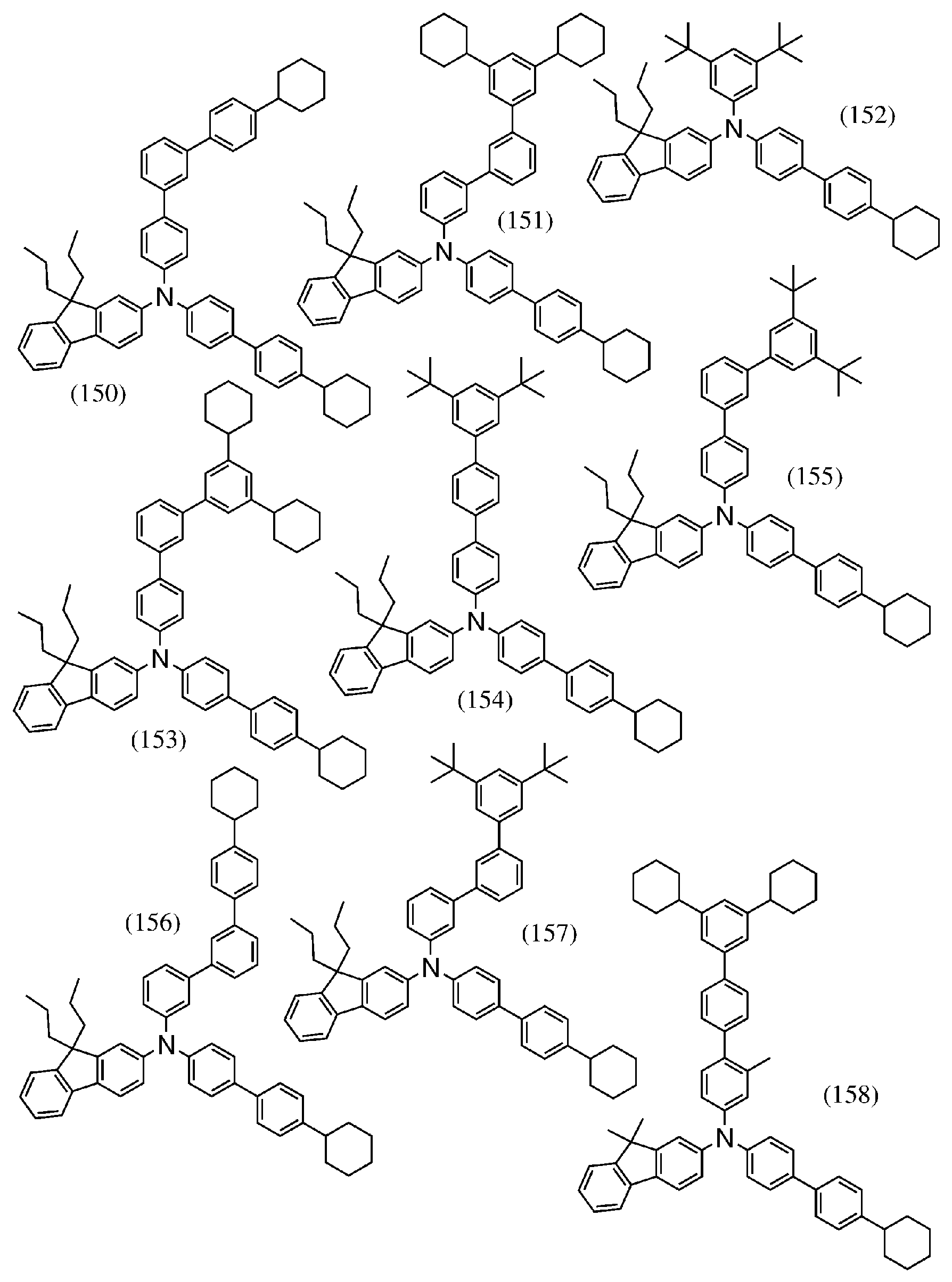


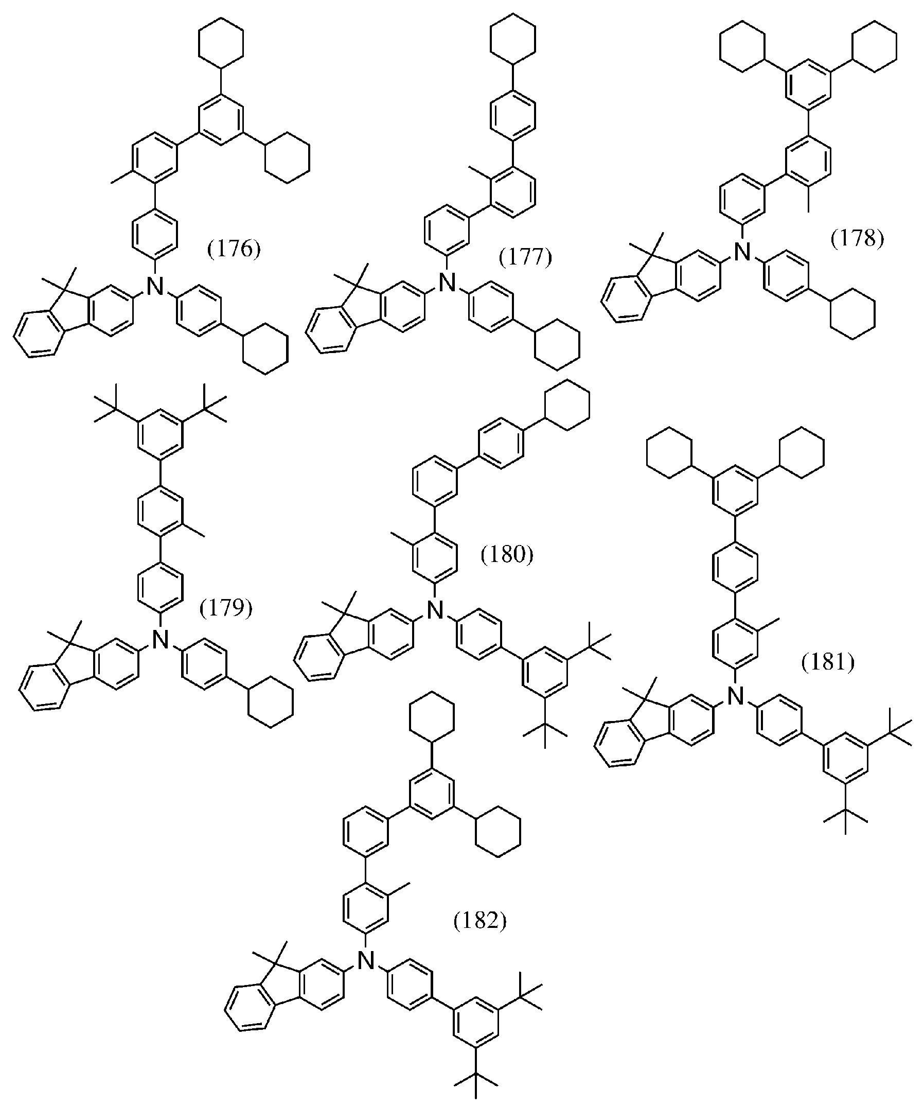


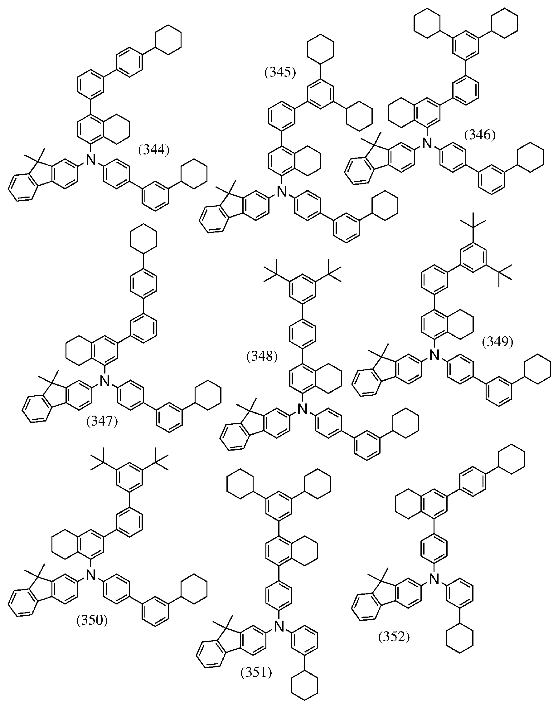


Als Nächstes wird ein Beispiel für ein Syntheseverfahren der vorstehend beschriebenen Monoamin-Verbindung beschrieben. Es sei angemerkt, dass das folgende Verfahren nur ein Beispiel für ein Syntheseverfahren der vorliegenden Erfindung ist und das Syntheseverfahren nicht darauf beschränkt ist.

Wie in dem folgenden Syntheseschema gezeigt, werden 9,9-disubstituiertes 9H-Fluorenylamin (A) und organische Halogenide (X1) und (X2) unter Verwendung eines Metallkatalysators, eines Metalls oder einer Metallverbindung in Anwesenheit einer Base gekoppelt, so dass die organische Verbindung, die durch die allgemeine Formel (G1) dargestellt wird, erhalten werden kann.

In dem vorstehenden Syntheseschema stellen Ar1 und Ar2 jeweils unabhängig voneinander einen Substituenten mit einem substituierten oder unsubstituierten Benzolring oder einen Substituenten dar, in dem zwei oder drei Benzolringe aneinander gebunden sind. Es sei angemerkt, dass Ar1 und/oder Ar2 eine oder mehrere Kohlenwasserstoff-Gruppen aufweisen/aufweist, die 1 bis 12 Kohlenstoffatome aufweisen, die jeweils nur durch die sp3-Hybridorbitale eine Bindung bilden, die Gesamtzahl der Kohlenstoffatome in der/den Kohlenwasserstoff-Gruppe/n in Ar1 und Ar2 8 oder mehr ist und die Gesamtzahl der Kohlenstoffatome in der/den Kohlenwasserstoff-Gruppe/n in Ar1 oder Ar2 6 oder mehr ist. Es sei angemerkt, dass in dem Fall, in dem eine Vielzahl von geradkettigen Alkyl-Gruppen, die jeweils 1 oder 2 Kohlenstoffatome aufweisen, als Kohlenwasserstoff-Gruppen in Ar1 und Ar2 enthalten ist, die geradkettigen Alkyl-Gruppen aneinander gebunden sein können, um einen Ring zu bilden. In der allgemeinen Formel (G1) stellen ferner R1 und R2 jeweils unabhängig voneinander eine Alkyl-Gruppe mit 1 bis 4 Kohlenstoffatomen dar. Es sei angemerkt, dass R1 und R2 aneinander gebunden sein können, um einen Ring zu bilden. R3 stellt eine Alkyl-Gruppe mit 1 bis 4 Kohlenstoffatomen dar, und u ist eine ganze Zahl von 0 bis 4. Ferner stellt X ein Halogenelement oder eine Triflat-Gruppe dar.In the above synthesis scheme, Ar 1 and Ar 2 each independently represent a substituent having a substituted or unsubstituted benzene ring or a substituent in which two or three benzene rings are bonded to each other. It should be noted that Ar 1 and / or Ar 2 have / has one or more hydrocarbon groups which have 1 to 12 carbon atoms, each of which only forms a bond through the sp 3 hybrid orbitals, the total number of carbon atoms in the (s) Hydrocarbon group (s) in Ar 1 and
In dem Fall, in dem die vorstehende Synthesereaktion unter Verwendung einer Buchwald-Hartwig-Reaktion durchgeführt wird, stellt X ein Halogenelement oder eine Triflat-Gruppe dar. Als Halogenelement wird Jod, Brom oder Chlor bevorzugt. In dieser Reaktion wird ein Palladiumkatalysator, der einen Palladiumkomplex oder eine Palladiumverbindung, wie z. B. Bis(dibenzylidenaceton)palladium(0) oder Allylpalladium(II)chloriddimer, und einen Liganden, der sich mit dem Palladiumkomplex oder der Palladiumverbindung koordiniert, wie z. B. Tri(tert-butyl)phosphin, Di-tert-butyl(1-methyl-2,2-diphenylcyclopropyl)phosphin oder Tricyclohexylphosphin, beinhaltet, verwendet. Als Base können eine organische Base, wie z. B. Natrium-tert-butoxid, eine anorganische Base, wie z. B. Cäsiumcarbonat, und dergleichen verwendet werden. In dem Fall, in dem ein Lösungsmittel verwendet wird, kann Toluol, Xylol, 1,3,5-Trimethylbenzol (Mesitylen) oder dergleichen verwendet werden. Wenn die Reaktionstemperatur auf höher als oder gleich 120°C eingestellt wird, schreitet ferner die Reaktion zwischen der Aryl-Gruppe, die ein Halogenelement mit einer kleinen periodischen Zahl, wie z. B. Chlor, beinhaltet, und einem Amin in kurzer Zeit und in hoher Ausbeute fort; daher wird vorzugsweise Xylol oder 1,3,5-Trimethylbenzol mit hoher Wärmebeständigkeit verwendet.In the case where the above synthesis reaction is carried out using a Buchwald-Hartwig reaction, X represents a halogen element or a triflate group. As the halogen element, iodine, bromine or chlorine is preferable. In this reaction, a palladium catalyst comprising a palladium complex or a palladium compound, such as. B. bis (dibenzylideneacetone) palladium (0) or allylpalladium (II) chloride dimer, and a ligand that coordinates with the palladium complex or the palladium compound, such as. Tri (tert-butyl) phosphine, di-tert-butyl (1-methyl-2,2-diphenylcyclopropyl) phosphine, or tricyclohexylphosphine are used. As the base, an organic base, such as. B. sodium tert-butoxide, an inorganic base, such as. B. cesium carbonate, and the like can be used. In the case where a solvent is used, toluene, xylene, 1,3,5-trimethylbenzene (mesitylene) or the like can be used. Further, when the reaction temperature is set higher than or equal to 120 ° C, the reaction between the aryl group, which is a halogen element having a small periodic number such as. B. chlorine, and an amine in a short time and in high yield; therefore, xylene or 1,3,5-trimethylbenzene having high heat resistance is preferably used.
Wenn die vorstehende Synthese durch die Ullmann-Reaktion durchgeführt wird, stellt X ein Halogenelement dar. Als Halogenelement wird Jod, Brom oder Chlor bevorzugt. Als Katalysator wird Kupfer oder eine KupferVerbindung verwendet. Es sei angemerkt, dass vorzugsweise Kupfer(I)iodid oder Kupfer(II)acetat verwendet wird. Beispiele für die Base umfassen eine anorganische Base, wie z. B. Kaliumcarbonat. Als Lösungsmittel kann 1,3-Dimethyl-3,4,5,6-tetrahydro-2(1 H)-pyrimidinon (DMPU), N-Methyl-2-pyrrolidon (NMP), Toluol, Xylol, 1,3,5-Trimethylbenzol oder dergleichen verwendet werden. Bei der Ullmann-Reaktion kann dann, wenn die Reaktionstemperatur bei 100°C oder höher liegt, eine Zielsubstanz in kürzerer Zeit und in höherer Ausbeute erhalten werden; deshalb wird vorzugsweise DMPU, NMP oder 1,3,5-Trimethylbenzol verwendet, die jeweils einen hohen Siedepunkt aufweisen. Da die Reaktionstemperatur bevorzugter bei 150 °C oder höher liegt, wird ferner DMPU bevorzugter verwendet.When the above synthesis is carried out by the Ullmann reaction, X represents a halogen element. As the halogen element, iodine, bromine or chlorine is preferred. Copper or a copper compound is used as a catalyst. It should be noted that copper (I) iodide or copper (II) acetate is preferably used. Examples of the base include an inorganic base such as. B. potassium carbonate. 1,3-Dimethyl-3,4,5,6-tetrahydro-2 (1H) -pyrimidinone (DMPU), N-methyl-2-pyrrolidone (NMP), toluene, xylene, 1,3,5 Trimethylbenzene or the like can be used. In the Ullmann reaction, if the reaction temperature is 100 ° C. or higher, a target substance can be obtained in a shorter time and in a higher yield; therefore, DMPU, NMP or 1,3,5-trimethylbenzene, each of which has a high boiling point, is preferably used. Further, since the reaction temperature is more preferably 150 ° C or higher, DMPU is more preferably used.
Auf die vorstehende Weise kann die organische Verbindung, die durch die allgemeine Formel (G1) dargestellt wird, synthetisiert werden.In the above manner, the organic compound represented by the general formula (G1) can be synthesized.
(Ausführungsform 2)(Embodiment 2)
Die EL-Schicht
Es sei angemerkt, dass
Die organische Verbindung weist eine gute Lochtransporteigenschaft auf und ist somit für die Lochtransportschicht
Außerdem kann die organische Verbindung einer Ausführungsform der vorliegenden Erfindung als Wirtsmaterial verwendet werden. Des Weiteren können das Lochtransportmaterial und ein Elektronentransportmaterial derart durch Co-Verdampfung abgeschieden werden, dass ein Exciplex durch das Elektronentransportmaterial und das Lochtransportmaterial gebildet wird. Der Exciplex mit einer geeigneten Emissionswellenlänge ermöglicht eine effiziente Energieübertragung auf das Licht emittierende Material, was zum Erhalt einer Licht emittierenden Vorrichtung mit hoher Effizienz und langer Lebensdauer führt.In addition, the organic compound of one embodiment of the present invention can be used as a host material. Furthermore, the hole transport material and an electron transport material can be deposited by co-evaporation in such a way that an exciplex is formed by the electron transport material and the hole transport material. The exciplex with a suitable emission wavelength enables energy to be efficiently transferred to the light-emitting material, resulting in obtaining a light-emitting device with high efficiency and long life.
Da die organische Verbindung einer Ausführungsform der vorliegenden Erfindung einen niedrigen Brechungsindex aufweist, kann die Licht emittierende Vorrichtung, bei der die organische Verbindung in der EL-Schicht verwendet wird, eine hohe externe Quanteneffizienz aufweisen.Since the organic compound of one embodiment of the present invention has a low refractive index, the light-emitting device using the organic compound in the EL layer can have a high external quantum efficiency.
Als Nächstes werden Beispiele für spezifische Strukturen und Materialien der vorstehend beschriebenen Licht emittierenden Vorrichtung beschrieben. Die Licht emittierende Vorrichtung einer Ausführungsform der vorliegenden Erfindung umfasst, wie vorstehend beschrieben, zwischen dem Paar von Elektroden der ersten Elektrode
Die erste Elektrode
Obwohl die EL-Schicht
Die Lochinjektionsschicht
Als Substanz mit einer Akzeptoreigenschaft kann eine Verbindung mit einer elektronenziehenden Gruppe (einer Halogen-Gruppe oder einer Cyano-Gruppe) verwendet werden; beispielsweise kann 7,7,8,8-Tetracyano-2,3,5,6-tetrafluorchinodimethan (Abkürzung: F4-TCNQ), Chloranil, 2,3,6,7,10,11-Hexacyano-1,4,5,8,9,12-hexaazatriphenylen (Abkürzung: HAT-CN), 1,3,4,5,7,8-Hexafluortetracyano-naphthochinodimethan (Abkürzung: F6-TCNNQ) oder 2-(7-Dicyanomethylen-1,3,4,5,6,8,9,10-octafluor-7H-pyren-2-yliden)malononitril verwendet werden. Eine Verbindung, in der elektronenziehende Gruppen an einen kondensierten aromatischen Ring mit einer Vielzahl von Heteroatomen gebunden sind, wie z. B. HAT-CN, wird besonders bevorzugt, da sie thermisch stabil ist. Ein [3]Radialen-Derivat, das eine elektronenziehende Gruppe (insbesondere eine Cyano-Gruppe oder eine Halogen-Gruppe, wie z. B. eine Fluor-Gruppe) umfasst, weist eine sehr hohe Elektronenakzeptoreigenschaft auf und wird somit bevorzugt. Spezifische Beispiele umfassen α,α',α''-1,2,3-Cyclopropantriylidentris[4-cyano-2,3,5,6-tetrafluorbenzolacetonitril], α, α',α''-1,2,3-Cyclopropantriylidentris[2,6-dichlor-3,5-difluor-4-(trifluormethyl)benzolacetonitril] und α, α',α''-1,2,3-Cyclopropantriylidentris[2,3,4,5,6-pentafluorbenzolacetonitril]. Als Substanz mit einer Akzeptoreigenschaft kann neben den vorstehenden organschen Verbindungen Molybdänoxid, Vanadiumoxid, Rutheniumoxid, Wolframoxid, Manganoxid oder dergleichen verwendet werden. Alternativ kann die Lochinjektionsschicht
Alternativ kann ein Verbundmaterial, bei dem ein Material mit einer Lochtransporteigenschaft eine beliebige der vorstehend erwähnten Substanzen mit einer Akzeptoreigenschaft enthält, für die Lochinjektionsschicht
Als Material mit einer Lochtransporteigenschaft, das für das Verbundmaterial verwendet wird, können verschiedene organische Verbindungen, wie z. B. aromatische Amin-Verbindungen, Carbazol-Derivate, aromatische Kohlenwasserstoffe und hochmolekulare Verbindungen (z. B. Oligomere, Dendrimere oder Polymere) verwendet werden. Es sei angemerkt, dass das Material mit einer Lochtransporteigenschaft, das für das Verbundmaterial verwendet wird, vorzugsweise eine Löcherbeweglichkeit von 1 × 10⁻⁶ cm2/Vs oder höher aufweist. Organische Verbindungen, die als Material mit einer Lochtransporteigenschaft in dem Verbundmaterial verwendet werden können, werden insbesondere nachstehend angegeben.As the material having a hole transport property used for the composite material, various organic compounds such as. B. aromatic amine compounds, carbazole derivatives, aromatic hydrocarbons and high molecular weight compounds (e.g. oligomers, dendrimers or polymers) can be used. Note that the material having a hole transport property used for the composite material preferably has a hole mobility of 1 × 10 -6 cm 2 / Vs or higher. Organic compounds that can be used as a material having a hole transport property in the composite material are specifically given below.
Beispiele für die aromatischen Amin-Verbindungen, die für das Verbundmaterial verwendet werden können, umfassen N,N'-Di(p-tolyl)-N,N'-diphenyl-p-phenylendiamin (Abkürzung: DTDPPA), 4,4'-Bis[N-(4-diphenylaminophenyl)-N-phenylamino]biphenyl (Abkürzung: DPAB), N,N'-Bis{4-[bis(3-methylphenyl)amino]phenyl}-N,N'-diphenyl-(1,1'-biphenyl)-4,4'-diamin (Abkürzung: DNTPD) und 1,3,5-Tris[N-(4-diphenylaminophenyl)-N-phenylamino]benzol (Abkürzung: DPA3B). Spezifische Beispiele für das Carbazol-Derivat umfassen 3-[N-(9-Phenylcarbazol-3-yl)-N-phenylamino]-9-phenylcarbazol (Abkürzung: PCzPCA1), 3,6-Bis[N-(9-phenylcarbazol-3-yl)-N-phenylamino]-9-phenylcarbazol (Abkürzung: PCzPCA2), 3-[N-(1-Naphthyl)-N-(9-phenylcarbazol-3-yl)amino]-9-phenylcarbazol (Abkürzung: PCzPCN1), 4,4'-Di(N-carbazolyl)biphenyl (Abkürzung: CBP), 1,3,5-Tris[4-(N-carbazolyl)phenyl]benzol (Abkürzung: TCPB), 9-[4-(10-Phenylanthracen-9-yl)phenyl]-9H-carbazol (Abkürzung: CzPA) und 1,4-Bis[4-(N-carbazolyl)phenyl]-2,3,5,6-tetraphenylbenzol. Beispiele für den aromatischen Kohlenwasserstoff umfassen 2-tert-Butyl-9,10-di(2-naphthyl)anthracen (Abkürzung: t-BuDNA), 2-tert-Butyl-9,10-di(1-naphthyl)anthracen, 9,10-Bis(3,5-diphenylphenyl)anthracen (Abkürzung: DPPA), 2-tert-Butyl-9,10-bis(4-phenylphenyl)anthracen (Abkürzung: t-BuDBA), 9,10-Di(2-naphthyl)anthracen (Abkürzung: DNA), 9,10-Diphenylanthracen (Abkürzung: DPAnth), 2-tert-Butylanthracen (Abkürzung: t-BuAnth), 9,10-Bis(4-methyl-1-naphthyl)anthracen (Abkürzung: DMNA), 2-tert-Butyl-9,10-bis[2-(1-naphthyl)phenyl]anthracen, 9,10-Bis[2-(1-naphthyl)phenyl]anthracen, 2,3,6,7-Tetramethyl-9,1 0-di(1 -naphthyl)anthracen, 2,3,6,7-Tetramethyl-9,10-di(2-naphthyl)anthracen, 9,9'-Bianthryl, 10,10'-Diphenyl-9,9'-bianthryl, 10,10'-Bis(2-phenylphenyl)-9,9'-bianthryl, 10,10'-Bis[(2,3,4,5,6-pentaphenyl)phenyl]-9,9'-bianthryl, Anthracen, Tetracen, Rubren, Perylen und 2,5,8,11-Tetra(tert-butyl)perylen. Weitere Beispiele umfassen Pentacen und Coronen. Der aromatische Kohlenwasserstoff kann ein Vinyl-Gerüst aufweisen. Beispiele für den aromatischen Kohlenwasserstoff mit einer Vinyl-Gruppe umfassen 4,4'-Bis(2,2-diphenylvinyl)biphenyl (Abkürzung: DPVBi) und 9,10-Bis[4-(2,2-diphenylvinyl)phenyl]anthracen (Abkürzung: DPVPA). Es sei angemerkt, dass die organische Verbindung einer Ausführungsform der vorliegenden Erfindung auch verwendet werden kann.Examples of the aromatic amine compounds that can be used for the composite material include N, N'-di (p-tolyl) -N, N'-diphenyl-p-phenylenediamine (abbreviation: DTDPPA), 4,4'- Bis [N- (4-diphenylaminophenyl) -N-phenylamino] biphenyl (abbreviation: DPAB), N, N'-bis {4- [bis (3-methylphenyl) amino] phenyl} -N, N'-diphenyl- ( 1,1'-biphenyl) -4,4'-diamine (abbreviation: DNTPD) and 1,3,5-tris [N- (4-diphenylaminophenyl) -N-phenylamino] benzene (abbreviation: DPA3B). Specific examples of the carbazole derivative include 3- [N- (9-phenylcarbazol-3-yl) -N-phenylamino] -9-phenylcarbazole (abbreviation: PCzPCA1), 3,6-bis [N- (9-phenylcarbazole- 3-yl) -N-phenylamino] -9-phenylcarbazole (abbreviation: PCzPCA2), 3- [N- (1-naphthyl) -N- (9-phenylcarbazol-3-yl) amino] -9-phenylcarbazole (abbreviation: PCzPCN1), 4,4'-di (N-carbazolyl) biphenyl (abbreviation: CBP), 1,3,5-tris [4- (N-carbazolyl) phenyl] benzene (abbreviation: TCPB), 9- [4- (10-phenylanthracen-9-yl) phenyl] -9H-carbazole (abbreviation: CzPA) and 1,4-bis [4- (N-carbazolyl) phenyl] -2,3,5,6-tetraphenylbenzene. Examples of the aromatic hydrocarbon include 2-tert-butyl-9,10-di (2-naphthyl) anthracene (abbreviation: t-BuDNA), 2-tert-butyl-9,10-di (1-naphthyl) anthracene, 9 , 10-bis (3,5-diphenylphenyl) anthracene (abbreviation: DPPA), 2-tert-butyl-9,10-bis (4-phenylphenyl) anthracene (abbreviation: t-BuDBA), 9,10-di (2 -naphthyl) anthracene (abbreviation: DNA), 9,10-diphenylanthracene (abbreviation: DPAnth), 2-tert-butylanthracene (abbreviation: t-BuAnth), 9,10-bis (4-methyl-1-naphthyl) anthracene ( Abbreviation: DMNA), 2-tert-butyl-9,10-bis [2- (1-naphthyl) phenyl] anthracene, 9,10-bis [2- (1-naphthyl) phenyl] anthracene, 2,3,6 , 7-tetramethyl-9,1 0-di (1-naphthyl) anthracene, 2,3,6,7-tetramethyl-9,10-di (2-naphthyl) anthracene, 9,9'-bianthryl, 10.10 '-Diphenyl-9,9'-bianthryl, 10,10'-bis (2-phenylphenyl) -9,9'-bianthryl, 10,10'-bis [(2,3,4,5,6-pentaphenyl) phenyl] -9,9'-bianthryl, anthracene, tetracene, rubrene, perylene and 2,5,8,11-tetra (tert-butyl) perylene. Other examples include pentacene and coronene. The aromatic hydrocarbon can have a vinyl backbone. Examples of the aromatic hydrocarbon having a vinyl group include 4,4'-bis (2,2-diphenylvinyl) biphenyl (abbreviation: DPVBi) and 9,10-bis [4- (2,2-diphenylvinyl) phenyl] anthracene ( Abbreviation: DPVPA). It should be noted that the organic compound of one embodiment of the present invention can also be used.
Weitere Beispiele umfassen hochmolekulare Verbindungen, wie z. B. Poly(N-vinylcarbazol) (Abkürzung: PVK), Poly(4-vinyltriphenylamin) (Abkürzung: PVTPA), Poly[N-(4-{N'-[4-(4-diphenylamino)phenyl]phenyl-N'-phenylamino}phenyl)methacrylamid] (Abkürzung: PTPDMA) und Poly[N,N'-bis(4-butylphenyl)-N,N'-bis(phenyl)benzidin] (Abkürzung: Poly-TPD).Other examples include high molecular weight compounds such as. B. Poly (N-vinylcarbazole) (abbreviation: PVK), poly (4-vinyltriphenylamine) (abbreviation: PVTPA), poly [N- (4- {N '- [4- (4-diphenylamino) phenyl] phenyl] -N) '-phenylamino} phenyl) methacrylamide] (abbreviation: PTPDMA) and poly [N, N'-bis (4-butylphenyl) -N, N'-bis (phenyl) benzidine] (abbreviation: Poly-TPD).
Das Material mit einer Lochtransporteigenschaft, das in dem Verbundmaterial verwendet wird, weist bevorzugter ein Carbazol-Gerüst, ein Dibenzofuran-Gerüst, ein Dibenzothiophen-Gerüst oder ein Anthracen-Gerüst auf. Insbesondere kann ein aromatisches Amin mit einem Substituenten, der einen Dibenzofuranring oder einen Dibenzothiophenring umfasst, ein aromatisches Monoamin, das einen Naphthalinring umfasst, oder ein aromatisches Monoamin, in dem eine 9-Fluorenyl-Gruppe über eine Arylen-Gruppe an Stickstoff eines Amins gebunden ist, verwendet werden. Es sei angemerkt, dass die zweite organische Verbindung mit einer N,N-Bis(4-biphenyl)aminogruppe bevorzugt wird, da eine Licht emittierende Vorrichtung mit langer Lebensdauer hergestellt werden kann. Spezifische Beispiele für die zweite organische Verbindung umfassen N-(4-Biphenyl)-6,N-diphenylbenzo[b]naphtho[1,2-d]furan-8-amin (Abkürzung: BnfABP), N,N-Bis(4-biphenyl)-6-phenylbenzo[b]naphtho[1,2-d]furan-8-amin (Abkürzung: BBABnf), 4,4'-Bis(6-phenylbenzo[b]naphtho[1,2-d]furan-8-yl)-4''-phenyltriphenylamin (Abkürzung: BnfBB1BP), N,N-Bis(4-biphenyl)benzo[b]naphtho[1,2-d]furan-6-amin (Abkürzung: BBABnf(6)), N,N-Bis(4-biphenyl)benzo[b]naphtho[1,2-d]furan-8-amin (Abkürzung: BBABnf(8)), N,N-Bis(4-biphenyl)benzo[b]naphtho[2,3-d]furan-4-amin (Abkürzung: BBABnf(II) (4)), N,N-Bis[4-(dibenzofuran-4-yl)phenyl]-4-amino-p-terphenyl (Abkürzung: DBfBB1TP), N-[4-(Dibenzothiophen-4-yl)phenyl]-N-phenyl-4-biphenylamin (Abkürzung: ThBA1BP), 4-(2-Naphthyl)-4',4''-diphenyltriphenylamin (Abkürzung: BBAβNB), 4-[4-(2-Naphthyl)phenyl]-4',4''-diphenyltriphenylamin (Abkürzung: BBAβNBi), 4,4'-Diphenyl-4''-(6;1'-binaphthyl-2-yl)triphenylamin (Abkürzung: BBAαNβNB), 4,4'-Diphenyl-4''-(7;1'-binaphthyl-2-yl)triphenylamin (Abkürzung: BBAαNβNB-03), 4,4'-Diphenyl-4''-(7-phenyl)naphthyl-2-yltriphenylamin (Abkürzung: BBAPβNB-03), 4,4'-Diphenyl-4''-(6;2-binaphthyl-2-yl)triphenylamin (Abkürzung: BBA(βN2)B), 4,4'-Diphenyl-4''-(7;2'-binaphthyl-2-yl)triphenylamin (Abkürzung: BBA(βN2)B-03), 4,4'-Diphenyl-4''-(4;2'-binaphthyl-1-yl)triphenylamin (Abkürzung: BBAβNαNB), 4,4'-Diphenyl-4''-(5;2'-binaphthyl-1-yl)triphenylamin (Abkürzung: BBAβNαNB-02), 4-(4-Biphenylyl)-4'-(2-naphthyl)-4''-phenyltriphenylamin (Abkürzung: TPBiAβNB), 4-(3-Biphenylyl)-4'-[4-(2-naphthyl)phenyl]-4''-phenyltriphenylamin (Abkürzung: mTPBiAβNBi), 4-(4-Biphenylyl)-4'-[4-(2-naphthyl)phenyl]-4''-phenyltriphenylamin (Abkürzung: TPBiAβNBi), 4-Phenyl-4'-(1-naphthyl)triphenylamin (Abkürzung: αNBA1BP), 4,4'-Bis(1-naphthyl)triphenylamin (Abkürzung: αNBB1BP), 4,4'-Diphenyl-4''-[4'-(carbazol-9-yl)biphenyl-4-yl]triphenylamin (Abkürzung: YGTBi1BP), 4'-[4-(3-Phenyl-9H-carbazol-9-yl)phenyl]tris(1,1'-biphenyl-4-yl)amin (Abkürzung: YGTBi1BP-02), 4-[4'-(Carbazol-9-yl)biphenyl-4-yl]-4'-(2-naphthyl)-4''-phenyltriphenylamin (Abkürzung: YGTBißNB), N-[4-(9-Phenyl-9H-carbazol-3-yl)phenyl]-N-[4-(1-naphthyl)phenyl]-9,9'-spirobi[9H-fluoren]-2-amin (Abkürzung: PCBNBSF), N,N-Bis ([1,1 ‚-biphenyl]-4-yl)-9,9‘-spirobi[9H-fluoren]-2-amin (Abkürzung: BBASF), N,N-Bis([1,1 ‚-biphenyl]-4-yl)-9,9‘-spirobi[9H-fluoren]-4-amin (Abkürzung: BBASF(4)), N-(1,1'-Biphenyl-2-yl)-N-(9,9-dimethyl-9H-fluoren-2-yl)-9,9'-spirobi[9H-fluoren]-4-amin (Abkürzung: oFBiSF), N-(4-Biphenyl)-N-(9,9-dimethyl-9H-fluoren-2-yl)dibenzofuran-4-amin (Abkürzung: FrBiF), N-[4-(1-Naphthyl)phenyl]-N-[3-(6-phenyld ibenzofuran-4-yl)phenyl]-1-naphthylam in (Abkürzung: mPDBfBNBN), 4-Phenyl-4'-(9-phenylfluoren-9-yl)triphenylamin (Abkürzung: BPAFLP), 4-Phenyl-3'-(9-phenylfluoren-9-yl)triphenylamin (Abkürzung: mBPAFLP), 4-Phenyl-4'-[4-(9-phenylfluoren-9-yl)phenyl]triphenylamin (Abkürzung: BPAFLBi), 4-Phenyl-4'-(9-phenyl-9H-carbazol-3-yl)triphenylamin (Abkürzung: PCBA1BP), 4,4'-Diphenyl-4''-(9-phenyl-9H-carbazol-3-yl)triphenylamin (Abkürzung: PCBBi1BP), 4-(1-Naphthyl)-4'-(9-phenyl-9H-carbazol-3-yl)triphenylamin (Abkürzung: PCBANB), 4,4'-Di(1-naphthyl)-4''-(9-phenyl-9H-carbazol-3-yl)triphenylamin (Abkürzung: PCBNBB), N-Phenyl-N-[ 4-(9-phenyl-9H-carbazol-3-yl)phenyl]-9, 9'-spirobi[9H-fluoren ]-2-amin (Abkürzung: PCBASF), N-(1,1'-Biphenyl-4-yl)-9,9-dimethyl-N-[4-(9-phenyl-9H-carbazol-3-yl)phenyl]-9H-fluoren-2-amin (Abkürzung: PCBBiF), N,N-Bis(9,9-dimethyl-9H-fluoren-2-yl)-9,9'-spirobi-9H-fluoren-4-amin, N,N-Bis(9,9-dimethyl-9H-fluoren-2-yl)-9,9'-spirobi-9H-fluoren-3-amin, N,N-Bis(9,9-dimethyl-9H-fluoren-2-yl)-9,9'-spirobi-9H-fluoren-2-amin und N,N-Bis(9,9-dimethyl-9H-fluoren-2-yl)-9,9'-spirobi-9H-fluoren-1-amin.The material having a hole transport property used in the composite material more preferably has a carbazole skeleton, a dibenzofuran skeleton, a dibenzothiophene skeleton or an anthracene skeleton. In particular, an aromatic amine having a substituent comprising a dibenzofuran ring or a dibenzothiophene ring, an aromatic monoamine comprising a naphthalene ring, or an aromatic monoamine in which a 9-fluorenyl group is bonded to nitrogen of an amine via an arylene group , be used. Note that the second organic compound having an N, N-bis (4-biphenyl) amino group is preferred because a light-emitting device with a long life can be manufactured. Specific examples of the second organic compound include N- (4-biphenyl) -6, N-diphenylbenzo [b] naphtho [1,2-d] furan-8-amine (abbreviation: BnfABP), N, N-bis (4 -biphenyl) -6-phenylbenzo [b] naphtho [1,2-d] furan-8-amine (abbreviation: BBABnf), 4,4'-bis (6-phenylbenzo [b] naphtho [1,2-d] furan-8-yl) -4 '' - phenyltriphenylamine (abbreviation: BnfBB1BP), N, N-bis (4-biphenyl) benzo [b] naphtho [1,2-d] furan-6-amine (abbreviation: BBABnf ( 6)), N, N-bis (4-biphenyl) benzo [b] naphtho [1,2-d] furan-8-amine (abbreviation: BBABnf (8)), N, N-bis (4-biphenyl) benzo [b] naphtho [2,3-d] furan-4-amine (Abbreviation: BBABnf (II) (4)), N, N-bis [4- (dibenzofuran-4-yl) phenyl] -4-amino -p-terphenyl (abbreviation: DBfBB1TP), N- [4- (dibenzothiophen-4-yl) phenyl] -N-phenyl-4-biphenylamine (abbreviation: ThBA1BP), 4- (2-naphthyl) -4 ', 4 '' -diphenyltriphenylamine (abbreviation: BBAβNB), 4- [4- (2-naphthyl) phenyl] -4 ', 4' '- diphenyltriphenylamine (abbreviation: BBAβNBi), 4,4'-diphenyl-4' '- (6 ; 1'-binaphthyl-2-yl) triphenylamine (abbreviation: BBAαNβNB), 4,4'-diphenyl-4 "- (7; 1'-binaphthyl-2-yl) triphenyl amine (abbreviation: BBAαNβNB-03), 4,4'-diphenyl-4 '' - (7-phenyl) naphthyl-2-yltriphenylamine (abbreviation: BBAPβNB-03), 4,4'-diphenyl-4 '' - ( 6; 2-binaphthyl-2-yl) triphenylamine (abbreviation: BBA (βN2) B), 4,4'-diphenyl-4 '' - (7; 2'-binaphthyl-2-yl) triphenylamine (abbreviation: BBA ( βN2) B-03), 4,4'-diphenyl-4 "- (4; 2'-binaphthyl-1-yl) triphenylamine (abbreviation: BBAβNαNB), 4,4'-diphenyl-4" - (5 ; 2'-binaphthyl-1-yl) triphenylamine (abbreviation: BBAβNαNB-02), 4- (4-biphenylyl) -4 '- (2-naphthyl) -4' '- phenyltriphenylamine (abbreviation: TPBiAβNB), 4- ( 3-biphenylyl) -4 '- [4- (2-naphthyl) phenyl] -4 "- phenyltriphenylamine (abbreviation: mTPBiAβNBi), 4- (4-biphenylyl) -4' - [4- (2-naphthyl) phenyl ] -4 '' - phenyltriphenylamine (abbreviation: TPBiAβNBi), 4-phenyl-4 '- (1-naphthyl) triphenylamine (abbreviation: αNBA1BP), 4,4'-bis (1-naphthyl) triphenylamine (abbreviation: αNBB1BP), 4,4'-Diphenyl-4 "- [4 '- (carbazol-9-yl) biphenyl-4-yl] triphenylamine (abbreviation: YGTBi1BP), 4' - [4- (3-phenyl-9H-carbazole- 9-yl) phenyl] tris (1,1'-biphenyl-4-yl) amine (abbreviation: YGTBi1BP-02), 4- [4 '- (Carba zol-9-yl) biphenyl-4-yl] -4 '- (2-naphthyl) -4 "-phenyltriphenylamine (abbreviation: YGTBißNB), N- [4- (9-phenyl-9H-carbazol-3-yl ) phenyl] -N- [4- (1-naphthyl) phenyl] -9,9'-spirobi [9H-fluorene] -2-amine (abbreviation: PCBNBSF), N, N-bis ([1,1 '- biphenyl] -4-yl) -9,9'-spirobi [9H-fluorene] -2-amine (abbreviation: BBASF), N, N-bis ([1,1'-biphenyl] -4-yl) -9 , 9'-spirobi [9H-fluorene] -4-amine (abbreviation: BBASF (4)), N- (1,1'-biphenyl-2-yl) -N- (9,9-dimethyl-9H-fluorene -2-yl) -9,9'-spirobi [9H-fluorene] -4-amine (abbreviation: oFBiSF), N- (4-biphenyl) -N- (9,9-dimethyl-9H-fluorene-2- yl) dibenzofuran-4-amine (abbreviation: FrBiF), N- [4- (1-naphthyl) phenyl] -N- [3- (6-phenyldibenzofuran-4-yl) phenyl] -1-naphthylam in (abbreviation : mPDBfBNBN), 4-phenyl-4 '- (9-phenylfluoren-9-yl) triphenylamine (abbreviation: BPAFLP), 4-phenyl-3' - (9-phenylfluoren-9-yl) triphenylamine (abbreviation: mBPAFLP), 4-phenyl-4 '- [4- (9-phenylfluoren-9-yl) phenyl] triphenylamine (abbreviation: BPAFLBi), 4-phenyl-4' - (9-phenyl-9H-carbazol-3-yl) triphenylamine ( Abbreviation: PCBA1BP), 4,4'-diphenyl-4 '' - (9-phenyl- 9H-carbazol-3-yl) triphenylamine (abbreviation: PCBBi1BP), 4- (1-naphthyl) -4 '- (9-phenyl-9H-carbazol-3-yl) triphenylamine (abbreviation: PCBANB), 4,4' -Di (1-naphthyl) -4 '' - (9-phenyl-9H-carbazol-3-yl) triphenylamine (abbreviation: PCBNBB), N-phenyl-N- [4- (9-phenyl-9H-carbazole- 3-yl) phenyl] -9, 9'-spirobi [9H-fluorene] -2-amine (abbreviation: PCBASF), N- (1,1'-biphenyl-4-yl) -9,9-dimethyl-N - [4- (9-phenyl-9H-carbazol-3-yl) phenyl] -9H-fluorene-2-amine (abbreviation: PCBBiF), N, N-bis (9,9-dimethyl-9H-fluorene-2 -yl) -9,9'-spirobi-9H-fluorene-4-amine, N, N-bis (9,9-dimethyl-9H-fluoren-2-yl) -9,9'-spirobi-9H-fluorene -3-amine, N, N-bis (9,9-dimethyl-9H-fluorene-2-yl) -9,9'-spirobi-9H-fluorene-2-amine and N, N-bis (9.9 -dimethyl-9H-fluoren-2-yl) -9,9'-spirobi-9H-fluoren-1-amine.
Es sei angemerkt, dass das Material mit einer Lochtransporteigenschaft, das in dem Verbundmaterial verwendet wird, bevorzugter ein relativ tiefes HOMO-Niveau höher als oder gleich -5,7 eV und niedriger als oder gleich -5,4 eV aufweist. Wenn das Material mit einer Lochtransporteigenschaft, das ein relativ tiefes HOMO-Niveau aufweist, in dem Verbundmaterial verwendet wird, können Löcher leicht in die Lochtransportschicht
Es sei angemerkt, dass auch die bei der Ausführungsform
Indem das vorstehende Verbundmaterial mit einem Alkalimetallfluorid oder einem Erdalkalimetallfluorid gemischt wird (der Anteil an Fluoratomen in einer Schicht, in der das gemischte Material verwendet wird, ist bevorzugt größer als oder gleich 20 %), kann der Brechungsindex der Schicht verringert werden. Dadurch kann auch eine Schicht mit niedrigem Brechungsindex in der EL-Schicht
Die Ausbildung der Lochinjektionsschicht
Die Lochtransportschicht
In dem Fall, in dem ein anderes Material als die bei der Ausführungsform 1 beschriebene Monoamin-Verbindung für die Lochtransportschicht
Die Licht emittierende Schicht
Als Licht emittierende Substanz können fluoreszierende Substanzen, phosphoreszierende Substanzen, Substanzen, die eine thermisch aktivierte, verzögerte Fluoreszenz (thermally activated delayed fluorescence, TADF) emittieren, oder weitere Licht emittierende Substanzen verwendet werden. Es sei angemerkt, dass eine Ausführungsform der vorliegenden Erfindung bevorzugter in dem Fall verwendet wird, in dem die Licht emittierende Schicht
Beispiele für das Material, das als fluoreszierende Substanz in der Licht emittierenden Schicht
Die Beispiele umfassen 5,6-Bis[4-(10-phenyl-9-anthryl)phenyl]-2,2'-bipyridin (Abkürzung: PAP2BPy), 5,6-Bis[4'-(10-phenyl-9-anthryl)biphenyl-4-yl]-2,2'-bipyridin (Abkürzung: PAPP2BPy), N,N'-Diphenyl-N,N'-bis[4-(9-phenyl-9H-fluoren-9-yl)phenyl]pyren-1,6-diamin (Abkürzung: 1,6FLPAPrn), N,N'-Bis(3-methylphenyl)-N,N'-bis[3-(9-phenyl-9H-fluoren-9-yl)phenyl]pyren-1,6-diamin (Abkürzung: 1,6mMemFLPAPrn), N,N'-Bis[4-(9H-carbazol-9-yl)phenyl]-N,N'-diphenylstilben-4,4'-diamin (Abkürzung: YGA2S), 4-(9H-Carbazol-9-yl)-4'-(10-phenyl-9-anthryl)triphenylamin (Abkürzung: YGAPA), 4-(9H-Carbazol-9-yl)-4'-(9,10-diphenyl-2-anthryl)triphenylamin (Abkürzung: 2YGAPPA), N,9-Diphenyl-N-[4-(10-phenyl-9-anthryl)phenyl]-9H-carbazol-3-amin (Abkürzung: PCAPA), Perylen, 2,5,8,11-Tetra(tert-butyl)perylen (Abkürzung: TBP), 4-(10-Phenyl-9-anthryl)-4'-(9-phenyl-9H-carbazol-3-yl)triphenylamin (Abkürzung: PCBAPA), N,N''-(2-tert-Butylanthracen-9,10-diyldi-4,1-phenylen)bis[N,N,N'-triphenyl-1,4-phenylendiamin] (Abkürzung: DPABPA), N,9-Diphenyl-N-[4-(9,10-diphenyl-2-anthryl)phenyl]-9H-carbazol-3-amin (Abkürzung: 2PCAPPA), N-[4-(9,10-Diphenyl-2-anthryl)phenyl]-N,N',N'-triphenyl-1,4-phenylendiamin (Abkürzung: 2DPAPPA), N,N,N',N',N'',N'',N''',N'''-Octaphenyldibenzo[g,p]chrysen-2,7,10,15-tetraamin (Abkürzung: DBC1), Cumarin 30, N-(9,10-Diphenyl-2-anthryl)-N,9-diphenyl-9H-carbazol-3-amin (Abkürzung: 2PCAPA), N-[9,10-Bis(1,1'-biphenyl-2-yl)-2-anthryl]-N,9-diphenyl-9H-carbazol-3-amin (Abkürzung: 2PCABPhA), N-(9,10-Diphenyl-2-anthryl)-N,N,N'-triphenyl-1,4-phenylendiamin (Abkürzung: 2DPAPA), N-[9,1 0-Bis(1,1'-biphenyl-2-yl)-2-anthryl]-N,N',N'-triphenyl-1,4-phenylendiamin (Abkürzung: 2DPABPhA), 9,10-Bis(1,1'-biphenyl-2-yl)-N-[4-(9H-carbazol-9-yl)phenyl]-N-phenylanthracen-2-amin (Abkürzung: 2YGABPhA), N,N,9-Triphenylanthracen-9-amin (Abkürzung: DPhAPhA), Cumarin 545T, N,N'-Diphenylchinacridon (Abkürzung: DPQd), Rubren, 5,12-Bis(1,1'-biphenyl-4-yl)-6,11-diphenyltetracen (Abkürzung: BPT), 2-(2-{2-[4-(Dimethylamino)phenyl]ethenyl}-6-methyl-4H-pyran-4-yliden)propandinitril (Abkürzung: DCM1), 2-{2-Methyl-6-[2-(2,3,6,7-tetrahydro-1H,5H-benzo[ij]chinolizin-9-yl)ethenyl]-4H-pyran-4-ylidenlpropandinitril (Abkürzung: DCM2), N,N,N',N'-Tetrakis(4-methylphenyl)tetracen-5,11-diamin (Abkürzung: p-mPhTD), 7,14-Diphenyl-N,N,N',N'-tetrakis(4-methylphenyl)acenaphtho[1,2-a]fluoranthen-3,10-diamin (Abkürzung: p-mPhAFD), 2-{2-Isopropyl-6-[2-(1,1,7,7-tetramethyl-2,3,6,7-tetrahydro-1H,5H-benzo[ij]chinolizin-9-yl)ethenyl]-4H-pyran-4-yliden}propandinitril (Abkürzung: DCJTI), 2-{2-tert-Butyl-6-[2-(1,1,7,7-tetramethyl-2,3,6,7-tetrahydro-1H,5H-benzo[lj]chinolizin-9-yl)ethenyl]-4H-pyran-4-yliden}propandinitril (Abkürzung: DCJTB), 2-(2,6-Bis{2-[4-(dimethylamino)phenyl]ethenyl}-4H-pyran-4-yliden)propandinitril (Abkürzung: BisDCM), 2-{2,6-Bis[2-(8-methoxy-1,1,7,7-tetramethyl-2,3,6,7-tetrahydro-1H,5H-benzo[ij]chinolizin-9-yl)ethenyl]-4H-pyran-4-yliden}propandinitril (Abkürzung: BisDCJTM), N,N'-Diphenyl-N,N'-(1,6-pyren-diyl)bis[(6-phenylbenzo[b]naphtho[1,2-d]furan)-8-amin] (Abkürzung: 1,6BnfAPrn-03), 3,10-Bis[N-(9-phenyl-9H-carbazol-2-yl)-N-phenylamino]naphtho[2,3-b;6,7-b']bisbenzofuran (Abkürzung: 3,10PCA2Nbf(IV)-02) und 3,10-Bis[N-(dibenzofuran-3-yl)-N-phenylamino]naphtho[2,3-b;6,7-b']bisbenzofuran (Abkürzung: 3,10FrA2Nbf(IV)-02). Kondensierte aromatische Diamin-Verbindungen, typischerweise Pyrendiamin-Verbindungen, wie z. B. 1,6FLPAPrn, 1,6mMemFLPAPrn und 1,6BnfAPrn-03, werden wegen ihrer hohen Loch einfangenden Eigenschaften, hohen Emissionseffizienz und hohen Zuverlässigkeit besonders bevorzugt. Außerdem wird eine organische Verbindung mit einem Naphthobisbenzofuran-Gerüst oder einem Naphthobisbenzothiophen-Gerüst bevorzugt, da sie eine tiefe blaue Fluoreszenz emittiert und somit eine vorteilhafte blaue Licht emittierende Vorrichtung bereitgestellt werden kann. Eine organische Verbindung mit einem Naphthobisbenzofuran-Gerüst oder einem Naphthobisbenzothiophen-Gerüst, das zwei oder mehr Arylamin-Gerüste aufweist, wie 3,10PCA2Nbf(IV)-02 und 3,10FrA2Nbf(IV)-02, wird besonders bevorzugt, da sie eine hohe Leuchtdichtequantenausbeute aufweist. Eine organische Verbindung mit einem Naphthobisbenzofuran-Gerüst oder einem Naphthobisbenzothiophen-Gerüst, bei dem ein Dibenzofuran-Gerüst, ein Dibenzothiophen-Gerüst oder Carbazol-Gerüst an das Arylamin-Gerüst gebunden ist, wird stärker bevorzugt, da ihre Auskopplungseffizienz aufgrund der Molekülorientierung erhöht wird und sie eine hohe Zuverlässigkeit (besonders bei hoher Temperatur) aufweist. Es sei angemerkt, dass die organische Verbindung mit einem Naphthobisbenzofuran-Gerüst oder einem Naphthobisbenzothiophen-Gerüst eine sehr kleine Halbwertsbreite des PL-Spektrums von 30 nm oder weniger in einer Toluollösung aufweist. Deshalb ist es vorzuziehen, dass bei einer Ausführungsform der vorliegenden Erfindung, bei der eine Schicht mit niedrigem Brechungsindex den Mikrokavitätseffekt besonders effektiv ausübt, eine derartige Licht emittierende Substanz mit einer kleinen Halbwertsbreite verwendet wird.Examples include 5,6-bis [4- (10-phenyl-9-anthryl) phenyl] -2,2'-bipyridine (abbreviation: PAP2BPy), 5,6-bis [4 '- (10-phenyl-9 -anthryl) biphenyl-4-yl] -2,2'-bipyridine (abbreviation: PAPP2BPy), N, N'-diphenyl-N, N'-bis [4- (9-phenyl-9H-fluoren-9-yl ) phenyl] pyrene-1,6-diamine (abbreviation: 1,6FLPAPrn), N, N'-bis (3-methylphenyl) -N, N'-bis [3- (9-phenyl-9H-fluorene-9- yl) phenyl] pyrene-1,6-diamine (abbreviation: 1,6mMemFLPAPrn), N, N'-bis [4- (9H-carbazol-9-yl) phenyl] -N, N'-diphenylstilbene-4,4 '-diamin (abbreviation: YGA2S), 4- (9H-carbazol-9-yl) -4' - (10-phenyl-9-anthryl) triphenylamine (abbreviation: YGAPA), 4- (9H-carbazol-9-yl ) -4 '- (9,10-diphenyl-2-anthryl) triphenylamine (abbreviation: 2YGAPPA), N, 9-diphenyl-N- [4- (10-phenyl-9-anthryl) phenyl] -9H-carbazole- 3-amine (abbreviation: PCAPA), perylene, 2,5,8,11-tetra (tert-butyl) perylene (abbreviation: TBP), 4- (10-phenyl-9-anthryl) -4 '- (9- phenyl-9H-carbazol-3-yl) triphenylamine (abbreviation: PCBAPA), N, N '' - (2-tert-butylanthracene-9,10-diyldi-4,1-phenylene) to [N, N, N ' -triphenyl-1,4-phenylenediamine] (Abbreviation: DPAB PA), N, 9-Diphenyl-N- [4- (9,10-diphenyl-2-anthryl) phenyl] -9H-carbazol-3-amine (abbreviation: 2PCAPPA), N- [4- (9.10 -Diphenyl-2-anthryl) phenyl] -N, N ', N'-triphenyl-1,4-phenylenediamine (abbreviation: 2DPAPPA), N, N, N', N ', N ", N", N "", N "" - Octaphenyldibenzo [g, p] chrysen-2,7,10,15-tetraamine (abbreviation: DBC1), coumarin 30, N- (9,10-diphenyl-2-anthryl) -N , 9-diphenyl-9H-carbazol-3-amine (abbreviation: 2PCAPA), N- [9,10-bis (1,1'-biphenyl-2-yl) -2-anthryl] -N, 9-diphenyl- 9H-carbazol-3-amine (abbreviation: 2PCABPhA), N- (9,10-diphenyl-2-anthryl) -N, N, N'-triphenyl-1,4-phenylenediamine (abbreviation: 2DPAPA), N- [ 9.1 0-Bis (1,1'-biphenyl-2-yl) -2-anthryl] -N, N ', N'-triphenyl-1,4-phenylenediamine (abbreviation: 2DPABPhA), 9,10-bis (1,1'-biphenyl-2-yl) -N- [4- (9H-carbazol-9-yl) phenyl] -N-phenylanthracen-2-amine (abbreviation: 2YGABPhA), N, N, 9-triphenylanthracene -9-amine (abbreviation: DPhAPhA), coumarin 545T, N, N'-diphenylquinacridone (abbreviation: DPQd), rubrene, 5,12-bis (1,1'-biphenyl-4-yl) -6,11-diphenyltetracene (Abbreviation: BPT), 2- (2- {2- [4- (dimethylamino) phenyl ] ethenyl} -6-methyl-4H-pyran-4-ylidene) propanedinitrile (abbreviation: DCM1), 2- {2-methyl-6- [2- (2,3,6,7-tetrahydro-1H, 5H- benzo [ij] quinolizin-9-yl) ethenyl] -4H-pyran-4-ylidenlpropandinitril (abbreviation: DCM2), N, N, N ', N'-tetrakis (4-methylphenyl) tetracene-5,11-diamine ( Abbreviation: p-mPhTD), 7,14-diphenyl-N, N, N ', N'-tetrakis (4-methylphenyl) acenaphtho [1,2-a] fluoranthene-3,10-diamine (abbreviation: p-mPhAFD ), 2- {2-isopropyl-6- [2- (1,1,7,7-tetramethyl-2,3,6,7-tetrahydro-1H, 5H-benzo [ij] quinolizin-9-yl) ethenyl ] -4H-pyran-4-ylidene} propanedinitrile (abbreviation: DCJTI), 2- {2-tert-butyl-6- [2- (1,1,7,7-tetramethyl-2,3,6,7- tetrahydro-1H, 5H-benzo [lj] quinolizin-9-yl) ethenyl] -4H-pyran-4-ylidene} propanedinitrile (abbreviation: DCJTB), 2- (2,6-bis {2- [4- (dimethylamino ) phenyl] ethenyl} -4H-pyran-4-ylidene) propanedinitrile (abbreviation: BisDCM), 2- {2,6-bis [2- (8-methoxy-1,1,7,7-tetramethyl-2,3 , 6,7-tetrahydro-1H, 5H-benzo [ij] quinolizin-9-yl) ethenyl] -4H-pyran-4-ylidene} propanedinitrile (abbreviation: BisDCJTM), N, N'-diphenyl-N, N ' - (1,6-pyrene-diyl) bis [(6-ph enylbenzo [b] naphtho [1,2-d] furan) -8-amine] (abbreviation: 1,6BnfAPrn-03), 3,10-bis [N- (9-phenyl-9H-carbazol-2-yl) -N-phenylamino] naphtho [2,3-b; 6,7-b '] bisbenzofuran (abbreviation: 3,10PCA2Nbf (IV) -02) and 3,10-bis [N- (dibenzofuran-3-yl) - N-phenylamino] naphtho [2,3-b; 6,7-b '] bisbenzofuran (abbreviation: 3,10FrA2Nbf (IV) -02). Condensed aromatic diamine compounds, typically pyrenediamine compounds such as e.g. 1.6FLPAPrn, 1.6mMemFLPAPrn, and 1.6BnfAPrn-03 are particularly preferred because of their high hole trapping properties, high emission efficiency, and high reliability. In addition, an organic compound having a naphthobisbenzofuran skeleton or a naphthobisbenzothiophene skeleton is preferred because it emits deep blue fluorescence and thus an advantageous blue light emitting device can be provided. An organic compound having a naphthobisbenzofuran skeleton or a naphthobisbenzothiophene skeleton having two or more arylamine skeletons, such as 3,10PCA2Nbf (IV) -02 and 3,10FrA2Nbf (IV) -02, is particularly preferred because it is high Has luminance quantum yield. An organic compound having a naphthobisbenzofuran skeleton or a naphthobisbenzothiophene skeleton in which a dibenzofuran skeleton, a dibenzothiophene skeleton or carbazole skeleton is bonded to the arylamine skeleton is more preferred because its coupling-out efficiency is increased due to the molecular orientation it has a high reliability (especially at high temperatures). It should be noted that the organic compound having a naphthobisbenzofuran skeleton or a naphthobisbenzothiophene skeleton has a very small half width of the PL spectrum of 30 nm or less in a toluene solution. Therefore, it is preferable that in an embodiment of the present invention in which a layer having a low refractive index exerts the micro-cavity effect particularly effectively, such a light-emitting substance having a small half width is used.
Beispiele für das Material, das in dem Fall verwendet werden kann, in dem eine phosphoreszierende Substanz als Licht emittierende Substanz in der Licht emittierenden Schicht
Die Beispiele sind wie folgt: ein metallorganischer Iridiumkomplex mit einem 4H-Triazol-Gerüst, wie z. B. Tris{2-[5-(2-methylphenyl)-4-(2,6-dimethylphenyl)-4H-1,2,4-triazol-3-yl-kN2]phenyl-kC}iridium(III) (Abkürzung: [Ir(mpptz-dmp)3]), Tris(5-methyl-3,4-diphenyl-4H-1,2,4-triazolato)iridium(III) (Abkürzung: [Ir(Mptz)3]) und Tris[4-(3-biphenyl)-5-isopropyl-3-phenyl-4H-1,2,4-triazolato]iridium(III) (Abkürzung: [Ir(iPrptz-3b)3]); ein metallorganischer Iridiumkomplex mit einem 1H-Triazol-Gerüst, wie z. B. Tris[3-methyl-1-(2-methylphenyl)-5-phenyl-1 H-1,2,4-triazolato]iridium(III) (Abkürzung: [Ir(Mptz1-mp)3]) und Tris(1-methyl-5-phenyl-3-propyl-1H-1,2,4-triazolato)iridium(III) (Abkürzung: [Ir(Prptz1-Me)3]); ein metallorganischer Iridiumkomplex mit einem Imidazol-Gerüst, wie z. B. fac-Tris[1-(2,6-diisopropylphenyl)-2-phenyl-1H-imidazol]iridium(III) (Abkürzung: [Ir(iPrpmi)3]) und Tris[3-(2,6-dimethylphenyl)-7-methylimidazo[1,2-f]phenanthridinato]iridium(III) (Abkürzung: [Ir(dmpimpt-Me)3]); und ein metallorganischer Iridiumkomplex, in dem ein Phenylpyridin-Derivat mit einer elektronenziehenden Gruppe ein Ligand ist, wie z. B. Bis[2-(4',6'-difluorphenyl)pyridinato-N,C2']iridium(III)tetrakis(1-pyrazolyl)borat (Abkürzung: FIr6), Bis[2-(4',6'-difluorphenyl)pyridinato-N,C2']iridium(III)picolinat (Abkürzung: Flrpic), Bis{2-[3',5'-bis(trifluormethyl)phenyl]pyridinato-N,C2'}iridium(III)picolinat (Abkürzung: [Ir(CF3ppy)2(pic)]) und Bis[2-(4',6'-difluorphenyl)pyridinato-N,C2']iridium(III)acetylacetonat (Abkürzung: Flr(acac)). Diese Verbindungen emittieren eine blaue Phosphoreszenz und weisen einen Emissionspeak bei 440 nm bis 520 nm auf.The examples are as follows: an organometallic iridium complex with a 4H-triazole structure, such as e.g. B. Tris {2- [5- (2-methylphenyl) -4- (2,6-dimethylphenyl) -4H-1,2,4-triazol-3-yl-kN2] phenyl-kC} iridium (III) ( Abbreviation: [Ir (mpptz-dmp) 3 ]), Tris (5-methyl-3,4-diphenyl-4H-1,2,4-triazolato) iridium (III) (Abbreviation: [Ir (Mptz) 3 ]) and tris [4- (3-biphenyl) -5-isopropyl-3-phenyl-4H-1,2,4-triazolato] iridium (III) (abbreviation: [Ir (iPrptz-3b) 3 ]); a organometallic iridium complex with a 1H-triazole structure, such as. B. Tris [3-methyl-1- (2-methylphenyl) -5-phenyl-1H-1,2,4-triazolato] iridium (III) (abbreviation: [Ir (Mptz1-mp) 3 ]) and Tris (1-methyl-5-phenyl-3-propyl-1H-1,2,4-triazolato) iridium (III) (Abbreviation: [Ir (Prptz1-Me) 3 ]); an organometallic iridium complex with an imidazole skeleton, such as. B. fac-Tris [1- (2,6-diisopropylphenyl) -2-phenyl-1H-imidazole] iridium (III) (abbreviation: [Ir (iPrpmi) 3 ]) and Tris [3- (2,6-dimethylphenyl ) -7-methylimidazo [1,2-f] phenanthridinato] iridium (III) (abbreviation: [Ir (dmpimpt-Me) 3 ]); and an organometallic iridium complex in which a phenylpyridine derivative having an electron withdrawing group is a ligand, such as. B. Bis [2- (4 ', 6'-difluorophenyl) pyridinato-N, C 2' ] iridium (III) tetrakis (1-pyrazolyl) borate (abbreviation: FIr6), bis [2- (4 ', 6' -difluorophenyl) pyridinato-N, C 2 ' ] iridium (III) picolinate (abbreviation: Flrpic), bis {2- [3', 5'-bis (trifluoromethyl) phenyl] pyridinato-N, C 2 ' } iridium (III ) picolinate (abbreviation: [Ir (CF 3 ppy) 2 (pic)]) and bis [2- (4 ', 6'-difluorophenyl) pyridinato-N, C 2' ] iridium (III) acetylacetonate (abbreviation: Flr ( acac)). These compounds emit a blue phosphorescence and have an emission peak at 440 nm to 520 nm.
Weitere Beispiele umfassen metallorganische Iridiumkomplexe mit einem Pyrimidin-Gerüst, wie z. B. Tris(4-methyl-6-phenylpyrimidinato)iridium(III) (Abkürzung: [Ir(mppm)3]), Tris(4-t-butyl-6-phenylpyrimidinato)iridium(III) (Abkürzung: [Ir(tBuppm)3]), (Acetylacetonato)bis(6-methyl-4-phenylpyrimidinato)iridium(III) (Abkürzung: [Ir(mppm)2(acac)]), (Acetylacetonato)bis(6-tert-butyl-4-phenylpyrimidinato)iridium(III) (Abkürzung: [Ir(tBuppm)2(acac)]), (Acetylacetonato)bis[6-(2-norbornyl)-4-phenylpyrimidinato]iridium(III) (Abkürzung: [Ir(nbppm)2(acac)]), (Acetylacetonato)bis[5-methyl-6-(2-methylphenyl)-4-phenylpyrimidinato]iridium(III) (Abkürzung: [Ir(mpmppm)2(acac)]) und (Acetylacetonato)bis(4,6-diphenylpyrimidinato)iridium(III) (Abkürzung: [Ir(dppm)2(acac)]); metallorganische Iridiumkomplexe mit einem Pyrazin-Gerüst, wie z. B. (Acetylacetonato)bis(3,5-dimethyl-2-phenylpyrazinato)iridium(III) (Abkürzung: [Ir(mppr-Me)2(acac)]) und (Acetylacetonato)bis(5-isopropyl-3-methyl-2-phenylpyrazinato)iridium(III) (Abkürzung: [Ir(mppr-iPr)2(acac)]); metallorganische Iridiumkomplexe mit einem Pyridin-Gerüst, wie z. B. Tris(2-phenylpyridinato-N,C2')iridium(III) (Abkürzung: [Ir(ppy)3]), Bis(2-phenylpyridinato-N,C2')iridium(III)acetylacetonat (Abkürzung: [Ir(ppy)2(acac)]), Bis(benzo[h]chinolinato)iridium(III)acetylacetonat (Abkürzung: [Ir(bzq)2(acac)]), Tris(benzo[h]chinolinato)iridium(III) (Abkürzung: [Ir(bzq)3]), Tris(2-phenylchinolinato-N,C2')iridium(III) (Abkürzung: [Ir(pq)3]) und Bis(2-phenylchinolinato-N,C2')iridium(III)acetylacetonat (Abkürzung: [Ir(pq)2(acac)]); und einen Seltenerdmetallkomplex, wie z. B. Tris(acetylacetonato)(monophenanthrolin)terbium(III) (Abkürzung: [Tb(acac)3(Phen)]). Diese sind hauptsächlich Verbindungen, die eine grüne Phosphoreszenz emittieren und einen Emissionspeak bei 500 nm bis 600 nm aufweisen. Es sei angemerkt, dass metallorganische Iridiumkomplexe mit einem Pyrimidin-Gerüst eine deutlich hohe Zuverlässigkeit und Emissionseffizienz aufweisen und somit besonders bevorzugt werden.Further examples include organometallic iridium complexes with a pyrimidine skeleton, such as. B. Tris (4-methyl-6-phenylpyrimidinato) iridium (III) (Abbreviation: [Ir (mppm) 3 ]), Tris (4-t-butyl-6-phenylpyrimidinato) iridium (III) (Abbreviation: [Ir ( tBuppm) 3 ]), (Acetylacetonato) bis (6-methyl-4-phenylpyrimidinato) iridium (III) (Abbreviation: [Ir (mppm) 2 (acac)]), (Acetylacetonato) bis (6-tert-butyl-4 -phenylpyrimidinato) iridium (III) (Abbreviation: [Ir (tBuppm) 2 (acac)]), (Acetylacetonato) bis [6- (2-norbornyl) -4-phenylpyrimidinato] iridium (III) (Abbreviation: [Ir (nbppm ) 2 (acac)]), (Acetylacetonato) bis [5-methyl-6- (2-methylphenyl) -4-phenylpyrimidinato] iridium (III) (Abbreviation: [Ir (mpmppm) 2 (acac)]) and (Acetylacetonato ) bis (4,6-diphenylpyrimidinato) iridium (III) (abbreviation: [Ir (dppm) 2 (acac)]); organometallic iridium complexes with a pyrazine framework, such as. B. (Acetylacetonato) bis (3,5-dimethyl-2-phenylpyrazinato) iridium (III) (abbreviation: [Ir (mppr-Me) 2 (acac)]) and (Acetylacetonato) bis (5-isopropyl-3-methyl -2-phenylpyrazinato) iridium (III) (Abbreviation: [Ir (mppr-iPr) 2 (acac)]); organometallic iridium complexes with a pyridine skeleton, such as. B. Tris (2-phenylpyridinato-N, C 2 ' ) iridium (III) (abbreviation: [Ir (ppy) 3 ]), bis (2-phenylpyridinato-N, C 2' ) iridium (III) acetylacetonate (abbreviation: [Ir (ppy) 2 (acac)]), bis (benzo [h] quinolinato) iridium (III) acetylacetonate (abbreviation: [Ir (bzq) 2 (acac)]), tris (benzo [h] quinolinato) iridium ( III) (Abbreviation: [Ir (bzq) 3 ]), Tris (2-phenylchinolinato-N, C 2 ' ) iridium (III) (Abbreviation: [Ir (pq) 3 ]) and bis (2-phenylchinolinato-N, C 2 ') iridium (III) acetylacetonate (abbreviation: [Ir (pq) 2 (acac)]); and a rare earth metal complex such as B. Tris (acetylacetonato) (monophenanthroline) terbium (III) (abbreviation: [Tb (acac) 3 (Phen)]). These are mainly compounds that emit green phosphorescence and have an emission peak at 500 nm to 600 nm. It should be noted that organometallic iridium complexes with a pyrimidine framework have a clearly high reliability and emission efficiency and are therefore particularly preferred.
Weitere Beispiele umfassen metallorganische Iridiumkomplexe mit einem Pyrimidin-Gerüst, wie z. B. (Diisobutyrylmethanato)bis[4,6-bis(3-methylphenyl)pyrimidinato]iridium(III) (Abkürzung: [Ir(5mdppm)2(dibm)]), Bis[4,6-bis(3-methylphenyl)pyrimidinato](dipivaloylmethanato)iridium(III) (Abkürzung: [Ir(5mdppm)2(dpm)]) und Bis[4,6-di(naphthalen-1-yl)pyrimidinato](dipivaloylmethanato)iridium(III) (Abkürzung: [Ir(d1npm)2(dpm)]); metallorganische Iridiumkomplexe mit einem Pyrazin-Gerüst, wie z. B. (Acetylacetonato)bis(2,3,5-triphenylpyrazinato)iridium(III) (Abkürzung: [Ir(tppr)2(acac)]), Bis(2,3,5-triphenylpyrazinato)(dipivaloylmethanato)iridium(III) (Abkürzung: [Ir(tppr)2(dpm)]) und (Acetylacetonato)bis[2,3-bis(4-fluorphenyl)chinoxalinato]iridium(III) (Abkürzung: [Ir(Fdpq)2(acac)]); metallorganische Iridiumkomplexe mit einem Pyridin-Gerüst, wie z. B. Tris(1-phenylisochinolinato-N,C2')iridium(III) (Abkürzung: [Ir(piq)3]) und Bis(1-phenylisochinolinato-N,C2')iridium(III)acetylacetonat (Abkürzung: [Ir(piq)2(acac)]); Platinkomplexe, wie z. B. 2,3,7,8,12,13,17,18-Octaethyl-21H,23H-porphyrinplatin(II) (Abkürzung: [PtOEP]); und Seltenerdmetallkomplexe, wie z. B. Tris(1,3-diphenyl-1,3-propandionato)(monophenanthrolin)europium(III) (Abkürzung: [Eu(DBM)3(Phen)]) und Tris[1-(2-thenoyl)-3,3,3-trifluoracetonato](monophenanthrolin)europium(III) (Abkürzung: [Eu(TTA)3(Phen)]). Diese Verbindungen emittieren eine rote Phosphoreszenz mit einem Emissionspeak bei 600 nm bis 700 nm. Außerdem können die metallorganischen Iridiumkomplexe mit einem Pyrazin-Gerüst eine rote Lichtemission mit vorteilhafter Chromatizität bereitstellen.Further examples include organometallic iridium complexes with a pyrimidine skeleton, such as. B. (Diisobutyrylmethanato) bis [4,6-bis (3-methylphenyl) pyrimidinato] iridium (III) (abbreviation: [Ir (5mdppm) 2 (dibm)]), bis [4,6-bis (3-methylphenyl) pyrimidinato] (dipivaloylmethanato) iridium (III) (abbreviation: [Ir (5mdppm) 2 (dpm)]) and bis [4,6-di (naphthalen-1-yl) pyrimidinato] (dipivaloylmethanato) iridium (III) (abbreviation: [Ir (d1npm) 2 (dpm)]); organometallic iridium complexes with a pyrazine framework, such as. B. (Acetylacetonato) bis (2,3,5-triphenylpyrazinato) iridium (III) (Abbreviation: [Ir (tppr) 2 (acac)]), bis (2,3,5-triphenylpyrazinato) (dipivaloylmethanato) iridium (III ) (Abbreviation: [Ir (tppr) 2 (dpm)]) and (Acetylacetonato) bis [2,3-bis (4-fluorophenyl) quinoxalinato] iridium (III) (Abbreviation: [Ir (Fdpq) 2 (acac)] ); organometallic iridium complexes with a pyridine skeleton, such as. B. Tris (1-phenylisoquinolinato-N, C 2 ' ) iridium (III) (abbreviation: [Ir (piq) 3 ]) and bis (1-phenylisoquinolinato-N, C 2' ) iridium (III) acetylacetonate (abbreviation: [Ir (piq) 2 (acac)]); Platinum complexes such as B. 2,3,7,8,12,13,17,18-octaethyl-21H, 23H-porphyrin platinum (II) (abbreviation: [PtOEP]); and rare earth metal complexes, e.g. B. Tris (1,3-diphenyl-1,3-propanedionato) (monophenanthroline) europium (III) (abbreviation: [Eu (DBM) 3 (Phen)]) and Tris [1- (2-thenoyl) -3, 3,3-trifluoroacetonato] (monophenanthroline) europium (III) (abbreviation: [Eu (TTA) 3 (Phen)]). These compounds emit red phosphorescence with an emission peak at 600 nm to 700 nm. In addition, the organometallic iridium complexes with a pyrazine structure can provide red light emission with advantageous chromaticity.
Neben den vorstehenden phosphoreszierenden Verbindungen können auch bekannte phosphoreszierende Substanzen ausgewählt und verwendet werden.Besides the above phosphorescent compounds, known phosphorescent substances can also be selected and used.
Beispiele für das TADF-Material umfassen ein Fulleren, ein Derivat davon, ein Acridin, ein Derivat davon und ein Eosin-Derivat. Ferner kann ein metallhaltiges Porphyrin, wie z. B. ein Porphyrin, das Magnesium (Mg), Zink (Zn), Cadmium (Cd), Zinn (Sn), Platin (Pt), Indium (In) oder Palladium (Pd) enthält, angegeben werden. Beispiele für das metallhaltige Porphyrin umfassen einen Protoporphyrin-Zinnfluorid-Komplex (SnF2(Proto IX)), einen Mesoporphyrin-Zinnfluorid-Komplex (SnF2(Meso IX)), einen Hämatoporphyrin-Zinnfluorid-Komplex (SnF2(Hämato IX)), einen Coproporphyrin-Tetramethylester-Zinnfluorid-Komplex (SnF2(Copro III-4Me)), einen Octaethylporphyrin-Zinnfluorid-Komplex (SnF2(OEP)), einen Etioporphyrin-Zinnfluorid-Komplex (SnF2(Etio I)) und einen Octaethylporphyrin-Platinchlorid-Komplex (PtCl2OEP), welche durch die folgenden Strukturformeln dargestellt werden.

Alternativ kann eine heterocyclische Verbindung, die einen π-elektronenreichen heteroaromatischen Ring und/oder einen π-eiektronenarmen heteroaromatischen Ring aufweist und durch eine der folgenden Strukturformeln dargestellt wird, wie z. B. 2-(Biphenyl-4-yl)-4,6-bis(12-phenylindolo[2,3-a]carbazol-11-yl)-1,3,5-triazin (Abkürzung: PIC-TRZ), 9-(4,6-Diphenyl-1,3,5-triazin-2-yl)-9'-phenyl-9H,9'H-3,3'-bicarbazol (Abkürzung: PCCzTzn), 2-{4-[3-(N-Phenyl-9H-carbazol-3-yl)-9H-carbazol-9-yl]phenyl} -4,6-diphenyl-1,3,5-triazin (Abkürzung: PCCzPTzn), 2-[4-(10H-Phenoxazin-10-yl)phenyl]-4,6-diphenyl-1,3,5-triazin (Abkürzung: PXZ-TRZ), 3-[4-(5-Phenyl-5,10-dihydrophenazin-10-yl)phenyl]-4,5-diphenyl-1,2,4-triazol (Abkürzung: PPZ-3TPT), 3-(9,9-Dimethyl-9H-acridin-10-yl)-9H-xanthen-9-on (Abkürzung: ACRXTN), Bis[4-(9,9-dimethyl-9,10-dihydroacridin)phenyl]sulfon (Abkürzung: DMAC-DPS) oder 10-Phenyl-10H,10'H-spiro[acridin-9,9'-anthracen]-10'-on (Abkürzung: ACRSA), verwendet werden. Eine derartige heterocyclische Verbindung wird aufgrund der ausgezeichneten Elektronentransport- und Lochtransporteigenschaften bevorzugt, da sie einen π-eiektronenreichen heteroaromatischen Ring und einen π-elektronenarmen heteroaromatischen Ring umfasst. Unter Gerüsten mit dem π-elektronenarmen heteroaromatischen Ring werden ein Pyridin-Gerüst, ein Diazin-Gerüst (ein Pyrimidin-Gerüst, ein Pyrazin-Gerüst und ein Pyridazin-Gerüst) und ein Triazin-Gerüst aufgrund ihrer hohen Stabilität und hohen Zuverlässigkeit bevorzugt. Insbesondere werden ein Benzofuropyrimidin-Gerüst, ein Benzothienopyrimidin-Gerüst, ein Benzofuropyrazin-Gerüst und ein Benzothienopyrazin-Gerüst aufgrund ihrer hohen Akzeptoreigenschaften und hohen Zuverlässigkeit bevorzugt. Unter Gerüsten mit dem π-eiektronenreichen heteroaromatischen Ring weisen ein Acridin-Gerüst, ein Phenoxazin-Gerüst, ein Phenothiazin-Gerüst, ein Furan-Gerüst, ein Thiophen-Gerüst und ein Pyrrol-Gerüst eine hohe Stabilität und eine hohe Zuverlässigkeit auf; demzufolge ist mindestens eines dieser Gerüste vorzugsweise enthalten. Als Furan-Gerüst wird ein Dibenzofuran-Gerüst bevorzugt. Als Thiophen-Gerüst wird ein Dibenzothiophen-Gerüst bevorzugt. Als Pyrrol-Gerüst werden insbesondere ein Indol-Gerüst, ein Carbazol-Gerüst, ein Indolocarbazol-Gerüst, ein Bicarbazol-Gerüst und ein 3-(9-Phenyl-9H-carbazol-3-yl)-9H-carbazol-Gerüst bevorzugt. Es sei angemerkt, dass eine Substanz, in der der π-elektronenreiche heteroaromatische Ring direkt an den π-elektronenarmen heteroaromatischen Ring gebunden ist, besonders bevorzugt wird, da sowohl die Elektronendonatoreigenschaft des π-eiektronenreichen heteroaromatischen Rings als auch die Elektronenakzeptoreigenschaft des π-eiektronenarmen heteroaromatischen Rings erhöht werden und die Energiedifferenz zwischen dem S1-Niveau und dem T1-Niveau klein wird; daher kann eine thermisch aktivierte verzögerte Fluoreszenz mit hoher Effizienz erhalten werden. Es sei angemerkt, dass ein aromatischer Ring, an den eine elektronenziehende Gruppe, wie z. B. eine Cyano-Gruppe, gebunden ist, anstelle des π-elektronenarmen heteroaromatischen Rings verwendet werden kann. Als π-elektronenreiches Gerüst kann ein aromatisches Amin-Gerüst, ein Phenazin-Gerüst oder dergleichen verwendet werden. Als π-elektronenarmes Gerüst kann ein Xanthen-Gerüst, ein Thioxanthendioxid-Gerüst, ein Oxadiazol-Gerüst, ein Triazol-Gerüst, ein Imidazol-Gerüst, ein Anthrachinon-Gerüst, ein borhaltiges Gerüst, wie z. B. Phenylboran oder Boranthren, ein aromatischer Ring oder ein heteroaromatischer Ring mit einer Cyano-Gruppe oder einer Nitril-Gruppe, wie z. B. Benzonitril oder Cyanobenzol, ein Carbonyl-Gerüst, wie z. B. Benzophenon, ein Phosphinoxid-Gerüst, ein Sulfon-Gerüst oder dergleichen verwendet werden. Wie vorstehend beschrieben, können ein π-elektronenarmes Gerüst und ein π-elektronenreiches Gerüst anstelle des π-elektronenarmen heteroaromatischen Rings und/oder des π-eiektronenreichen heteroaromatischen Rings verwendet werden.


Es sei angemerkt, dass ein TADF-Material ein Material ist, das eine kleine Differenz zwischen dem S1-Niveau und dem T1-Niveau aufweist und eine Funktion zum Umwandeln von Triplett-Anregungsenergie in Singulett-Anregungsenergie durch umgekehrtes Intersystem-Crossing aufweist. Ein TADF-Material kann somit unter Verwendung einer geringen Menge an thermischer Energie Triplett-Anregungsenergie in Singulett-Anregungsenergie aufwärts wandeln (d. h. umgekehrtes Intersystem-Crossing) und effizient einen Singulett-Anregungszustand erzeugen. Außerdem kann die Triplett-Anregungsenergie in Lumineszenz umgewandelt werden.Note that a TADF material is a material that has a small difference between the S1 level and the T1 level and has a function of converting triplet excitation energy into singlet excitation energy by reverse intersystem crossing. Thus, a TADF material can upconvert triplet excitation energy to singlet excitation energy (i.e., reverse intersystem crossing) using a small amount of thermal energy and efficiently create a singlet excitation state. In addition, the triplet excitation energy can be converted into luminescence.
Ein Exciplex, dessen Anregungszustand von zwei Arten von Substanzen gebildet wird, weist eine sehr kleine Differenz zwischen dem S1-Niveau und dem T1-Niveau auf und dient als TADF-Material, das Triplett-Anregungsenergie in Singulett-Anregungsenergie umwandeln kann.An exciplex whose excited state is formed by two kinds of substances has a very small difference between the S1 level and the T1 level and serves as a TADF material that can convert triplet excitation energy into singlet excitation energy.
Ein Phosphoreszenzspektrum, das bei niedriger Temperatur (z. B. 77 K bis 10 K) wahrgenommen wird, wird für einen Index des T1-Niveaus verwendet. Wenn das Niveau von Energie mit einer Wellenlänge der Linie, die durch Extrapolation einer Tangente an das fluoreszierende Spektrum an einem Schwanz auf der Seite der kurzen Wellenlänge erhalten wird, das S1-Niveau ist und das Niveau von Energie mit einer Wellenlänge der Linie, die durch Extrapolation einer Tangente an das Phosphoreszenzspektrum an einem Schwanz auf der Seite der kurzen Wellenlänge erhalten wird, das T1-Niveau ist, ist die Differenz zwischen dem S1-Niveau und dem T1-Niveau des TADF-Materials bevorzugt kleiner als oder gleich 0,3 eV, bevorzugter kleiner als oder gleich 0,2 eV.A phosphorescence spectrum observed at a low temperature (e.g. 77 K to 10 K) is used for an index of the T1 level. When the level of energy with a wavelength of the line, by extrapolating a tangent to the fluorescent spectrum on a tail on the side of the short wavelength is obtained is the S1 level, and the level of energy with a wavelength of the line obtained by extrapolating a tangent to the phosphorescence spectrum at a tail on the short wavelength side is the T1 level Difference between the S1 level and the T1 level of the TADF material is preferably less than or equal to 0.3 eV, more preferably less than or equal to 0.2 eV.
Wenn ein TADF-Material als Licht emittierende Substanz verwendet wird, ist das S1-Niveau des Wirtsmaterials vorzugsweise höher als dasjenige des TADF-Materials. Des Weiteren ist das T1-Niveau des Wirtsmaterials vorzugsweise höher als dasjenige des TADF-Materials.When a TADF material is used as the light-emitting substance, the S1 level of the host material is preferably higher than that of the TADF material. Furthermore, the T1 level of the host material is preferably higher than that of the TADF material.
Als Wirtsmaterial der Licht emittierenden Schicht können verschiedene Ladungsträgertransportmaterialien verwendet werden, wie z. B. Materialien mit einer Elektronentransporteigenschaft, Materialien mit einer Lochtransporteigenschaft und die TADF-Materialien.Various charge carrier transport materials can be used as the host material of the light-emitting layer, such as e.g. B. Materials with an electron transport property, materials with a hole transport property and the TADF materials.
Das Material mit einer Lochtransporteigenschaft ist vorzugsweise eine organische Verbindung, die ein aromatisches Amin-Gerüst oder ein π-elektronenreiches heteroaromatisches Ringgerüst aufweist. Beispiele für die Substanz umfassen Verbindungen mit einem aromatischen Amin-Gerüst, wie z. B. 4,4'-Bis[N-(1-naphthyl)-N-phenylamino]biphenyl (Abkürzung: NPB), N,N'-Bis(3-methylphenyl)-N,N'-diphenyl-[1,1'-biphenyl]-4,4'-diamin (Abkürzung: TPD), 4,4'-Bis[N-(spiro-9,9'-bifluoren-2-yl)-N-phenylamino]biphenyl (Abkürzung: BSPB), 4-Phenyl-4'-(9-phenylfluoren-9-yl)triphenylamin (Abkürzung: BPAFLP), 4-Phenyl-3'-(9-phenylfluoren-9-yl)triphenylamin (Abkürzung: mBPAFLP), 4-Phenyl-4'-(9-phenyl-9H-carbazol-3-yl)triphenylamin (Abkürzung: PCBA1BP), 4,4'-Diphenyl-4''-(9-phenyl-9H-carbazol-3-yl)triphenylamin (Abkürzung: PCBBi1BP), 4-(1-Naphthyl)-4'-(9-phenyl-9H-carbazol-3-yl)triphenylamin (Abkürzung: PCBANB), 4,4'-Di(1-naphthyl)-4''-(9-phenyl-9H-carbazol-3-yl)triphenylamin (Abkürzung: PCBNBB), 9,9-Dimethyl-N-phenyl-N-[4-(9-phenyl-9H-carbazol-3-yl)phenyl]fluoren-2-amin (Abkürzung: PCBAF) und N-Phenyl-N-[4-(9-phenyl-9H-carbazol-3-yl)phenyl]spiro-9,9'-bifluoren-2-amin (Abkürzung: PCBASF); Verbindungen mit einem Carbazol-Gerüst, wie z. B. 1,3-Bis(N-carbazolyl)benzol (Abkürzung: mCP), 4,4'-Di(N-carbazolyl)biphenyl (Abkürzung: CBP), 3,6-Bis(3,5-diphenylphenyl)-9-phenylcarbazol (Abkürzung: CzTP) und 3,3'-Bis(9-phenyl-9H-carbazol) (Abkürzung: PCCP); Verbindungen mit einem Thiophen-Gerüst, wie z. B. 4,4',4''-(Benzol-1,3,5-triyl)tri(dibenzothiophen) (Abkürzung: DBT3P-II), 2,8-Diphenyl-4-[4-(9-phenyl-9H-fluoren-9-yl)phenyl]dibenzothiophen (Abkürzung: DBTFLP-III) und 4-[4-(9-Phenyl-9H-fluoren-9-yl)phenyl]-6-phenyldibenzothiophen (Abkürzung: DBTFLP-IV); und Verbindungen mit einem Furan-Gerüst, wie z. B. 4,4',4''-(Benzol-1,3,5-triyl)tri(dibenzofuran) (Abkürzung: DBF3P-II) und 4-{3-[3-(9-Phenyl-9H-fluoren-9-yl)phenyl]phenyl}dibenzofuran (Abkürzung: mmDBFFLBi-II). Unter den vorstehenden Materialien werden die Verbindung mit einem aromatischen Amin-Gerüst und die Verbindung mit einem Carbazol-Gerüst bevorzugt, da diese Verbindungen sehr zuverlässig sind und hohe Lochtransporteigenschaften aufweisen, wodurch sie zu einer Verringerung der Betriebsspannung beitragen. Außerdem können auch die organischen Verbindungen verwendet werden, die als Beispiele für das Material mit einer Lochtransporteigenschaft angegeben werden.The material having a hole transport property is preferably an organic compound which has an aromatic amine skeleton or a π-electron-rich heteroaromatic ring skeleton. Examples of the substance include compounds having an aromatic amine skeleton such as. B. 4,4'-bis [N- (1-naphthyl) -N-phenylamino] biphenyl (abbreviation: NPB), N, N'-bis (3-methylphenyl) -N, N'-diphenyl- [1, 1'-biphenyl] -4,4'-diamine (abbreviation: TPD), 4,4'-bis [N- (spiro-9,9'-bifluoren-2-yl) -N-phenylamino] biphenyl (abbreviation: BSPB), 4-phenyl-4 '- (9-phenylfluoren-9-yl) triphenylamine (abbreviation: BPAFLP), 4-phenyl-3' - (9-phenylfluoren-9-yl) triphenylamine (abbreviation: mBPAFLP), 4 -Phenyl-4 '- (9-phenyl-9H-carbazol-3-yl) triphenylamine (abbreviation: PCBA1BP), 4,4'-diphenyl-4' '- (9-phenyl-9H-carbazol-3-yl) triphenylamine (abbreviation: PCBBi1BP), 4- (1-naphthyl) -4 '- (9-phenyl-9H-carbazol-3-yl) triphenylamine (abbreviation: PCBANB), 4,4'-di (1-naphthyl) - 4 '' - (9-phenyl-9H-carbazol-3-yl) triphenylamine (abbreviation: PCBNBB), 9,9-dimethyl-N-phenyl-N- [4- (9-phenyl-9H-carbazol-3- yl) phenyl] fluorene-2-amine (abbreviation: PCBAF) and N-phenyl-N- [4- (9-phenyl-9H-carbazol-3-yl) phenyl] spiro-9,9'-bifluorene-2- amine (abbreviation: PCBASF); Compounds with a carbazole structure, such as. B. 1,3-bis (N-carbazolyl) benzene (abbreviation: mCP), 4,4'-di (N-carbazolyl) biphenyl (abbreviation: CBP), 3,6-bis (3,5-diphenylphenyl) - 9-phenylcarbazole (abbreviation: CzTP) and 3,3'-bis (9-phenyl-9H-carbazole) (abbreviation: PCCP); Compounds with a thiophene skeleton, such as. B. 4,4 ', 4' '- (benzene-1,3,5-triyl) tri (dibenzothiophene) (abbreviation: DBT3P-II), 2,8-diphenyl-4- [4- (9-phenyl- 9H-fluoren-9-yl) phenyl] dibenzothiophene (abbreviation: DBTFLP-III) and 4- [4- (9-phenyl-9H-fluoren-9-yl) phenyl] -6-phenyldibenzothiophene (abbreviation: DBTFLP-IV) ; and compounds with a furan skeleton, such as. B. 4,4 ', 4 "- (benzene-1,3,5-triyl) tri (dibenzofuran) (abbreviation: DBF3P-II) and 4- {3- [3- (9-phenyl-9H-fluorene -9-yl) phenyl] phenyl} dibenzofuran (abbreviation: mmDBFFLBi-II). Among the above materials, the compound having an aromatic amine skeleton and the compound having a carbazole skeleton are preferred because these compounds are very reliable and have high hole transport properties, thereby contributing to a reduction in the operating voltage. In addition, the organic compounds given as examples of the material having a hole transport property can also be used.
Als Material mit einer Elektronentransporteigenschaft werden Metallkomplexe, wie z. B. Bis(10-hydroxybenzo[h]chinolinato)beryllium(II) (Abkürzung: BeBq2), Bis(2-methyl-8-chinolinolato)(4-phenylphenolato)aluminium(III) (Abkürzung: BAIq), Bis(8-chinolinolato)zink(II) (Abkürzung: Znq), Bis[2-(2-benzoxazolyl)phenolato]zink(II) (Abkürzung: ZnPBO) und Bis[2-(2-benzothiazolyl)phenolato]zink(II) (Abkürzung: ZnBTZ), oder eine organische Verbindung bevorzugt, die ein π-elektronenarmes heteroaromatisches Ringgerüst aufweist. Beispiele für die organische Verbindung, die ein π-elektronenarmes heteroaromatisches Ringgerüst aufweist, umfassen eine heterocyclische Verbindung mit einem Polyazol-Gerüst, wie z. B. 2-(4-Biphenylyl)-5-(4-tert-butylphenyl)-1,3,4-oxadiazol (Abkürzung: PBD), 3-(4-Biphenylyl)-4-phenyl-5-(4-tert-butylphenyl)-1,2,4-triazol (Abkürzung: TAZ), 1,3-Bis[5-(p-tert-butylphenyl)-1,3,4-oxadiazol-2-yl]benzol (Abkürzung: OXD-7), 9-[4-(5-Phenyl-1,3,4-oxadiazol-2-yl)phenyl]-9H-carbazol (Abkürzung: CO11), 2,2',2"-(1,3,5-Benzoltriyl)tris(1-phenyl-1H-benzimidazol) (Abkürzung: TPBI) und 2-[3-(Dibenzothiophen-4-yl)phenyl]-1-phenyl-1H-benzimidazol (Abkürzung: mDBTBIm-II); heterocyclische Verbindungen mit einem Diazin-Gerüst, wie z. B. 2-[3-(Dibenzothiophen-4-yl)phenyl]dibenzo[f,h]chinoxalin (Abkürzung: 2mDBTPDBq-II), 2-[3'-(Dibenzothiophen-4-yl)biphenyl-3-yl]dibenzo[f,h]chinoxalin (Abkürzung: 2mDBTBPDBq-II), 2-[3'-(9H-Carbazol-9-yl)biphenyl-3-yl]dibenzo[f,h]chinoxalin (Abkürzung: 2mCzBPDBq), 4,6-Bis[3-(phenanthren-9-yl)phenyl]pyrimidin (Abkürzung: 4,6mPnP2Pm) und 4,6-Bis[3-(4-dibenzothienyl)phenyl]pyrimidin (Abkürzung: 4,6mDBTP2Pm-II); heterocyclische Verbindungen mit einem Triazin-Gerüst, wie z. B. 2-[3'-(9,9-Dimethyl-9H-fluoren-2-yl)-1,1'-biphenyl-3-yl]-4,6-diphenyl-1,3,5-triazin (Abkürzung: mFBPTzn), 2-[(1,1'-Biphenyl)-4-yl]-4-phenyl-6-[9,9'-spirobi(9H-fluoren)-2-yl]-1,3,5-triazin (Abkürzung: BP-SFTzn), 2-{3-[3-(Benzo[b]naphtho[1,2-d]furan-8-yl)phenyl]phenyl}-4,6-diphenyl-1,3,5-triazin (Abkürzung: mBnfBPTzn) und 2-{3-[3-(Benzo[b]naphtho[1,2-d]furan-6-yl)phenyl]phenyl}-4,6-diphenyl-1,3,5-triazin (Abkürzung: mBnfBPTzn-02); und heterocyclische Verbindungen mit einem Pyridin-Gerüst, wie z. B. 3,5-Bis[3-(9H-carbazol-9-yl)phenyl]pyridin (Abkürzung: 35DCzPPy) und 1,3,5-Tri[3-(3-pyridyl)phenyl]benzol (Abkürzung: TmPyPB). Unter den vorstehenden Materialien weisen die heterocyclische Verbindung mit einem Diazin-Gerüst, die heterocyclische Verbindung mit einem Triazin-Gerüst und die heterocyclische Verbindung mit einem Pyridin-Gerüst eine hohe Zuverlässigkeit auf, und somit werden sie bevorzugt. Insbesondere weist die heterocyclische Verbindung mit einem Diazin- (Pyrimidin- oder Pyrazin-) Gerüst eine hohe Elektronentransporteigenschaft auf, wodurch sie zu einer Verringerung der Betriebsspannung beiträgt.As a material having an electron transport property, metal complexes such as. B. bis (10-hydroxybenzo [h] quinolinato) beryllium (II) (abbreviation: BeBq 2 ), bis (2-methyl-8-quinolinolato) (4-phenylphenolato) aluminum (III) (abbreviation: BAIq), bis ( 8-quinolinolato) zinc (II) (abbreviation: Znq), bis [2- (2-benzoxazolyl) phenolato] zinc (II) (abbreviation: ZnPBO) and bis [2- (2-benzothiazolyl) phenolato] zinc (II) (Abbreviation: ZnBTZ), or an organic compound which has a π-electron-poor heteroaromatic ring structure. Examples of the organic compound having a π-electron poor heteroaromatic ring skeleton include a heterocyclic compound having a polyazole skeleton such as. B. 2- (4-biphenylyl) -5- (4-tert-butylphenyl) -1,3,4-oxadiazole (abbreviation: PBD), 3- (4-biphenylyl) -4-phenyl-5- (4- tert-butylphenyl) -1,2,4-triazole (abbreviation: TAZ), 1,3-bis [5- (p-tert-butylphenyl) -1,3,4-oxadiazol-2-yl] benzene (abbreviation: OXD-7), 9- [4- (5-phenyl-1,3,4-oxadiazol-2-yl) phenyl] -9H-carbazole (abbreviation: CO11), 2,2 ', 2 "- (1, 3,5-Benzoltriyl) tris (1-phenyl-1H-benzimidazole) (abbreviation: TPBI) and 2- [3- (dibenzothiophen-4-yl) phenyl] -1-phenyl-1H-benzimidazole (abbreviation: mDBTBIm-II ); Heterocyclic compounds with a diazine skeleton, such as 2- [3- (dibenzothiophen-4-yl) phenyl] dibenzo [f, h] quinoxaline (abbreviation: 2mDBTPDBq-II), 2- [3'- (Dibenzothiophen-4-yl) biphenyl-3-yl] dibenzo [f, h] quinoxaline (abbreviation: 2mDBTBPDBq-II), 2- [3 '- (9H-carbazol-9-yl) biphenyl-3-yl] dibenzo [f, h] quinoxaline (abbreviation: 2mCzBPDBq), 4,6-bis [3- (phenanthren-9-yl) phenyl] pyrimidine (abbreviation: 4,6mPnP2Pm) and 4,6-bis [3- (4-dibenzothienyl ) phenyl] pyrimidine (abbreviation: 4,6mDBTP2Pm-II); heterocyclic compounds with a triazine Ger üst, such as B. 2- [3 '- (9,9-Dimethyl-9H-fluoren-2-yl) -1,1'-biphenyl-3-yl] -4,6-diphenyl-1,3,5-triazine ( Abbreviation: mFBPTzn), 2 - [(1,1'-biphenyl) -4-yl] -4-phenyl-6- [9,9'-spirobi (9H-fluorene) -2-yl] -1.3, 5-triazine (abbreviation: BP-SFTzn), 2- {3- [3- (Benzo [b] naphtho [1,2-d] furan-8-yl) phenyl] phenyl} -4,6-diphenyl-1 , 3,5-triazine (abbreviation: mBnfBPTzn) and 2- {3- [3- (Benzo [b] naphtho [1,2-d] furan-6-yl) phenyl] phenyl} -4,6-diphenyl- 1,3,5-triazine (abbreviation: mBnfBPTzn-02); and heterocyclic compounds with a pyridine skeleton, such as. B. 3.5- Bis [3- (9H-carbazol-9-yl) phenyl] pyridine (abbreviation: 35DCzPPy) and 1,3,5-tri [3- (3-pyridyl) phenyl] benzene (abbreviation: TmPyPB). Among the above materials, the heterocyclic compound having a diazine skeleton, the heterocyclic compound having a triazine skeleton and the heterocyclic compound having a pyridine skeleton have high reliability, and thus they are preferred. In particular, the heterocyclic compound with a diazine (pyrimidine or pyrazine) skeleton has a high electron transport property, as a result of which it contributes to a reduction in the operating voltage.
Als TADF-Material, das als Wirtsmaterial verwendet werden kann, können auch die vorstehenden Materialien, die als TADF-Material erwähnt werden, verwendet werden. Wenn das TADF-Material als Wirtsmaterial verwendet wird, wird Triplett-Anregungsenergie, die in dem TADF-Material erzeugt wird, durch umgekehrtes Intersystem-Crossing in Singulett-Anregungsenergie umgewandelt und in die Licht emittierende Substanz übertragen, wodurch die Emissionseffizienz der Licht emittierenden Vorrichtung erhöht werden kann. Hier dient das TADF-Material als Energiedonator, und die Licht emittierende Substanz dient als Energieakzeptor.As the TADF material that can be used as the host material, the above materials mentioned as the TADF material can also be used. When the TADF material is used as the host material, triplet excitation energy generated in the TADF material is converted into singlet excitation energy by reverse intersystem crossing and transferred to the light-emitting substance, thereby increasing the emission efficiency of the light-emitting device can be. Here the TADF material serves as an energy donor and the light-emitting substance serves as an energy acceptor.
Dies ist in dem Fall sehr effektiv, in dem die Licht emittierende Substanz eine fluoreszierende Substanz ist. In diesem Fall ist das S1-Niveau des TADF-Materials vorzugsweise höher als dasjenige der fluoreszierenden Substanz, damit eine hohe Emissionseffizienz erzielt werden kann. Ferner ist das T1-Niveau des TADF-Materials vorzugsweise höher als das S1-Niveau der fluoreszierenden Substanz. Deshalb ist das T1-Niveau des TADF-Materials vorzugsweise höher als dasjenige der fluoreszierenden Substanz.This is very effective in the case where the light-emitting substance is a fluorescent substance. In this case, the S1 level of the TADF material is preferably higher than that of the fluorescent substance in order that high emission efficiency can be obtained. Furthermore, the T1 level of the TADF material is preferably higher than the S1 level of the fluorescent substance. Therefore, the T1 level of the TADF material is preferably higher than that of the fluorescent substance.
Auch ein TADF-Material, das Licht emittiert, dessen Wellenlänge sich mit der Wellenlänge eines Absorptionsbandes auf der niedrigsten Energieseite der fluoreszierenden Substanz überlappt, wird vorzugsweise verwendet. Dadurch kann Anregungsenergie von dem TADF-Material auf die fluoreszierende Substanz leicht übertragen werden und eine Lichtemission effizient erhalten werden, was vorzuziehen ist.Also, a TADF material that emits light whose wavelength is overlapped with the wavelength of an absorption band on the lowest energy side of the fluorescent substance is preferably used. Thereby, excitation energy can be easily transferred from the TADF material to the fluorescent substance and light emission can be obtained efficiently, which is preferable.
Außerdem findet eine Ladungsträgerrekombination vorzugsweise in dem TADF-Material statt, damit Singulett-Anregungsenergie von der Triplett-Anregungsenergie durch umgekehrtes Intersystem-Crossing effizient erzeugt wird. Es ist auch vorzuziehen, dass die Triplett-Anregungsenergie, die in dem TADF-Material erzeugt wird, nicht auf die Triplett-Anregungsenergie der fluoreszierenden Substanz übertragen wird. Aus diesem Grund weist die fluoreszierende Substanz vorzugsweise eine Schutzgruppe um einen Luminophor (ein Gerüst, das eine Lichtemission erzeugt) der fluoreszierenden Substanz herum auf. Als Schutzgruppe werden vorzugsweise ein Substituent, der keine π-Bindung aufweist, und ein gesättigter Kohlenwasserstoff verwendet. Spezifische Beispiele umfassen eine Alkyl-Gruppe mit 3 bis 10 Kohlenstoffatomen, eine substituierte oder unsubstituierte Cycloalkyl-Gruppe mit 3 bis 10 Kohlenstoffatomen und eine Trialkylsilyl-Gruppe mit 3 bis 10 Kohlenstoffatomen. Es ist ferner vorzuziehen, dass die fluoreszierende Substanz eine Vielzahl von Schutzgruppen aufweist. Die Substituenten, die keine π-Bindung aufweisen, weisen eine schlechte Ladungsträgertransporteigenschaft auf, wodurch das TADF-Material und der Luminophor der fluoreszierenden Substanz mit geringem Einfluss auf den Ladungsträgertransport oder die Ladungsträgerrekombination voneinander entfernt werden können. Hier bezeichnet der Luminophor eine Atomgruppe (ein Gerüst), die in einer fluoreszierenden Substanz eine Lichtemission erzeugt. Der Luminophor ist vorzugsweise ein Gerüst mit einer π-Bindung, bevorzugter umfasst er einen aromatischen Ring, und noch bevorzugter umfasst er einen kondensierten aromatischen Ring oder einen kondensierten heteroaromatischen Ring. Beispiele für den kondensierten aromatischen Ring oder den kondensierten heteroaromatischen Ring umfassen ein Phenanthren-Gerüst, ein Stilben-Gerüst, ein Acridon-Gerüst, ein Phenoxazin-Gerüst und ein Phenothiazin-Gerüst. Insbesondere wird eine fluoreszierende Substanz mit einem Naphthalen-Gerüst, einem Anthracen-Gerüst, einem Fluoren-Gerüst, einem Chrysen-Gerüst, einem Triphenylen-Gerüst, einem Tetracen-Gerüst, einem Pyren-Gerüst, einem Perylen-Gerüst, einem Cumarin-Gerüst, einem Chinacridon-Gerüst oder einem Naphthobisbenzofuran-Gerüst aufgrund ihrer hohen Fluoreszenzquantenausbeute bevorzugt.In addition, charge carrier recombination occurs preferentially in the TADF material so that singlet excitation energy is efficiently generated from the triplet excitation energy by reverse intersystem crossing. It is also preferable that the triplet excitation energy generated in the TADF material is not transferred to the triplet excitation energy of the fluorescent substance. For this reason, the fluorescent substance preferably has a protecting group around a luminophore (a scaffold that generates light emission) of the fluorescent substance. A substituent which does not have a π bond and a saturated hydrocarbon are preferably used as the protective group. Specific examples include an alkyl group having 3 to 10 carbon atoms, a substituted or unsubstituted cycloalkyl group having 3 to 10 carbon atoms, and a trialkylsilyl group having 3 to 10 carbon atoms. It is also preferable that the fluorescent substance has a plurality of protecting groups. The substituents which do not have a π bond have poor charge carrier transport properties, as a result of which the TADF material and the luminophore of the fluorescent substance can be removed from one another with little influence on the charge carrier transport or the charge carrier recombination. Here the luminophore refers to a group of atoms (a skeleton) that produces light emission in a fluorescent substance. The luminophore is preferably a framework having a π-bond, more preferably it comprises an aromatic ring, and even more preferably it comprises a condensed aromatic ring or a condensed heteroaromatic ring. Examples of the condensed aromatic ring or the condensed heteroaromatic ring include a phenanthrene skeleton, a stilbene skeleton, an acridone skeleton, a phenoxazine skeleton and a phenothiazine skeleton. In particular, a fluorescent substance having a naphthalene skeleton, an anthracene skeleton, a fluorene skeleton, a chrysene skeleton, a triphenylene skeleton, a tetracene skeleton, a pyrene skeleton, a perylene skeleton, a coumarin skeleton , a quinacridone skeleton, or a naphthobisbenzofuran skeleton because of their high fluorescence quantum yield.
In dem Fall, in dem eine fluoreszierende Substanz als Licht emittierende Substanz verwendet wird, wird ein Material mit einem Anthracen-Gerüst vorzugsweise als Wirtsmaterial verwendet. Die Verwendung einer Substanz mit einem Anthracen-Gerüst als Wirtsmaterial für die fluoreszierende Substanz ermöglicht, dass eine Licht emittierende Schicht, die eine hohe Emissionseffizienz und hohe Beständigkeit aufweist, erhalten wird. Unter den Substanzen mit einem Anthracen-Gerüst ist eine Substanz mit einem Diphenylanthracen-Gerüst, insbesondere eine Substanz mit einem 9,10-Diphenylanthracen-Gerüst, chemisch stabil und wird somit bevorzugt als Wirtsmaterial verwendet. Das Wirtsmaterial weist vorzugsweise ein Carbazol-Gerüst auf, da die Lochinjektions- und Lochtransporteigenschaften erhöht werden; bevorzugter weist das Wirtsmaterial ein Benzocarbazol-Gerüst, in dem ein Benzol-Ring ferner zu Carbazol kondensiert wird, auf, da das HOMO-Niveau davon um ungefähr 0,1 eV flacher ist als dasjenige von Carbazol, wodurch Löcher leicht in das Wirtsmaterial eindringen. Insbesondere weist das Wirtsmaterial vorzugsweise ein Dibenzocarbazol-Gerüst auf, da das HOMO-Niveau davon um ungefähr 0,1 eV flacher ist als dasjenige von Carbazol, so dass Löcher leicht in das Wirtsmaterial eindringen, die Lochtransporteigenschaft verbessert wird und die Wärmebeständigkeit erhöht wird. Folglich ist eine Substanz, die sowohl ein 9,10-Diphenylanthracen-Gerüst als auch ein Carbazol-Gerüst (oder ein Benzocarbazol- oder Dibenzocarbazol-Gerüst) aufweist, ferner als Wirtsmaterial vorzuziehen. Es sei angemerkt, dass im Hinblick auf die Lochinjektions- und Lochtransporteigenschaften, die vorstehend beschrieben worden sind, anstelle eines Carbazol-Gerüsts ein Benzofluoren-Gerüst oder ein Dibenzofluoren-Gerüst verwendet werden kann. Beispiele für eine derartige Substanz umfassen 9-Phenyl-3-[4-(10-phenyl-9-anthryl)phenyl]-9H-carbazol (Abkürzung: PCzPA), 3-[4-(1-Naphthyl)-phenyl]-9-phenyl-9H-carbazol (Abkürzung: PCPN), 9-[4-(10-Phenyl-9-anthracenyl)phenyl]-9H-carbazol (Abkürzung: CzPA), 7-[4-(10-Phenyl-9-anthryl)phenyl]-7H-dibenzo[c,g]carbazol (Abkürzung: cgDBCzPA), 6-[3-(9,10-Diphenyl-2-anthryl)phenyl]-benzo[b]naphtho[1,2-d]furan (Abkürzung: 2mBnfPPA), 9-Phenyl-10-{4-(9-phenyl-9H-fluoren-9-yl)biphenyl-4'-yl}anthracen (Abkürzung: FLPPA) und 9-(1-Naphthyl)-10-[4-(2-naphthyl)phenyl]anthracen (Abkürzung: αN-βNPAnth). Es sei angemerkt, dass CzPA, cgDBCzPA, 2mBnfPPA und PCzPA ausgezeichnete Eigenschaften aufweisen und somit vorzugsweise ausgewält werden.In the case where a fluorescent substance is used as the light-emitting substance, a material having an anthracene skeleton is preferably used as the host material. The use of a substance having an anthracene skeleton as a host material for the fluorescent substance enables a light-emitting layer which has high emission efficiency and high durability to be obtained. Among the substances with an anthracene structure, a substance with a diphenylanthracene structure, in particular a substance with a 9,10-diphenylanthracene structure, is chemically stable and is therefore preferably used as the host material. The host material preferably has a carbazole skeleton, since the hole injection and hole transport properties are increased; more preferably, the host material has a benzocarbazole skeleton in which a benzene ring is further condensed to carbazole, since the HOMO level thereof is about 0.1 eV shallower than that of carbazole, whereby holes easily penetrate the host material. In particular, the host material preferably has a dibenzocarbazole Skeleton, since the HOMO level thereof is shallower than that of carbazole by about 0.1 eV, so that holes easily penetrate the host material, the hole transport property is improved, and the heat resistance is increased. Accordingly, a substance having both a 9,10-diphenylanthracene skeleton and a carbazole skeleton (or a benzocarbazole or dibenzocarbazole skeleton) is also preferable as the host material. It should be noted that in view of the hole injection and hole transport properties described above, a benzofluorene skeleton or a dibenzofluorene skeleton may be used instead of a carbazole skeleton. Examples of such a substance include 9-phenyl-3- [4- (10-phenyl-9-anthryl) phenyl] -9H-carbazole (abbreviation: PCzPA), 3- [4- (1-naphthyl) phenyl] - 9-phenyl-9H-carbazole (abbreviation: PCPN), 9- [4- (10-phenyl-9-anthracenyl) phenyl] -9H-carbazole (abbreviation: CzPA), 7- [4- (10-phenyl-9 -anthryl) phenyl] -7H-dibenzo [c, g] carbazole (abbreviation: cgDBCzPA), 6- [3- (9,10-diphenyl-2-anthryl) phenyl] -benzo [b] naphtho [1,2- d] furan (abbreviation: 2mBnfPPA), 9-phenyl-10- {4- (9-phenyl-9H-fluoren-9-yl) biphenyl-4'-yl} anthracene (abbreviation: FLPPA) and 9- (1- Naphthyl) -10- [4- (2-naphthyl) phenyl] anthracene (abbreviation: αN-βNPAnth). It should be noted that CzPA, cgDBCzPA, 2mBnfPPA and PCzPA have excellent properties and are therefore preferably selected.
Es sei angemerkt, dass das Wirtsmaterial eine Mischung aus mehreren Arten von Substanzen sein kann; im Falle der Verwendung eines gemischten Wirtsmaterials wird vorzugsweise ein Material mit einer Elektronentransporteigenschaft mit einem Material mit einer Lochtransporteigenschaft gemischt. Indem das Material mit einer Elektronentransporteigenschaft mit dem Material mit einer Lochtransporteigenschaft gemischt wird, kann die Transporteigenschaft der Licht emittierenden Schicht
Es sei angemerkt, dass eine phosphoreszierende Substanz als ein Teil des gemischten Materials verwendet werden kann. Wenn eine fluoreszierende Substanz als Licht emittierende Substanz verwendet wird, kann eine phosphoreszierende Substanz als Energiedonator zum Zuführen von Anregungsenergie zu der fluoreszierenden Substanz verwendet werden.It should be noted that a phosphorescent substance can be used as a part of the mixed material. When a fluorescent substance is used as the light-emitting substance, a phosphorescent substance can be used as an energy donor for supplying excitation energy to the fluorescent substance.
Ein Exciplex kann aus diesen gemischten Materialien gebildet werden. Wenn diese gemischten Materialien derart ausgewählt werden, dass sie einen Exciplex bilden, der Licht emittiert, dessen Wellenlänge sich mit der Wellenlänge eines Absorptionsbandes auf der niedrigsten Energieseite der Licht emittierenden Substanz überlappt, kann Energie leicht übertragen werden und kann eine Lichtemission effizient erhalten werden, was vorzuziehen ist. Die Verwendung einer derartigen Struktur wird bevorzugt, da die Betriebsspannung auch verringert werden kann.An exciplex can be formed from these mixed materials. When these mixed materials are selected so as to form an exciplex that emits light whose wavelength overlaps with the wavelength of an absorption band on the lowest energy side of the light-emitting substance, energy can be easily transferred and light emission can be obtained efficiently, which is preferable. The use of such a structure is preferred because the operating voltage can also be reduced.
Es sei angemerkt, dass mindestens eines der Materialien, die einen Exciplex bilden, eine phosphoreszierende Substanz sein kann. In diesem Fall kann Triplett-Anregungsenergie durch umgekehrtes Intersystem-Crossing effizient in Singulett-Anregungsenergie umgewandelt werden.It should be noted that at least one of the materials that form an exciplex can be a phosphorescent substance. In this case, triplet excitation energy can be efficiently converted into singlet excitation energy by reverse intersystem crossing.
Eine Kombination eines Materials mit einer Elektronentransporteigenschaft und eines Materials mit einer Lochtransporteigenschaft, dessen HOMO-Niveau höher als oder gleich demjenigen des Materials mit einer Elektronentransporteigenschaft ist, wird zur effizienten Bildung eines Exciplexes bevorzugt. Zudem ist das LUMO-Niveau des Materials mit einer Lochtransporteigenschaft vorzugsweise höher als oder gleich dem LUMO-Niveau des Materials mit einer Elektronentransporteigenschaft. Es sei angemerkt, dass die LUMO-Niveaus und die HOMO-Niveaus der Materialien von den elektrochemischen Eigenschaften (den Reduktionspotentialen und den Oxidationspotentialen) der Materialien erhalten werden können, die durch Cyclovoltammetrie (cyclic voltammetry, CV) gemessen werden.A combination of a material having an electron transport property and a material having a hole transport property whose HOMO level is higher than or equal to that of the material having an electron transport property is preferred for efficiently forming an exciplex. In addition, the LUMO level of the material having a hole transport property is preferably higher than or equal to the LUMO level of the material having an electron transport property. It should be noted that the LUMO levels and the HOMO levels of the materials can be obtained from the electrochemical properties (the reduction potentials and the oxidation potentials) of the materials measured by cyclic voltammetry (CV).
Die Bildung eines Exciplexes kann beispielsweise durch ein Phänomen festgestellt werden, bei dem das Emissionsspektrum des Mischfilms, in dem das Material mit einer Lochtransporteigenschaft und das Material mit einer Elektronentransporteigenschaft gemischt sind, auf die längere Wellenlängenseite als die Emissionsspektren jedes der Materialien verschoben wird (oder das Emissionsspektrum einen anderen Peak auf der längeren Wellenlängenseite aufweist), wobei das Phänomen beobachtet wird, indem die Emissionsspektren des Materials mit einer Lochtransporteigenschaft, des Materials mit einer Elektronentransporteigenschaft und des Mischfilms dieser Materialien verglichen werden. Alternativ kann die Bildung eines Exciplexes durch einen Unterschied der transienten Reaktion, wie z. B. ein Phänomen, bei dem die Lebensdauer der transienten PL des Mischfilms Komponenten mit längerer Lebensdauer oder einen größeren Anteil der Verzögerungskomponenten aufweist als diejenige jedes der Materialien, festgestellt werden, wobei der Unterschied beobachtet wird, indem die transienten Photolumineszenz (PL) des Materials mit einer Lochtransporteigenschaft, des Materials mit einer Elektronentransporteigenschaft und des Mischfilms der Materialien verglichen werden. Die transiente PL kann durch transiente Elektrolumineszenz (EL) ersetzt werden. Das heißt, dass die Bildung eines Exciplexes auch durch einen Unterschied der transienten Reaktion festgestellt werden kann, der beobachtet wird, indem die transienten EL des Materials mit einer Lochtransporteigenschaft, des Materials mit einer Elektronentransporteigenschaft und des Mischfilms der Materialien verglichen werden.The formation of an exciplex can be detected, for example, by a phenomenon in which the emission spectrum of the mixed film in which the material having a hole transport property and the material having an electron transport property are mixed is shifted to the longer wavelength side than the emission spectra of each of the materials (or the Emission spectrum has another peak on the longer wavelength side), the phenomenon being observed by taking the emission spectra of the material with a hole transport property, of the material having an electron transport property and the mixed film of these materials can be compared. Alternatively, the formation of an exciplex can be caused by a difference in the transient response, e.g. B. a phenomenon in which the lifetime of the transient PL of the mixed film has components with longer lifetime or a larger proportion of the delay components than that of each of the materials, the difference being observed by the transient photoluminescence (PL) of the material with a hole transport property, the material with an electron transport property, and the mixed film of the materials can be compared. The transient PL can be replaced by transient electroluminescence (EL). That is, the formation of an exciplex can also be detected by a difference in transient response observed by comparing the transient EL of the material having a hole transport property, the material having an electron transport property, and the mixed film of the materials.
Eine Elektronentransportschicht
Es sei angemerkt, dass die Elektronentransportschicht vorzugsweise ein Material mit einer Elektronentransporteigenschaft und ein Alkalimetall oder ein Erdalkalimetall, eine Verbindung davon oder einen Komplex davon enthält. Die Elektronenbeweglichkeit des Materials, das in der Elektronentransportschicht
Eine Schicht, die ein Alkalimetall, ein Erdalkalimetall oder eine Verbindung davon, wie z. B. Lithiumfluorid (LiF), Cäsiumfluorid (CsF), Calciumfluorid (CaF2) oder 8-Hydroxychinolinato-Lithium (Liq), enthält, kann zwischen der Elektronentransportschicht
Es sei angemerkt, dass als Elektroneninjektionsschicht
Anstelle der Elektroneninjektionsschicht
Es sei angemerkt, dass die Ladungserzeugungsschicht
Die Elektronenweiterleitungsschicht
Eine Substanz mit einer hohen Elektroneninjektionseigenschaft kann für die Elektroneninjektionspufferschicht
In dem Fall, in dem die Elektroneninjektionspufferschicht
Für die zweite Elektrode
Des Weiteren können verschiedene Verfahren zum Ausbilden der EL-Schicht
Unterschiedliche Verfahren können verwendet werden, um die vorstehend beschriebenen Elektroden oder Schichten auszubilden.Various methods can be used to form the electrodes or layers described above.
Die Struktur der Schichten, welche zwischen der ersten Elektrode
Damit die Energieübertragung von einem in der Licht emittierenden Schicht erzeugten Exziton unterdrückt werden kann, werden ferner vorzugsweise die Lochtransportschicht und die Elektronentransportschicht, die in Kontakt mit der Licht emittierenden Schicht
Als Nächstes wird eine Ausführungsform einer Licht emittierenden Vorrichtung mit einer Struktur, bei der eine Vielzahl von Licht emittierenden Einheiten übereinander angeordnet ist (diese Art von Licht emittierender Vorrichtung wird auch als mehrschichtige oder Tandem- Licht emittierende Vorrichtung bezeichnet), anhand von
In
Die Ladungserzeugungsschicht
Die Ladungserzeugungsschicht
In dem Fall, in dem die Ladungserzeugungsschicht
Die Licht emittierende Vorrichtung, die zwei Licht emittierende Einheiten aufweist, wird anhand von
Wenn sich die Emissionsfarben der Licht emittierenden Einheiten voneinander unterscheiden, kann eine Lichtemission mit einer gewünschten Farbe von der Licht emittierenden Vorrichtung als Ganzes erhalten werden. Zum Beispiel können in einer Licht emittierenden Vorrichtung, die zwei Licht emittierende Einheiten aufweist, die Emissionsfarben der ersten Licht emittierenden Einheit rot und grün sein und kann die Emissionsfarbe der zweiten Licht emittierenden Einheit blau sein, so dass die Licht emittierende Vorrichtung weißes Licht als Ganzes emittieren kann.When the emission colors of the light-emitting units are different from each other, light emission of a desired color can be obtained from the light-emitting device as a whole. For example, in a light emitting device comprising two light emitting units, the emission colors of the first light emitting unit may be red and green, and the emission color of the second light emitting unit may be blue, so that the light emitting device emits white light as a whole can.
Die vorstehend beschriebenen Schichten und Elektroden, wie z. B. die EL-Schicht
(Ausführungsform 3)(Embodiment 3)
Bei dieser Ausführungsform wird eine Licht emittierende Einrichtung, die die bei der Ausführungsform 2 beschriebene Licht emittierende Vorrichtung beinhaltet, beschrieben.In this embodiment, a light emitting device including the light emitting device described in
Bei dieser Ausführungsform wird die Licht emittierende Einrichtung, die unter Verwendung der bei der Ausführungsform 2 beschriebenen Licht emittierenden Vorrichtung hergestellt wird, anhand von
Ein Bezugszeichen
Als Nächstes wird eine Querschnittsstruktur anhand von
Das Elementsubstrat
Die Struktur der Transistoren, die in Pixeln und Treiberschaltungen verwendet werden, ist nicht besonders beschränkt. Beispielsweise können Inverted-Staggered-Transistoren oder Staggered-Transistoren verwendet werden. Ferner können Top-Gate-Transistoren oder Bottom-Gate-Transistoren verwendet werden. Ein Halbleitermaterial, das für die Transistoren verwendet wird, ist nicht besonders beschränkt, und beispielsweise können Silizium, Germanium, Siliziumcarbid, Galliumnitrid oder dergleichen verwendet werden. Alternativ kann auch ein Oxidhalbleiter, der mindestens eines von Indium, Gallium und Zink enthält, wie z. B. ein Metalloxid auf In-Ga-Zn-Basis, verwendet werden.The structure of the transistors used in pixels and driver circuits is not particularly limited. For example, inverted staggered transistors or staggered transistors can be used. Furthermore, top-gate transistors or bottom-gate transistors can be used. A Semiconductor material used for the transistors is not particularly limited, and for example, silicon, germanium, silicon carbide, gallium nitride, or the like can be used. Alternatively, an oxide semiconductor containing at least one of indium, gallium and zinc, such as e.g. B. an In-Ga-Zn-based metal oxide can be used.
Es gibt keine besondere Beschränkung bezüglich der Kristallinität eines Halbleitermaterials, das für die Transistoren verwendet wird, und ein amorpher Halbleiter oder ein Halbleiter mit Kristallinität (ein mikrokristalliner Halbleiter, ein polykristalliner Halbleiter, ein einkristalliner Halbleiter oder ein Halbleiter, der teilweise Kristallbereiche umfasst) kann verwendet werden. Vorzugsweise wird ein Halbleiter mit Kristallinität verwendet, wobei in diesem Fall eine Verschlechterung der Transistoreigenschaften unterdrückt werden kann.There is no particular limitation on the crystallinity of a semiconductor material used for the transistors, and an amorphous semiconductor or a semiconductor having crystallinity (a microcrystalline semiconductor, a polycrystalline semiconductor, a single crystal semiconductor, or a semiconductor partially including crystal regions) may be used will. A semiconductor having crystallinity is preferably used, in which case deterioration in transistor properties can be suppressed.
Hier wird vorzugsweise ein Oxidhalbleiter für Halbleitervorrichtungen, wie z. B. die Transistoren, die in den Pixeln und Treiberschaltungen bereitgestellt werden, und Transistoren, die für Berührungssensoren, die später beschrieben werden, und dergleichen verwendet werden, verwendet. Im Besonderen wird vorzugsweise ein Oxidhalbleiter verwendet, der eine größere Bandlücke als Silizium aufweist. Wenn ein Oxidhalbleiter verwendet wird, der eine größere Bandlücke als Silizium aufweist, kann der Sperrstrom der Transistoren verringert werden.Here, an oxide semiconductor for semiconductor devices, such as. B. the transistors provided in the pixels and driver circuits and transistors used for touch sensors to be described later and the like are used. In particular, an oxide semiconductor which has a larger band gap than silicon is preferably used. If an oxide semiconductor having a band gap larger than that of silicon is used, the reverse current of the transistors can be reduced.
Der Oxidhalbleiter enthält vorzugsweise mindestens Indium (In) oder Zink (Zn). Der Oxidhalbleiter enthält bevorzugter ein Oxid, das durch ein Oxid auf In-M-Zn-Basis (M stellt ein Metall, wie z. B. Al, Ti, Ga, Ge, Y, Zr, Sn, La, Ce oder Hf, dar) dargestellt wird.The oxide semiconductor preferably contains at least indium (In) or zinc (Zn). The oxide semiconductor more preferably contains an oxide which is replaced by an In-M-Zn based oxide (M represents a metal such as Al, Ti, Ga, Ge, Y, Zr, Sn, La, Ce or Hf, dar) is shown.
Als Halbleiterschicht wird insbesondere vorzugsweise ein Oxidhalbleiterfilm verwendet, der eine Vielzahl von Kristallteilen, deren c-Achsen senkrecht zu einer Oberfläche, auf der die Halbleiterschicht ausgebildet ist, oder der Oberseite der Halbleiterschicht ausgerichtet sind, enthält und in dem die angrenzenden Kristallteile keine Korngrenze aufweisen.In particular, an oxide semiconductor film is preferably used as the semiconductor layer which contains a plurality of crystal parts whose c-axes are oriented perpendicular to a surface on which the semiconductor layer is formed or the top side of the semiconductor layer and in which the adjoining crystal parts have no grain boundary.
Die Verwendung derartiger Materialien für die Halbleiterschicht ermöglicht, dass ein sehr zuverlässiger Transistor bereitgestellt wird, bei dem eine Änderung der elektrischen Eigenschaften unterdrückt wird.The use of such materials for the semiconductor layer makes it possible to provide a very reliable transistor in which a change in the electrical properties is suppressed.
Dank des niedrigen Sperrstroms des Transistors kann eine Ladung, die über einen Transistor, der die vorstehend beschriebene Halbleiterschicht beinhaltet, in einem Kondensator akkumuliert wird, lange Zeit gehalten werden. Wenn ein derartiger Transistor in einem Pixel verwendet wird, kann der Betrieb einer Treiberschaltung unterbrochen werden, während eine Graustufe eines Bildes, das in jedem Anzeigebereich angezeigt wird, aufrechterhalten wird. Als Ergebnis kann ein elektronisches Gerät mit sehr niedrigem Stromverbrauch erhalten werden.Thanks to the low reverse current of the transistor, a charge accumulated in a capacitor via a transistor including the semiconductor layer described above can be retained for a long time. When such a transistor is used in a pixel, the operation of a drive circuit can be stopped while a gray level of an image displayed in each display area is maintained. As a result, an electronic device with very low power consumption can be obtained.
Für stabile Eigenschaften des Transistors wird vorzugsweise ein Basisfilm bereitgestellt. Der Basisfilm kann derart ausgebildet werden, dass er eine einschichtige Struktur oder eine mehrschichtige Struktur aufweist, bei der ein anorganischer Isolierfilm, wie z. B. ein Siliziumoxidfilm, ein Siliziumnitridfilm, ein Siliziumoxynitridfilm oder ein Siliziumnitridoxidfilm, verwendet wird. Der Basisfilm kann durch ein Sputterverfahren, ein chemisches Gasphasenabscheidungs- (chem ical vapor deposition, CVD-) Verfahren (z. B. ein Plasma-CVD-Verfahren, ein thermisches CVD-Verfahren oder ein metallorganisches CVD- (MOCVD-) Verfahren), ein Atomlagenabscheidungs-(atomic layer deposition, ALD-) Verfahren, ein Beschichtungsverfahren, ein Druckverfahren oder dergleichen ausgebildet werden. Es sei angemerkt, dass der Basisfilm nicht notwendigerweise bereitgestellt wird.A base film is preferably provided for stable characteristics of the transistor. The base film can be formed to have a single-layer structure or a multi-layer structure in which an inorganic insulating film such as. A silicon oxide film, a silicon nitride film, a silicon oxynitride film or a silicon nitride oxide film is used. The base film can be produced by a sputtering process, a chemical vapor deposition (CVD) process (e.g. a plasma CVD process, a thermal CVD process or an organometallic CVD (MOCVD) process), an atomic layer deposition (ALD) method, a coating method, a printing method, or the like can be formed. It should be noted that the base film is not necessarily provided.
Es sei angemerkt, dass ein FET
Der Pixelabschnitt
Es sei angemerkt, dass, um einen Endabschnitt der ersten Elektrode
Um die Abdeckung mit einer EL-Schicht oder dergleichen, die später ausgebildet wird, zu verbessern, wird der Isolator
Eine EL-Schicht
Die EL-Schicht
Als Material, das für die zweite Elektrode
Es sei angemerkt, dass die Licht emittierende Vorrichtung mit der ersten Elektrode
Das Dichtungssubstrat
Ein Harz auf Epoxid-Basis oder eine Glasfritte wird vorzugsweise für das Dichtungsmaterial
Obwohl in
Der Schutzfilm kann unter Verwendung eines Materials ausgebildet werden, das eine Verunreinigung, wie z. B. Wasser, nicht leicht durchlässt. Somit kann die Diffusion einer Verunreinigung, wie z. B. Wasser, von außen in das Innere effektiv verhindert werden.The protective film can be formed using a material which is an impurity such. B. water, does not pass easily. Thus, the diffusion of an impurity such. B. water, can be effectively prevented from outside into the interior.
Als Material für den Schutzfilm können ein Oxid, ein Nitrid, ein Fluorid, ein Sulfid, eine ternäre Verbindung, ein Metall, ein Polymer oder dergleichen verwendet werden. Zum Beispiel kann das Material Aluminiumoxid, Hafniumoxid, Hafniumsilikat, Lanthanoxid, Siliziumoxid, Strontiumtitanat, Tantaloxid, Titanoxid, Zinkoxid, Nioboxid, Zirkoniumoxid, Zinnoxid, Yttriumoxid, Ceroxid, Scandiumoxid, Erbiumoxid, Vanadiumoxid, Indiumoxid, Aluminiumnitrid, Hafniumnitrid, Siliziumnitrid, Tantalnitrid, Titannitrid, Niobnitrid, Molybdännitrid, Zirkoniumnitrid, Galliumnitrid, ein Titan und Aluminium enthaltendes Nitrid, ein Titan und Aluminium enthaltendes Oxid, ein Aluminium und Zink enthaltendes Oxid, ein Mangan und Zink enthaltendes Sulfid, ein Cer und Strontium enthaltendes Sulfid, ein Erbium und Aluminium enthaltendes Oxid, ein Yttrium und Zirkonium enthaltendes Oxid oder dergleichen enthalten.As the material for the protective film, an oxide, a nitride, a fluoride, a sulfide, a ternary compound, a metal, a polymer, or the like can be used. For example, the material can be aluminum oxide, hafnium oxide, hafnium silicate, lanthanum oxide, silicon oxide, strontium titanate, tantalum oxide, titanium oxide, zinc oxide, niobium oxide, zirconium oxide, tin oxide, yttrium oxide, cerium oxide, scandium oxide, erbium oxide, vanadium oxide, indium oxide, silicon nitride, titanium nitride, hafnitrium nitride , Niobium nitride, molybdenum nitride, zirconium nitride, gallium nitride, a nitride containing titanium and aluminum, an oxide containing titanium and aluminum, an oxide containing aluminum and zinc, a sulfide containing manganese and zinc, a sulfide containing cerium and strontium, an oxide containing erbium and aluminum , an oxide containing yttrium and zirconium, or the like.
Der Schutzfilm wird vorzugsweise unter Verwendung eines Abscheidungsverfahrens mit einer günstigen Stufenabdeckung ausgebildet. Eines dieser Verfahren ist ein Atomlagenabscheidungs- (atomic layer deposition, ALD-) Verfahren. Ein Material, das durch ein ALD-Verfahren abgeschieden werden kann, wird vorzugsweise für den Schutzfilm verwendet. Ein dichter Schutzfilm mit verringerten Defekten, wie z. B. Rissen oder kleinen Löchern, oder mit einer gleichmäßigen Dicke kann durch ein ALD-Verfahren ausgebildet werden. Des Weiteren können Schäden an einem Prozesselement beim Ausbilden des Schutzfilms verringert werden.The protective film is preferably formed using a deposition method with a favorable step coverage. One such method is an atomic layer deposition (ALD) method. A material that can be deposited by an ALD method is preferably used for the protective film. A dense protective film with reduced defects such as B. cracks or small holes, or with a uniform thickness can be formed by an ALD process. Furthermore, damage to a process element when forming the protective film can be reduced.
Durch ein ALD-Verfahren kann ein gleichmäßiger Schutzfilm mit geringen Defekten beispielsweise selbst auf einer Oberfläche mit einer komplexen ungleichmäßigen Form oder auf Oberseiten, Seitenflächen und Unterseiten eines Touchscreens ausgebildet werden.By means of an ALD process, a uniform protective film with small defects can be formed, for example, even on a surface with a complex irregular shape or on top sides, side surfaces and undersides of a touchscreen.
Die Licht emittierende Einrichtung, die unter Verwendung der bei der Ausführungsform 2 beschriebenen Licht emittierenden Vorrichtung hergestellt wird, kann, wie vorstehend beschrieben, erhalten werden.The light-emitting device manufactured by using the light-emitting device described in
Die Licht emittierende Einrichtung dieser Ausführungsform wird unter Verwendung der Licht emittierenden Vorrichtung hergestellt, die bei der Ausführungsform 2 beschrieben worden ist, und kann daher vorteilhafte Eigenschaften aufweisen. Insbesondere kann die Licht emittierende Einrichtung einen niedrigen Stromverbrauch erzielen, da die Licht emittierende Vorrichtung, die bei der Ausführungsform 2 beschrieben worden ist, eine hohe Emissionseffizienz aufweist.The light-emitting device of this embodiment is manufactured using the light-emitting device described in
In
Die vorstehend beschriebene Licht emittierende Einrichtung ist eine Licht emittierende Einrichtung mit einer Struktur, bei der Licht von der Seite des Substrats
Die ersten Elektroden
Im Falle einer in
In der Licht emittierenden Einrichtung mit einer Top-Emission-Struktur kann eine Mikrokavitätsstruktur vorteilhaft zum Einsatz kommen. Eine Licht emittierende Vorrichtung mit einer Mikrokavitätsstruktur wird unter Verwendung einer reflektierenden Elektrode als erste Elektrode und einer halbdurchlässigen und halbreflektierenden Elektrode als zweite Elektrode ausgebildet. Die Licht emittierende Vorrichtung mit einer Mikrokavitätsstruktur beinhaltet mindestens eine EL-Schicht zwischen der reflektierenden Elektrode und der halbdurchlässigen und halbreflektierenden Elektrode, die mindestens eine Licht emittierende Schicht umfasst, die als Licht emittierender Bereich dient.A micro-cavity structure can advantageously be used in the light-emitting device with a top emission structure. A light-emitting device having a micro-cavity structure is formed using a reflective electrode as a first electrode and a semi-transparent and semi-reflective electrode as a second electrode. The light-emitting device with a micro-cavity structure includes at least one EL layer between the reflective electrode and the semi-transparent and semi-reflective electrode, which includes at least one light-emitting layer serving as a light-emitting region.
Es sei angemerkt, dass die reflektierende Elektrode ein Reflexionsvermögen für sichtbares Licht von 40 % bis 100 %, vorzugsweise 70 % bis 100 % und einen spezifischen Widerstand von 1 × 10⁻² Ωcm oder niedriger aufweist. Außerdem weist die halbdurchlässige und halbreflektierende Elektrode ein Reflexionsvermögen für sichtbares Licht von 20 % bis 80 %, vorzugsweise 40 % bis 70 % und einen spezifischen Widerstand von 1 × 10⁻² Ωcm oder niedriger auf.It should be noted that the reflective electrode has a visible light reflectance of 40% to 100%, preferably 70% to 100%, and a specific resistance of 1 × 10 -2 Ωcm or lower. In addition, the semi-transparent and semi-reflective electrode has a visible light reflectance of 20% to 80%, preferably 40% to 70% and a specific resistance of 1 × 10 -2 Ωcm or lower.
Es wird Licht, das von der Licht emittierenden Schicht, die in der EL-Schicht enthalten ist, emittiert wird, von der reflektierenden Elektrode und der halbdurchlässigen und halbreflektierenden Elektrode reflektiert und zur Resonanz gebracht.Light emitted from the light-emitting layer included in the EL layer is reflected and resonated by the reflective electrode and the semitransparent and semireflective electrodes.
In der Licht emittierenden Vorrichtung kann die optische Weglänge zwischen der reflektierenden Elektrode und der halbdurchlässigen und halbreflektierenden Elektrode geändert werden, indem die Dicken des durchsichtigen leitenden Films, des Verbundmaterials, des Ladungsträgertransportmaterials und dergleichen geändert werden. Auf diese Weise kann Licht mit einer Wellenlänge, die zwischen der reflektierenden Elektrode und der halbdurchlässigen und halbreflektierenden Elektrode zur Resonanz gebracht wird, verstärkt werden, während das Licht mit einer Wellenlänge, die dazwischen nicht zur Resonanz gebracht wird, abgeschwächt werden kann.In the light emitting device, the optical path length between the reflective electrode and the semi-transparent and semi-reflective electrodes can be changed by changing the thicknesses of the transparent conductive film, the composite material, the carrier transport material and the like. In this way, light having a wavelength that is resonated between the reflective electrode and the semitransparent and semi-reflective electrodes can be amplified, while the light with a wavelength that is not resonated therebetween can be attenuated.
Es sei angemerkt, dass Licht, das von der reflektierenden Elektrode zurückreflektiert wird (erstes reflektiertes Licht), deutlich mit dem Licht interferiert, das von der Licht emittierenden Schicht direkt in die halbdurchlässige und halbreflektierende Elektrode eintritt (erstem einfallendem Licht). Aus diesem Grund wird die optische Weglänge zwischen der reflektierenden Elektrode und der Licht emittierenden Schicht vorzugsweise auf (2n-1)λ/4 eingestellt (n ist eine natürliche Zahl von 1 oder größer und λ ist eine Wellenlänge der zu verstärkenden Farbe). Durch Einstellen der optischen Weglänge können die Phasen des ersten reflektierten Lichts und des ersten einfallenden Lichts zueinander ausgerichtet werden und das Licht, das von der Licht emittierenden Schicht emittiert wird, kann weiter verstärkt werden.It should be noted that light reflected back from the reflective electrode (first reflected light) clearly interferes with the light that enters the semi-transparent and semi-reflective electrodes directly from the light-emitting layer (first incident light). For this reason, the optical path length between the reflective electrode and the light emitting layer is preferably set to (2n-1) λ / 4 (n is a natural number of 1 or more, and λ is a wavelength of the color to be enhanced). By adjusting the optical path length, the phases of the first reflected light and the first incident light can be aligned with each other, and the light emitted from the light-emitting layer can be further amplified.
Es sei angemerkt, dass bei der vorstehenden Struktur die EL-Schicht eine Vielzahl von Licht emittierenden Schichten oder eine einzelne Licht emittierende Schicht umfassen kann. Die vorstehend beschriebene Licht emittierende Tandem-Vorrichtung kann mit einer Vielzahl von EL-Schichten kombiniert werden; beispielsweise kann eine Licht emittierende Vorrichtung eine Struktur aufweisen, bei der eine Vielzahl von EL-Schichten bereitgestellt ist, eine Ladungserzeugungsschicht zwischen den EL-Schichten bereitgestellt ist und jede EL-Schicht eine Vielzahl von Licht emittierenden Schichten oder eine einzelne Licht emittierende Schicht umfasst.It should be noted that in the above structure, the EL layer may include a plurality of light emitting layers or a single light emitting layer. The tandem light-emitting device described above can be combined with a plurality of EL layers; For example, a light emitting device may have a structure in which a plurality of EL layers are provided, a charge generation layer is provided between the EL layers, and each EL layer includes a plurality of light emitting layers or a single light emitting layer.
Mit der Mikrokavitätsstruktur kann die Emissionsintensität mit einer bestimmten Wellenlänge in der Richtung nach vorne erhöht werden, wodurch der Stromverbrauch verringert werden kann. Es sei angemerkt, dass im Falle einer Licht emittierenden Einrichtung, die Bilder mit Subpixeln von vier Farben, nämlich Rot, Gelb, Grün und Blau, anzeigt, die Licht emittierende Einrichtung vorteilhafte Eigenschaften aufweisen kann, da die Leuchtdichte dank der gelben Lichtemission erhöht werden kann und jedes Subpixel eine Mikrokavitätsstruktur aufweisen kann, die für Wellenlängen der entsprechenden Farbe geeignet ist.With the microcavity structure, the emission intensity with a certain wavelength in the forward direction can be increased, whereby the power consumption can be reduced. It should be noted that in the case of a light emitting device that displays images with sub-pixels of four colors, namely red, yellow, green and blue, the light emitting device can have advantageous properties because the luminance can be increased thanks to the yellow light emission and each subpixel can have a microcavity structure suitable for wavelengths of the corresponding color.
Die Licht emittierende Einrichtung dieser Ausführungsform wird unter Verwendung der Licht emittierenden Vorrichtung hergestellt, die bei der Ausführungsform 2 beschrieben worden ist, und kann daher vorteilhafte Eigenschaften aufweisen. Insbesondere kann die Licht emittierende Einrichtung einen niedrigen Stromverbrauch erzielen, da die Licht emittierende Vorrichtung, die bei der Ausführungsform 2 beschrieben worden ist, eine hohe Emissionseffizienz aufweist.The light-emitting device of this embodiment is manufactured using the light-emitting device described in
Eine Licht emittierende Aktiv-Matrix-Einrichtung ist vorstehend beschrieben worden, wohingegen eine Licht emittierende Passiv-Matrix-Einrichtung nachstehend beschrieben wird.
Da viele mikrofeine Licht emittierende Vorrichtungen in einer Matrix in der vorstehend beschriebenen Licht emittierenden Einrichtung getrennt gesteuert werden können, kann die Licht emittierende Einrichtung in geeigneter Weise als Anzeigevorrichtung zum Anzeigen von Bildern verwendet werden.Since many microfine light-emitting devices in a matrix can be controlled separately in the above-described light-emitting device, the light-emitting device can be suitably used as a display device for displaying images.
Diese Ausführungsform kann mit einer der anderen Ausführungsformen frei kombiniert werden.This embodiment can be freely combined with one of the other embodiments.
(Ausführungsform 4)(Embodiment 4)
Bei dieser Ausführungsform wird ein Beispiel, in dem die bei der Ausführungsform 2 beschriebene Licht emittierende Vorrichtung für eine Beleuchtungsvorrichtung verwendet wird, anhand von
In der Beleuchtungsvorrichtung dieser Ausführungsform ist eine erste Elektrode
Eine Kontaktstelle
Eine EL-Schicht
Die zweite Elektrode
Wie vorstehend beschrieben, beinhaltet die bei dieser Ausführungsform beschriebene Beleuchtungsvorrichtung eine Licht emittierende Vorrichtung, die die erste Elektrode
Das Substrat
Wenn sich Teile der Kontaktstelle
Die bei dieser Ausführungsform beschriebene Beleuchtungsvorrichtung beinhaltet die bei der Ausführungsform 2 beschriebene Licht emittierende Vorrichtung als EL-Element; daher kann die Licht emittierende Einrichtung einen niedrigen Stromverbrauch aufweisen.The lighting device described in this embodiment includes the light-emitting device described in
(Ausführungsform 5)(Embodiment 5)
Bei dieser Ausführungsform werden Beispiele für elektronische Geräte beschrieben, die jeweils die bei der Ausführungsform 2 beschriebene Licht emittierende Vorrichtung beinhalten. Die bei der Ausführungsform 2 beschriebene Licht emittierende Vorrichtung weist eine hohe Emissionseffizienz und einen niedrigen Stromverbrauch auf. Als Ergebnis können die bei dieser Ausführungsform beschriebenen elektronischen Geräte jeweils einen Licht emittierenden Abschnitt mit niedrigem Stromverbrauch aufweisen.In this embodiment, examples of electronic equipment each including the light-emitting device described in
Beispiele für das elektronische Gerät, das die vorstehende Licht emittierende Vorrichtung beinhaltet, umfassen Fernsehgeräte (auch als TV oder Fernsehempfänger bezeichnet), Monitore für Computer und dergleichen, Digitalkameras, digitale Videokameras, digitale Fotorahmen, Handys (auch als Mobiltelefone oder Mobiltelefongeräte bezeichnet), tragbare Spielkonsolen, tragbare Informationsendgeräte, Audiowiedergabegeräte und große Spielautomaten, wie z. B. Flipperautomaten. Spezifische Beispiele für diese elektronischen Geräte werden nachstehend angegeben.Examples of the electronic equipment incorporating the above light-emitting device include televisions (also called TV or television receivers), monitors for computers and the like, digital cameras, digital video cameras, digital photo frames, cell phones (also called cellular phones or cellular phone devices), portable ones Game consoles, portable information terminals, audio players and large gaming machines such as B. pinball machines. Specific examples of these electronic devices are given below.
Das Fernsehgerät kann mittels eines Bedienschalters des Gehäuses
Es sei angemerkt, dass das Fernsehgerät mit einem Empfänger, einem Modem und dergleichen versehen ist. Unter Verwendung des Empfängers kann eine allgemeine Fernsehsendung empfangen werden. Wenn das Fernsehgerät ferner über das Modem drahtlos oder nicht drahtlos mit einem Kommunikationsnetzwerk verbunden ist, kann eine monodirektionale (von einem Sender zu einem Empfänger) oder eine bidirektionale (zwischen einem Sender und einem Empfänger oder zwischen Empfängern) Datenkommunikation durchgeführt werden.It should be noted that the television set is provided with a receiver, a modem, and the like. A general television broadcast can be received using the receiver. Further, when the television set is connected to a communication network wirelessly or non-wirelessly via the modem, data communication can be monodirectional (from a transmitter to a receiver) or bidirectional (between a transmitter and a receiver or between receivers).
Wenn der Anzeigeabschnitt
Der Anzeigeabschnitt
Beispielsweise wird im Falle von Anrufen oder Schreiben einer E-Mail ein Texteingabemodus hauptsächlich zum Eingeben eines Texts für den Anzeigeabschnitt
Wenn eine Erfassungsvorrichtung, die einen Sensor zum Erfassen der Neigung, wie z. B. einen Gyroskop- oder einen Beschleunigungssensor, beinhaltet, innerhalb des tragbaren Endgeräts bereitgestellt ist, kann eine Anzeige auf dem Bildschirm des Anzeigeabschnitts
Die Bildschirmmodi werden durch Berühren des Anzeigeabschnitts
Des Weiteren kann dann, wenn bei dem Eingabemodus eine Eingabe durch Berühren des Anzeigeabschnitts
Der Anzeigeabschnitt
Es sei angemerkt, dass die bei dieser Ausführungsform beschriebene Struktur angemessen mit einer der bei den Ausführungsformen 1 bis 4 beschriebenen Strukturen kombiniert werden kann.It should be noted that the structure described in this embodiment can be combined as appropriate with any of the structures described in
Wie vorstehend beschrieben, ist der Anwendungsbereich der Licht emittierenden Einrichtung mit der bei der Ausführungsform 2 beschriebenen Licht emittierenden Vorrichtung umfangreich, so dass diese Licht emittierende Einrichtung auf elektronische Geräte verschiedener Gebiete angewendet werden kann. Unter Verwendung der bei der Ausführungsform 2 beschriebenen Licht emittierenden Vorrichtung kann ein elektronisches Gerät mit niedrigem Stromverbrauch erhalten werden.As described above, the application range of the light-emitting device having the light-emitting device described in
Ein Reinigungsroboter
Der Reinigungsroboter
Der Reinigungsroboter
Das Display
Der Reinigungsroboter
Die Licht emittierende Einrichtung einer Ausführungsform der vorliegenden Erfindung kann für das Display
Ein Roboter
Das Mikrofon
Das Display
Die obere Kamera
Die Licht emittierende Einrichtung einer Ausführungsform der vorliegenden Erfindung kann für den Anzeigeabschnitt
Die bei der Ausführungsform 2 beschriebene Licht emittierende Vorrichtung kann auch für eine Autowindschutzscheibe oder ein Autoarmaturenbrett verwendet werden.
Die Anzeigebereiche
Eine Anzeigevorrichtung, die die bei der Ausführungsform 2 beschriebene Licht emittierende Vorrichtung beinhaltet, ist in dem Anzeigebereich
Der Anzeigebereich
Der Anzeigebereich
Es sei angemerkt, dass der Anzeigebereich
Ein Anzeigefeld
[Beispiel 1][Example 1]
<<Synthesebeispiel 1>><< Synthesis Example 1 >>
In diesem Beispiel wird ein Syntheseverfahren von N,N-Bis(4-cyclohexylphenyl)-9,9,-dimethyl-9H-fluoren-2-amin (Abkürzung: dchPAF) beschrieben, das die organische Verbindung ist, die durch die Strukturformel (100) der Ausführungsform 1 dargestellt wird. Eine Struktur von dchPAF wird nachstehend gezeigt.

<Schritt 1: Synthese von N,N-Bis(4-cyclohexylphenyl)-9,9,-dimethyl-9H-fluoren-2-amin (Abkürzung: dchPAF)><Step 1: Synthesis of N, N-bis (4-cyclohexylphenyl) -9,9, -dimethyl-9H-fluorene-2-amine (abbreviation: dchPAF)>
In einen Dreihalskolben wurden 10,6 g (51 mmol) 9,9-Dimethyl-9H-fluoren-2-amin, 18,2 g (76 mmol) 4-Cyclohexyl-1-brombenzol, 21,9 g (228 mmol) Natrium-tert-butoxid und 255 ml Xylol gegeben. Diese Mischung wurde unter reduziertem Druck entgast, und dann wurde die Luft in dem Kolben durch Stickstoff ersetzt. Die Mischung wurde gerührt, während sie auf etwa 50°C erwärmt wurde. Anschließend wurden 370 mg (1,0 mmol) Allylpalladium(II)chloriddimer (Abkürzung: [(Allyl)PdCl]2) und 1660 mg (4,0 mmol) Di-tert-butyl(1-methyl-2,2-diphenylcyclopropyl)phosphin (Abkürzung: cBRIDP (eingetragenes Markenzeichen)) hinzugefügt, und die Mischung wurde ungefähr 5 Stunden lang bei 120°C erwärmt. Danach wurde die Temperatur des Kolbens auf etwa 60°C verringert, und der Mischung wurden ungefähr 4 ml Wasser hinzugefügt, so dass ein Feststoff ausgefällt wurde. Der ausgefällte Feststoff wurde durch Filtration abgetrennt. Das Filtrat wurde konzentriert, und die erhaltene Lösung wurde durch Kieselgel-Säulenchromatographie gereinigt. Die erhaltene Lösung wurde konzentriert, um eine konzentrierte Toluollösung zu erhalten. Die Toluollösung wurde zur Wiederausfällung in Ethanol getropft. Das Präzipitat wurde bei etwa 10°C durch Filtration gesammelt und der erhaltene Feststoff wurde bei etwa 80°C unter reduziertem Druck getrocknet, wodurch 10,1 g eines weißen Zielfeststoffs in einer Ausbeute von 40 % erhalten wurden. Das Syntheseschema von dchPAF des Schritts 1 wird nachstehend gezeigt.

Analyseergebnisse durch Kernspinresonanz- (1H-NMR-) Spektroskopie des im Schritt 1 erhaltenen weißen Feststoffs werden nachstehend gezeigt.
1H-NMR. δ (CDCl3) : 7,60 (d, 1H, J = 7,5 Hz), 7,53 (d, 1H, J = 8,0 Hz), 7,37 (d, 2H, J = 7,5 Hz), 7,29 (td, 1H, J = 7,5 Hz, 1,0 Hz), 7,23 (td, 1H, J = 7,5 Hz, 1,0 Hz), 7,19 (d, 1H, J = 1,5 Hz), 7,06 (m, 8H), 6,97 (dd, 1H, J = 8,0 Hz, 1,5 Hz), 2,41-2,51 (brm, 2H), 1,79-1,95 (m, 8H), 1,70-1,77 (m, 2H), 1,33-1,45 (brm, 14H), 1,19-1,30 (brm, 2H). 1 H-NMR. δ (CDCl 3 ): 7.60 (d, 1H, J = 7.5 Hz), 7.53 (d, 1H, J = 8.0 Hz), 7.37 (d, 2H, J = 7, 5 Hz), 7.29 (td, 1H, J = 7.5 Hz, 1.0 Hz), 7.23 (td, 1H, J = 7.5 Hz, 1.0 Hz), 7.19 ( d, 1H, J = 1.5 Hz), 7.06 (m, 8H), 6, 97 (dd, 1H, J = 8.0 Hz, 1.5 Hz), 2.41-2.51 (brm, 2H), 1.79-1.95 (m, 8H), 1.70-1 .77 (m, 2H), 1.33-1.45 (brm, 14H), 1.19-1.30 (brm, 2H).
Anschließend wurden 5,6 g des erhaltenen Feststoffs durch ein Train-Sublimationsverfahren gereinigt. Die Sublimationsreinigung wurde durchgeführt, indem eine Erwärmung bei 215 °C unter einem Druck von 3,0 Pa bei der Durchflussrate von Argon von 12,0 ml/min durchgeführt wurde. Nach der Sublimationsreinigung wurden 5,2 g eines blass gelblich-weißen Feststoffs mit einer Sammelquote von 94 % erhalten.Then, 5.6 g of the obtained solid was purified by a train sublimation method. The sublimation purification was carried out by performing heating at 215 ° C. under a pressure of 3.0 Pa at the flow rate of argon of 12.0 ml / min. After the sublimation purification, 5.2 g of a pale yellowish-white solid with a collection rate of 94% were obtained.
Als Nächstes wurden ein UV-VIS-Absorptionsspektrum (nachstehend einfach als Absorptionsspektrum bezeichnet) von dchPAF in einer Toluollösung und ein Emissionsspektrum davon gemessen. Das Absorptionsspektrum wurde mit einem UV-VIS-Spektrophotometer (V-550, hergestellt von JASCO Corporation) gemessen, und das Emissionsspektrum wurde mit einem Fluoreszenz-Spektrophotometer (FS920, hergestellt von Hamamatsu Photonics K.K.) gemessen. Die beiden Spektren wurden bei Raumtemperatur gemessen. Eine Quarzzelle wurde für die Messzelle verwendet.
Wie in
Als Nächstes wurde die organische Verbindung dchPAF einer Massenspektrometrie- (MS-) Analyse durch eine Flüssigchromatographie mit Massenspektrometrie (liquid chromatography-mass spectrometry, LC-MS) unterzogen.Next, the organic compound dchPAF was subjected to mass spectrometry (MS) analysis by liquid chromatography-mass spectrometry (LC-MS).
Bei der LC-MS-Analyse wurde die Flüssigchromatographie- (LC-) Trennung mit ACQUITY UPLC (eingetragenes Markenzeichen), hergestellt von Waters Corporation, durchgeführt, und die Massenspektrometrie- (MS-) Analyse wurde mit Xevo G2 Tof MS, hergestellt von Waters Corporation, durchgeführt. Acquity UPLC BEH C8 (2,1 × 100 mm, 1,7 µm) wurde als Säule für die LC-Trennung verwendet, und die Säulentemperatur war 40 °C. Acetonitril wurde als mobile Phase A verwendet und eine 0,1 % wässrige Lösung von Ameisensäure wurde als mobile Phase B verwendet. Eine Probe wurde ferner auf eine derartige Weise hergestellt, dass dchPAF in Toluol in einer bestimmten Konzentration aufgelöst wurde und die Mischung mit Acetonitril verdünnt wurde. Die Injektionsmenge betrug 5,0 µl.In LC-MS analysis, liquid chromatography (LC) separation was performed with ACQUITY UPLC (registered trademark) manufactured by Waters Corporation, and mass spectrometry (MS) analysis was performed with Xevo G2 Tof MS manufactured by Waters Corporation. Acquity UPLC BEH C8 (2.1 x 100 mm, 1.7 µm) was used as a column for LC separation, and the column temperature was 40 ° C. Acetonitrile was used as mobile phase A and a 0.1% aqueous solution of formic acid was used as mobile phase B. A sample was further prepared in such a manner that dchPAF was dissolved in toluene at a certain concentration and the mixture was diluted with acetonitrile. The injection volume was 5.0 µl.
Bei der LC-Trennung war das Verhältnis der mobilen Phase A zu der mobilen Phase B für 10 Minuten nach dem Beginn (0 Minuten) der Messung 95:5.In the LC separation, the ratio of the mobile phase A to the mobile phase B for 10 minutes after the start (0 minutes) of the measurement was 95: 5.
Bei der MS-Analyse wurde eine Ionisation durch ein Elektrosprayionisations- (ESI-) Verfahren durchgeführt. Die Kapillarspannung (capillary voltage) und die Probenkegel-Spannung (sample cone voltage) wurden dabei auf 3,0 kV bzw. 30 V eingestellt, und eine Erkennung wurde in einem positiven Modus durchgeführt. Eine Komponente mit m/z von 525, die unter den vorstehend beschriebenen Bedingungen ionisiert worden war, wurde in einer Kollisionszelle zur Kollision mit einem Argongas gebracht, so dass sie in Produktionen dissoziierte. Energie (Kollisionsenergie) für die Kollision mit Argon war 50 eV. Der Massenbereich für die Messung war auf m/z (Masse-zu-Ladung-Verhältnis) = 100 bis 1500 eingestellt. Das Erkennungsergebnis der dissoziierten Produktionen mittels Flugzeit- (time-of-flight, TOF-) MS wird in
Es sei angemerkt, dass es geschätzt wird, dass sich ein Fragmention bei m/z von 367, das bei der Messung mit einer Kollisionsenergie von 50 eV beobachtet wurde, von N-(4-Cyclohexylphenyl)-N-(9,9-dimethyl-9H-fluoren-2yl)amin ableitet, das auf eine derartige Weise erzeugt wurde, dass eine C-N-Bindung von dchPAF abgeschnitten wurde, und dies ist die Eigenschaften von dchPAF.Note that it is estimated that a fragment ion at m / z of 367, which was observed when measured with a collision energy of 50 eV, is different from N- (4-cyclohexylphenyl) -N- (9,9-dimethyl -9H-fluoren-2yl) amine generated in such a way that a CN bond of dchPAF was cut, and this is the properties of dchPAF.
[Beispiel 2][Example 2]
<<Synthesebeispiel 2>><< Synthesis Example 2 >>
In diesem Beispiel wird ein Syntheseverfahren von N-[(4'-Cyclohexyl)-1,1'-biphenyl-4yl]-N-(4-cyclohexylphenyl)-9,9-dimethyl-9H-fluoren-2-amin (Abkürzung: chBichPAF) beschrieben, das die organische Verbindung ist, die durch die Strukturformel (101) der Ausführungsform 1 dargestellt wird. Eine Struktur von chBichPAF wird nachstehend gezeigt.

<Schritt 1: Synthese von N-(4-Cycrohexylphenyl)-N-(9,9-dimethyl-9H-fluoren-2yl)amin><Step 1: Synthesis of N- (4-Cycrohexylphenyl) -N- (9,9-dimethyl-9H-fluoren-2yl) amine>
In einen Dreihalskolben wurden 10,5 g (50 mmol) 9,9-Dimethyl-9H-fluoren-2-amin, 12,0 g (50 mmol) 4-Cyclohexyl-1-brombenzol, 14,4 g (150 mmol) Natrium-tert-butoxid und 250 ml Xylol gegeben. Diese Mischung wurde unter reduziertem Druck entgast, und dann wurde die Luft in dem Kolben durch Stickstoff ersetzt. Die Mischung wurde unter Rühren auf etwa 50 °C erwärmt. Anschließend wurden 183 mg (0,50 mmol) Allylpalladium(II)chloriddimer (Abkürzung: [(Allyl)PdCl]2) und 821 mg (2,0 mmol) Di-tert-butyl(1-methyl-2,2-diphenylcyclopropyl)phosphin (Abkürzung: cBRIDP (eingetragenes Markenzeichen)) hinzugefügt, und die Mischung wurde ungefähr 6 Stunden lang bei 90 °C erwärmt. Danach wurde die Temperatur des Kolbens auf etwa 60 °C verringert, dieser Mischung wurden ungefähr 4 ml Wasser hinzugefügt, und ein ausgefällter Feststoff wurde durch Filtration abgetrennt. Das Filtrat wurde konzentriert, und die erhaltene Lösung wurde durch Kieselgel-Säulenchromatographie gereinigt. Die erhaltene Lösung wurde konzentriert, um eine kondensierte Toluollösung zu erhalten. Diese Toluollösung wurde bei etwa 60 °C in einem Vakuum getrocknet, wodurch 17,3 g einer braunen öligen Zielsubstanz in einer Ausbeute von 92 % erhalten wurden. Das Syntheseschema des Schritts 1 wird nachstehend gezeigt.

<Schritt 2: Synthese von N-[(4'-Cyclohexyl)-1,1'-biphenyl-4yl]-N-(4-cyclohexylphenyl)-9,9-dimethyl-9H-fluoren-2-amin (Abkürzung: chBichPAF)><Step 2: Synthesis of N - [(4'-Cyclohexyl) -1,1'-biphenyl-4yl] -N- (4-cyclohexylphenyl) -9,9-dimethyl-9H-fluorene-2-amine (abbreviation: chBichPAF)>
In einen Dreihalskolben wurden 4,7 g (12,8 mmol) N-(4-Cycrohexylphenyl)-N-(9,9-dimethyl-9H-fluoren-2yl)amin, das im Schritt 1 erhalten worden war, 3,5 g (12,8 mmol) 4'-Cyclohexyl-4-chlor-1,1'-biphenyl, 3,7 g (38,5 mmol) Natrium-tert-butoxid und 65 ml Xylol gegeben. Diese Mischung wurde unter reduziertem Druck entgast, und dann wurde die Luft in dem Kolben durch Stickstoff ersetzt. Die Mischung wurde gerührt, während sie auf etwa 50 °C erwärmt wurde. Anschließend wurden 47 mg (0,13 mmol) Allylpalladium(II)chloriddimer (Abkürzung: [(Allyl)PdCl]2) und 180 mg (0,51 mmol) Di-tert-butyl(1-methyl-2,2-diphenylcyclopropyl)phosphin (Abkürzung: cBRIDP (eingetragenes Markenzeichen)) hinzugefügt, und die Mischung wurde ungefähr 5 Stunden lang bei 110 °C erwärmt. Danach wurde die Temperatur des Kolbens auf etwa 60 °C verringert, der Mischung wurde ungefähr 1 ml Wasser hinzugefügt, und ein ausgefällter Feststoff wurde durch Filtration abgetrennt. Das Filtrat wurde konzentriert, und die erhaltene Lösung wurde durch Kieselgel-Säulenchromatographie gereinigt. Die erhaltene Lösung wurde konzentriert, um eine kondensierte Toluollösung zu erhalten. Dieser Toluollösung wurde Ethanol hinzugefügt, und die Toluollösung wurde unter reduziertem Druck konzentriert, wodurch eine Ethanol-Suspension erhalten wurde. Das Präzipitat wurde bei 20 °C gefiltert und der erhaltene Feststoff wurde bei etwa 80 °C unter reduziertem Druck getrocknet, wodurch 5,3 g eines weißen Feststoffs in einer Ausbeute von 69 % erhalten wurden. Das Syntheseschema des Schritts 2 wird nachstehend gezeigt.

Analyseergebnisse durch Kernspinresonanz- (1H-NMR-) Spektroskopie des im Schritt 2 erhaltenen weißen Feststoffs werden nachstehend gezeigt.
1H-NMR. δ(CDCl3):7,63 (d, 1H, J = 7,5 Hz), 7,57 (d, 1H, J = 7,5 Hz), 7,51 (d, 2H, J = 8,0 Hz), 7,46 (d, 2H, J = 7,5 Hz), 7,38 (d, 1H, J = 7,5 Hz), 7,30 (td, 1H, J = 7,0 Hz, 1,5 Hz), 7,20-7,28 (m, 6H), 7,01-7,18 (m, 7H), 2,43-2,57 (brm, 2H), 1,81-1,96 (m, 8H), 1,71-1,79 (brm, 2H), 1,34-1,50 (brm, 14H), 1,20-1,32 (brm, 2H). 1 H-NMR. δ (CDCl3): 7.63 (d, 1H, J = 7.5 Hz), 7.57 (d, 1H, J = 7.5 Hz), 7.51 (d, 2H, J = 8.0 Hz), 7.46 (d, 2H, J = 7.5 Hz), 7.38 (d, 1H, J = 7.5 Hz), 7.30 (td, 1H, J = 7.0 Hz, 1.5 Hz), 7.20-7.28 (m, 6H), 7.01-7.18 (m, 7H), 2.43-2.57 (brm, 2H), 1.81-1 .96 (m, 8H), 1.71-1.79 (brm, 2H), 1.34-1.50 (brm, 14H), 1.20-1.32 (brm, 2H).
Anschließend wurden 3,5 g des erhaltenen Feststoffs durch ein Train-Sublimationsverfahren gereinigt. Die Sublimationsreinigung wurde durchgeführt, indem eine Erwärmung bei 270 °C unter einem Druck von 3,0 Pa bei der Durchflussrate von Argon von 12,3 ml/min durchgeführt wurde. Nach der Sublimationsreinigung wurden 3,1 g eines blass gelblich-weißen Feststoffs mit einer Sammelquote von 88 % erhalten.Subsequently, 3.5 g of the solid obtained was purified by a train sublimation method. The sublimation purification was carried out by performing heating at 270 ° C. under a pressure of 3.0 Pa at the flow rate of argon of 12.3 ml / min. After the sublimation purification, 3.1 g of a pale yellowish-white solid with a collection rate of 88% were obtained.
Als Nächstes wurden ein UV-VIS-Absorptionsspektrum (nachstehend einfach als Absorptionsspektrum bezeichnet) von chBichPAF in einer Toluollösung und ein Emissionsspektrum davon gemessen. Das Absorptionsspektrum wurde mit einem UV-VIS-Spektrophotometer (V-550, hergestellt von JASCO Corporation) gemessen, und das Emissionsspektrum wurde mit einem Fluoreszenz-Spektrophotometer (FS920, hergestellt von Hamamatsu Photonics K.K.) gemessen. Die beiden Spektren wurden bei Raumtemperatur gemessen. Eine Quarzzelle wurde für die Messzelle verwendet.
Wie in
Als Nächstes wurde die organische Verbindung chBichPAF einer Massenspektrometrie- (MS-) Analyse durch eine Flüssigchromatographie mit Massenspektrometrie (LC-MS) unterzogen.Next, the organic compound chBichPAF was subjected to mass spectrometry (MS) analysis by liquid chromatography with mass spectrometry (LC-MS).
Bei der LC-MS-Analyse wurde die Flüssigchromatographie- (LC-) Trennung mit ACQUITY UPLC (eingetragenes Markenzeichen), hergestellt von Waters Corporation, durchgeführt, und die Massenspektrometrie- (MS-) Analyse wurde mit Xevo G2 Tof MS, hergestellt von Waters Corporation, durchgeführt. Acquity UPLC BEH C8 (2,1 × 100 mm, 1,7 µm) wurde als Säule für die LC-Trennung verwendet, und die Säulentemperatur war 40 °C. Acetonitril wurde als mobile Phase A verwendet und eine 0,1 % wässrige Lösung von Ameisensäure wurde als mobile Phase B verwendet. Eine Probe wurde ferner auf eine derartige Weise hergestellt, dass chBichPAF in Toluol in einer bestimmten Konzentration aufgelöst wurde und die Mischung mit Acetonitril verdünnt wurde. Die Injektionsmenge betrug 5,0 µl.In LC-MS analysis, liquid chromatography (LC) separation was performed with ACQUITY UPLC (registered trademark) manufactured by Waters Corporation, and mass spectrometry (MS) analysis was performed with Xevo G2 Tof MS manufactured by Waters Corporation. Acquity UPLC BEH C8 (2.1 x 100 mm, 1.7 µm) was used as a column for LC separation, and the column temperature was 40 ° C. Acetonitrile was used as mobile phase A and a 0.1% aqueous solution of formic acid was used as mobile phase B. A sample was further prepared in such a manner that chBichPAF was dissolved in toluene at a certain concentration and the mixture was diluted with acetonitrile. The injection volume was 5.0 µl.
Bei der LC-Trennung war das Verhältnis der mobilen Phase A zu der mobilen Phase B für 10 Minuten nach dem Beginn (0 Minuten) der Messung 95:5.In the LC separation, the ratio of the mobile phase A to the mobile phase B for 10 minutes after the start (0 minutes) of the measurement was 95: 5.
Bei der MS-Analyse wurde eine Ionisation durch ein Elektrosprayionisations- (ESI-) Verfahren durchgeführt. Die Kapillarspannung und die Probenkegel-Spannung wurden dabei auf 3,0 kV bzw. 30 V eingestellt, und eine Erkennung wurde in einem positiven Modus durchgeführt. Eine Komponente mit m/z von
Es sei angemerkt, dass es geschätzt wird, dass sich ein Fragmention bei m/z von 442, das bei der Messung mit einer Kollisionsenergie von 70 eV beobachtet wurde, von N-(4'-Cyclohexyl-1,1'-biphenyl-4-yl]-N-(9,9-dimethyl-9H-fluoren-2yl)amin ableitet, das auf eine derartige Weise erzeugt wurde, dass eine C-N-Bindung von chBichPAF abgeschnitten wurde, und dies ist die Eigenschaften von chBichPAF.Note that it is estimated that a fragment ion at m / z of 442, which was observed when measured with a collision energy of 70 eV, is different from N- (4'-cyclohexyl-1,1'-biphenyl-4 -yl] -N- (9,9-dimethyl-9H-fluoren-2yl) amine, which was generated in such a way that a CN bond of chBichPAF was cut, and this is the properties of chBichPAF.
Als Nächstes wurde die Glasübergangstemperatur (nachstehend als „Tg“ bezeichnet) von chBichPAF gemessen. Tg wurde unter Verwendung eines dynamischen Differenzkalorimeters (Perkin-Elmer Co., Ltd. Pyris 1 DSC) in einem Zustand, in dem ein Pulver auf eine Aluminiumzelle gegeben wurde, gemessen. Als Ergebnis war Tg von chBichPAF 96 °C.Next, the glass transition temperature (hereinafter referred to as “Tg”) of chBichPAF was measured. Tg was measured using a differential dynamic calorimeter (Perkin-Elmer Co., Ltd.
[Beispiel 3][Example 3]
<<Synthesebeispiel 3>><< Synthesis Example 3 >>
In diesem Beispiel wird ein Syntheseverfahren von N,N-Bis(4-cyclohexylphenyl)-N-(spiro[cyclohexan-1,9'-[9H]fluoren]-2'yl)amin (Abkürzung: dchPASchF) beschrieben, das die organische Verbindung ist, die durch die Strukturformel (102) der Ausführungsform 1 dargestellt wird. Eine Struktur von dchPASchF wird nachstehend gezeigt.

<Schritt 1: Synthese von 4-Cyclohexylanilin><Step 1: Synthesis of 4-Cyclohexylaniline>
In einen Dreihalskolben wurden 21,5 g (90 mmol) 4-Cyclohexyl-1-brombenzol und 450 ml Toluol gegeben. Diese Mischung wurde unter reduziertem Druck entgast, und dann wurde die Luft in dem Kolben durch Stickstoff ersetzt. Die Mischung wurde gerührt, während sie auf etwa -20 °C abgekühlt wurde. Anschließend wurden 823 mg (2,25 mmol) Allylpalladium(II)chloriddimer (Abkürzung: [(Allyl)PdCl]2) und 3690 mg (9,0 mmol) Di-tert-butyl(1-methyl-2,2-diphenylcyclopropyl)phosphin (Abkürzung: cBRIDP (eingetragenes Markenzeichen)) hinzugefügt. In diese Lösung wurden 100 ml der Toluollösung von 1,0 mol/l Lithium-Bis(hexamethyldisilazid) getropft. Danach wurde die Temperatur des Kolbens auf etwa 120 °C erhöht, so dass die Mischung ungefähr 2 Stunden lang reagiert wurde. Nachdem der Kolben abgekühlt worden war, wurden der Mischung ungefähr 200 ml Wasser hinzugefügt, und die Mischung wurde stehen gelassen, wodurch eine organische Schicht und eine wässrige Schicht voneinander getrennt wurden. Anschließend wurden der erhaltenen wässrigen Schicht ungefähr 100 ml Toluol hinzugefügt, um ein Reaktionsprodukt zu extrahieren. Die erhaltene organische Schicht wurde mit der organischen Schicht gemischt, die in dem vorherigen Schritt getrennt worden war, und die gemischte organische Schicht wurde mit einer gesättigten Salzlösung gewaschen. Magnesiumsulfat wurde für die Trocknung in die Lösung gegeben, und eine Filtration wurde durchgeführt. Die erhaltene Toluollösung wurde konzentriert und durch Kieselgel-Säulenchromatographie gereinigt. Die erhaltene Lösung wurde konzentriert, um eine kondensierte Toluollösung zu erhalten. Die Toluollösung wurde bei etwa 60 °C in einem Vakuum getrocknet, wodurch 14,5 g einer braunen öligen Zielsubstanz in einer Ausbeute von 92 % erhalten wurden. Das Syntheseschema des Schritts 1 wird nachstehend gezeigt.

<Schritt 2: Synthese von N-(4-Cyclohexylphenyl)-N-(spiro[cyclohexan-1,9'[9H]fluoren]-2'-yl)amin><Step 2: Synthesis of N- (4-Cyclohexylphenyl) -N- (spiro [cyclohexan-1,9 '[9H] fluorene] -2'-yl) amine>
In einen Dreihalskolben wurden 3,0 g (16,9 mmol) 4-Cyclohexylanilin, 5,3 g (16,9 mmol) 2'-Brom(spiro[cyclohexan-1,9'[9H]fluoren]), 4,9 g (50,7 mmol) Natrium-tert-butoxid und 85 ml Xylol gegeben. Diese Mischung wurde unter reduziertem Druck entgast, und dann wurde die Luft in dem Kolben durch Stickstoff ersetzt. Die Mischung wurde gerührt, während sie auf 60 °C erwärmt wurde. Anschließend wurden 62 mg (0,17 mmol) Allylpalladium(II)chloriddimer (Abkürzung: [(Allyl)PdCl]2) und 280 mg (0,67 mmol) Di-tert-butyl(1-methyl-2,2-diphenylcyclopropyl)phosphin (Abkürzung: cBRIDP (eingetragenes Markenzeichen)) hinzugefügt. Die Mischung wurde bei 90 °C erwärmt und ungefähr 7 Stunden lang reagiert. Danach wurde die Temperatur des Kolbens auf etwa 60 °C verringert, der Mischung wurde ungefähr 1 ml Wasser hinzugefügt, und ein ausgefällter Feststoff wurde durch Filtration abgetrennt. Das Filtrat wurde konzentriert, und die erhaltene Lösung wurde durch Kieselgel-Säulenchromatographie gereinigt. Die erhaltene Lösung wurde konzentriert, um eine kondensierte Toluollösung zu erhalten. Die Toluollösung wurde bei etwa 60 °C in einem Vakuum getrocknet, wodurch 5,1 g einer braunen öligen Zielsubstanz in einer Ausbeute von 73 % erhalten wurden. Das Syntheseschema von N-(4-Cyclohexylphenyl)-N-(spiro[cyclohexan-1,9'[9H]fluoren]-2'-yl)amin des Schritts 2 wird nachstehend gezeigt.

<Schritt 3: Synthese von N,N-Bis(4-cyclohexylphenyl)-N-(spiro[cyclohexan-1,9'-[9H]fluoren]-2'yl)amin (Abkürzung: dchPASchF)><Step 3: Synthesis of N, N-bis (4-cyclohexylphenyl) -N- (spiro [cyclohexane-1,9 '- [9H] fluorene] -2'yl) amine (abbreviation: dchPASchF)>
In einen Dreihalskolben wurden 2,5 g (6,2 mmol) N-(4-Cyclohexylphenyl)-N-(spiro[cyclohexan-1,9'[9H]fluoren]-2'yl)amin, das im Schritt 2 erhalten worden war, 1,5 g (6,2 mmol) 4-Cyclohexyl-1-brombenzol, 1,8 g (18,6 mmol) Natrium-tert-butoxid und 31 ml Xylol gegeben. Diese Mischung wurde unter reduziertem Druck entgast, und dann wurde die Luft in dem Kolben durch Stickstoff ersetzt. Die Mischung wurde gerührt, während sie auf 50 °C erwärmt wurde. Anschließend wurden 23 mg (0,062 mmol) Allylpalladium(II)chloriddimer (Abkürzung: [(Allyl)PdCl]2) und 88 mg (0,248 mmol) Di-tert-butyl(1-methyl-2,2-diphenylcyclopropyl)phosphin (Abkürzung: cBRIDP (eingetragenes Markenzeichen)) hinzugefügt, und die Mischung wurde ungefähr 5 Stunden lang bei 90 °C erwärmt. Danach wurde die Temperatur des Kolbens auf etwa 60 °C verringert, der Mischung wurde ungefähr 1 ml Wasser hinzugefügt, und ein ausgefällter Feststoff wurde durch Filtration abgetrennt. Das Filtrat wurde konzentriert, und die erhaltene Lösung wurde durch Kieselgel-Säulenchromatographie gereinigt. Die erhaltene Lösung wurde konzentriert, um eine kondensierte Toluollösung zu erhalten. Dieser Toluollösung wurde Ethanol hinzugefügt, und die Toluollösung wurde unter reduziertem Druck konzentriert, wodurch eine Ethanol-Suspension erhalten wurde. Das Präzipitat wurde bei 20 °C gefiltert und der erhaltene Feststoff wurde bei etwa 80 °C unter reduziertem Druck getrocknet, wodurch 3,1 g eines weißen Zielfeststoffs in einer Ausbeute von 88 % erhalten wurden. Das Syntheseschema von dchPASchF des Schritts 3 wird nachstehend gezeigt.
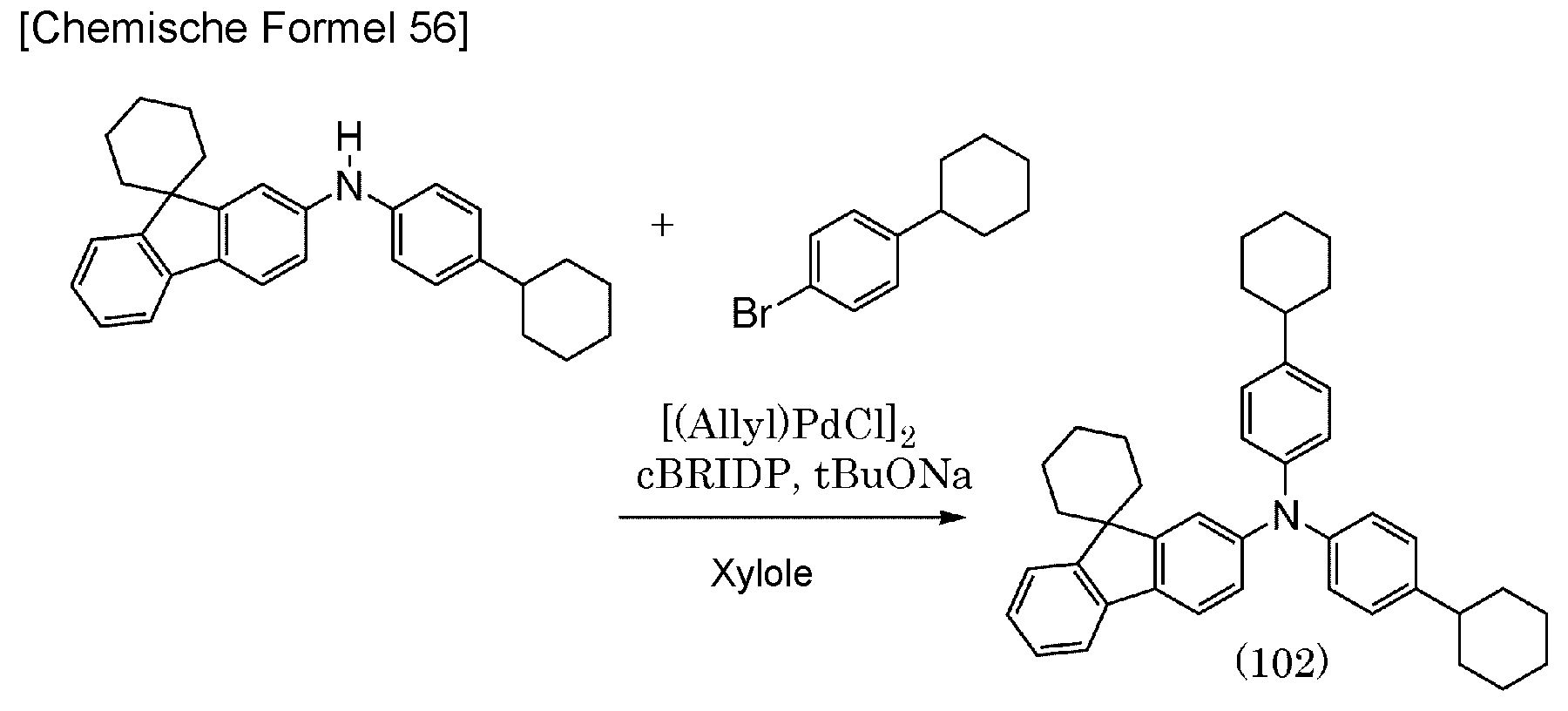
Analyseergebnisse durch Kernspinresonanz- (1H-NMR-) Spektroskopie des im Schritt 3 erhaltenen weißen Feststoffs werden nachstehend gezeigt.
1H-NMR. δ(CDCl3): 7,60-7,65 (m, 2H), 7,54 (d, 1H, J = 8,0 Hz), 7,28-7,35 (m, 2H), 7,19-7,24 (t, 1H, J = 7,5 Hz), 7,02-7,12 (m, 8H), 6,97-7,22 (d, 1H, J = 8,0 Hz), 2,40-2,52 (brm, 2H), 1,79-1,95 (m, 10H), 1,63-1,78 (m, 9H), 1,55-1,63 (m, 1H), 1,32-1,46 (m, 8H), 1,18-1,30 (brm, 2H). 1 H-NMR. δ (CDCl 3 ): 7.60-7.65 (m, 2H), 7.54 (d, 1H, J = 8.0 Hz), 7.28-7.35 (m, 2H), 7, 19-7.24 (t, 1H, J = 7.5 Hz), 7.02-7.12 (m, 8H), 6.97-7.22 (d, 1H, J = 8.0 Hz) , 2.40-2.52 (brm, 2H), 1.79-1.95 (m, 10H), 1.63-1.78 (m, 9H), 1.55-1.63 (m, 1H), 1.32-1.46 (m, 8H), 1.18-1.30 (brm, 2H).
Anschließend wurden 3,1 g des erhaltenen Feststoffs durch ein Train-Sublimationsverfahren gereinigt. Die Sublimationsreinigung wurde durchgeführt, indem eine Erwärmung bei 235 °C unter einem Druck von 3,0 Pa bei der Durchflussrate von Argon von 12,3 ml/min durchgeführt wurde. Nach der Sublimationsreinigung wurden 2,8 g eines blass gelblich-weißen Feststoffs mit einer Sammelquote von 92 % erhalten.Then 3.1 g of the obtained solid was purified by a train sublimation process. The sublimation purification was carried out by performing heating at 235 ° C under a pressure of 3.0 Pa at the flow rate of argon of 12.3 ml / min. After the sublimation purification, 2.8 g of a pale yellowish-white solid with a collection rate of 92% were obtained.
Als Nächstes wurden ein UV-VIS-Absorptionsspektrum (nachstehend einfach als Absorptionsspektrum bezeichnet) von dchPASchF in einer Toluollösung und ein Emissionsspektrum davon gemessen. Das Absorptionsspektrum wurde mit einem UV-VIS-Spektrophotometer (V-550, hergestellt von JASCO Corporation) gemessen, und das Emissionsspektrum wurde mit einem Fluoreszenz-Spektrophotometer (FS920, hergestellt von Hamamatsu Photonics K.K.) gemessen. Die beiden Spektren wurden bei Raumtemperatur gemessen. Eine Quarzzelle wurde für die Messzelle verwendet.
Wie in
Als Nächstes wurde die organische Verbindung dchPASchF einer Massenspektrometrie- (MS-) Analyse durch eine Flüssigchromatographie mit Massenspektrometrie (LC-MS) unterzogen.Next, the organic compound dchPASchF was subjected to mass spectrometry (MS) analysis by liquid chromatography with mass spectrometry (LC-MS).
Bei der LC-MS-Analyse wurde die Flüssigchromatographie- (LC-) Trennung mit ACQUITY UPLC (eingetragenes Markenzeichen), hergestellt von Waters Corporation, durchgeführt, und die Massenspektrometrie- (MS-) Analyse wurde mit Xevo G2 Tof MS, hergestellt von Waters Corporation, durchgeführt. Acquity UPLC BEH C8 (2,1 × 100 mm, 1,7 µm) wurde als Säule für die LC-Trennung verwendet, und die Säulentemperatur war 40 °C. Acetonitril wurde als mobile Phase A verwendet und eine 0,1 % wässrige Lösung von Ameisensäure wurde als mobile Phase B verwendet. Eine Probe wurde ferner auf eine derartige Weise hergestellt, dass dchPASchF in Toluol in einer bestimmten Konzentration aufgelöst wurde und die Mischung mit Acetonitril verdünnt wurde. Die Injektionsmenge betrug 5,0 µl.In LC-MS analysis, liquid chromatography (LC) separation was performed with ACQUITY UPLC (registered trademark) manufactured by Waters Corporation, and mass spectrometry (MS) analysis was performed with Xevo G2 Tof MS manufactured by Waters Corporation. Acquity UPLC BEH C8 (2.1 x 100 mm, 1.7 µm) was used as a column for LC separation, and the column temperature was 40 ° C. Acetonitrile was used as mobile phase A and a 0.1% aqueous solution of formic acid was used as mobile phase B. A sample was further prepared in such a manner that dchPASchF was dissolved in toluene at a certain concentration and the mixture was diluted with acetonitrile. The injection volume was 5.0 µl.
Bei der LC-Trennung war das Verhältnis der mobilen Phase A zu der mobilen Phase B für 10 Minuten nach dem Beginn (0 Minuten) der Messung 95:5.In the LC separation, the ratio of the mobile phase A to the mobile phase B for 10 minutes after the start (0 minutes) of the measurement was 95: 5.
Bei der MS-Analyse wurde eine Ionisation durch ein Elektrosprayionisations- (ESI-) Verfahren durchgeführt. Die Kapillarspannung und die Probenkegel-Spannung wurden dabei auf 3,0 kV bzw. 30 V eingestellt, und eine Erkennung wurde in einem positiven Modus durchgeführt. Eine Komponente mit m/z von 565, die unter den vorstehend beschriebenen Bedingungen ionisiert worden war, wurde in einer Kollisionszelle zur Kollision mit einem Argongas gebracht, so dass sie in Produktionen dissoziierte. Energie (Kollisionsenergie) für die Kollision mit Argon betrug 50 eV. Der Massenbereich für die Messung war auf m/z (Masse-zu-Ladung-Verhältnis) = 100 bis 1500 eingestellt. Die Erkennungsergebnisse der dissoziierten Produktionen mittels Flugzeit- (TOF-) MS werden in
Es sei angemerkt, dass es geschätzt wird, dass sich ein Fragmention bei m/z von 407, das bei der Messung mit einer Kollisionsenergie von 50 eV beobachtet wurde, von N-(4-Cyclohexylphenyl)-N-(spiro[cyclohexan-1,9'[9H]fluoren]-2'yl)amin ableitet, das auf eine derartige Weise erzeugt wurde, dass eine C-N-Bindung von dchPASchF abgeschnitten wurde, und dies ist die Eigenschaften von dchPASchF.Note that it is estimated that a fragment ion at m / z of 407, which was observed when measured with a collision energy of 50 eV, is different from N- (4-cyclohexylphenyl) -N- (spiro [cyclohexane-1 , 9 '[9H] fluorene] -2'yl) amine generated in such a way that a CN bond of dchPASchF was cut, and this is the properties of dchPASchF.
[Beispiel 4][Example 4]
<<Synthesebeispiel 4>><< Synthesis Example 4 >>
In diesem Beispiel wird ein Syntheseverfahren von N-[(4'-Cyclohexyl)-1,1'-biphenyl-4yl]-N-(4-cyclohexylphenyl)-N-(spiro[cyclohexan-1,9'-[9H]fluoren]-2'yl)amin (Abkürzung: chBichPASchF) beschrieben, das die organische Verbindung ist, die durch die Strukturformel (103) der Ausführungsform 1 dargestellt wird. Eine Struktur von chBichPASchF wird nachstehend gezeigt.

<Schritt 1: Synthese von 4-Cyclohexylanilin><Step 1: Synthesis of 4-Cyclohexylaniline>
Die Synthese wurde auf ähnliche Weise wie bei dem Schritt 1 des Synthesebeispiels 3 des Beispiels 3 durchgeführt.Synthesis was carried out in a similar manner to Step 1 of Synthesis Example 3 of Example 3.
<Schritt 2: Synthese von N-(4-Cyclohexylphenyl)-N-(spiro[cyclohexan-1,9'[9H]fluoren]-2'-yl)amin><Step 2: Synthesis of N- (4-Cyclohexylphenyl) -N- (spiro [cyclohexan-1,9 '[9H] fluorene] -2'-yl) amine>
Die Synthese wurde auf ähnliche Weise wie bei dem Schritt 2 des Synthesebeispiels 3 des Beispiels 3 durchgeführt.Synthesis was carried out in a similar manner to Step 2 of Synthesis Example 3 of Example 3.
<Schritt 3: Synthese von N-[(4'-Cyclohexyl)-1,1'-biphenyl-4yl]-N-(4-cyclohexylphenyl)-N-(spiro[cyclohexan-1,9'-[9H]fluoren]-2'yl)amin (Abkürzung: chBichPASchF)><Step 3: Synthesis of N - [(4'-Cyclohexyl) -1,1'-biphenyl-4yl] -N- (4-cyclohexylphenyl) -N- (spiro [cyclohexane-1,9 '- [9H] fluorene) ] -2'yl) amine (abbreviation: chBichPASchF)>
In einen Dreihalskolben wurden 2,5 g (6,2 mmol) N-(4-Cyclohexylphenyl)-N-(spiro[cyclohexan-1,9'[9H]fluoren]-2'-yl)amin, das im Schritt 2 erhalten worden war, 1,7 g (6,2 mmol) 4'-Cyclohexyl-4-chlor-1,1'-biphenyl, 1,8 g (18,6 mmol) Natrium-tert-butoxid und 31 ml Xylol gegeben. Diese Mischung wurde unter reduziertem Druck entgast, und dann wurde die Luft in dem Kolben durch Stickstoff ersetzt. Die Mischung wurde gerührt, während sie auf 50 °C erwärmt wurde. Anschließend wurden 23 mg (0,062 mmol) Allylpalladium(II)chloriddimer (Abkürzung: [(Allyl)PdCl]2) und 88 mg (0,248 mmol) Di-tert-butyl(1-methyl-2,2-diphenylcyclopropyl)phosphin (Abkürzung: cBRIDP (eingetragenes Markenzeichen)) hinzugefügt, und die Mischung wurde ungefähr 5 Stunden lang bei 110 °C erwärmt. Danach wurde die Temperatur des Kolbens auf etwa 60 °C verringert, der Mischung wurde ungefähr 1 ml Wasser hinzugefügt, und ein ausgefällter Feststoff wurde durch Filtration abgetrennt. Das Filtrat wurde konzentriert, und die erhaltene Lösung wurde durch Kieselgel-Säulenchromatographie gereinigt. Die erhaltene Lösung wurde konzentriert, um eine kondensierte Toluollösung zu erhalten. Dieser Toluollösung wurde Ethanol hinzugefügt, und die Toluollösung wurde unter reduziertem Druck konzentriert, wodurch eine Ethanol-Suspension erhalten wurde. Das Präzipitat wurde bei 20 °C gefiltert und der erhaltene Feststoff wurde bei etwa 80 °C unter reduziertem Druck getrocknet, wodurch 2,7 g eines weißen Zielfeststoffs in einer Ausbeute von 68 % erhalten wurden. Das Syntheseschema des Schritts 3 wird nachstehend gezeigt.

Analyseergebnisse durch Kernspinresonanz- (1H-NMR-) Spektroskopie des im Schritt 3 erhaltenen weißen Feststoffs werden nachstehend gezeigt.
1H-NMR. δ(CDCl3) : 7,65 (d, 2H, J = 8,0 Hz), 7,58 (d, 1H, J = 8,0 Hz), 7,51 (d, 2H, J = 8,5 Hz), 7,46 (m, 2H), 7,39 (d, 1H, 1,5 Hz), 7,32 (t, 1H, J = 8,0 Hz), 7,21-7,38 (m, 3H), 7,14-7,18 (m, 2H), 7,08-7,14 (m, 4H), 7,06 (dd, 1H, J = 8,0 Hz, 1,5 Hz), 2,43-2,57 (brm, 2H), 1,80-1,97 (m, 10H), 1,64-1,80 (m, 9H), 1,56-1,64 (m, 1H), 1,34-1,53 (m, 8H), 1,20-1,32 (brm, 2H). 1 H-NMR. δ (CDCl 3 ): 7.65 (d, 2H, J = 8.0 Hz), 7.58 (d, 1H, J = 8.0 Hz), 7.51 (d, 2H, J = 8, 5 Hz), 7.46 (m, 2H), 7.39 (d, 1H, 1.5 Hz), 7.32 (t, 1H, J = 8.0 Hz), 7.21-7.38 (m, 3H), 7.14-7.18 (m, 2H), 7.08-7.14 (m, 4H), 7.06 (dd, 1H, J = 8.0 Hz, 1.5 Hz), 2.43-2.57 (brm, 2H), 1.80-1.97 (m, 10H), 1.64 -1.80 (m, 9H), 1.56-1.64 (m, 1H), 1.34-1.53 (m, 8H), 1.20-1.32 (brm, 2H).
Anschließend wurden 2,6 g des erhaltenen Feststoffs durch ein Train-Sublimationsverfahren gereinigt. Die Sublimationsreinigung wurde durchgeführt, indem eine Erwärmung bei 275 °C unter einem Druck von 3,0 Pa bei der Durchflussrate von Argon von 12,3 ml/min durchgeführt wurde. Nach der Sublimationsreinigung wurden 2,3 g eines blass gelblich-weißen Feststoffs mit einer Sammelquote von 89 % erhalten.Then 2.6 g of the obtained solid was purified by a train sublimation process. The sublimation purification was carried out by performing heating at 275 ° C. under a pressure of 3.0 Pa at the flow rate of argon of 12.3 ml / min. After the sublimation purification, 2.3 g of a pale yellowish-white solid with a collection rate of 89% were obtained.
Als Nächstes wurden ein UV-VIS-Absorptionsspektrum (nachstehend einfach als Absorptionsspektrum bezeichnet) von chBichPASchF in einer Toluollösung und ein Emissionsspektrum davon gemessen. Das Absorptionsspektrum wurde mit einem UV-VIS-Spektrophotometer (V-550, hergestellt von JASCO Corporation) gemessen, und das Emissionsspektrum wurde mit einem Fluoreszenz-Spektrophotometer (FS920, hergestellt von Hamamatsu Photonics K.K.) gemessen. Die beiden Spektren wurden bei Raumtemperatur gemessen. Eine Quarzzelle wurde für die Messzelle verwendet.
Wie in
Als Nächstes wurde die organische Verbindung chBichPASchF einer Massenspektrometrie- (MS-) Analyse durch eine Flüssigchromatographie mit Massenspektrometrie (LC-MS) unterzogen.Next, the organic compound chBichPASchF was subjected to mass spectrometry (MS) analysis by liquid chromatography with mass spectrometry (LC-MS).
Bei der LC-MS-Analyse wurde die Flüssigchromatographie- (LC-) Trennung mit ACQUITY UPLC (eingetragenes Markenzeichen), hergestellt von Waters Corporation, durchgeführt, und die Massenspektrometrie- (MS-) Analyse wurde mit Xevo G2 Tof MS, hergestellt von Waters Corporation, durchgeführt. Acquity UPLC BEH C8 (2,1 × 100 mm, 1,7 µm) wurde als Säule für die LC-Trennung verwendet, und die Säulentemperatur war 40 °C. Acetonitril wurde als mobile Phase A verwendet und eine 0,1 % wässrige Lösung von Ameisensäure wurde als mobile Phase B verwendet. Eine Probe wurde ferner auf eine derartige Weise hergestellt, dass chBichPASchF in Toluol in einer bestimmten Konzentration aufgelöst wurde und die Mischung mit Acetonitril verdünnt wurde. Die Injektionsmenge betrug 5,0 µl.In LC-MS analysis, liquid chromatography (LC) separation was performed with ACQUITY UPLC (registered trademark) manufactured by Waters Corporation, and mass spectrometry (MS) analysis was performed with Xevo G2 Tof MS manufactured by Waters Corporation. Acquity UPLC BEH C8 (2.1 x 100 mm, 1.7 µm) was used as a column for LC separation, and the column temperature was 40 ° C. Acetonitrile was used as mobile phase A and a 0.1% aqueous solution of formic acid was used as mobile phase B. A sample was further prepared in such a manner that chBichPASchF was dissolved in toluene at a certain concentration and the mixture was diluted with acetonitrile. The injection volume was 5.0 µl.
Bei der LC-Trennung war das Verhältnis der mobilen Phase A zu der mobilen Phase B für 10 Minuten nach dem Beginn (0 Minuten) der Messung 95:5.In the LC separation, the ratio of the mobile phase A to the mobile phase B for 10 minutes after the start (0 minutes) of the measurement was 95: 5.
Bei der MS-Analyse wurde eine Ionisation durch ein Elektrosprayionisations- (ESI-) Verfahren durchgeführt. Die Kapillarspannung und die Probenkegel-Spannung wurden dabei auf 3,0 kV bzw. 30 V eingestellt, und eine Erkennung wurde in einem positiven Modus durchgeführt. Eine Komponente mit m/z von 641, die unter den vorstehend beschriebenen Bedingungen ionisiert worden war, wurde in einer Kollisionszelle zur Kollision mit einem Argongas gebracht, so dass sie in Produktionen dissoziierte. Energie (Kollisionsenergie) für die Kollision mit Argon betrug 60 eV. Der Massenbereich für die Messung war auf m/z (Masse-zu-Ladung-Verhältnis) = 100 bis 1500 eingestellt. Die Erkennungsergebnisse der dissoziierten Produktionen mittels Flugzeit- (TOF-) MS werden in
Es sei angemerkt, dass es geschätzt wird, dass sich ein Fragmention bei m/z von 482, das bei der Messung mit einer Kollisionsenergie von 60 eV beobachtet wurde, von N-[(4'-Cyclohexyl)-1,1'-biphenyl-4-yl]-N-(spiro[cyclohexan-1,9'-[9H]-fluoren]-2'-yl)-amin ableitet, das auf eine derartige Weise erzeugt wurde, dass eine C-N-Bindung von chBichPASchF abgeschnitten wurde, und dies ist die Eigenschaften von chBichPASchF.Note that it is estimated that a fragment ion at m / z of 482, which was observed when measured with a collision energy of 60 eV, is different from N - [(4'-cyclohexyl) -1,1'-biphenyl -4-yl] -N- (spiro [cyclohexane-1,9 '- [9H] -fluoren] -2'-yl) -amine, which was generated in such a way that a CN bond of chBichPASchF was cut was, and this is the characteristics of chBichPASchF.
Als Nächstes wurde Tg von chBichPASchF gemessen. Tg wurde unter Verwendung eines dynamischen Differenzkalorimeters (Perkin-Elmer Co., Ltd. Pyris 1 DSC) in einem Zustand, in dem ein Pulver auf eine Aluminiumzelle gegeben wurde, gemessen. Als Ergebnis war Tg von chBichPASchF 102 °C.Next, the Tg of chBichPASchF was measured. Tg was measured using a differential dynamic calorimeter (Perkin-Elmer Co., Ltd.
[Beispiel 5][Example 5]
<<Synthesebeispiel>><<Synthesis example>>
In diesem Beispiel wird ein Syntheseverfahren von N-(4-Cyclohexylphenyl)-bis(spiro[cyclohexan-1,9'-[9H]fluoren]-2'-yl)amin (Abkürzung: SchFB1chP) beschrieben, das die organische Verbindung ist, die durch die Strukturformel (104) der Ausführungsform 1 dargestellt wird. Eine Struktur von SchFB1chP wird nachstehend gezeigt.

<Schritt 1: Synthese von 4-Cyclohexylanilin><Step 1: Synthesis of 4-Cyclohexylaniline>
Die Synthese wurde auf ähnliche Weise wie bei dem Schritt 1 des Synthesebeispiels 3 des Beispiels 3 durchgeführt.Synthesis was carried out in a similar manner to Step 1 of Synthesis Example 3 of Example 3.
<Schritt 2: Synthese von N-(4-Cyclohexylphenyl)-N-(spiro[cyclohexan-1,9'[9H]fluoren]-2'-yl)amin><Step 2: Synthesis of N- (4-Cyclohexylphenyl) -N- (spiro [cyclohexan-1,9 '[9H] fluorene] -2'-yl) amine>
Die Synthese wurde auf ähnliche Weise wie bei dem Schritt 2 des Synthesebeispiels 3 des Beispiels 3 durchgeführt.Synthesis was carried out in a similar manner to Step 2 of Synthesis Example 3 of Example 3.
<Schritt 3: Synthese von N-(4-Cyclohexylphenyl)-bis(spiro[cyclohexan-1,9'-[9H]fluoren]-2'-yl)amin (Abkürzung: SchFB1chP)><Step 3: Synthesis of N- (4-Cyclohexylphenyl) bis (spiro [cyclohexane-1,9 '- [9H] fluorene] -2'-yl) amine (Abbreviation: SchFB1chP)>
In einen Dreihalskolben wurden 3,0 g (16,9 mmol) 4-Cyclohexylanilin, dessen Syntheseverfahren im Schritt 2 beschrieben worden war, 5,3 g (16,9 mmol) 2'-Brom(spiro[cyclohexan-1,9'[9H]fluoren]), 4,9 g (50,7 mmol) Natrium-tert-butoxid und 85 ml Xylol gegeben. Diese Mischung wurde unter reduziertem Druck entgast, und dann wurde die Luft in dem Kolben durch Stickstoff ersetzt. Die Mischung wurde gerührt, während sie auf 60 °C erwärmt wurde. Anschließend wurden 62 mg (0,17 mmol) Allylpalladium(II)chloriddimer (Abkürzung: [(Allyl)PdCl]2) und 280 mg (0,67 mmol) Di-tert-butyl(1-methyl-2,2-diphenylcyclopropyl)phosphin (Abkürzung: cBRIDP (eingetragenes Markenzeichen)) hinzugefügt. Diese Mischung wurde bei 90 °C erwärmt und ungefähr 7 Stunden lang reagiert. Danach wurde die Temperatur des Kolbens auf etwa 60 °C verringert, der Mischung wurde ungefähr 1 ml Wasser hinzugefügt, und ein ausgefällter Feststoff wurde durch Filtration abgetrennt. Das Filtrat wurde konzentriert, und die erhaltene Lösung wurde durch Kieselgel-Säulenchromatographie gereinigt. Die erhaltene Lösung wurde konzentriert, um eine kondensierte Toluollösung zu erhalten. Dieser Toluollösung wurde Ethanol hinzugefügt, und die Toluollösung wurde unter reduziertem Druck konzentriert, wodurch eine Ethanol-Suspension erhalten wurde. Das Präzipitat wurde bei 20 °C gefiltert und der erhaltene Feststoff wurde bei etwa 80 °C unter reduziertem Druck getrocknet, wodurch 0,95 g eines weißen Zielfeststoffs in einer Ausbeute von 8,8 % erhalten wurden. Das Syntheseschema des Schritts 3 wird nachstehend gezeigt.


Analyseergebnisse durch Kernspinresonanz- (1H-NMR-) Spektroskopie des im Schritt 3 erhaltenen weißen Feststoffs werden nachstehend gezeigt.
1H-NMR. δ(CDCl3) : 7,64 (t, 4H, J = 8,0 Hz), 7,59 (d, 2H, J = 8,5 Hz), 7,39 (brs, 2H), 7,33 (t, 2H, J = 7,5 Hz), 7,20-7,25 (m, 2H), 7,12 (brs, 4H), 7,08 (d, 2H, J = 8,0 Hz), 2,44-2,52 (brm, 1H), 1,63-1,97 (m, 23H), 1,50-1,61 (m, 2H), 1,34-1,48 (m, 4H), 1,20-1,32 (brm, 1H). 1 H-NMR. δ (CDCl 3 ): 7.64 (t, 4H, J = 8.0 Hz), 7.59 (d, 2H, J = 8.5 Hz), 7.39 (brs, 2H), 7.33 (t, 2H, J = 7.5 Hz), 7.20-7.25 (m, 2H), 7.12 (brs, 4H), 7.08 (d, 2H, J = 8.0 Hz) , 2.44-2.52 (brm, 1H), 1.63-1.97 (m, 23H), 1.50-1.61 (m, 2H), 1.34-1.48 (m, 4H), 1.20-1.32 (brm, 1H).
Anschließend wurden 0,93 g des erhaltenen Feststoffs durch ein Train-Sublimationsverfahren gereinigt. Die Sublimationsreinigung wurde durchgeführt, indem eine Erwärmung bei 250 °C unter einem Druck von 3,0 Pa bei der Durchflussrate von Argon von 13,3 ml/min durchgeführt wurde. Nach der Sublimationsreinigung wurden 0,64 g eines blass gelblich-weißen Feststoffs mit einer Sammelquote von 69 % erhalten.Then 0.93 g of the solid obtained was purified by a train sublimation method. The sublimation purification was carried out by performing heating at 250 ° C. under a pressure of 3.0 Pa at the flow rate of argon of 13.3 ml / min. After the sublimation purification, 0.64 g of a pale yellowish-white solid was obtained with a collection rate of 69%.
Als Nächstes wurden ein UV-VIS-Absorptionsspektrum (nachstehend einfach als Absorptionsspektrum bezeichnet) von SchFB1chP in einer Toluollösung und ein Emissionsspektrum davon gemessen. Das Absorptionsspektrum wurde mit einem UV-VIS-Spektrophotometer (V-550, hergestellt von JASCO Corporation) gemessen, und das Emissionsspektrum wurde mit einem Fluoreszenz-Spektrophotometer (FS920, hergestellt von Hamamatsu Photonics K.K.) gemessen. Die beiden Spektren wurden bei Raumtemperatur gemessen. Eine Quarzzelle wurde für die Messzelle verwendet.
Wie in
Als Nächstes wurde die organische Verbindung SchFB1chP einer Massenspektrometrie- (MS-) Analyse durch eine Flüssigchromatographie mit Massenspektrometrie (LC-MS) unterzogen.Next, the organic compound SchFB1chP was subjected to mass spectrometry (MS) analysis by liquid chromatography with mass spectrometry (LC-MS).
Bei der LC-MS-Analyse wurde die Flüssigchromatographie- (LC-) Trennung mit ACQUITY UPLC (eingetragenes Markenzeichen), hergestellt von Waters Corporation, durchgeführt, und die Massenspektrometrie- (MS-) Analyse wurde mit Xevo G2 Tof MS, hergestellt von Waters Corporation, durchgeführt. Acquity UPLC BEH C8 (2,1 × 100 mm, 1,7 µm) wurde als Säule für die LC-Trennung verwendet, und die Säulentemperatur war 40 °C. Acetonitril wurde als mobile Phase A verwendet und eine 0,1 % wässrige Lösung von Ameisensäure wurde als mobile Phase B verwendet. Eine Probe wurde ferner auf eine derartige Weise hergestellt, dass SchFB1chP in Toluol in einer bestimmten Konzentration aufgelöst wurde und die Mischung mit Acetonitril verdünnt wurde. Die Injektionsmenge betrug 5,0 µl.In LC-MS analysis, liquid chromatography (LC) separation was performed with ACQUITY UPLC (registered trademark) manufactured by Waters Corporation, and mass spectrometry (MS) analysis was performed with Xevo G2 Tof MS manufactured by Waters Corporation. Acquity UPLC BEH C8 (2.1 x 100 mm, 1.7 µm) was used as a column for LC separation, and the column temperature was 40 ° C. Acetonitrile was used as mobile phase A and a 0.1% aqueous solution of formic acid was used as mobile phase B. A sample was further prepared in such a manner that SchFB1chP was dissolved in toluene at a certain concentration and the mixture was diluted with acetonitrile. The injection volume was 5.0 µl.
Bei der LC-Trennung war das Verhältnis der mobilen Phase A zu der mobilen Phase B für 10 Minuten nach dem Beginn (0 Minuten) der Messung 95:5.In the LC separation, the ratio of the mobile phase A to the mobile phase B for 10 minutes after the start (0 minutes) of the measurement was 95: 5.
Bei der MS-Analyse wurde eine Ionisation durch ein Elektrosprayionisations- (ESI-) Verfahren durchgeführt. Die Kapillarspannung und die Probenkegel-Spannung wurden dabei auf 3,0 kV bzw. 30 V eingestellt, und eine Erkennung wurde in einem positiven Modus durchgeführt. Eine Komponente mit m/z von 639, die unter den vorstehend beschriebenen Bedingungen ionisiert worden war, wurde in einer Kollisionszelle zur Kollision mit einem Argongas gebracht, so dass sie in Produktionen dissoziierte. Energie (Kollisionsenergie) für die Kollision mit Argon betrug 60 eV. Der Massenbereich für die Messung war auf m/z (Masse-zu-Ladung-Verhältnis) = 100 bis 1500 eingestellt. Die Erkennungsergebnisse der dissoziierten Produktionen mittels Flugzeit- (TOF-) MS werden in
Es sei angemerkt, dass es geschätzt wird, dass sich ein Fragmention bei m/z von 481, das bei der Messung mit einer Kollisionsenergie von 60 eV beobachtet wurde, von N,N-Bis(spiro[cyclohexan-1,9'-[9H]fluoren]-2'-yl)amin ableitet, das auf eine derartige Weise erzeugt wurde, dass eine C-N-Bindung von SchFB1chP abgeschnitten wurde, und dies ist die Eigenschaften von SchFB1chP.Note that it is estimated that a fragment ion at m / z of 481, which was observed when measured with a collision energy of 60 eV, is from N, N-bis (spiro [cyclohexane-1,9 '- [ 9H] fluorene] -2'-yl) amine generated in such a manner that a C [BOND] N bond of SchFB1chP was cut, and this is the property of SchFB1chP.
Als Nächstes wurde Tg von SchFB1chP gemessen. Tg wurde unter Verwendung eines dynamischen Differenzkalorimeters (Perkin-Elmer Co., Ltd. Pyris 1 DSC) in einem Zustand, in dem ein Pulver auf eine Aluminiumzelle gegeben wurde, gemessen. Als Ergebnis war Tg von SchFB1chP 112 °C.Next, the Tg of SchFB1chP was measured. Tg was measured using a differential dynamic calorimeter (Perkin-Elmer Co., Ltd.
[Beispiel 6][Example 6]
<<Synthesebeispiel 6>><< Synthesis Example 6 >>
In diesem Beispiel wird ein Syntheseverfahren von N-[(3',5'-Ditertiarybutyl)-1,1'-biphenyl-4-yl]-N-(4-cyclohexylphenyl)-9,9-dimethyl-9H-fluoren-2-amin (Abkürzung: mmtBuBichPAF) beschrieben, das die organische Verbindung ist, die durch die Strukturformel (105) der Ausführungsform 1 dargestellt wird. Eine Struktur von mmtBuBichPAF wird nachstehend gezeigt.


<Schritt 1: Synthese von 3',5'-Ditertiarybutyl-4-chlor-1,1'-biphenyl><Step 1: Synthesis of 3 ', 5'-Ditertiarybutyl-4-chloro-1,1'-biphenyl>
In einen Dreihalskolben wurden 13,5 g (50 mmol) 3,5-Ditertiarybutyl-1-brombenzol, 8,2 g (52,5 mmol) 4-Chlorphenylboronsäure, 21,8 g (158 mmol) Kaliumcarbonat, 125 ml Toluol, 31 ml Ethanol und 40 ml Wasser gegeben. Diese Mischung wurde unter reduziertem Druck entgast, und dann wurde die Luft in dem Kolben durch Stickstoff ersetzt. Dieser Mischung wurden 225 mg (1,0 mmol) Palladiumacetat und 680 mg (2,0 mmol) Tris(2,6-methylphenyl)phosphin hinzugefügt, und die Mischung wurde ungefähr 3 Stunden lang bei 80 °C erwärmt und refluxiert. Danach wurde die Temperatur des Kolbens auf Raumtemperatur verringert, und die Mischung wurde in eine organische Schicht und eine wässrige Schicht getrennt. Dieser Lösung wurde Magnesiumsulfat für die Trocknung hinzugefügt, um konzentriert zu werden. Die erhaltene Lösung wurde durch Kieselgel-Säulenchromatographie gereinigt. Die erhaltene Lösung wurde konzentriert und zum Aushärten getrocknet. Danach wurde Hexan für eine Umkristallisation hinzugefügt. Die Mischlösung, in der ein weißer Feststoff ausgefällt wurde, wurde mit Eis gekühlt und gefiltert. Der erhaltene Feststoff wurde bei etwa 60 °C in einem Vakuum getrocknet, wodurch 9,5 g eines weißen Zielfeststoffs in einer Ausbeute von 63 % erhalten wurden. Das Syntheseschema des Schritts 1 wird nachstehend gezeigt.


<Schritt 2: Synthese von N-(4-Cycrohexylphenyl)-N-(9,9-dimethyl-9H-fluoren-2yl)amin><Step 2: Synthesis of N- (4-Cycrohexylphenyl) -N- (9,9-dimethyl-9H-fluoren-2yl) amine>
Die Synthese wurde auf ähnliche Weise wie bei dem Schritt 1 des Synthesebeispiels 2 des Beispiels 2 durchgeführt.Synthesis was carried out in a similar manner to Step 1 of Synthesis Example 2 of Example 2.
<Schritt 3: Synthese von N-[(3',5'-Ditertiarybutyl)-1,1'-biphenyl-4-yl]-N-(4-cyclohexylphenyl)-9,9-dimethyl-9H-fluoren-2-amin (Abkürzung: mmtBuBichPAF)><Step 3: Synthesis of N - [(3 ', 5'-Ditertiarybutyl) -1,1'-biphenyl-4-yl] -N- (4-cyclohexylphenyl) -9,9-dimethyl-9H-fluorene-2 -amin (abbreviation: mmtBuBichPAF)>
In einen Dreihalskolben wurden 3,2 g (10,6 mmol) 3',5'-Ditertiarybutyl-4-chlor-1,1'-biphenyl, das im Schritt 1 erhalten worden war, 3,9 g (10,6 mmol) N-(4-Cycrohexylphenyl)-N-(9,9-dimethyl-9H-fluoren-2yl)amin, das im Schritt 2 erhalten worden war, 3,1 g (31,8 mmol) Natrium-tert-butoxid und 53 ml Xylol gegeben. Diese Mischung wurde unter reduziertem Druck entgast, und dann wurde die Luft in dem Kolben durch Stickstoff ersetzt. Die Mischung wurde gerührt, während sie auf 50 °C erwärmt wurde. Anschließend wurden 39 mg (0,11 mmol) Allylpalladium(II)chloriddimer (Abkürzung: [(Allyl)PdCl]2) und 150 mg (0,42 mmol) Di-tert-butyl(1 -methyl-2,2-diphenylcyclopropyl)phosphin (Abkürzung: cBRIDP (eingetragenes Markenzeichen)) hinzugefügt, und diese Mischung wurde ungefähr 3 Stunden lang bei120 °C erwärmt. Danach wurde die Temperatur des Kolbens auf etwa 60 °C verringert, der Mischung wurde ungefähr 1 ml Wasser hinzugefügt, und ein ausgefällter Feststoff wurde durch Filtration abgetrennt. Das Filtrat wurde konzentriert, und die erhaltene Lösung wurde durch Kieselgel-Säulenchromatographie gereinigt. Die erhaltene Lösung wurde konzentriert, um eine kondensierte Toluollösung zu erhalten. Dieser Toluollösung wurde Ethanol hinzugefügt, und die Toluollösung wurde unter reduziertem Druck konzentriert, wodurch eine Ethanol-Suspension erhalten wurde. Das Präzipitat wurde bei 20 °C gefiltert und der erhaltene Feststoff wurde bei etwa 80 °C unter reduziertem Druck getrocknet, wodurch 5,8 g eines weißen Zielfeststoffs in einer Ausbeute von 87 % erhalten wurden. Das Syntheseschema des Schritts 3 wird nachstehend gezeigt.

Analyseergebnisse durch Kernspinresonanz- (1H-NMR-) Spektroskopie des im Schritt 3 erhaltenen weißen Feststoffs werden nachstehend gezeigt.
1H-NMR. δ(CDCl3) : 7,63 (d, 1H, J = 7,5 Hz), 7,57 (d, 1H, J = 8,0 Hz), 7,44-7,49 (m, 2H), 7,37-7,42 (m, 4H), 7,31 (td, 1H, J = 7,5 Hz, 2,0 Hz), 7,23-7,27 (m, 2H), 7,15-7,19 (m, 2H), 7,08-7,14 (m, 4H), 7,05 (dd, 1H, J = 8,0 Hz, 2,0 Hz), 2,43-2,53 (brm, 1H), 1,81-1,96 (m, 4H), 1,75 (d, 1H, J = 12,5 Hz), 1,32-1,48 (m, 28H), 1,20-1,31 (brm, 1H). 1 H-NMR. δ (CDCl 3 ): 7.63 (d, 1H, J = 7.5 Hz), 7.57 (d, 1H, J = 8.0 Hz), 7.44-7.49 (m, 2H) , 7.37-7.42 (m, 4H), 7.31 (td, 1H, J = 7.5 Hz, 2.0 Hz), 7.23-7.27 (m, 2H), 7, 15-7.19 (m, 2H), 7.08-7.14 (m, 4H), 7.05 (dd, 1H, J = 8.0 Hz, 2.0 Hz), 2.43-2 .53 (brm, 1H), 1.81-1.96 (m, 4H), 1.75 (d, 1H, J = 12.5 Hz), 1.32-1.48 (m, 28H), 1.20-1.31 (brm, 1H).
Anschließend wurden 3,5 g des erhaltenen Feststoffs durch ein Train-Sublimationsverfahren gereinigt. Die Sublimationsreinigung wurde durchgeführt, indem eine Erwärmung bei 255 °C unter einem Druck von 3,0 Pa bei der Durchflussrate von Argon von 11,8 ml/min durchgeführt wurde. Nach der Sublimationsreinigung wurden 3,1 g eines blass gelblich-weißen Feststoffs mit einer Sammelquote von 89 % erhalten.Subsequently, 3.5 g of the solid obtained was purified by a train sublimation method. The sublimation purification was carried out by performing heating at 255 ° C. under a pressure of 3.0 Pa at the flow rate of argon of 11.8 ml / min. After the sublimation purification, 3.1 g of a pale yellowish-white solid with a collection rate of 89% were obtained.
Als Nächstes wurden ein UV-VIS-Absorptionsspektrum (nachstehend einfach als Absorptionsspektrum bezeichnet) von mmtBuBichPAF in einer Toluollösung und ein Emissionsspektrum davon gemessen. Das Absorptionsspektrum wurde mit einem UV-VIS-Spektrophotometer (V-550, hergestellt von JASCO Corporation) gemessen, und das Emissionsspektrum wurde mit einem Fluoreszenz-Spektrophotometer (FS920, hergestellt von Hamamatsu Photonics K.K.) gemessen. Die beiden Spektren wurden bei Raumtemperatur gemessen. Eine Quarzzelle wurde für die Messzelle verwendet.
Wie in
Als Nächstes wurde die organische Verbindung mmtBuBichPAF einer Massenspektrometrie- (MS-) Analyse durch eine Flüssigchromatographie mit Massenspektrometrie (LC-MS) unterzogen.Next, the organic compound mmtBuBichPAF was subjected to mass spectrometry (MS) analysis by liquid chromatography with mass spectrometry (LC-MS).
Bei der LC-MS-Analyse wurde die Flüssigchromatographie- (LC-) Trennung mit ACQUITY UPLC (eingetragenes Markenzeichen), hergestellt von Waters Corporation, durchgeführt, und die Massenspektrometrie- (MS-) Analyse wurde mit Xevo G2 Tof MS, hergestellt von Waters Corporation, durchgeführt. Acquity UPLC BEH C8 (2,1 × 100 mm, 1,7 µm) wurde als Säule für die LC-Trennung verwendet, und die Säulentemperatur war 40 °C. Acetonitril wurde als mobile Phase A verwendet und eine 0,1 % wässrige Lösung von Ameisensäure wurde als mobile Phase B verwendet. Eine Probe wurde ferner auf eine derartige Weise hergestellt, dass mmtBuBichPAF in Toluol in einer bestimmten Konzentration aufgelöst wurde und die Mischung mit Acetonitril verdünnt wurde. Die Injektionsmenge betrug 5,0 µl.In LC-MS analysis, liquid chromatography (LC) separation was performed with ACQUITY UPLC (registered trademark) manufactured by Waters Corporation, and mass spectrometry (MS) analysis was performed with Xevo G2 Tof MS manufactured by Waters Corporation. Acquity UPLC BEH C8 (2.1 x 100 mm, 1.7 µm) was used as a column for LC separation, and the column temperature was 40 ° C. Acetonitrile was used as mobile phase A and a 0.1% aqueous solution of formic acid was used as mobile phase B. A sample was further prepared in such a manner that mmtBuBichPAF was dissolved in toluene at a certain concentration and the mixture was diluted with acetonitrile. The injection volume was 5.0 µl.
Bei der LC-Trennung war das Verhältnis der mobilen Phase A zu der mobilen Phase B für 10 Minuten nach dem Beginn (0 Minuten) der Messung 95:5.In the LC separation, the ratio of the mobile phase A to the mobile phase B for 10 minutes after the start (0 minutes) of the measurement was 95: 5.
Bei der MS-Analyse wurde eine Ionisation durch ein Elektrosprayionisations- (ESI-) Verfahren durchgeführt. Die Kapillarspannung und die Probenkegel-Spannung wurden dabei auf 3,0 kV bzw. 30 V eingestellt, und eine Erkennung wurde in einem positiven Modus durchgeführt. Eine Komponente mit m/z von 631, die unter den vorstehend beschriebenen Bedingungen ionisiert worden war, wurde in einer Kollisionszelle zur Kollision mit einem Argongas gebracht, so dass sie in Produktionen dissoziierte. Energie (Kollisionsenergie) für die Kollision mit Argon betrug 60 eV. Der Massenbereich für die Messung war auf m/z (Masse-zu-Ladung-Verhältnis) = 100 bis 1500 eingestellt. Die Erkennungsergebnisse der dissoziierten Produktionen mittels Flugzeit- (TOF-) MS werden in
Es sei angemerkt, dass es geschätzt wird, dass sich ein Fragmention bei m/z von 473, das bei der Messung mit einer Kollisionsenergie von 60 eV beobachtet wurde, von N-(3',5'-Ditertiarybutyl-1,1'-biphenyl-4-yl)-N-(9,9-dimethyl-9H-fluoren-2yl)amin ableitet, das auf eine derartige Weise erzeugt wurde, dass eine C-N-Bindung von mmtBuBichPAF abgeschnitten wurde, und dies ist die Eigenschaften von mmtBuBichPAF.Note that it is estimated that a fragment ion at m / z of 473, which was observed when measured with a collision energy of 60 eV, is from N- (3 ', 5'-di-tertiarybutyl-1,1'- biphenyl-4-yl) -N- (9,9-dimethyl-9H-fluoren-2yl) amine, which was generated in such a way that a CN bond was cut from mmtBuBichPAF, and this is the property of mmtBuBichPAF .
Als Nächstes wurde Tg von mmtBuBichPAF gemessen. Tg wurde unter Verwendung eines dynamischen Differenzkalorimeters (Perkin-Elmer Co., Ltd. Pyris 1 DSC) in einem Zustand, in dem ein Pulver auf eine Aluminiumzelle gegeben wurde, gemessen. Als Ergebnis war Tg von mmtBuBichPAF 102 °C.Next, the Tg of mmtBuBichPAF was measured. Tg was measured using a differential dynamic calorimeter (Perkin-Elmer Co., Ltd.
[Beispiel 7][Example 7]
<<Synthesebeispiel 7>><< Synthesis Example 7 >>
In diesem Beispiel wird ein Syntheseverfahren von N,N-Bis(3',5'-ditertiarybutyl-1,1'-biphenyl-4-yl)-9,9,-dimethyl-9H-fluoren-2-amin (Abkürzung: dmmtBuBiAF) beschrieben, das die organische Verbindung ist, die durch die Strukturformel (106) der Ausführungsform 1 dargestellt wird. Eine Struktur von dmmtBuBiAF wird nachstehend gezeigt.

<Schritt 1: Synthese von 3',5'-Ditertiarybutyl-4-chlor-1,1'-biphenyl><Step 1: Synthesis of 3 ', 5'-Ditertiarybutyl-4-chloro-1,1'-biphenyl>
Die Synthese wurde auf ähnliche Weise wie bei dem Schritt 1 des Synthesebeispiels 6 des Beispiels 6 durchgeführt.Synthesis was carried out in a similar manner to Step 1 of Synthesis Example 6 of Example 6.
<Schritt 2: Synthese von N,N-Bis(3',5'-ditertiarybutyl-1,1'-biphenyl-4-yl)-9,9,-dimethyl-9H-fluoren-2-amin (Abkürzung: dmmtBuBiAF)><Step 2: Synthesis of N, N-bis (3 ', 5'-ditertiarybutyl-1,1'-biphenyl-4-yl) -9,9, -dimethyl-9H-fluorene-2-amine (abbreviation: dmmtBuBiAF )>
In einen Dreihalskolben wurden 2,8 g (13,5 mmol) 9,9-Dimethyl-9H-fluoren-2-amin, 6,1 g (20,3 mmol) 3',5'-Ditertiarybutyl-4-chlor-1,1'-biphenyl, das im Schritt 1 erhalten worden war, 5,8 g (60,8 mmol) Natrium-tert-butoxid und 70 ml Xylol gegeben. Diese Mischung wurde unter reduziertem Druck entgast, und dann wurde die Luft in dem Kolben durch Stickstoff ersetzt. Die Mischung wurde gerührt, während sie auf 50 °C erwärmt wurde. Anschließend wurden 100 mg (0,27 mmol) Allylpalladium(II)chloriddimer (Abkürzung: [(Allyl)PdCl]2) und 381 mg (1,08 mmol) Di-tert-butyl(1 -methyl-2,2-diphenylcyclopropyl)phosphin (Abkürzung: cBRIDP (eingetragenes Markenzeichen)) hinzugefügt, und die Mischung wurde ungefähr 3 Stunden lang bei 120 °C erwärmt. Danach wurde die Temperatur des Kolbens auf etwa 60 °C verringert, der Mischung wurde ungefähr 1 ml Wasser hinzugefügt, und ein ausgefällter Feststoff wurde durch Filtration abgetrennt. Das Filtrat wurde konzentriert, und die erhaltene Lösung wurde durch Kieselgel-Säulenchromatographie gereinigt. Die erhaltene Lösung wurde konzentriert, um eine kondensierte Toluollösung zu erhalten. Dieser Toluollösung wurde Ethanol hinzugefügt, und die Toluollösung wurde unter reduziertem Druck konzentriert, wodurch eine Ethanol-Suspension erhalten wurde. Das Präzipitat wurde bei 20 °C gefiltert und der erhaltene Feststoff wurde bei etwa 80 °C unter reduziertem Druck getrocknet, wodurch 4,2 g eines weißen Zielfeststoffs in einer Ausbeute von 42 % erhalten wurden. Das Syntheseschema des Schritts 2 wird nachstehend gezeigt.

Analyseergebnisse durch Kernspinresonanz- (1H-NMR-) Spektroskopie des im Schritt 2 erhaltenen weißen Feststoffs werden nachstehend gezeigt.
1H-NMR. δ(CDCl3) : 7,66 (d, 1H, J = 7,5 Hz), 7,62 (d, 1H, J = 8,0 Hz), 7,51 (d, 4H, J = 8,5 Hz), 7,38-7,44 (m, 7H), 7,26-7,35 (m, 3H), 7,20-7,25 (m, 4H), 7,13 (dd, 1H, J = 8,0 Hz, 1,5 Hz), 1,45 (s, 6H), 1,39 (s, 36H). 1 H-NMR. δ (CDCl 3 ): 7.66 (d, 1H, J = 7.5 Hz), 7.62 (d, 1H, J = 8.0 Hz), 7.51 (d, 4H, J = 8, 5 Hz), 7.38-7.44 (m, 7H), 7.26-7.35 (m, 3H), 7.20-7.25 (m, 4H), 7.13 (dd, 1H , J = 8.0 Hz, 1.5 Hz), 1.45 (s, 6H), 1.39 (s, 36H).
Anschließend wurden 4,0 g des erhaltenen Feststoffs durch ein Train-Sublimationsverfahren gereinigt. Die Sublimationsreinigung wurde durchgeführt, indem eine Erwärmung bei 260 °C unter einem Druck von 3,0 Pa bei der Durchflussrate von Argon von 18,8 ml/min durchgeführt wurde. Nach der Sublimationsreinigung wurden 2,8 g eines blass gelblich-weißen Feststoffs mit einer Sammelquote von 70 % erhalten.Then 4.0 g of the obtained solid was purified by a train sublimation method. The sublimation purification was carried out by performing heating at 260 ° C. under a pressure of 3.0 Pa at the flow rate of argon of 18.8 ml / min. After the sublimation purification, 2.8 g of a pale yellowish-white solid with a collection rate of 70% were obtained.
Als Nächstes wurden ein UV-VIS-Absorptionsspektrum (nachstehend einfach als Absorptionsspektrum bezeichnet) von dmmtBuBiAF in einer Toluollösung und ein Emissionsspektrum davon gemessen. Das Absorptionsspektrum wurde mit einem UV-VIS-Spektrophotometer (V-550, hergestellt von JASCO Corporation) gemessen, und das Emissionsspektrum wurde mit einem Fluoreszenz-Spektrophotometer (FS920, hergestellt von Hamamatsu Photonics K.K.) gemessen. Die beiden Spektren wurden bei Raumtemperatur gemessen. Eine Quarzzelle wurde für die Messzelle verwendet.
Wie in
Als Nächstes wurde die organische Verbindung dmmtBuBiAF einer Massenspektrometrie- (MS-) Analyse durch eine Flüssigchromatographie mit Massenspektrometrie (LC-MS) unterzogen.Next, the organic compound dmmtBuBiAF was subjected to mass spectrometry (MS) analysis by liquid chromatography with mass spectrometry (LC-MS).
Bei der LC-MS-Analyse wurde die Flüssigchromatographie- (LC-) Trennung mit ACQUITY UPLC (eingetragenes Markenzeichen), hergestellt von Waters Corporation, durchgeführt, und die Massenspektrometrie- (MS-) Analyse wurde mit Xevo G2 Tof MS, hergestellt von Waters Corporation, durchgeführt. Acquity UPLC BEH C4 (2,1 × 100 mm, 1,7 µm) wurde als Säule für die LC-Trennung verwendet, und die Säulentemperatur war 40 °C. Acetonitril wurde als mobile Phase A verwendet und eine 0,1 % wässrige Lösung von Ameisensäure wurde als mobile Phase B verwendet. Eine Probe wurde ferner auf eine derartige Weise hergestellt, dass dmmtBuBiAF in Toluol in einer bestimmten Konzentration aufgelöst wurde und die Mischung mit Acetonitril verdünnt wurde. Die Injektionsmenge betrug 5,0 µl.In LC-MS analysis, liquid chromatography (LC) separation was performed with ACQUITY UPLC (registered trademark) manufactured by Waters Corporation, and mass spectrometry (MS) analysis was performed with Xevo G2 Tof MS manufactured by Waters Corporation. Acquity UPLC BEH C4 (2.1 x 100 mm, 1.7 µm) was used as a column for LC separation, and the column temperature was 40 ° C. Acetonitrile was used as mobile phase A and a 0.1% aqueous solution of Formic acid was used as mobile phase B. A sample was further prepared in such a manner that dmmtBuBiAF was dissolved in toluene at a certain concentration and the mixture was diluted with acetonitrile. The injection volume was 5.0 µl.
Bei der LC-Trennung war das Verhältnis der mobilen Phase A zu der mobilen Phase B für 10 Minuten nach dem Beginn (0 Minuten) der Messung 95:5.In the LC separation, the ratio of the mobile phase A to the mobile phase B for 10 minutes after the start (0 minutes) of the measurement was 95: 5.
Bei der MS-Analyse wurde eine Ionisation durch ein Elektrosprayionisations- (ESI-) Verfahren durchgeführt. Die Kapillarspannung und die Probenkegel-Spannung wurden dabei auf 3,0 kV bzw. 30 V eingestellt, und eine Erkennung wurde in einem positiven Modus durchgeführt. Eine Komponente mit m/z von 737, die unter den vorstehend beschriebenen Bedingungen ionisiert worden war, wurde in einer Kollisionszelle zur Kollision mit einem Argongas gebracht, so dass sie in Produktionen dissoziierte. Energie (Kollisionsenergie) für die Kollision mit Argon betrug 50 eV. Der Massenbereich für die Messung war auf m/z (Masse-zu-Ladung-Verhältnis) = 100 bis 1500 eingestellt. Die Erkennungsergebnisse der dissoziierten Produktionen mittels Flugzeit- (TOF-) MS werden in
Es sei angemerkt, dass es geschätzt wird, dass sich ein Fragmention bei m/z von 473, das bei der Messung mit einer Kollisionsenergie von 50 eV beobachtet wurde, von N-(3',5'-Ditertiarybutyl-1,1'-biphenyl-4-yl)-N-(9,9,-dimethyl-9H-fluoren-2-yl)amin ableitet, das auf eine derartige Weise erzeugt wurde, dass eine C-N-Bindung von dmmtBuBiAF abgeschnitten wurde, und dies ist die Eigenschaften von dmmtBuBiAF.It should be noted that it is estimated that a fragment ion at m / z of 473, which was observed when measured with a collision energy of 50 eV, is from N- (3 ', 5'-di-tertiarybutyl-1,1'- biphenyl-4-yl) -N- (9,9, -dimethyl-9H-fluoren-2-yl) amine, which was generated in such a way that a CN bond was cut from dmmtBuBiAF, and this is the Properties of dmmtBuBiAF.
Als Nächstes wurde Tg von dmmtBuBiAF gemessen. Tg wurde unter Verwendung eines dynamischen Differenzkalorimeters (Perkin-Elmer Co., Ltd. Pyris 1 DSC) in einem Zustand, in dem ein Pulver auf eine Aluminiumzelle gegeben wurde, gemessen. Als Ergebnis war Tg von dmmtBuBiAF 120 °C.Next, the Tg of dmmtBuBiAF was measured. Tg was measured using a differential dynamic calorimeter (Perkin-Elmer Co., Ltd.
[Beispiel 8][Example 8]
<<Synthesebeispiel 8>><< Synthesis Example 8 >>
In diesem Beispiel wird ein Syntheseverfahren von N-(3,5-Ditertiarybutylphenyl)-N-(3',5',-ditertiarybutyl-1,1'-biphenyl-4-y1)-9,9,-dimethyl-9H-fluoren-2-amin (Abkürzung: mmtBuBimmtBuPAF) beschrieben, das die organische Verbindung ist, die durch die Strukturformel (107) der Ausführungsform 1 dargestellt wird. Eine Struktur von mmtBuBimmtBuPAF wird nachstehend gezeigt.

<Schritt 1: Synthese von 3',5'-Ditertiarybutyl-4-chlor-1,1'-biphenyl><Step 1: Synthesis of 3 ', 5'-Ditertiarybutyl-4-chloro-1,1'-biphenyl>
Die Synthese wurde auf ähnliche Weise wie bei dem Schritt 1 des Synthesebeispiels 6 des Beispiels 6 durchgeführt.Synthesis was carried out in a similar manner to Step 1 of Synthesis Example 6 of Example 6.
<Schritt 2: Synthese von N-(3',5'-Ditertiarybutyl-1,1'-biphenyl-4-yl)-N-(9,9,-dimethyl-9H-fluoren-2-yl)amin><Step 2: Synthesis of N- (3 ', 5'-Ditertiarybutyl-1,1'-biphenyl-4-yl) -N- (9,9, -dimethyl-9H-fluoren-2-yl) amine>
In einen Dreihalskolben wurden 2,8 g (13,5 mmol) 9,9-Dimethyl-9H-fluoren-2-amin, 6,1 g (20,3 mmol) 3',5'-Ditertiarybutyl-4-chlor-1,1'-biphenyl, das im Schritt 1 erhalten worden war, 5,8 g (60,8 mmol) Natrium-tert-butoxid und 70 ml Xylol gegeben. Diese Mischung wurde unter reduziertem Druck entgast, und dann wurde die Luft in dem Kolben durch Stickstoff ersetzt. Die Mischung wurde gerührt, während sie auf 50 °C erwärmt wurde. Anschließend wurden 100 mg (0,27 mmol) Allylpalladium(II)chloriddimer (Abkürzung: [(Allyl)PdCl]2) und 381 mg (1,08 mmol) Di-tert-butyl(1 -methyl-2,2-diphenylcyclopropyl)phosphin (Abkürzung: cBRIDP (eingetragenes Markenzeichen)) hinzugefügt, und die Mischung wurde ungefähr 3 Stunden lang bei 120 °C erwärmt. Danach wurde die Temperatur des Kolbens auf etwa 60 °C verringert, der Mischung wurde ungefähr 1 ml Wasser hinzugefügt, und ein ausgefällter Feststoff wurde durch Filtration abgetrennt. Das Filtrat wurde konzentriert, und die erhaltene Lösung wurde durch Kieselgel-Säulenchromatographie gereinigt. Die erhaltene Lösung wurde konzentriert, um eine kondensierte Toluollösung zu erhalten. Dieser Toluollösung wurde Ethanol hinzugefügt, und die Toluollösung wurde unter reduziertem Druck konzentriert, wodurch eine Ethanol-Suspension erhalten wurde. Das Präzipitat wurde bei 20 °C gefiltert und der erhaltene Feststoff wurde bei etwa 80 °C unter reduziertem Druck getrocknet, wodurch 2,9 g einer braunen öligen Substanz von N-(3',5'-Ditertiarybutyl-1,1'-biphenyl-4-yl)-N-(9,9,-dimethyl-9H-fluoren-2-yl)amin in einer Ausbeute von 46 % erhalten wurden. Das Syntheseschema des Schritts 

<Schritt 3: Synthese von N-(3,5-Ditertiarybutylphenyl)-N-(3',5',-ditertiarybutyl-1,1'-biphenyl-4-yl)-9,9,-dimethyl-9H-fluoren-2-amin (Abkürzung: mmtBuBimmtBuPAF)><Step 3: Synthesis of N- (3,5-Ditertiarybutylphenyl) -N- (3 ', 5', -ditertiarybutyl-1,1'-biphenyl-4-yl) -9,9, -dimethyl-9H-fluorene -2-amine (abbreviation: mmtBuBnahmBuPAF)>
In einen Dreihalskolben wurden 2,7 g (5,7 mmol) N-(3',5'-Ditertiarybutyl-1,1'-biphenyl-4-yl)-N-(9,9,-dimethyl-9H-fluoren-2-yl)amin, das im Schritt 2 erhalten worden war, 1,5 g (5,7 mmol) 3,5-Ditertiarybutyl-1-brombenzol, 1,6 g (17,0 mmol) Natrium-tert-butoxid und 30 ml Xylol gegeben. Diese Mischung wurde unter reduziertem Druck entgast, und dann wurde die Luft in dem Kolben durch Stickstoff ersetzt. Die Mischung wurde gerührt, während sie auf 50 °C erwärmt wurde. Anschließend wurden 21 mg (0,057 mmol) Allylpalladium(II)chloriddimer (Abkürzung: [(Allyl)PdCl]2) und 73 mg (0,208 mmol) Di-tert-butyl(1-methyl-2,2-diphenylcyclopropyl)phosphin (Abkürzung: cBRIDP (eingetragenes Markenzeichen)) hinzugefügt, und die Mischung wurde ungefähr 7 Stunden lang bei 120 °C erwärmt. Danach wurde die Temperatur des Kolbens auf etwa 60 °C verringert, der Mischung wurde ungefähr 1 ml Wasser hinzugefügt, und ein ausgefällter Feststoff wurde durch Filtration abgetrennt. Das Filtrat wurde konzentriert, und die erhaltene Lösung wurde durch Kieselgel-Säulenchromatographie gereinigt. Die erhaltene Lösung wurde konzentriert, um eine kondensierte Toluollösung zu erhalten. Dieser Toluollösung wurde Ethanol hinzugefügt, und die Toluollösung wurde unter reduziertem Druck konzentriert, wodurch eine Ethanol-Suspension erhalten wurde. Das Präzipitat wurde bei 20 °C gefiltert und der erhaltene Feststoff wurde bei etwa 80 °C unter reduziertem Druck getrocknet, wodurch 3,6 g eines weißen Zielfeststoffs in einer Ausbeute von 95 % erhalten wurden. Das Syntheseschema des Schritts 3 wird nachstehend gezeigt.

Analyseergebnisse durch Kernspinresonanz- (1H-NMR-) Spektroskopie des im Schritt 3 erhaltenen weißen Feststoffs werden nachstehend gezeigt.
1H-NMR. δ(CDCl3) : 7,64 (d, 1H, J = 7,5 Hz), 7,57 (d, 1H, J = 8,0 Hz), 7,48 (d, 2H, J = 8,0 Hz), 7,43 (m, 2H), 7,39 (m, 2H), 7,31 (td, 1H, J = 6,0 Hz, 1,5 Hz), 7,15-7,25 (m, 4H), 6,97-7,02 (m, 4H), 1,42 (s, 6H), 1,38 (s, 18H), 1,25 (s, 18H). 1 H-NMR. δ (CDCl 3 ): 7.64 (d, 1H, J = 7.5 Hz), 7.57 (d, 1H, J = 8.0 Hz), 7.48 (d, 2H, J = 8, 0 Hz), 7.43 (m, 2H), 7.39 (m, 2H), 7.31 (td, 1H, J = 6.0 Hz, 1.5 Hz), 7.15-7.25 (m, 4H), 6.97-7.02 (m, 4H), 1.42 (s, 6H), 1.38 (s, 18H), 1.25 (s, 18H).
Anschließend wurden 3,2 g des erhaltenen Feststoffs durch ein Train-Sublimationsverfahren gereinigt. Die Sublimationsreinigung wurde durchgeführt, indem eine Erwärmung bei 210 °C unter einem Druck von 3,0 Pa bei der Durchflussrate von Argon von 19,3 ml/min durchgeführt wurde. Nach der Sublimationsreinigung wurden 3,0 g eines blass gelblich-weißen Feststoffs mit einer Sammelquote von 94 % erhalten.Then 3.2 g of the obtained solid was purified by a train sublimation method. The sublimation purification was carried out by performing heating at 210 ° C. under a pressure of 3.0 Pa at the flow rate of argon of 19.3 ml / min. After the sublimation purification, 3.0 g of a pale yellowish-white solid with a collection rate of 94% were obtained.
Als Nächstes wurden ein UV-VIS-Absorptionsspektrum (nachstehend einfach als Absorptionsspektrum bezeichnet) von mmtBuBimmtBuPAF in einer Toluollösung und ein Emissionsspektrum davon gemessen. Das Absorptionsspektrum wurde mit einem UV-VIS-Spektrophotometer (V-550, hergestellt von JASCO Corporation) gemessen, und das Emissionsspektrum wurde mit einem Fluoreszenz-Spektrophotometer (FS920, hergestellt von Hamamatsu Photonics K.K.) gemessen. Die beiden Spektren wurden bei Raumtemperatur gemessen. Eine Quarzzelle wurde für die Messzelle verwendet.
Wie in
Als Nächstes wurde die organische Verbindung mmtBuBimmtBuPAF einer Massenspektrometrie- (MS-) Analyse durch eine Flüssigchromatographie mit Massenspektrometrie (LC-MS) unterzogen.Next, the organic compound mmtBuBnahmBuPAF was subjected to mass spectrometry (MS) analysis by a liquid chromatography with mass spectrometry (LC-MS).
Bei der LC-MS-Analyse wurde die Flüssigchromatographie- (LC-) Trennung mit ACQUITY UPLC (eingetragenes Markenzeichen), hergestellt von Waters Corporation, durchgeführt, und die Massenspektrometrie- (MS-) Analyse wurde mit Xevo G2 Tof MS, hergestellt von Waters Corporation, durchgeführt. Acquity UPLC BEH C4 (2,1 × 100 mm, 1,7 µm) wurde als Säule für die LC-Trennung verwendet, und die Säulentemperatur war 40 °C. Acetonitril wurde als mobile Phase A verwendet und eine 0,1 % wässrige Lösung von Ameisensäure wurde als mobile Phase B verwendet. Eine Probe wurde ferner auf eine derartige Weise hergestellt, dass mmtBuBimmtBuPAF in Toluol in einer bestimmten Konzentration aufgelöst wurde und die Mischung mit Acetonitril verdünnt wurde. Die Injektionsmenge betrug 5,0 µl.In LC-MS analysis, liquid chromatography (LC) separation was performed with ACQUITY UPLC (registered trademark) manufactured by Waters Corporation, and mass spectrometry (MS) analysis was performed with Xevo G2 Tof MS manufactured by Waters Corporation. Acquity UPLC BEH C4 (2.1 x 100 mm, 1.7 µm) was used as a column for LC separation, and the column temperature was 40 ° C. Acetonitrile was used as mobile phase A and a 0.1% aqueous solution of formic acid was used as mobile phase B. A sample was further prepared in such a manner that mmtBuBimsBuPAF was dissolved in toluene at a certain concentration and the mixture was diluted with acetonitrile. The injection volume was 5.0 µl.
Bei der LC-Trennung war das Verhältnis der mobilen Phase A zu der mobilen Phase B für 10 Minuten nach dem Beginn (0 Minuten) der Messung 95:5.In the LC separation, the ratio of the mobile phase A to the mobile phase B for 10 minutes after the start (0 minutes) of the measurement was 95: 5.
Bei der MS-Analyse wurde eine Ionisation durch ein Elektrosprayionisations- (ESI-) Verfahren durchgeführt. Die Kapillarspannung und die Probenkegel-Spannung wurden dabei auf 3,0 kV bzw. 30 V eingestellt, und eine Erkennung wurde in einem positiven Modus durchgeführt. Eine Komponente mit m/z von 661, die unter den vorstehend beschriebenen Bedingungen ionisiert worden war, wurde in einer Kollisionszelle zur Kollision mit einem Argongas gebracht, so dass sie in Produktionen dissoziierte. Energie (Kollisionsenergie) für die Kollision mit Argon betrug 50 eV. Der Massenbereich für die Messung war auf m/z (Masse-zu-Ladung-Verhältnis) = 100 bis 1500 eingestellt. Die Erkennungsergebnisse der dissoziierten Produktionen mittels Flugzeit- (TOF-) MS werden in
Es sei angemerkt, dass es geschätzt wird, dass sich ein Fragmention bei m/z von 397, das bei der Messung mit einer Kollisionsenergie von 50 eV beobachtet wurde, von N-(3,5,-Ditertiarybutylbenzol-1-yl)-N-(9,9,-dimethyl-9H-fluoren-2-yl)amin ableitet, das auf eine derartige Weise erzeugt wurde, dass eine C-N-Bindung von mmtBuBimmtBuPAF abgeschnitten wurde, und dies ist die Eigenschaften von mmtBuBimmtBuPAF.Note that it is estimated that a fragment ion at m / z of 397, which was observed when measured with a collision energy of 50 eV, is different from N- (3,5, -ditertiarybutylbenzol-1-yl) -N - (9,9, -dimethyl-9H-fluoren-2-yl) amine, which was generated in such a way that a CN bond was cut from mmtBuBnahmBuPAF, and this is the properties of mmtBuBnahmBuPAF.
Als Nächstes wurde Tg von mmtBuBimmtBuPAF gemessen. Tg wurde unter Verwendung eines dynamischen Differenzkalorimeters (Perkin-Elmer Co., Ltd. Pyris 1 DSC) in einem Zustand, in dem ein Pulver auf eine Aluminiumzelle gegeben wurde, gemessen. Als Ergebnis war Tg von mmtBuBimmtBuPAF 101 °C.Next, the Tg of mmtBuBmtBuPAF was measured. Tg was measured using a differential dynamic calorimeter (Perkin-Elmer Co., Ltd.
[Beispiel 9][Example 9]
<<Synthesebeispiel 9>><< Synthesis Example 9 >>
In diesem Beispiel wird ein Syntheseverfahren von N,N-Bis(4-cyclohexylphenyl)-9,9-dipropyl-9H-fluoren-2-amin (Abkürzung: dchPAPrF) beschrieben, das die organische Verbindung ist, die durch die Strukturformel (108) der Ausführungsform 1 dargestellt wird. Eine Struktur von dchPAPrF wird nachstehend gezeigt.

<Schritt 1: Synthese von 2-Brom-9,9-dipropyl-9H-fluoren><Step 1: Synthesis of 2-bromo-9,9-dipropyl-9H-fluorene>
In einen Dreihalskolben wurden 24,5 g (100 mmol) 2-Brom-9H-fluoren gegeben, der Druck in dem Kolben wurde reduziert, und dann wurde die Luft in dem Kolben durch Stickstoff ersetzt. Diesem Kolben wurden 28,8 g (300 mmol) Natrium-tert-butoxid und 500 ml wasserfreies Dimethylsulfoxid hinzugefügt, und die Mischung wurde gerührt. Anschließend wurde der Kolben auf etwa 95 °C erwärmt. Dieser Mischung wurden 37,4 g (220 mmol) 1-lodpropan für die Reaktion tropfenweise hinzugefügt. Diese Mischung wurde einer Luftkühlung unterzogen, während sie ungefähr 14 Stunden lang gerührt wurde. Nach dem Abkühlen wurden dieser Mischung 500 ml Toluol und 500 ml Wasser hinzugefügt, und die Mischung wurde gerührt. Diese Mischung wurde in eine organische Schicht und eine wässrige Schicht getrennt. Der erhaltenen wässrigen Schicht wurden ungefähr 500 ml Toluol hinzugefügt, wodurch die Mischung in eine organische Schicht und eine wässrige Schicht getrennt wurde. Diese Trennungen wurden zweimal wiederholt. Die erhaltene organische Schicht und die Lösung des Extrakts wurden kombiniert, mit Wasser gewaschen und dann getrennt. Dieser Schritt wurde zweimal wiederholt. Der erhaltenen organischen Schicht wurde Magnesiumsulfat für die Trocknung hinzugefügt, und die Lösung wurde konzentriert. Die erhaltene Lösung wurde durch Kieselgel-Säulenchromatographie gereinigt. Die erhaltene Lösung wurde konzentriert und in einem Vakuum getrocknet. Als Ergebnis wurden 23,8 g eines weißen Zielfeststoffs in einer Ausbeute von 72 % erhalten. Das Syntheseschema des Schritts 1 wird nachstehend gezeigt.

<Schritt 2: Synthese von 4-Cyclohexylanilin><Step 2: Synthesis of 4-Cyclohexylaniline>
Die Synthese wurde auf ähnliche Weise wie bei dem Schritt 1 des Synthesebeispiels 3 des Beispiels 3 durchgeführt.Synthesis was carried out in a similar manner to Step 1 of Synthesis Example 3 of Example 3.
<Schritt 3: Synthese von N-(4-Cyclohexylphenyl)-N-(9,9-dipropyl-9H-fluoren-2-yl)amin><Step 3: Synthesis of N- (4-Cyclohexylphenyl) -N- (9,9-dipropyl-9H-fluoren-2-yl) amine>
In einen Dreihalskolben wurden 11,0 g (33,3 mmol) 2-Brom-9,9-diproryl-9H-fluoren, das im Schritt 1 erhalten worden war, 5,8 g (33,3 mmol) 4-Cyclohexylanilin, das im Schritt 2 erhalten worden war, und 9,6 g (100 mmol) Natrium-tert-butoxid gegeben. Der Druck in dem Kolben wurde reduziert, und dann wurde die Luft in dem Kolben durch Stickstoff ersetzt. In dem Kolben wurden 170 ml Xylol gegeben, die Mischung wurde unter reduziertem Druck entgast, und dann wurde die Luft in dem Kolben durch Stickstoff ersetzt. Die Mischung wurde gerührt, während sie auf etwa 50 °C erwärmt wurde. Anschließend wurden 122 mg (0,33 mmol) Allylpalladium(II)chloriddimer (Abkürzung: [(Allyl)PdCl]2) und 547 mg (1,33 mmol) Di-tert-butyl(1-methyl-2,2-diphenylcyclopropyl)phosphin (Abkürzung: cBRIDP (eingetragenes Markenzeichen)) hinzugefügt, und die Mischung wurde ungefähr 3 Stunden lang bei 90 °C erwärmt. Danach wurde die Temperatur des Kolbens auf etwa 60 °C verringert, der Mischung wurden ungefähr 2 ml Wasser hinzugefügt, und ein ausgefällter Feststoff wurde durch Filtration abgetrennt. Das Filtrat wurde konzentriert, und die erhaltene Lösung wurde durch Kieselgel-Säulenchromatographie gereinigt. Die erhaltene Lösung wurde konzentriert, um eine kondensierte Toluollösung zu erhalten. Die Toluollösung wurde bei etwa 40 °C in einem Vakuum unter reduziertem Druck getrocknet, wodurch 9,1 g einer braunen öligen Zielsubstanz in einer Ausbeute von 64 % erhalten wurden. Das Syntheseschema des Schritts 3 wird nachstehend gezeigt.

<Schritt 4: Synthese von N,N-Bis(4-cyclohexylphenyl)-9,9-dipropyl-9H-fluoren-2-amin (Abkürzung: dchPAPrF)><Step 4: Synthesis of N, N-bis (4-cyclohexylphenyl) -9,9-dipropyl-9H-fluorene-2-amine (abbreviation: dchPAPrF)>
In einen Dreihalskolben wurden 4,2 g (10 mmol) N-(4-Cyclohexylphenyl)-N-(9,9-dipropyl-9H-fluoren-2-yl)amin, das im Schritt 3 erhalten worden war, 2,4 g (10 mmol) 1-Brom-4-cyclohexylbenzol, 2,9 g (30 mmol) Natrium-tert-butoxid und 50 ml Xylol gegeben. Diese Mischung wurde unter reduziertem Druck entgast, und dann wurde die Luft in dem Kolben durch Stickstoff ersetzt. Die Mischung wurde gerührt, während sie auf 50 °C erwärmt wurde. Anschließend wurden 37 mg (0,10 mmol) Allylpalladium(II)chloriddimer (Abkürzung: [(Allyl)PdCl]2) und 141 mg (0,40 mmol) Di-tert-butyl(1-methyl-2,2-diphenylcyclopropyl)phosphin (Abkürzung: cBRIDP (eingetragenes Markenzeichen)) hinzugefügt, und die Mischung wurde ungefähr 3 Stunden lang bei 100 °C erwärmt. Danach wurde die Temperatur des Kolbens auf etwa 60 °C verringert, der Mischung wurden ungefähr 2 ml Wasser hinzugefügt, und ein ausgefällter Feststoff wurde durch Filtration abgetrennt. Das Filtrat wurde konzentriert, und die erhaltene Lösung wurde durch Kieselgel-Säulenchromatographie gereinigt. Die erhaltene Lösung wurde konzentriert, um eine kondensierte Toluollösung zu erhalten. Dieser Toluollösung wurde Ethanol hinzugefügt, und die Toluollösung wurde unter reduziertem Druck konzentriert, wodurch eine Ethanol-Suspension erhalten wurde. Das Präzipitat wurde bei 20 °C gefiltert und der erhaltene Feststoff wurde bei etwa 80 °C unter reduziertem Druck getrocknet, wodurch 4,7 g eines weißen Zielfeststoffs in einer Ausbeute von 81 % erhalten wurden. Das Syntheseschema des Schritts 4 wird nachstehend gezeigt.

Analyseergebnisse durch Kernspinresonanz- (1H-NMR-) Spektroskopie des im Schritt 4 erhaltenen weißen Feststoffs werden nachstehend gezeigt.
1H-NMR. δ(CDCl3): 7,58 (m, 1H), 7,51 (d, 1H, J = 8,0 Hz), 7,28 (t, 2H, J = 7,5 Hz), 7,19-7,24 (m, 1H), 7,11 (d, 1H, J = 1,5 Hz), 7,00-7,19 (m, 8H), 6,97 (dd, 1H, J = 8,0 Hz, 1,5 Hz), 2,40-2,50 (brm, 2H), 1,70-1,94 (m, 14H), 1,33-1,46 (m, 8H), 1,18-1,30 (brm, 2H), 0,60-0,78 (m, 10H). 1 H-NMR. δ (CDCl 3 ): 7.58 (m, 1H), 7.51 (d, 1H, J = 8.0 Hz), 7.28 (t, 2H, J = 7.5 Hz), 7.19 -7.24 (m, 1H), 7.11 (d, 1H, J = 1.5 Hz), 7.00-7.19 (m, 8H), 6.97 (dd, 1H, J = 8 , 0 Hz, 1.5 Hz), 2.40-2.50 (brm, 2H), 1.70-1.94 (m, 14H), 1.33-1.46 (m, 8H), 1 , 18-1.30 (brm, 2H), 0.60-0.78 (m, 10H).
Anschließend wurden 4,0 g des erhaltenen Feststoffs durch ein Train-Sublimationsverfahren gereinigt. Die Sublimationsreinigung wurde durchgeführt, indem eine Erwärmung bei 225 °C unter einem Druck von 3,0 Pa bei der Durchflussrate von Argon von 19,0 ml/min durchgeführt wurde. Nach der Sublimationsreinigung wurden 3,1 g eines blass gelblich-weißen Feststoffs mit einer Sammelquote von 77 % erhalten.Then 4.0 g of the obtained solid was purified by a train sublimation method. The sublimation purification was carried out by performing heating at 225 ° C under a pressure of 3.0 Pa at the flow rate of argon of 19.0 ml / min. After the sublimation purification, 3.1 g of a pale yellowish-white solid with a collection rate of 77% were obtained.
Als Nächstes wurden ein UV-VIS-Absorptionsspektrum (nachstehend einfach als Absorptionsspektrum bezeichnet) von dchPAPrF in einer Toluollösung und ein Emissionsspektrum davon gemessen. Das Absorptionsspektrum wurde mit einem UV-VIS-Spektrophotometer (V-550, hergestellt von JASCO Corporation) gemessen, und das Emissionsspektrum wurde mit einem Fluoreszenz-Spektrophotometer (FS920, hergestellt von Hamamatsu Photonics K.K.) gemessen. Die beiden Spektren wurden bei Raumtemperatur gemessen. Eine Quarzzelle wurde für die Messzelle verwendet.
Wie in
Als Nächstes wurde die organische Verbindung dchPAPrF einer Massenspektrometrie- (MS-) Analyse durch eine Flüssigchromatographie mit Massenspektrometrie (LC-MS) unterzogen.Next, the organic compound dchPAPrF was subjected to mass spectrometry (MS) analysis by liquid chromatography with mass spectrometry (LC-MS).
Bei der LC-MS-Analyse wurde die Flüssigchromatographie- (LC-) Trennung mit ACQUITY UPLC (eingetragenes Markenzeichen), hergestellt von Waters Corporation, durchgeführt, und die Massenspektrometrie- (MS-) Analyse wurde mit Xevo G2 Tof MS, hergestellt von Waters Corporation, durchgeführt. Acquity UPLC BEH C4 (2,1 × 100 mm, 1,7 µm) wurde als Säule für die LC-Trennung verwendet, und die Säulentemperatur war 40 °C. Acetonitril wurde als mobile Phase A verwendet und eine 0,1 % wässrige Lösung von Ameisensäure wurde als mobile Phase B verwendet. Eine Probe wurde ferner auf eine derartige Weise hergestellt, dass dchPAPrF in Toluol in einer bestimmten Konzentration aufgelöst wurde und die Mischung mit Acetonitril verdünnt wurde. Die Injektionsmenge betrug 5,0 µl.In LC-MS analysis, liquid chromatography (LC) separation was performed with ACQUITY UPLC (registered trademark) manufactured by Waters Corporation, and mass spectrometry (MS) analysis was performed with Xevo G2 Tof MS manufactured by Waters Corporation. Acquity UPLC BEH C4 (2.1 x 100 mm, 1.7 µm) was used as a column for LC separation, and the column temperature was 40 ° C. Acetonitrile was used as mobile phase A and a 0.1% aqueous solution of formic acid was used as mobile phase B. A sample was further prepared in such a manner that dchPAPrF was dissolved in toluene at a certain concentration and the mixture was diluted with acetonitrile. The injection volume was 5.0 µl.
Bei der LC-Trennung war das Verhältnis der mobilen Phase A zu der mobilen Phase B für 10 Minuten nach dem Beginn (0 Minuten) der Messung 95:5.In the LC separation, the ratio of the mobile phase A to the mobile phase B for 10 minutes after the start (0 minutes) of the measurement was 95: 5.
Bei der MS-Analyse wurde eine Ionisation durch ein Elektrosprayionisations- (ESI-) Verfahren durchgeführt. Die Kapillarspannung und die Probenkegel-Spannung wurden dabei auf 3,0 kV bzw. 30 V eingestellt, und eine Erkennung wurde in einem positiven Modus durchgeführt. Eine Komponente mit m/z von 581, die unter den vorstehend beschriebenen Bedingungen ionisiert worden war, wurde in einer Kollisionszelle zur Kollision mit einem Argongas gebracht, so dass sie in Produktionen dissoziierte. Energie (Kollisionsenergie) für die Kollision mit Argon betrug 50 eV. Der Massenbereich für die Messung war auf m/z (Masse-zu-Ladung-Verhältnis) = 100 bis 1500 eingestellt. Die Erkennungsergebnisse der dissoziierten Produktionen mittels Flugzeit- (TOF-) MS werden in
Es sei angemerkt, dass es geschätzt wird, dass sich ein Fragmention bei m/z von 423, das bei der Messung mit einer Kollisionsenergie von 50 eV beobachtet wurde, von N-(4-Cyclohexylphenyl)-N-(9,9-dipropyl-9H-fluoren-2-yl)amin ableitet, das auf eine derartige Weise erzeugt wurde, dass eine C-N-Bindung von dchPAPrF abgeschnitten wurde, und dies ist die Eigenschaften von dchPAPrF.Note that it is estimated that a fragment ion at m / z of 423, which was observed when measured with a collision energy of 50 eV, is different from N- (4-cyclohexylphenyl) -N- (9,9-dipropyl -9H-fluoren-2-yl) amine, which was generated in such a way that a CN bond of dchPAPrF was cut, and this is the properties of dchPAPrF.
[Beispiel 10][Example 10]
<<Synthesebeispiel 10>><< Synthesis Example 10 >>
In diesem Beispiel wird ein Syntheseverfahren von N-[(3',5'-Dicyclohexyl)-1,1'-biphenyl-4-yl]-N-(4-cyclohexylphenyl)-9,9-dimethyl-9H-fluoren-2-amin (Abkürzung: mmchBichPAF) beschrieben, das die organische Verbindung ist, die durch die Strukturformel (109) der Ausführungsform 1 dargestellt wird. Eine Struktur von mmchBichPAF wird nachstehend gezeigt.

<Schritt 1: Synthese von 3,5-Dicyclohexyl-1-methoxybenzol><Step 1: Synthesis of 3,5-dicyclohexyl-1-methoxybenzene>
In einen Dreihalskolben wurden 36,3 g (137 mmol) 3,5-Dibrom-1-methoxybenzol gegeben, der Druck in dem Kolben wurde reduziert, und dann wurde die Luft in dem Kolben durch Stickstoff ersetzt. Diesem Kolben wurden 1000 ml Tetrahydrofuran, 1,88 g (2,05 mmol) Tris(dibenzylidenaceton)dipalladium(0) und 1,95 g (4,10 mmol) 2-Dicyclohexylphosphino-2',4',6'-triisopropylbiphenyl (Abkürzung: XPhos) hinzugefügt, und die Mischung wurde auf etwa 65 °C erwärmt. Dieser Mischung wurden 300 ml einer 1,0M-Lösung von Cyclohexylmagnesiumbromid für die Reaktion tropfenweise hinzugefügt. Nach dem Abkühlen wurde die Mischung ungefähr 14 Stunden lang bei Raumtemperatur gerührt. Danach wurden 200 ml Wasser tropfenweise hinzugefügt, wodurch die Mischung in eine organische Schicht und eine wässrige Schicht getrennt wurde. Der erhaltenen wässrigen Schicht wurden ungefähr 500 ml Ethylacetat hinzugefügt, wodurch die Mischung in eine wässrige Schicht und eine organische Schicht getrennt wurde. Diese Trennungen wurden zweimal wiederholt. Die erhaltene organische Schicht und die Lösung des Extrakts wurden kombiniert und mit einer gesättigten wässrigen Lösung von Natriumhydrogencarbonat gewaschen, und dann wurden sie in eine wässrige Schicht und eine organische Schicht getrennt. Der erhaltenen organischen Schicht wurde Magnesiumsulfat für die Trocknung und Konzentration hinzugefügt. Die erhaltene Lösung wurde durch Kieselgel-Säulenchromatographie gereinigt. Die erhaltene Lösung wurde konzentriert und in einem Vakuum getrocknet. Als Ergebnis wurden 32,9 g einer farblosen öligen Zielsubstanz in einer Ausbeute von 88% erhalten. Das Syntheseschema des Schritts 1 wird nachstehend gezeigt.

<Schritt 2: Synthese von 3,5-Dicyclohexylphenol><Step 2: Synthesis of 3,5-dicyclohexylphenol>
In einen Dreihalskolben wurden 32,0 g (117,5 mmol) 3,5-Dicyclohexyl-1-methoxybenzol, das im Schritt 1 erhalten worden war, gegeben, der Druck in dem Kolben wurde reduziert, und dann wurde die Luft in dem Kolben durch Stickstoff ersetzt. Diesem Kolben wurden 400 ml Dichlormethan hinzugefügt, und die Mischung wurde auf -20 °C abgekühlt. Dieser Lösung wurden 123 ml (123 mmol) einer 1,0M-Dichlormethanlösung von Bortribromid tropfenweise hinzugefügt. Die Temperatur der Mischung wurde auf Raumtemperatur erhöht, und die Mischung wurde ungefähr 14 Stunden lang bei Raumtemperatur gerührt. Der Mischung wurden ungefähr 200 ml Leitungswasser hinzugefügt, wodurch die Mischung in eine organische Schicht und eine wässrige Schicht getrennt wurde. Der erhaltenen wässrigen Schicht wurden ungefähr 200 ml Dichlormethan für die Trennung hinzugefügt. Zwei organische Schichten, die durch die Trennungen erhalten wurden, wurden gemischt, mit einer gesättigten wässrigen Lösung von Natriumhydrogencarbonat gewaschen und dann getrennt. Der erhaltenen organischen Schicht wurde Magnesiumsulfat für die Trocknung hinzugefügt, und die organische Schicht wurde gefiltert. Die erhaltene Dichlormethanlösung wurde konzentriert und durch Kieselgel-Säulenchromatographie gereinigt. Die erhaltene Lösung wurde konzentriert, wodurch eine farblose ölige Substanz erhalten wurde. Die ölige Substanz wurde bei etwa 40 °C in einem Vakuum getrocknet, wodurch 26,0 g einer farblosen öligen Substanz in einer Ausbeute von 86 % erhalten wurden. Das Syntheseschema des Schritts 2 wird nachstehend gezeigt.

<Schritt 3: Synthese von Trifluormethansulfonat-3,5-dicyclohexylbenzol><Step 3: Synthesis of trifluoromethanesulfonate-3,5-dicyclohexylbenzene>
In einen Dreihalskolben wurden 32,0 g (117,5 mmol) 3,5-Dicyclohexyl-1-methoxybenzol, das im Schritt 1 erhalten worden war, gegeben. Der Druck in dem Kolben wurde reduziert, und dann wurde die Luft in dem Kolben durch Stickstoff ersetzt. In den Kolben wurden 400 ml Dichlormethan gegeben und auf -20 °C abgekühlt. Dieser Lösung wurden 37,0 g (131 mmol) Trifluormethansulfonsäureanhydrid tropfenweise hinzugefügt. Die Temperatur der Mischung wurde auf Raumtemperatur erhöht, und die Mischung wurde ungefähr 14 Stunden lang bei Raumtemperatur gerührt. Der Mischung wurden ungefähr 200 ml Wasser hinzugefügt und die Mischung wurde in eine organische Schicht und eine wässrige Schicht getrennt. Der erhaltenen wässrigen Schicht wurden ungefähr 200 ml Dichlormethan für die Trennung hinzugefügt. Zwei organische Schichten, die durch die Trennungen erhalten wurden, wurden gemischt, mit einer gesättigten wässrigen Lösung von Natriumhydrogencarbonat gewaschen und dann getrennt. Der erhaltenen organischen Schicht wurde Magnesiumsulfat für die Trocknung hinzugefügt, und die organische Schicht wurde gefiltert. Die erhaltene Dichlormethanlösung wurde konzentriert und durch Kieselgel-Säulenchromatographie gereinigt. Die erhaltene Lösung wurde konzentriert, wodurch eine farblose ölige Substanz erhalten wurde. Die ölige Substanz wurde bei etwa 60 °C in einem Vakuum getrocknet, wodurch 33,4 g einer farblosen öligen Substanz in einer Ausbeute von 85 % erhalten wurden. Das Syntheseschema des Schritts 3 wird nachstehend gezeigt.

<Schritt 4: Synthese von 3',5'-Dicyclohexyl-4-chlor-1,1'-biphenyl><Step 4: Synthesis of 3 ', 5'-Dicyclohexyl-4-chloro-1,1'-biphenyl>
In einen Dreihalskolben wurden 9,8 g (25 mmol) Trifluormethansulfonat-3,5-dicyclohexylbenzol, das im Schritt 1 erhalten worden war, 4,3 g (27,5 mmol) 4-Chlorphenylboronsäure, 8,8 g (82,5 mmol) Natriumcarbonat, 125 ml 1,4-Dioxan und 41 ml Leitungswasser gegeben. Diese Mischung wurde unter reduziertem Druck entgast, und dann wurde die Luft in dem Kolben durch Stickstoff ersetzt. Anschließend wurden dieser Mischung 112 mg (0,50 mmol) Palladium(II)acetat und 266 mg (1,0 mmol) Triphenylphosphin hinzugefügt, und die Mischung wurde ungefähr 4 Stunden lang bei 50 °C erwärmt. Danach wurde die Temperatur des Kolbens auf Raumtemperatur verringert, und die Mischung wurde in eine organische Schicht und eine wässrige Schicht getrennt. Der Lösung wurde Magnesiumsulfat für die Trocknung und Konzentration hinzugefügt. Die erhaltene Toluollösung wurde durch Kieselgel-Säulenchromatographie gereinigt. Die erhaltene Lösung wurde konzentriert und zum Aushärten getrocknet. Danach wurde Hexan für eine Umkristallisation hinzugefügt. Der ausgefällte weiße Feststoff wurde mit Eis gekühlt und dann gefiltert. Der Feststoff wurde bei etwa 60 °C in einem Vakuum getrocknet, wodurch 9,5 g eines weißen Zielfeststoffs in einer Ausbeute von 63 % erhalten wurden. Das Syntheseschema des Schritts 4 wird nachstehend gezeigt.

<Schritt 5: Synthese von N-[(3',5'-Dicyclohexyl)-1,1'-biphenyl-4-yl]-N-(4-cyclohexylphenyl)-9,9-dimethyl-9H-fluoren-2-amin (Abkürzung: mmchBichPAF)><Step 5: Synthesis of N - [(3 ', 5'-dicyclohexyl) -1,1'-biphenyl-4-yl] -N- (4-cyclohexylphenyl) -9,9-dimethyl-9H-fluorene-2 -amin (abbreviation: mmchBichPAF)>
In einen Dreihalskolben wurden 3,5 g (10,0 mmol) 3',5'-Dicyclohexyl-4-chlor-1,1'-biphenyl, das im Schritt 4 erhalten worden war, 3,7 g (10,0 mmol) 3,5-Dicyclohexylphenol, das im Schritt 2 synthetisiert worden war, 2,9 g (30,0 mmol) Natrium-tert-butoxid und 50 ml Xylol gegeben. Diese Mischung wurde unter reduziertem Druck entgast, und dann wurde die Luft in dem Kolben durch Stickstoff ersetzt. Die Mischung wurde gerührt, während sie auf 50 °C erwärmt wurde. Anschließend wurden 37 mg (0,10 mmol) Allylpalladium(II)chloriddimer (Abkürzung: [(Allyl)PdCl]2) und 141 mg (0,40 mmol) Di-tert-butyl(1-methyl-2,2-diphenylcyclopropyl)phosphin (Abkürzung: cBRIDP (eingetragenes Markenzeichen)) hinzugefügt, und die Mischung wurde ungefähr 3 Stunden lang bei 100 °C erwärmt. Danach wurde die Temperatur des Kolbens auf etwa 60 °C verringert, der Mischung wurden ungefähr 2 ml Wasser hinzugefügt, und ein ausgefällter Feststoff wurde durch Filtration abgetrennt. Das Filtrat wurde konzentriert, und die erhaltene Lösung wurde durch Kieselgel-Säulenchromatographie gereinigt. Die erhaltene Lösung wurde konzentriert, um eine kondensierte Toluollösung zu erhalten. Dieser Toluollösung wurde Ethanol hinzugefügt, und die Toluollösung wurde unter reduziertem Druck konzentriert, wodurch eine Ethanol-Suspension erhalten wurde. Das Präzipitat wurde bei 20 °C gefiltert und der erhaltene Feststoff wurde bei etwa 80 °C unter reduziertem Druck getrocknet, wodurch 6,0 g eines weißen Zielfeststoffs in einer Ausbeute von 88% erhalten wurden. Das Syntheseschema von mmchBichPAF des Schritts 5 wird nachstehend gezeigt.

Analyseergebnisse durch Kernspinresonanz- (1H-NMR-) Spektroskopie des im Schritt 5 erhaltenen weißen Feststoffs werden nachstehend gezeigt.
1H-NMR. δ(CDCl3): 7,63 (d, 1H, J = 7,5 Hz), 7,57 (d, 1H, J = 8,5 Hz), 7,46 (d, 2H, J = 8,5 Hz), 7,39 (d, 1H, J = 7,5 Hz), 7,31 (td, 1H, J = 7,5 Hz, 1,5 Hz), 7,21-7,28 (m, 4H), 7,07-7,18 (m, 6H), 7,02-7,06 (m, 1H), 7,01 (s, 1H), 2,44-2,57 (brm, 3H), 1,89-1,96 (m, 6H), 1,81-1,88 (m, 6H), 1,71-1,78 (m, 3H), 1,34-1,53 (m, 18H), 1,20-1,32 (m, 3H). 1 H-NMR. δ (CDCl 3 ): 7.63 (d, 1H, J = 7.5 Hz), 7.57 (d, 1H, J = 8.5 Hz), 7.46 (d, 2H, J = 8, 5 Hz), 7.39 (d, 1H, J = 7.5 Hz), 7.31 (td, 1H, J = 7.5 Hz, 1.5 Hz), 7.21-7.28 (m , 4H), 7.07-7.18 (m, 6H), 7.02-7.06 (m, 1H), 7.01 (s, 1H), 2.44-2.57 (brm, 3H ), 1.89-1.96 (m, 6H), 1.81-1.88 (m, 6H), 1.71-1.78 (m, 3H), 1.34-1.53 (m , 18H), 1.20-1.32 (m, 3H).
Anschließend wurden 5,0 g des erhaltenen Feststoffs durch ein Train-Sublimationsverfahren gereinigt. Die Sublimationsreinigung wurde durchgeführt, indem eine Erwärmung bei 270°C unter einem Druck von 3,0 Pa bei der Durchflussrate von Argon von 19,8 ml/min durchgeführt wurde. Nach der Sublimationsreinigung wurden 3,5 g eines blass gelblich-weißen Feststoffs mit einer Sammelquote von 70 % erhalten.Subsequently, 5.0 g of the obtained solid was purified by a train sublimation method. The sublimation purification was carried out by performing heating at 270 ° C. under a pressure of 3.0 Pa at the flow rate of argon of 19.8 ml / min. After the sublimation purification, 3.5 g of a pale yellowish-white solid with a collection rate of 70% were obtained.
Als Nächstes wurden ein UV-VIS-Absorptionsspektrum (nachstehend einfach als Absorptionsspektrum bezeichnet) von mmchBichPAF in einer Toluollösung und ein Emissionsspektrum davon gemessen. Das Absorptionsspektrum wurde mit einem UV-VIS-Spektrophotometer (V-550, hergestellt von JASCO Corporation) gemessen, und das Emissionsspektrum wurde mit einem Fluoreszenz-Spektrophotometer (FS920, hergestellt von Hamamatsu Photonics K.K.) gemessen. Die beiden Spektren wurden bei Raumtemperatur gemessen. Eine Quarzzelle wurde für die Messzelle verwendet.
Wie in
Als Nächstes wurde die organische Verbindung mmchBichPAF einer Massenspektrometrie- (MS-) Analyse durch eine Flüssigchromatographie mit Massenspektrometrie (LC-MS) unterzogen.Next, the organic compound mmchBichPAF was subjected to mass spectrometry (MS) analysis by liquid chromatography with mass spectrometry (LC-MS).
Bei der LC-MS-Analyse wurde die Flüssigchromatographie- (LC-) Trennung mit ACQUITY UPLC (eingetragenes Markenzeichen), hergestellt von Waters Corporation, durchgeführt, und die Massenspektrometrie- (MS-) Analyse wurde mit Xevo G2 Tof MS, hergestellt von Waters Corporation, durchgeführt. Acquity UPLC BEH C4 (2,1 × 100 mm, 1,7 µm) wurde als Säule für die LC-Trennung verwendet, und die Säulentemperatur war 40 °C. Acetonitril wurde als mobile Phase A verwendet und eine 0,1 % wässrige Lösung von Ameisensäure wurde als mobile Phase B verwendet. Eine Probe wurde ferner auf eine derartige Weise hergestellt, dass mmchBichPAF in Toluol in einer bestimmten Konzentration aufgelöst wurde und die Mischung mit Acetonitril verdünnt wurde. Die Injektionsmenge betrug 5,0 µl.In LC-MS analysis, liquid chromatography (LC) separation was performed with ACQUITY UPLC (registered trademark) manufactured by Waters Corporation, and mass spectrometry (MS) analysis was performed with Xevo G2 Tof MS manufactured by Waters Corporation. Acquity UPLC BEH C4 (2.1 x 100 mm, 1.7 µm) was used as a column for LC separation, and the column temperature was 40 ° C. Acetonitrile was used as mobile phase A and a 0.1% aqueous solution of formic acid was used as mobile phase B. A sample was further prepared in such a manner that mmchBichPAF was dissolved in toluene at a certain concentration and the mixture was diluted with acetonitrile. The injection volume was 5.0 µl.
Bei der LC-Trennung war das Verhältnis der mobilen Phase A zu der mobilen Phase B für 10 Minuten nach dem Beginn (0 Minuten) der Messung 95:5.In the LC separation, the ratio of the mobile phase A to the mobile phase B for 10 minutes after the start (0 minutes) of the measurement was 95: 5.
Bei der MS-Analyse wurde eine Ionisation durch ein Elektrosprayionisations- (ESI-) Verfahren durchgeführt. Die Kapillarspannung und die Probenkegel-Spannung wurden dabei auf 3,0 kV bzw. 30 V eingestellt, und eine Erkennung wurde in einem positiven Modus durchgeführt. Eine Komponente mit m/z von 683, die unter den vorstehend beschriebenen Bedingungen ionisiert worden war, wurde in einer Kollisionszelle zur Kollision mit einem Argongas gebracht, so dass sie in Produktionen dissoziierte. Energie (Kollisionsenergie) für die Kollision mit Argon betrug 50 eV. Der Massenbereich für die Messung war auf m/z (Masse-zu-Ladung-Verhältnis) = 100 bis 1500 eingestellt. Die Erkennungsergebnisse der dissoziierten Produktionen mittels Flugzeit- (TOF-) MS werden in
Es sei angemerkt, dass es geschätzt wird, dass sich ein Fragmention bei m/z von 525, das bei der Messung mit einer Kollisionsenergie von 50 eV beobachtet wurde, von N-[(3',5'-Dicyclohexyl)-1,1'-biphenyl-4-yl]-N-9,9-dimethyl-9H-fluoren-2-amin ableitet, das auf eine derartige Weise erzeugt wurde, dass eine C-N-Bindung von mmchBichPAF abgeschnitten wurde, und dies ist die Eigenschaften von mmchBichPAF.Note that it is estimated that a fragment ion at m / z of 525, which was observed when measured with a collision energy of 50 eV, is different from N - [(3 ', 5'-dicyclohexyl) -1.1 '-biphenyl-4-yl] -N-9,9-dimethyl-9H-fluorene-2-amine, which was generated in such a way that a CN bond was cut from mmchBichPAF, and this is the properties of mmchBichPAF.
Als Nächstes wurde Tg von mmchBichPAF gemessen. Tg wurde unter Verwendung eines dynamischen Differenzkalorimeters (Perkin-Elmer Co., Ltd. Pyris 1 DSC) in einem Zustand, in dem ein Pulver auf eine Aluminiumzelle gegeben wurde, gemessen. Als Ergebnis war Tg von mmchBichPAF 102 °C.Next, the Tg of mmchBichPAF was measured. Tg was measured using a differential dynamic calorimeter (Perkin-Elmer Co., Ltd.
[Beispiel 11][Example 11]
<<Synthesebeispiel 11>><< Synthesis Example 11 >>
In diesem Beispiel wird ein Syntheseverfahren von N-(3,3'',5,5''-Tetra-t-butyl-1,1'-3',1''-terphenyl-5'-yl)-N-(4-cyclohexylphenyl)-9,9-dimethyl-9H-fluoren-2-amin (Abkürzung: mmtBumTPchPAF) beschrieben, das die organische Verbindung ist, die durch die Strukturformel (110) der Ausführungsform 1 dargestellt wird. Eine Struktur von mmtBumTPchPAF wird nachstehend gezeigt.

<Schritt 1: Synthese von 3,3'',5,5''-Tetra-t-butyl-5'-chlor-1,1':3',1''-terphenyl><Step 1: Synthesis of 3.3 ", 5.5" - Tetra-t-butyl-5'-chloro-1,1 ': 3', 1 "-terphenyl>
In einen Dreihalskolben wurden 1,66 g (6,14 mmol) 1,3-Dibrom-5-chlorbenzol, 4,27 g (13,5 mmol) 2-(3,5-Di-t-butylphenyl)-4,4,5,5-tetramethyl-1,3,2-dioxaborolan, 187 mg (0,614 mmol) Tris(2-methylphenyl)phosphin, 13,5 ml einer 2M-wässrigen Lösung von Kaliumcarbonat, 20 ml Toluol und 10 ml Ethanol gegeben. Die Mischung wurde entgast, indem sie unter reduziertem Druck gerührt wurde, und dann wurde die Luft in dem Kolben durch Stickstoff ersetzt. Der Mischung wurden 27,5 mg (0,122 mmol) Palladium(II)acetat hinzugefügt, und die Mischung wurde ungefähr 4 Stunden lang unter einem Stickstoffstrom bei 80 °C gerührt. Nach dem Rühren wurde dieser Mischung Wasser hinzugefügt, wodurch die Mischung in eine organische Schicht und eine wässrige Schicht getrennt wurde. Dann wurde eine wässrige Schicht einer Extraktion mit Toluol unterzogen. Die erhaltene extrahierte Lösung und die organische Schicht wurden kombiniert, und die Mischung wurde mit Wasser und einer gesättigten Salzlösung gewaschen. Dann wurde die Mischung mit Magnesiumsulfat getrocknet. Die Mischung wurde durch Schwerkraftfiltration getrennt, und das erhaltene Filtrat wurde konzentriert, um eine gelbe ölige Substanz zu erhalten. Diese ölige Substanz wurde durch Kieselgel-Säulenchromatographie gereinigt. Die erhaltene Fraktion wurde konzentriert, wodurch 2,98 g eines weißen Zielfeststoffs in einer Ausbeute von 99 % erhalten wurden. Das Syntheseschema des Schritts 1 wird nachstehend gezeigt.

Analyseergebnisse durch Kernspinresonanz- (1H-NMR-) Spektroskopie des im Schritt 1 erhaltenen weißen Feststoffs werden nachstehend gezeigt. Die Ergebnisse zeigen, dass die organische Verbindung 3,3",5,5"-Tetra-t-butyl-5'-chlor-1,1'-3',1''-terphenyl in diesem Synthesebeispiel synthetisiert wurde.Analysis results by nuclear magnetic resonance ( 1 H-NMR) spectroscopy of the white solid obtained in
1H-NMR. δ(CDCl3) : 7,63-7,64 (m, 1H), 7,52-7,47 (m, 4H), 7,44-7,40 (m, 4H), 1,38 (s, 36H). 1 H-NMR. δ (CDCl 3 ): 7.63-7.64 (m, 1H), 7.52-7.47 (m, 4H), 7.44-7.40 (m, 4H), 1.38 (s , 36H).
<Schritt 2: Synthese von N-(4-Cycrohexylphenyl)-N-(9,9-dimethyl-9H-fluoren-2yl)amin><Step 2: Synthesis of N- (4-Cycrohexylphenyl) -N- (9,9-dimethyl-9H-fluoren-2yl) amine>
Die Synthese wurde auf ähnliche Weise wie bei dem Schritt 1 des Synthesebeispiels 2 des Beispiels 2 durchgeführt.Synthesis was carried out in a similar manner to Step 1 of Synthesis Example 2 of Example 2.
<Schritt 3: Synthese von N-(3,3'',5,5''-Tetra-t-butyl-1,1':3',1''-terphenyl-5'-yl)-N-(4-cyclohexylphenyl)-9,9-dimethyl-9H-fluoren-2-amin (Abkürzung: mmtBumTPchPAF)><Step 3: Synthesis of N- (3.3 ", 5.5" - Tetra-t-butyl-1,1 ': 3', 1 "- terphenyl-5'-yl) -N- ( 4-cyclohexylphenyl) -9,9-dimethyl-9H-fluorene-2-amine (abbreviation: mmtBumTPchPAF)>
In einen Dreihalskolben wurden 2,69 g (7,32 mmol) N-(4-Cycrohexylphenyl)-N-(9,9-dimethyl-9H-fluoren-2yl)amin, das im Schritt 2 erhalten worden war, 2,98 g (6,09 mmol) 3,3'',5,5''-Tetra-t-butyl-5'-chlor-1,1':3',1''-terphenyl, das im Schritt 1 erhalten worden war, 0,103 g (0,292 mmol) Di-tert-butyl(1-methyl-2,2-diphenylcyclopropyl)phosphin (Abkürzung: cBRIDP (eingetragenes Markenzeichen)), 1,76 g (18,3 mmol) Natrium-tert-butoxid und 30 ml Xylol gegeben. Diese Mischung wurde entgast, indem sie unter reduziertem Druck gerührt wurde, und dann wurde die Luft in dem Kolben durch Stickstoff ersetzt. Dann wurden dieser Mischung 26,7 mg (0,0730 mmol) Allylpalladium(II)chloriddimer (Abkürzung: [(Allyl)PdCl]2) hinzugefügt, und die Mischung wurde ungefähr 10 Stunden lang unter einem Stickstoffstrom bei 120 °C gerührt. Nach dem Rühren wurde der Mischung Wasser hinzugefügt, wodurch die Mischung in eine organische Schicht und eine wässrige Schicht getrennt wurde. Die erhaltene wässrige Schicht wurde einer Extraktion mit Toluol unterzogen. Die erhaltene extrahierte Lösung und die organische Schicht wurden kombiniert, und die Mischung wurde mit Wasser und einer gesättigten Salzlösung gewaschen. Dann wurde die Mischung mit Magnesiumsulfat getrocknet. Die Mischung wurde durch Schwerkraftfiltration getrennt, und das erhaltene Filtrat wurde konzentriert, um eine schwarze ölige Substanz zu erhalten. Diese ölige Substanz wurde durch Kieselgel-Säulenchromatographie gereinigt. Die erhaltene Fraktion wurde konzentriert, um eine blassgelbe ölige Substanz zu erhalten. Diese ölige Substanz wurde durch Hochleistungs-Flüssigkeitssäulenchromatographie gereinigt (Laufmittel: Chloroform). Diesem Feststoff wurde Ethanol hinzugefügt, gefolgt von einer Bestrahlung mit Ultraschallwellen. Der Feststoff wurde durch Saugfiltration gesammelt, wodurch 3,36 g eines weißen Zielfeststoffs in einer Ausbeute von 67 % erhalten wurden. Das Syntheseschema des Schritts 3 wird nachstehend gezeigt.

Anschließend wurden 3,36 g des erhaltenen weißen Feststoffs durch ein Train-Sublimationsverfahren gereinigt. Die Sublimationsreinigung wurde durchgeführt, indem eine Erwärmung bei 240 °C unter einem Druck von 5,0 Pa bei der Durchflussrate von Argon von 10 ml/min durchgeführt wurde. Nach der Sublimationsreinigung wurden 1,75 g eines farblosen durchsichtigen glasartigen Feststoffs mit einer Sammelquote von 52 % erhalten.Then, 3.36 g of the obtained white solid was purified by a train sublimation method. The sublimation purification was carried out by performing heating at 240 ° C. under a pressure of 5.0 Pa at the flow rate of argon of 10 ml / min. After the sublimation purification, 1.75 g of a colorless, transparent glass-like solid with a collection rate of 52% were obtained.
Analyseergebnisse durch Kernspinresonanz- (1H-NMR-) Spektroskopie des im Schritt 3 erhaltenen weißen Feststoffs werden nachstehend gezeigt.
1H-NMR (300 MHz, CDCl3) : δ= 7,63 (d, J = 6,6 Hz, 1H), 7,58 (d, J = 8,1 Hz, 1H), 7,42-7,37 (m, 4H), 7,36-7,09 (m, 14H), 2,55-2,39 (m, 1H), 1,98-1,20 (m, 51H). 1 H-NMR (300 MHz, CDCl 3 ): δ = 7.63 (d, J = 6.6 Hz, 1H), 7.58 (d, J = 8.1 Hz, 1H), 7.42- 7.37 (m, 4H), 7.36-7.09 (m, 14H), 2.55-2.39 (m, 1H), 1.98-1.20 (m, 51H).
Als Nächstes wurden ein UV-VIS-Absorptionsspektrum (nachstehend einfach als Absorptionsspektrum bezeichnet) von mmtBumTPchPAF in einer Toluollösung und ein Emissionsspektrum davon gemessen. Das Absorptionsspektrum wurde mit einem UV-VIS-Spektrophotometer (V-550, hergestellt von JASCO Corporation) gemessen, und das Emissionsspektrum wurde mit einem Fluoreszenz-Spektrophotometer (FS920, hergestellt von Hamamatsu Photonics K.K.) gemessen. Die beiden Spektren wurden bei Raumtemperatur gemessen. Eine Quarzzelle wurde für die Messzelle verwendet.
Wie in
Als Nächstes wurde die organische Verbindung mmtBumTPchPAF einer Massenspektrometrie- (MS-) Analyse durch eine Flüssigchromatographie mit Massenspektrometrie (LC-MS) unterzogen.Next, the organic compound mmtBumTPchPAF was subjected to mass spectrometry (MS) analysis by liquid chromatography with mass spectrometry (LC-MS).
Bei der LC-MS-Analyse wurde die Flüssigchromatographie- (LC-) Trennung mit ACQUITY UPLC (eingetragenes Markenzeichen), hergestellt von Waters Corporation, durchgeführt, und die Massenspektrometrie- (MS-) Analyse wurde mit Xevo G2 Tof MS, hergestellt von Waters Corporation, durchgeführt. Acquity UPLC BEH C4 (2,1 × 100 mm, 1,7 µm) wurde als Säule für die LC-Trennung verwendet, und die Säulentemperatur war 40 °C. Acetonitril wurde als mobile Phase A verwendet und eine 0,1 % wässrige Lösung von Ameisensäure wurde als mobile Phase B verwendet. Eine Probe wurde ferner auf eine derartige Weise hergestellt, dass mmtBumTPchPAF in Toluol in einer bestimmten Konzentration aufgelöst wurde und die Mischung mit Acetonitril verdünnt wurde. Die Injektionsmenge betrug 5,0 µl.In LC-MS analysis, liquid chromatography (LC) separation was performed with ACQUITY UPLC (registered trademark) manufactured by Waters Corporation, and mass spectrometry (MS) analysis was carried out with Xevo G2 Tof MS manufactured by Waters Corporation. Acquity UPLC BEH C4 (2.1 x 100 mm, 1.7 µm) was used as a column for LC separation, and the column temperature was 40 ° C. Acetonitrile was used as mobile phase A and a 0.1% aqueous solution of formic acid was used as mobile phase B. A sample was further prepared in such a manner that mmtBumTPchPAF was dissolved in toluene at a certain concentration and the mixture was diluted with acetonitrile. The injection volume was 5.0 µl.
Bei der LC-Trennung war das Verhältnis der mobilen Phase A zu der mobilen Phase B für 10 Minuten nach dem Beginn (0 Minuten) der Messung 95:5.In the LC separation, the ratio of the mobile phase A to the mobile phase B for 10 minutes after the start (0 minutes) of the measurement was 95: 5.
Bei der MS-Analyse wurde eine Ionisation durch ein Elektrosprayionisations- (ESI-) Verfahren durchgeführt. Die Kapillarspannung und die Probenkegel-Spannung wurden dabei auf 3,0 kV bzw. 30 V eingestellt, und eine Erkennung wurde in einem positiven Modus durchgeführt. Eine Komponente mit m/z von 819, die unter den vorstehend beschriebenen Bedingungen ionisiert worden war, wurde in einer Kollisionszelle zur Kollision mit einem Argongas gebracht, so dass sie in Produktionen dissoziierte. Energie (Kollisionsenergie) für die Kollision mit Argon betrug 50 eV. Der Massenbereich für die Messung war auf m/z (Masse-zu-Ladung-Verhältnis) = 100 bis 1500 eingestellt. Die Erkennungsergebnisse der dissoziierten Produktionen mittels Flugzeit- (TOF-) MS werden in
Es sei angemerkt, dass es geschätzt wird, dass sich ein Fragmention bei m/z von 661, das bei der Messung mit einer Kollisionsenergie von 50 eV beobachtet wurde, von N-(3,3'',5,5''-Tetra-t-butyl-1,1':3',1''-terphenyl-5'-yl)-N-(9,9-dimethyl-9H-fluoren-2-yl)amin ableitet, das auf eine derartige Weise erzeugt wurde, dass eine C-N-Bindung von mmtBumTPchPAF abgeschnitten wurde, und dies ist die Eigenschaften von mmtBumTPchPAF.Note that it is estimated that a fragment ion at m / z of 661, which was observed when measured with a collision energy of 50 eV, is different from N- (3.3 ", 5.5" - tetra -t-butyl-1,1 ': 3', 1 '' - terphenyl-5'-yl) -N- (9,9-dimethyl-9H-fluoren-2-yl) amine derived in such a way was generated that a CN bond of mmtBumTPchPAF was cut, and this is the properties of mmtBumTPchPAF.
Als Nächstes wurde Tg von mmtBumTPchPAF gemessen. Tg wurde unter Verwendung eines dynamischen Differenzkalorimeters (Perkin-Elmer Co., Ltd. Pyris 1 DSC) in einem Zustand, in dem ein Pulver auf eine Aluminiumzelle gegeben wurde, gemessen. Als Ergebnis war Tg von mmtBumTPchPAF 124 °C.Next, the Tg of mmtBumTPchPAF was measured. Tg was measured using a differential dynamic calorimeter (Perkin-Elmer Co., Ltd.
[Beispiel 12][Example 12]
<<Synthesebeispiel 12>><< Synthesis Example 12 >>
In diesem Beispiel wird ein Syntheseverfahren von N-(4-Cyclododecylphenyl)-N-(4-cyclohexylphenyl)-9, 9-dimethyl-9H-fluoren-2-amin (Abkürzung: CdoPchPAF) beschrieben, das die organische Verbindung ist, die durch die Strukturformel (111) der Ausführungsform 1 dargestellt wird. Eine Struktur von CdoPchPAF wird nachstehend gezeigt.

<Schritt 1: Synthese von 1-(4-Chlorphenyl)-1-cyclododecanol><Step 1: Synthesis of 1- (4-chlorophenyl) -1-cyclododecanol>
In einen 500 ml Dreihalskolben wurden 5,00 g (27,4 mmol) 1-Brom-4-chlorbenzol gegeben. Der Druck in dem Kolben wurde reduziert, und dann wurde die Luft in dem Kolben durch Stickstoff ersetzt. Dieser Mischung wurden 137 ml wasserfreies Tetrahydrofuran hinzugefügt, und die Mischung wurde auf -78 °C abgekühlt. Der Mischung wurden 18,9 ml (30,2 mmol) einer 1,6M-Hexanlösung von n-Butyllithium hinzugefügt, und die Mischung wurde 2 Stunden lang unter einem Stickstoffstrom bei -78 °C gerührt. Nach einer bestimmten Zeit wurden der Mischung 5,78 g (30,2 mmol) Cyclododecanon hinzugefügt, die Temperatur der Mischung wurde auf Raumtemperatur erhöht, und dann wurde die Mischung 17 Stunden lang gerührt. Nach dem Rühren wurden dieser Mischung Wasser und Ethylacetat hinzugefügt, und eine wässrige Schicht wurde einer Extraktion mit Ethylacetat unterzogen. Die erhaltene extrahierte Lösung und die organische Schicht wurden kombiniert, und die Mischung wurde mit Wasser und einer gesättigten Salzlösung gewaschen. Dann wurde die Mischung mit Magnesiumsulfat getrocknet. Die Mischung wurde durch Schwerkraftfiltration getrennt, und das erhaltene Filtrat wurde konzentriert, um einen gelben Feststoff zu erhalten. Diesem Feststoff wurde Hexan hinzugefügt, gefolgt von einer Bestrahlung mit Ultraschallwellen. Der Feststoff wurde durch Saugfiltration gesammelt, wodurch 6,48 g eines weißen Zielfeststoffs in einer Ausbeute von 80,1 % erhalten wurden. Das Syntheseschema des Schritts 1 wird nachstehend gezeigt.

Analyseergebnisse durch Kernspinresonanz- (1H-NMR-) Spektroskopie des im Schritt 1 erhaltenen weißen Feststoffs werden nachstehend gezeigt. Die Ergebnisse zeigen, dass die organische Verbindung 1-(4-Chlorphenyl)-1-cyclododecanol in diesem Synthesebeispiel synthetisiert wurde.Analysis results by nuclear magnetic resonance ( 1 H-NMR) spectroscopy of the white solid obtained in
1H-NMR (300 MHz, CDCl3) : δ= 7,44-7,38 (m, 2H), 7,32-7,25 (m, 2H), 1,90-1,78 (m, 4H), 1,63 (s, 1H), 1,49-1,11 (m, 18H). 1 H-NMR (300 MHz, CDCl 3 ): δ = 7.44-7.38 (m, 2H), 7.32-7.25 (m, 2H), 1.90-1.78 (m, 4H), 1.63 (s, 1H), 1.49-1.11 (m, 18H).
<Schritt 2: Synthese von 1-Chlor-4-cyclododecylbenzol><Step 2: Synthesis of 1-chloro-4-cyclododecylbenzene>
In einen 500 ml Dreihalskolben wurden 6,48 g (22,0 mmol) 1-(4-Chlorphenyl)-1-cyclododecanol, das im Schritt 1 erhalten worden war, gegeben. Der Druck in dem Kolben wurde reduziert, und dann wurde die Luft in dem Kolben durch Stickstoff ersetzt. Dieser Mischung wurden 220 ml wasserfreies Dichlormethan hinzugefügt, und die Mischung wurde unter einem Stickstoffstrom auf 0°C abgekühlt. Der Mischung wurden 11,0 ml (69,1 mmol) Triethylsilan hinzugefügt, und die Mischung wurde bei 0°C gerührt. Anschließend wurden der Mischung 16,6 ml (132 mmol) Bortrifluorid-Ethylether aus einem Tropftrichter hinzugefügt, die Temperatur der Mischung wurde auf Raumtemperatur erhöht, und dann wurde die Mischung ungefähr 72 Stunden lang gerührt. Nach dem Rühren wurde einer gesättigten wässrigen Natriumhydrogencarbonat-Lösung die Mischung hinzugefügt, und diese Mischung wurde 24 Stunden lang gerührt. Nach dem Rühren wurde die Mischung in eine organische Schicht und eine wässrige Schicht getrennt, und die wässrige Schicht wurde einer Extraktion mit Dichlormethan unterzogen. Die erhaltene Lösung des Extrakts und eine organische Schicht wurden kombiniert, und die Mischung wurde mit Wasser und einer gesättigten Salzlösung gewaschen. Dann wurde die Mischung mit Magnesiumsulfat getrocknet. Die Mischung wurde durch Schwerkraftfiltration getrennt, und das erhaltene Filtrat wurde konzentriert, um einen weißen Feststoff zu erhalten. Der Feststoff wurde durch Kieselgel-Säulenchromatographie gereinigt. Die erhaltene Fraktion wurde konzentriert, wodurch 5,85 g eines weißen Zielfeststoffs in einer Ausbeute von 95 % erhalten wurden. Das Syntheseschema des Schritts 2 wird nachstehend gezeigt.

Analyseergebnisse durch Kernspinresonanz- (1H-NMR-) Spektroskopie des im Schritt 2 erhaltenen weißen Feststoffs werden nachstehend gezeigt. Die Ergebnisse zeigen, dass die organische Verbindung 1-Chlor-4-cyclododecylbenzol in diesem Synthesebeispiel synthetisiert wurde.Analysis results by nuclear magnetic resonance ( 1 H-NMR) spectroscopy of the white solid obtained in
1H-NMR (300 MHz, CDCl3: δ= 7,26-7,21 (m, 2H), 7,14-7,08 (m, 2H), 2,78-2,66 (m, 1H), 1,84-1,70 (m, 2H), 1,52-1,19 (m, 20H). 1 H NMR (300 MHz, CDCl 3 : δ = 7.26-7.21 (m, 2H), 7.14-7.08 (m, 2H), 2.78-2.66 (m, 1H ), 1.84-1.70 (m, 2H), 1.52-1.19 (m, 20H).
<Schritt 3: Synthese von N-(4-Cycrohexylphenyl)-N-(9,9-dimethyl-9H-fluoren-2yl)amin><Step 3: Synthesis of N- (4-Cycrohexylphenyl) -N- (9,9-dimethyl-9H-fluoren-2yl) amine>
Die Synthese wurde auf ähnliche Weise wie bei dem Schritt 1 des Synthesebeispiels 2 des Beispiels 2 durchgeführt.Synthesis was carried out in a similar manner to Step 1 of Synthesis Example 2 of Example 2.
<Schritt 4: Synthese von N-(4-Cyclododecylphenyl)-N-(4-cyclohexylphenyl)-9,9-dimethyl-9H-fluoren-2-amin (Abkürzung: CdoPchPAF)><Step 4: Synthesis of N- (4-Cyclododecylphenyl) -N- (4-cyclohexylphenyl) -9,9-dimethyl-9H-fluorene-2-amine (Abbreviation: CdoPchPAF)>
In einen Dreihalskolben wurden 2,89 g (7,86 mmol) N-(4-Cycrohexylphenyl)-N-(9,9-dimethyl-9H-fluoren-2yl)amin, das im Schritt 3 erhalten worden war, 1,83 g (6,56 mmol) 1-Chlor-4-cyclododecylbenzol, 0,111 g (0,315 mmol) Di-tert-butyl(1-methyl-2,2-diphenylcyclopropyl)phosphin (Abkürzung: cBRIDP (eingetragenes Markenzeichen)), 1,89 g (19,7 mmol) Natrium-tert-butoxid und 33ml Xylol gegeben. Diese Mischung wurde entgast, indem sie unter reduziertem Druck gerührt wurde, und dann wurde die Luft in dem Kolben durch Stickstoff ersetzt. Dann wurden dieser Mischung 28,8 mg (0,0787 mmol) Allylpalladium(II)chloriddimer (Abkürzung: [(Allyl)PdCl]2) hinzugefügt, und die Mischung wurde 4 Stunden lang unter einem Stickstoffstrom bei 120 °C gerührt. Nach dem Rühren wurde der Mischung Wasser hinzugefügt, um eine organische Schicht und eine wässrige Schicht zu trennen, und die erhaltene wässrige Schicht wurde einer Extraktion mit Toluol unterzogen. Die erhaltene extrahierte Lösung und die organische Schicht wurden kombiniert, und die Mischung wurde mit Wasser und einer gesättigten Salzlösung gewaschen. Dann wurde die Mischung mit Magnesiumsulfat getrocknet. Die Mischung wurde durch Schwerkraftfiltration getrennt, und das erhaltene Filtrat wurde konzentriert, um eine schwarze ölige Substanz zu erhalten. Diese ölige Substanz wurde durch Kieselgel-Säulenchromatographie gereinigt. Die erhaltene Fraktion wurde konzentriert, um eine farblose durchsichtige ölige Substanz zu erhalten. Diese ölige Substanz wurde durch Hochleistungs-Flüssigkeitssäulenchromatographie gereinigt (Laufmittel: Chloroform). Die erhaltene Fraktion wurde konzentriert, um eine farblose durchsichtige ölige Substanz zu erhalten. Dieser öligen Substanz wurde Methanol hinzugefügt, gefolgt von einer Bestrahlung mit Ultraschallwellen. Der ausgefällte Feststoff wurde durch Saugfiltration gesammelt, so dass 3,08 g eines weißen Zielfeststoffs in einer Ausbeute von 77 % erhalten wurden. Das Syntheseschema des Schritts 4 wird nachstehend gezeigt.

Anschließend wurden 3,08 g des erhaltenen weißen Feststoffs durch ein Train-Sublimationsverfahren gereinigt. Die Sublimationsreinigung wurde durchgeführt, indem eine Erwärmung bei 230 °C unter einem Druck von 5,5 Pa bei der Durchflussrate von Argon von 10 ml/min durchgeführt wurde. Nach der Sublimationsreinigung wurden 2,58 g eines blass gelben glasartigen Feststoffs mit einer Sammelquote von 84 % erhalten.Then, 3.08 g of the obtained white solid was purified by a train sublimation method. The sublimation purification was carried out by performing heating at 230 ° C. under a pressure of 5.5 Pa at the flow rate of argon of 10 ml / min. After sublimation purification, 2.58 g of a pale yellow glass-like solid with a collection rate of 84% was obtained.
Analyseergebnisse durch Kernspinresonanz- (1H-NMR-) Spektroskopie des im Schritt 4 erhaltenen weißen Feststoffs werden nachstehend gezeigt.
1H-NMR (300 MHz, CDCl3) : δ= 7,61 (d, J = 6,6 Hz, 1H), 7,53 (d, J = 8,1 Hz, 1H), 7,37 (d, J = 7,5 Hz, 1H), 7,33-7,17 (m, 3H), 7,12-6,95 (m, 9H), 2,77-2,66 (m, 1H), 2,52-2,39 (m, 1H), 1,96-1,26 (m, 37H). 1 H-NMR (300 MHz, CDCl 3 ): δ = 7.61 (d, J = 6.6 Hz, 1H), 7.53 (d, J = 8.1 Hz, 1H), 7.37 ( d, J = 7.5 Hz, 1H), 7.33-7.17 (m, 3H), 7.12-6.95 (m, 9H), 2.77-2.66 (m, 1H) , 2.52-2.39 (m, 1H), 1.96-1.26 (m, 37H).
Als Nächstes wurden ein UV-VIS-Absorptionsspektrum (nachstehend einfach als Absorptionsspektrum bezeichnet) von CdoPchPAF in einer Toluollösung und ein Emissionsspektrum davon gemessen. Das Absorptionsspektrum wurde mit einem UV-VIS-Spektrophotometer (V-550, hergestellt von JASCO Corporation) gemessen, und das Emissionsspektrum wurde mit einem Fluoreszenz-Spektrophotometer (FS920, hergestellt von Hamamatsu Photonics K.K.) gemessen. Die beiden Spektren wurden bei Raumtemperatur gemessen. Eine Quarzzelle wurde für die Messzelle verwendet.
Wie in
Als Nächstes wurde die organische Verbindung CdoPchPAF einer Massenspektrometrie- (MS-) Analyse durch eine Flüssigchromatographie mit Massenspektrometrie (LC-MS) unterzogen.Next, the organic compound CdoPchPAF was subjected to mass spectrometry (MS) analysis by liquid chromatography with mass spectrometry (LC-MS).
Bei der LC-MS-Analyse wurde die Flüssigchromatographie- (LC-) Trennung mit ACQUITY UPLC (eingetragenes Markenzeichen), hergestellt von Waters Corporation, durchgeführt, und die Massenspektrometrie- (MS-) Analyse wurde mit Xevo G2 Tof MS, hergestellt von Waters Corporation, durchgeführt. Acquity UPLC BEH C8 (2,1 × 100 mm, 1,7 µm) wurde als Säule für die LC-Trennung verwendet, und die Säulentemperatur war 40 °C. Acetonitril wurde als mobile Phase A verwendet und eine 0,1 % wässrige Lösung von Ameisensäure wurde als mobile Phase B verwendet. Eine Probe wurde ferner auf eine derartige Weise hergestellt, dass CdoPchPAF in Toluol in einer bestimmten Konzentration aufgelöst wurde und die Mischung mit Acetonitril verdünnt wurde. Die Injektionsmenge betrug 5,0 µl.In LC-MS analysis, liquid chromatography (LC) separation was performed with ACQUITY UPLC (registered trademark) manufactured by Waters Corporation, and mass spectrometry (MS) analysis was performed with Xevo G2 Tof MS manufactured by Waters Corporation. Acquity UPLC BEH C8 (2.1 x 100 mm, 1.7 µm) was used as a column for LC separation, and the column temperature was 40 ° C. Acetonitrile was used as mobile phase A and a 0.1% aqueous solution of formic acid was used as mobile phase B. A sample was also prepared in such a way that that CdoPchPAF was dissolved in toluene at a certain concentration and the mixture was diluted with acetonitrile. The injection volume was 5.0 µl.
Bei der LC-Trennung war das Verhältnis der mobilen Phase A zu der mobilen Phase B für 10 Minuten nach dem Beginn (0 Minuten) der Messung 95:5.In the LC separation, the ratio of the mobile phase A to the mobile phase B for 10 minutes after the start (0 minutes) of the measurement was 95: 5.
Bei der MS-Analyse wurde eine Ionisation durch ein Elektrosprayionisations- (ESI-) Verfahren durchgeführt. Die Kapillarspannung und die Probenkegel-Spannung wurden dabei auf 3,0 kV bzw. 30 V eingestellt, und eine Erkennung wurde in einem positiven Modus durchgeführt. Eine Komponente mit m/z von 609, die unter den vorstehend beschriebenen Bedingungen ionisiert worden war, wurde in einer Kollisionszelle zur Kollision mit einem Argongas gebracht, so dass sie in Produktionen dissoziierte. Energie (Kollisionsenergie) für die Kollision mit Argon betrug 50 eV. Der Massenbereich für die Messung war auf m/z (Masse-zu-Ladung-Verhältnis) = 100 bis 1500 eingestellt. Die Erkennungsergebnisse der dissoziierten Produktionen mittels Flugzeit- (TOF-) MS werden in
Es sei angemerkt, dass es geschätzt wird, dass sich ein Fragmention bei m/z von 540, das bei der Messung mit einer Kollisionsenergie von 50 eV beobachtet wurde, von N-(4-Cyclododecylphenyl)-N-(9,9-dimethyl-9H-fluoren-2-yl)amin ableitet, das auf eine derartige Weise erzeugt wurde, dass eine C-N-Bindung von CdoPchPAF abgeschnitten wurde, und dies ist die Eigenschaften von CdoPchPAF.Note that it is estimated that a fragment ion at m / z of 540, which was observed when measured with a collision energy of 50 eV, is different from N- (4-cyclododecylphenyl) -N- (9,9-dimethyl -9H-fluoren-2-yl) amine, which was generated in such a way that a CN bond of CdoPchPAF was cut, and this is the properties of CdoPchPAF.
[Beispiel 13][Example 13]
In diesem Beispiel werden Licht emittierende Vorrichtungen einer Ausführungsform der vorliegenden Erfindung, die bei den vorstehenden Ausführungsformen beschrieben worden sind, und Licht emittierende Vergleichsvorrichtungen beschrieben. Die Strukturformeln von organischen Verbindungen, die in diesem Beispiel verwendet werden, werden nachstehend gezeigt.


(Herstellungsverfahren einer Licht emittierenden Vorrichtung 1-1)(Manufacturing Method of Light Emitting Device 1-1)
Zuerst wurde Indiumzinnoxid, das Siliziumoxid enthält (ITSO), durch ein Sputterverfahren über einem Glassubstrat abgeschieden, um die erste Elektrode 101 auszubilden. Die Dicke der ersten Elektrode 101 war 70 nm, und die Elektrodenfläche war 2 mm × 2 mm.First, indium tin oxide containing silicon oxide (ITSO) was deposited over a glass substrate by a sputtering method to form the
Als Nächstes wurde bei einer Vorbehandlung zum Ausbilden der Licht emittierenden Vorrichtung über einem Substrat eine Oberfläche des Substrats mit Wasser gewaschen und 1 Stunde lang bei 200 °C gebacken, und dann wurde eine UV-Ozon-Behandlung 370 Sekunden lang durchgeführt.Next, in a pretreatment for forming the light-emitting device over a substrate, a surface of the substrate was washed with water and baked at 200 ° C. for 1 hour, and then ultraviolet ozone treatment was performed for 370 seconds.
Danach wurde das Substrat in eine Vakuumverdampfungseinrichtung überführt, in der der Druck auf ungefähr 10-4 Pa verringert wurde, ein Vakuumbacken wurde 30 Minuten lang bei 170 °C in einer Heizkammer der Vakuumverdampfungseinrichtung durchgeführt, und dann wurde das Substrat ungefähr 30 Minuten lang abgekühlt.Thereafter, the substrate was transferred to a vacuum evaporator in which the pressure was reduced to about 10 -4 Pa, vacuum baking was carried out at 170 ° C for 30 minutes in a heating chamber of the vacuum evaporator, and then the substrate was cooled for about 30 minutes.
Als Nächstes wurde das Substrat, das mit der ersten Elektrode
Anschließend wurde dchPAF durch Verdampfung in einer Dicke von 50 nm über der Lochinjektionsschicht
Anschließend wurden 2-[3'-(Dibenzothiophen-4-yl)biphenyl-3-yl]dibenzo[f,h]chinoxalin (Abkürzung: 2mDBTBPDBq-II), das durch die Strukturformel (iii) dargestellt wird, N-(1,1'-Biphenyl-4-yl)-N-[4-(9-phenyl-9H-carbazol-3-yl)phenyl]-9,9-dimethyl-9H-fluoren-2-amin (Abkürzung: PCBBiF), das durch die Strukturformel (ii) dargestellt wird, und (Acetylacetonato)bis(4,6-diphenylpyrimidinato)iridium(III) (Abkürzung: [Ir(dppm)2(acac)]), das durch die Strukturformel (iv) dargestellt wird, durch Co-Verdampfung in einer Dicke von 20 nm derart abgeschieden, dass das Gewichtsverhältnis von 2mDBTBPDBq-II zu PCBBiF und [Ir(dppm)2(acac)] 0,7:0,3:0,075 war, und dann wurden 2mDBTBPDBq-II, PCBBiF und [Ir(dppm)2(acac)] durch Co-Verdampfung in einer Dicke von 20 nm derart abgeschieden, dass das Gewichtsverhältnis von 2mDBTBPDBq-II zu PCBBiF und [Ir(dppm)2(acac)] 0,8:0,2:0,075 war, wodurch die Licht emittierende Schicht
Danach wurde über der Licht emittierenden Schicht
Nach dem Ausbilden der Elektronentransportschicht
(Herstellungsverfahren von Licht emittierenden Vorrichtungen 1-2 bis 1-4)(Manufacturing method of light-emitting devices 1-2 to 1-4)
Die Licht emittierenden Vorrichtungen
(Herstellungsverfahren von Licht emittierenden Vorrichtungen 2-1 bis 2-4)(Manufacturing Method of Light Emitting Devices 2-1 to 2-4)
Die Licht emittierende Vorrichtung
(Herstellungsverfahren von Licht emittierenden Vorrichtungen 3-1 bis 3-4)(Manufacturing Method of Light Emitting Devices 3-1 to 3-4)
Die Licht emittierende Vorrichtung
(Herstellung von Licht emittierenden Vergleichsvorrichtungen 1-1 bis 1-4)(Manufacture of Comparative Light Emitting Devices 1-1 to 1-4)
Die Licht emittierende Vergleichsvorrichtung
Die Vorrichtungsstrukturen der Licht emittierenden Vorrichtungen und der Licht emittierenden Vergleichsvorrichtungen werden in der folgenden Tabelle aufgeführt.
[Tabelle 1]
Die Brechungsindizes von PCBBiF als Referenz und den Materialien mit niedrigem Brechungsindex, welche für die Lochinjektionsschicht und einen Teil der Lochtransportschicht verwendet werden, werden in
Die Licht emittierenden Vorrichtungen und die Licht emittierenden Vergleichsvorrichtungen wurden unter Verwendung eines Glassubstrats in einem eine Stickstoffatmosphäre enthaltenden Handschuhkasten derart abgedichtet, dass sie nicht der Luft ausgesetzt wurden (ein Dichtungsmaterial wurde derart aufgetragen, dass es das Element umschließt, und beim Abdichten wurden eine UV-Behandlung und eine Wärmebehandlung 1 Stunde lang bei 80 °C durchgeführt). Dann wurden die anfänglichen Eigenschaften und die Zuverlässigkeit der Licht emittierenden Vorrichtungen gemessen. Es sei angemerkt, dass das Glassubstrat, über dem die Licht emittierende Vorrichtung ausgebildet wurde, nicht einer besonderen Behandlung zum Verbessern der Auskopplungseffizienz unterzogen wurde.The light-emitting devices and the comparative light-emitting devices were sealed using a glass substrate in a glove box containing a nitrogen atmosphere so that they would not be exposed to the air (a sealing material was applied to enclose the element, and a UV Treatment and heat treatment carried out at 80 ° C for 1 hour). Then, the initial characteristics and reliability of the light-emitting devices were measured. It should be noted that the glass substrate over which the light-emitting device was formed has not been subjected to any special treatment for improving the extraction efficiency.
Es sei angemerkt, dass in dem Fall, in dem eine Vielzahl von Licht emittierenden Vorrichtungen unter Verwendung von Materialien mit unterschiedlichen Brechungsindizes hergestellt wird, die optische Weglänge zwischen Elektroden in Abhängigkeit von den Brechungsindizes der verwendeten Materialien variiert, selbst wenn die Dicken der entsprechenden Funktionsschichten der Licht emittierenden Vorrichtungen gleich sind. Ferner weist die Abscheidung durch Verdampfung in einigen Fällen Schwierigkeiten bei der präzisen Steuerung der Dicken auf; daher könnte eine Licht emittierende Vorrichtung, die auf eine derartige Weise hergestellt wird, in einigen Fällen in einer unerwünschten Dicke hergestellt werden.It should be noted that, in the case where a plurality of light emitting devices are manufactured using materials having different refractive indices, the optical path length between electrodes varies depending on the refractive indices of the materials used, even if the thicknesses of the respective functional layers are shown in FIG Light emitting devices are the same. Furthermore, the evaporation deposition has difficulty in precisely controlling the thicknesses in some cases; therefore, a light-emitting device manufactured in such a manner might be manufactured in an undesirable thickness in some cases.
Die Licht emittierende Vorrichtung dieses Beispiels weist eine Struktur auf, bei der Licht durch Interferenz, die durch die folgenden Faktoren verursacht wird, verstärkt oder abgeschwächt wird: eine große Menge an Licht, das an der Kathode, in der Aluminium verwendet wird, reflektiert wird, und eine bestimmte Menge an Licht, das aufgrund einer Differenz des Brechungsindex zwischen dem Elektrodenmaterial der Anode und der organischen Verbindung reflektiert wird. Die Wellenlänge von Licht, das durch die Interferenz verstärkt oder abgeschwächt wird, hängt im Prinzip von der optischen Weglänge zwischen Elektroden ab. Obwohl Substanzen spezifische Emissionsspektren aufweisen, wird Licht mit einer Wellenlänge mit hoher Emissionsintensität in dem Emissionsspektrum effizient verstärkt, wohingegen Licht mit einer Wellenlänge mit niedriger Emissionsintensität ineffizient verstärkt wird; daher hängt die Emissionseffizienz von der Wellenlänge von verstärktem Licht, d. h. der optischen Weglänge zwischen Elektroden, ab.The light-emitting device of this example has a structure in which light is amplified or weakened by interference caused by the following factors: a large amount of light reflected from the cathode in which aluminum is used, and a certain amount of light reflected due to a difference in refractive index between the electrode material of the anode and the organic compound. The wavelength of light that is amplified or weakened by the interference depends in principle on the optical path length between electrodes. Although substances have specific emission spectra, light with a wavelength with high emission intensity is efficiently amplified in the emission spectrum, whereas light with a wavelength with low emission intensity is amplified inefficiently; therefore, the emission efficiency depends on the wavelength of amplified light, i.e. H. the optical path length between electrodes.
Wie vorstehend beschrieben, wird die Licht emittierende Vorrichtung dieses Beispiels unter Verwendung von Materialien mit unterschiedlichen Brechungsindizes hergestellt. Da eine präzise Steuerung der Dicke bei der Abscheidung durch Verdampfung schwierig ist, sind ferner die optischen Weglängen zwischen Elektroden unter den Licht emittierenden Vorrichtungen unterschiedlich, selbst wenn die Dicken der entsprechenden Funktionsschichten unter den Licht emittierenden Vorrichtungen gleich sind. Die Wellenlängen von verstärktem Licht sind auch unterschiedlich, und somit kann in
Der Grund dafür, dass die horizontale Achse von
In
Wie in der Tabelle 3 gezeigt, handelt es sich bei den Licht emittierenden Vorrichtungen einer Ausführungsform der vorliegenden Erfindung um EL-Vorrichtungen, die vorteilhafte Betriebseigenschaften ohne signifikante Verschlechterung der Betriebsspannung und dergleichen aufweisen.As shown in Table 3, the light-emitting devices of an embodiment of the present invention are EL devices, which exhibit favorable operating characteristics without significant deterioration in operating voltage and the like.
[Beispiel 14][Example 14]
In diesem Beispiel werden Licht emittierende Vorrichtungen einer Ausführungsform der vorliegenden Erfindung, die bei den vorstehenden Ausführungsformen beschrieben worden sind, und Licht emittierende Vergleichsvorrichtungen beschrieben. Die Strukturformeln von organischen Verbindungen, die in diesem Beispiel verwendet werden, werden nachstehend gezeigt.


(Herstellungsverfahren einer Licht emittierenden Vorrichtung 4-1)(Manufacturing Method of Light Emitting Device 4-1)
Zuerst wurde Indiumzinnoxid, das Siliziumoxid enthält (ITSO), durch ein Sputterverfahren über einem Glassubstrat abgeschieden, um die erste Elektrode
Als Nächstes wurde bei einer Vorbehandlung zum Ausbilden der Licht emittierenden Vorrichtung über einem Substrat eine Oberfläche des Substrats mit Wasser gewaschen und 1 Stunde lang bei 200 °C gebacken, und dann wurde eine UV-Ozon-Behandlung
Danach wurde das Substrat in eine Vakuumverdampfungseinrichtung überführt, in der der Druck auf ungefähr 10-4 Pa verringert wurde, ein Vakuumbacken wurde 30 Minuten lang bei 170 °C in einer Heizkammer der Vakuumverdampfungseinrichtung durchgeführt, und dann wurde das Substrat ungefähr 30 Minuten lang abgekühlt.Thereafter, the substrate was transferred to a vacuum evaporator in which the pressure was reduced to about 10 -4 Pa, vacuum baking was carried out at 170 ° C for 30 minutes in a heating chamber of the vacuum evaporator, and then the substrate was cooled for about 30 minutes.
Als Nächstes wurde das Substrat, das mit der ersten Elektrode
Anschließend wurde über der Lochinjektionsschicht
Anschließend wurden 9-(1-Naphthyl)-10-[4-(2-naphthyl)phenyl]anthracen (Abkürzung: αN-βNPAnth), das durch die Strukturformel (ix) dargestellt wird, und N,N'-Bis(3-methylphenyl)-N,N'-bis[3-(9-phenyl-9H-fluoren-9-yl)phenyl]pyren-1,6-diamin (Abkürzung: 1,6mMemFLPAPrn), das durch die Strukturformel (x) dargestellt wird, durch Co-Verdampfung in einer Dicke von 25 nm derart abgeschieden, dass das Gewichtsverhältnis von αN-βNPAnth zu 1,6mMemFLPAPrn 1:0,03 war, wodurch die Licht emittierende Schicht
Danach wurden über der Licht emittierenden Schicht
Nach dem Ausbilden der Elektronentransportschicht
(Herstellungsverfahren von Licht emittierenden Vorrichtungen 4-2 bis 4-4)(Manufacturing Method of Light Emitting Devices 4-2 to 4-4)
Die Licht emittierenden Vorrichtungen
(Herstellungsverfahren von Licht emittierenden Vorrichtungen 5-1 bis 5-4)(Manufacturing Method of Light Emitting Devices 5-1 to 5-4)
Die Licht emittierende Vorrichtung
(Herstellungsverfahren von Licht emittierenden Vorrichtungen 6-1 bis 6-4)(Manufacturing Method of Light Emitting Devices 6-1 to 6-4)
Die Licht emittierende Vorrichtung
(Herstellung von Licht emittierenden Vergleichsvorrichtungen 2-1 bis 2-4)(Manufacture of Comparative Light Emitting Devices 2-1 to 2-4)
Die Licht emittierende Vergleichsvorrichtung
Die Vorrichtungsstrukturen der Licht emittierenden Vorrichtungen und der Licht emittierenden Vergleichsvorrichtungen werden in der folgenden Tabelle aufgeführt.
[Tabelle 4]
Die Brechungsindizes von PCBBiF als Referenz und den Materialien mit niedrigem Brechungsindex, die für die Lochinjektionsschicht und einen Teil der Lochtransportschicht verwendet werden, werden in
Die Licht emittierenden Vorrichtungen und die Licht emittierenden Vergleichsvorrichtungen wurden unter Verwendung eines Glassubstrats in einem eine Stickstoffatmosphäre enthaltenden Handschuhkasten derart abgedichtet, dass sie nicht der Luft ausgesetzt wurden (ein Dichtungsmaterial wurde derart aufgetragen, dass es das Element umschließt, und beim Abdichten wurde eine UV-Behandlung durchgeführt). Dann wurden die anfänglichen Eigenschaften und die Zuverlässigkeit der Licht emittierenden Vorrichtungen gemessen. Es sei angemerkt, dass das Glassubstrat, über dem die Licht emittierende Vorrichtung ausgebildet wurde, nicht einer besonderen Behandlung zum Verbessern der Auskopplungseffizienz unterzogen wurde.The light-emitting devices and the comparative light-emitting devices were sealed using a glass substrate in a glove box containing a nitrogen atmosphere so that they would not be exposed to the air (a sealing material was applied to enclose the element and a UV Treatment carried out). Then, the initial characteristics and reliability of the light-emitting devices were measured. It should be noted that the glass substrate over which the light-emitting device was formed has not been subjected to any special treatment for improving the extraction efficiency.
Es sei angemerkt, dass in dem Fall, in dem eine Vielzahl von Licht emittierenden Vorrichtungen unter Verwendung von Materialien mit unterschiedlichen Brechungsindizes hergestellt wird, die Licht emittierenden Vorrichtungen unterschiedliche optische Weglängen zwischen Elektroden in Abhängigkeit von den Brechungsindizes der verwendeten Materialien aufweisen, selbst wenn die Dicken der entsprechenden Funktionsschichten der Licht emittierenden Vorrichtungen gleich sind. Ferner weist die Abscheidung durch Verdampfung in einigen Fällen Schwierigkeiten bei der präzisen Steuerung der Dicken auf; daher könnte eine Licht emittierende Vorrichtung, die auf eine derartige Weise hergestellt wird, in einigen Fällen in einer unerwünschten Dicke hergestellt werden.It should be noted that, in the case where a plurality of light emitting devices are manufactured using materials having different refractive indices, the light emitting devices have different optical path lengths between electrodes depending on the refractive indices of the materials used even if the thicknesses of the corresponding functional layers of the light-emitting devices are the same. Furthermore, the evaporation deposition has difficulty in precisely controlling the thicknesses in some cases; therefore, a light-emitting device manufactured in such a manner might be manufactured in an undesirable thickness in some cases.
Die Licht emittierende Vorrichtung dieses Beispiels weist eine Struktur auf, bei der Licht durch Interferenz, die durch die folgenden Faktoren verursacht wird, verstärkt oder abgeschwächt wird: eine große Menge an Licht, das an der Kathode, in der Aluminium verwendet wird, reflektiert wird, und eine bestimmte Menge an Licht, das aufgrund einer Differenz des Brechungsindex zwischen dem Elektrodenmaterial der Anode und der organischen Verbindung reflektiert wird. Die Wellenlänge von Licht, das durch die Interferenz verstärkt oder abgeschwächt wird, hängt im Prinzip von der optischen Weglänge zwischen Elektroden ab. Obwohl Substanzen spezifische Emissionsspektren aufweisen, wird Licht mit einer Wellenlänge mit hoher Emissionsintensität in dem Emissionsspektrum effizient verstärkt, wohingegen Licht mit einer Wellenlänge mit niedriger Emissionsintensität ineffizient verstärkt wird; daher hängt die Emissionseffizienz von der Wellenlänge von verstärktem Licht, d. h. der optischen Weglänge zwischen Elektroden, ab.The light-emitting device of this example has a structure in which light is amplified or weakened by interference caused by the following factors: a large amount of light reflected from the cathode in which aluminum is used, and a certain amount of light reflected due to a difference in refractive index between the electrode material of the anode and the organic compound. The wavelength of light that is amplified or weakened by the interference depends in principle on the optical path length between electrodes. Although substances have specific emission spectra, light with a wavelength with high emission intensity is efficiently amplified in the emission spectrum, whereas light with a wavelength with low emission intensity is amplified inefficiently; therefore, the emission efficiency depends on the wavelength of amplified light, i.e. H. the optical path length between electrodes.
Wie vorstehend beschrieben, wird die Licht emittierende Vorrichtung dieses Beispiels unter Verwendung von Materialien mit unterschiedlichen Brechungsindizes hergestellt. Da eine präzise Steuerung der Dicke bei der Abscheidung durch Verdampfung schwierig ist, sind ferner die optischen Weglängen zwischen Elektroden unter den Licht emittierenden Vorrichtungen unterschiedlich, selbst wenn die Dicken der entsprechenden Funktionsschichten unter den Licht emittierenden Vorrichtungen gleich sind. Die Wellenlängen von verstärktem Licht sind auch unterschiedlich, und somit kann in
Der Grund dafür, dass die horizontale Achse von
In
Wie in der Tabelle 6 gezeigt, handelt es sich bei den Licht emittierenden Vorrichtungen einer Ausführungsform der vorliegenden Erfindung um EL-Vorrichtungen, die vorteilhafte Betriebseigenschaften ohne signifikante Verschlechterung der Betriebsspannung und dergleichen aufweisen.As shown in Table 6, the light-emitting devices of an embodiment of the present invention are EL devices, which exhibit favorable operating characteristics without significant deterioration in operating voltage and the like.
[Beispiel 15][Example 15]
In diesem Beispiel werden Licht emittierende Vorrichtungen einer Ausführungsform der vorliegenden Erfindung, die bei den vorstehenden Ausführungsformen beschrieben worden sind, und Licht emittierende Vergleichsvorrichtungen beschrieben. Die Strukturformeln von organischen Verbindungen, die in diesem Beispiel verwendet werden, werden nachstehend gezeigt.


(Herstellungsverfahren einer Licht emittierenden Vorrichtung 7-0)(Manufacturing Method of Light Emitting Device 7-0)
Zuerst wurde als reflektierende Elektrode ein Legierungsfilm aus Silber (Ag), Palladium (Pd) und Kupfer (Cu), d. h. ein Ag-Pd-Cu- (APC-) Film, durch ein Sputterverfahren in einer Dicke von 100 nm über einem Glassubstrat ausgebildet, und dann wurde als durchsichtige Elektrode Indiumzinnoxid, das Siliziumoxid enthält (ITSO), durch ein Sputterverfahren in einer Dicke von 85 nm ausgebildet, wodurch die erste Elektrode
Als Nächstes wurde bei einer Vorbehandlung zum Ausbilden der Licht emittierenden Vorrichtung über einem Substrat eine Oberfläche des Substrats mit Wasser gewaschen und 1 Stunde lang bei 200 °C gebacken, und dann wurde eine UV-Ozon-Behandlung
Danach wurde das Substrat in eine Vakuumverdampfungseinrichtung überführt, in der der Druck auf ungefähr 10-4 Pa verringert wurde, ein Vakuumbacken wurde 30 Minuten lang bei 170 °C in einer Heizkammer der Vakuumverdampfungseinrichtung durchgeführt, und dann wurde das Substrat ungefähr 30 Minuten lang abgekühlt.Thereafter, the substrate was transferred to a vacuum evaporator in which the pressure was reduced to about 10 -4 Pa, vacuum baking was carried out at 170 ° C for 30 minutes in a heating chamber of the vacuum evaporator, and then the substrate was cooled for about 30 minutes.
Als Nächstes wurde das Substrat, das mit der ersten Elektrode
Anschließend wurde über der Lochinjektionsschicht
Anschließend wurden 9-(1-Naphthyl)-10-[4-(2-naphthyl)phenyl]anthracen (Abkürzung: αN-βNPAnth), das durch die Strukturformel (ix) dargestellt wird, und 3,10-Bis[N-(9-phenyl-9H-carbazol-2-yl)-N-phenylamino]naphtho[2,3-b;6,7-b']bisbenzofuran (Abkürzung: 3,10PCA2Nbf(IV)-02), das durch die Strukturformel (xiii) dargestellt wird, durch Co-Verdampfung in einer Dicke von 25 nm derart abgeschieden, dass das Gewichtsverhältnis von αN-βNPAnth zu 3,10PCA2Nbf(IV)-02 1:0,015 war, wodurch die Licht emittierende Schicht
Danach wurde über der Licht emittierenden Schicht
Nach dem Ausbilden der Elektronentransportschicht
(Herstellungsverfahren von Licht emittierenden Vorrichtungen 7-1 bis 7-12)(Manufacturing Method of Light Emitting Devices 7-1 to 7-12)
Die Licht emittierende Vorrichtung
(Herstellungsverfahren von Licht emittierenden Vergleichsvorrichtungen 3-0 bis 3-12)(Manufacturing Method of Comparative Light Emitting Devices 3-0 to 3-12)
Die Licht emittierende Vergleichsvorrichtung
Die Vorrichtungsstrukturen der Licht emittierenden Vorrichtungen
Die Licht emittierenden Vorrichtungen und die Licht emittierenden Vergleichsvorrichtungen wurden unter Verwendung eines Glassubstrats in einem eine Stickstoffatmosphäre enthaltenden Handschuhkasten derart abgedichtet, dass sie nicht der Luft ausgesetzt wurden (ein Dichtungsmaterial wurde derart aufgetragen, dass es das Element umschließt, und beim Abdichten wurde eine UV-Behandlung durchgeführt). Dann wurden die anfänglichen Eigenschaften und die Zuverlässigkeit der Licht emittierenden Vorrichtungen gemessen. Es sei angemerkt, dass das abgedichtete Glassubstrat nicht einer besonderen Behandlung zum Verbessern der Auskopplungseffizienz unterzogen wurde.The light-emitting devices and the comparative light-emitting devices were sealed using a glass substrate in a glove box containing a nitrogen atmosphere so that they would not be exposed to the air (a sealing material was applied to enclose the element and a UV Treatment carried out). Then, the initial characteristics and reliability of the light-emitting devices were measured. It should be noted that the sealed glass substrate has not been subjected to any special treatment for improving the extraction efficiency.
Es sei angemerkt, dass der Blauindex (BI) ein Wert ist, der durch Teilen der Stromeffizienz (cd/A) durch die Chromatizität y erhalten wird, und einer der Indikatoren von Eigenschaften einer blauen Lichtemission ist. Es gibt die Tendenz, dass dann, wenn die Chromatizirät y kleiner ist, die Farbreinheit der blauen Lichtemission hoch wird. Mit hoher Farbreinheit kann eine breite Palette von Blau dargestellt werden, selbst wenn die Anzahl von Leuchtdichtekomponenten klein ist; somit wird dann, wenn eine blaue Lichtemission mit hoher Farbreinheit verwendet wird, die für die Darstellung von Blau erforderliche Leuchtdichte verringert, was zu einem niedrigeren Stromverbrauch führt. Daher wird BI, der auf der Chromatizität y basiert und einer der Indikatoren der Farbreinheit von Blau ist, als Mittel zum Zeigen der Effizienz einer blauen Lichtemission geeignet verwendet. Die Licht emittierende Vorrichtung mit höherem BI kann als blaue Licht emittierende Vorrichtung mit vorteilhafteren Eigenschaften für eine Anzeige betrachtet werden.It should be noted that the blue index (BI) is a value obtained by dividing the current efficiency (cd / A) by the chromaticity y, and is one of indicators of properties of blue light emission. There is a tendency that as the chromaticity y is smaller, the color purity of blue light emission becomes high. A wide range of blue can be represented with high color purity even if the number of luminance components is small; thus, if blue light emission with high color purity is used, the luminance required for displaying blue is lowered, resulting in a leads to lower power consumption. Therefore, BI, which is based on the chromaticity y and is one of the indicators of the color purity of blue, is suitably used as a means for showing the efficiency of blue light emission. The light emitting device having higher BI can be regarded as a blue light emitting device having more advantageous properties for display.
Tabelle 9 zeigt die Eigenschaften der Licht emittierenden Vorrichtungen
Tabelle 9 und Tabelle 10 zeigen, dass die Licht emittierenden Vorrichtungen einer Ausführungsform der vorliegenden Erfindung, bei denen ein Material mit niedrigem Brechungsindex verwendet wird, eine höhere externe Quanteneffizienz und einen vorteilhafteren Blauindex (BI) aufweisen als die Licht emittierenden Vergleichsvorrichtungen, bei denen ein Material mit normalem Brechungsindex verwendet wird. Außerdem zeigt jede Tabelle, dass sich die Effizienz und der BI in Abhängigkeit von der optischen Weglänge (d. h. der Wellenlänge von verstärktem Licht und der Chromatizität) der Licht emittierenden Vorrichtung ändern. Da die Intensität einer blauen Lichtemission, die für eine Anzeige erforderlich ist, von der Chromatizität abhängt, ist ein Vergleich des BI bei gleicher Chromatizität effektiv.
Als Nächstes zeigt
[Beispiel 16][Example 16]
In diesem Beispiel werden Licht emittierende Vorrichtungen einer Ausführungsform der vorliegenden Erfindung, die bei den vorstehenden Ausführungsformen beschrieben worden sind, und Licht emittierende Vergleichsvorrichtungen beschrieben. Die Strukturformeln von organischen Verbindungen, die in diesem Beispiel verwendet werden, werden nachstehend gezeigt.


(Herstellungsverfahren einer Licht emittierenden Vorrichtung 8-0)(Manufacturing Method of Light Emitting Device 8-0)
Zuerst wurde als reflektierende Elektrode ein Legierungsfilm aus Silber (Ag), Palladium (Pd) und Kupfer (Cu), d. h. ein Ag-Pd-Cu- (APC-) Film, durch ein Sputterverfahren in einer Dicke von 100 nm über einem Glassubstrat ausgebildet, und dann wurde als durchsichtige Elektrode Indiumzinnoxid, das Siliziumoxid enthält (ITSO), durch ein Sputterverfahren in einer Dicke von 85 nm ausgebildet, wodurch die erste Elektrode
Als Nächstes wurde bei einer Vorbehandlung zum Ausbilden der Licht emittierenden Vorrichtung über einem Substrat eine Oberfläche des Substrats mit Wasser gewaschen und 1 Stunde lang bei 200 °C gebacken, und dann wurde eine UV-Ozon-Behandlung
Danach wurde das Substrat in eine Vakuumverdampfungseinrichtung überführt, in der der Druck auf ungefähr 10-4 Pa verringert wurde, ein Vakuumbacken wurde 30 Minuten lang bei 170 °C in einer Heizkammer der Vakuumverdampfungseinrichtung durchgeführt, und dann wurde das Substrat ungefähr 30 Minuten lang abgekühlt.Thereafter, the substrate was transferred to a vacuum evaporator in which the pressure was reduced to about 10 -4 Pa, vacuum baking was carried out at 170 ° C for 30 minutes in a heating chamber of the vacuum evaporator, and then the substrate was cooled for about 30 minutes.
Als Nächstes wurde das Substrat, das mit der ersten Elektrode
Anschließend wurde über der Lochinjektionsschicht
Anschließend wurden 9-(1-Naphthyl)-10-[4-(2-naphthyl)phenyl]anthracen (Abkürzung: αN-βNPAnth), das durch die Strukturformel (ix) dargestellt wird, und 3,10-Bis[N-(9-phenyl-9H-carbazol-2-yl)-N-phenylamino]naphtho[2,3-b;6,7-b']bisbenzofuran (Abkürzung: 3,10PCA2Nbf(IV)-02), das durch die Strukturformel (xiii) dargestellt wird, durch Co-Verdampfung in einer Dicke von 25 nm derart abgeschieden, dass das Gewichtsverhältnis von αN-βNPAnth zu 3,10PCA2Nbf(IV)-02 1:0,015 war, wodurch die Licht emittierende Schicht
Danach wurde über der Licht emittierenden Schicht
Nach dem Ausbilden der Elektronentransportschicht
Schließlich wurden Silber (Ag) und Magnesium (Mg) durch Verdampfung in einer Dicke von 15 nm derart abgeschieden, dass das Volumenverhältnis von Ag zu Mg 1:0,1 war, um die zweite Elektrode
Es sei angemerkt, dass ein Co-Verdampfungsfilm, in dem BPhen und LiF derart gemischt wurden, dass das Volumenverhältnis von BPhen zu LiF 0,25:0,75 war, als Elektroneninjektionsschicht
(Herstellungsverfahren von Licht emittierenden Vorrichtungen 8-1 bis 8-12)(Manufacturing method of light-emitting devices 8-1 to 8-12)
Die Licht emittierende Vorrichtung
(Herstellungsverfahren von Licht emittierenden Vergleichsvorrichtungen 3-0 bis 3-12)(Manufacturing Method of Comparative Light Emitting Devices 3-0 to 3-12)
Die Licht emittierende Vergleichsvorrichtung
Die Vorrichtungsstrukturen der Licht emittierenden Vorrichtungen
Die Licht emittierenden Vorrichtungen und die Licht emittierenden Vergleichsvorrichtungen wurden unter Verwendung eines Glassubstrats in einem eine Stickstoffatmosphäre enthaltenden Handschuhkasten derart abgedichtet, dass sie nicht der Luft ausgesetzt wurden (ein Dichtungsmaterial wurde derart aufgetragen, dass es das Element umschließt, und beim Abdichten wurden eine UV-Behandlung und eine Wärmebehandlung 1 Stunde lang bei 80 °C durchgeführt). Dann wurden die anfänglichen Eigenschaften und die Zuverlässigkeit der Licht emittierenden Vorrichtungen gemessen. Es sei angemerkt, dass das abgedichtete Glassubstrat nicht einer besonderen Behandlung zum Verbessern der Auskopplungseffizienz unterzogen wurde.The light-emitting devices and the comparative light-emitting devices were sealed using a glass substrate in a glove box containing a nitrogen atmosphere so that they would not be exposed to the air (a sealing material was applied to enclose the element, and a UV Treatment and heat treatment carried out at 80 ° C for 1 hour). Then, the initial characteristics and reliability of the light-emitting devices were measured. It should be noted that the sealed glass substrate has not been subjected to any special treatment for improving the extraction efficiency.
Tabelle 13 zeigt die Eigenschaften der Licht emittierenden Vorrichtungen
Tabelle 13 und Tabelle 14 zeigen, dass die Licht emittierenden Vorrichtungen einer Ausführungsform der vorliegenden Erfindung, bei denen ein Material mit niedrigem Brechungsindex verwendet wird, eine höhere externe Quanteneffizienz und einen vorteilhafteren Blauindex (BI) aufweisen als die Licht emittierenden Vergleichsvorrichtungen, bei denen ein Material mit normalem Brechungsindex verwendet wird. Außerdem zeigt jede Tabelle, dass sich die Effizienz und der BI in Abhängigkeit von der optischen Weglänge (d. h. der Wellenlänge von verstärktem Licht und der Chromatizität) der Licht emittierenden Vorrichtung ändern. Da die Intensität einer blaue Lichtemission, die für eine Anzeige erforderlich ist, von der Chromatizität abhängt, ist ein Vergleich des BI bei gleicher Chromatizität effektiv.
[Beispiel 17][Example 17]
In diesem Beispiel werden Licht emittierende Vorrichtungen einer Ausführungsform der vorliegenden Erfindung, die bei der vorstehenden Ausführungsform beschrieben worden sind, und Licht emittierende Vergleichsvorrichtungen beschrieben. Die Strukturformeln von organischen Verbindungen, die in diesem Beispiel verwendet werden, werden nachstehend gezeigt.

(Herstellungsverfahren einer Licht emittierenden Vorrichtung 9)(Manufacturing Method of Light Emitting Device 9)
Zuerst wurde Indiumzinnoxid, das Siliziumoxid enthält (ITSO), durch ein Sputterverfahren über einem Glassubstrat ausgebildet, wodurch die erste Elektrode
Als Nächstes wurde bei einer Vorbehandlung zum Ausbilden der Licht emittierenden Vorrichtung über einem Substrat eine Oberfläche des Substrats mit Wasser gewaschen und 1 Stunde lang bei 200 °C gebacken, und dann wurde eine UV-Ozon-Behandlung
Danach wurde das Substrat in eine Vakuumverdampfungseinrichtung überführt, in der der Druck auf ungefähr 10-4 Pa verringert wurde, ein Vakuumbacken wurde 30 Minuten lang bei 170 °C in einer Heizkammer der Vakuumverdampfungseinrichtung durchgeführt, und dann wurde das Substrat ungefähr 30 Minuten lang abgekühlt.Thereafter, the substrate was transferred to a vacuum evaporator in which the pressure was reduced to about 10 -4 Pa, vacuum baking was carried out at 170 ° C for 30 minutes in a heating chamber of the vacuum evaporator, and then the substrate was cooled for about 30 minutes.
Als Nächstes wurde das Substrat, das mit der ersten Elektrode
Anschließend wurde über der Lochinjektionsschicht
Anschließend wurden 9-(1-Naphthyl)-10-[4-(2-naphthyl)phenyl]anthracen (Abkürzung: αN-βNPAnth), das durch die Strukturformel (ix) dargestellt wird, und 3,10-Bis[N-(9-phenyl-9H-carbazol-2-yl)-N-phenylamino]naphtho[2,3-b;6,7-b']bisbenzofuran (Abkürzung: 3,10PCA2Nbf(IV)-02), das durch die Strukturformel (xiii) dargestellt wird, durch Co-Verdampfung in einer Dicke von 25 nm derart abgeschieden, dass das Gewichtsverhältnis von αN-βNPAnth zu 3,10PCA2Nbf(IV)-02 1:0,015 war, wodurch die Licht emittierende Schicht
Danach wurden über der Licht emittierenden Schicht
Nach dem Ausbilden der Elektronentransportschicht
(Herstellungsverfahren einer Licht emittierenden Vorrichtung 10)(Manufacturing Method of Light Emitting Device 10)
Die Licht emittierende Vorrichtung
(Herstellungsverfahren einer Licht emittierenden Vergleichsvorrichtung 4)(Manufacturing method of comparative light-emitting device 4)
Die Licht emittierende Vergleichsvorrichtung
Die Vorrichtungsstrukturen der Licht emittierenden Vorrichtungen
Die Brechungsindizes von PCBBiF als Referenz und den Materialien mit niedrigem Brechungsindex (mmtBuBichPAF und mmtBumTPchPAF), die für die Lochinjektionsschicht und einen Teil der Lochtransportschicht verwendet werden, werden in
Die Licht emittierenden Vorrichtungen und die Licht emittierende Vergleichsvorrichtung wurden unter Verwendung eines Glassubstrats in einem eine Stickstoffatmosphäre enthaltenden Handschuhkasten derart abgedichtet, dass sie nicht der Luft ausgesetzt wurden (ein Dichtungsmaterial wurde derart aufgetragen, dass es das Element umschließt, und beim Abdichten wurden eine UV-Behandlung und eine Wärmebehandlung 1 Stunde lang bei 80 °C durchgeführt). Dann wurden die anfänglichen Eigenschaften und die Zuverlässigkeit der Licht emittierenden Vorrichtungen gemessen. Es sei angemerkt, dass das Glassubstrat, über dem die Licht emittierende Vorrichtung ausgebildet wurde, nicht einer besonderen Behandlung zum Verbessern der Auskopplungseffizienz unterzogen wurde.The light-emitting devices and the comparative light-emitting device were sealed so that they would not be exposed to air using a glass substrate in a glove box containing a nitrogen atmosphere (a sealing material was applied so as to enclose the element and, when sealing, a UV Treatment and heat treatment carried out at 80 ° C for 1 hour). Then, the initial characteristics and reliability of the light-emitting devices were measured. It should be noted that the glass substrate over which the light-emitting device was formed has not been subjected to any special treatment for improving the extraction efficiency.
[Beispiel 18][Example 18]
In diesem Beispiel werden Ergebnisse beschrieben, die durch Messung der Löcherbeweglichkeit der organischen Verbindungen einer Ausführungsform der vorliegenden Erfindung erhalten wurden. Die Löcherbeweglichkeit wurde mit für die Messung hergestellten Geräten gemessen. Die Herstellungsverfahren der Vorrichtungen werden nachstehend beschrieben.In this example, results obtained by measuring the hole mobility of the organic compounds of an embodiment of the present invention will be described. The hole mobility was measured with devices manufactured for the measurement. The manufacturing methods of the devices are described below.
(Herstellungsverfahren einer Vorrichtung 1)(Manufacturing method of a device 1)
Als Elektrode wurde ein Legierungsfilm aus Silber (Ag), Palladium (Pd) und Kupfer (Cu), d. h. ein Ag-Pd-Cu- (APC-) Film, durch ein Sputterverfahren in einer Dicke von 100 nm über einem Glassubstrat ausgebildet, und dann wurde Indiumzinnoxid, das Siliziumoxid enthält (ITSO), durch ein Sputterverfahren in einer Dicke von 50 nm ausgebildet, wodurch die erste Elektrode
Als Nächstes wurde bei einer Vorbehandlung zum Ausbilden der Vorrichtung über einem Substrat eine Oberfläche des Substrats mit Wasser gewaschen und 1 Stunde lang bei 200 °C gebacken, und dann wurde eine UV-Ozon-Behandlung 370 Sekunden lang durchgeführt.Next, in a pretreatment for forming the device over a substrate, a surface of the substrate was washed with water and baked at 200 ° C. for 1 hour, and then UV ozone treatment was performed for 370 seconds.
Danach wurde das Substrat in eine Vakuumverdampfungseinrichtung überführt, in der der Druck auf ungefähr 10-4 Pa verringert wurde, ein Vakuumbacken wurde 30 Minuten lang bei 170 °C in einer Heizkammer der Vakuumverdampfungseinrichtung durchgeführt, und dann wurde das Substrat ungefähr 30 Minuten lang abgekühlt.Thereafter, the substrate was transferred to a vacuum evaporator in which the pressure was reduced to about 10 -4 Pa, vacuum baking was carried out at 170 ° C for 30 minutes in a heating chamber of the vacuum evaporator, and then the substrate was cooled for about 30 minutes.
Als Nächstes wurde das Substrat, das mit der ersten Elektrode
Als Lochtransportschicht
Dann wurden dchPAF und Molybdänoxid durch Verdampfung in einer Dicke von 5 nm derart abgeschieden, dass das Gewichtsverhältnis von dchPAF zu Molybdänoxid 1:1 war, wodurch eine Pufferschicht ausgebildet wurde.Then, dchPAF and molybdenum oxide were deposited by evaporation to a thickness of 5 nm so that the weight ratio of dchPAF to molybdenum oxide was 1: 1, thereby forming a buffer layer.
Anschließend wurde Aluminium (AI) durch Verdampfung in einer Dicke von 200 nm abgeschieden, um die zweite Elektrode
(Herstellungsverfahren einer Vorrichtung 2)(Manufacturing method of device 2)
Die Vorrichtung
(Herstellungsverfahren einer Vorrichtung 3)(Manufacturing method of a device 3)
Die Vorrichtung
Die Vorrichtungsstrukturen der Vorrichtungen
Die Vorrichtungen wurden unter Verwendung eines Glassubstrats in einem eine Stickstoffatmosphäre enthaltenden Handschuhkasten derart abgedichtet, dass sie nicht der Luft ausgesetzt wurden (ein Dichtungsmaterial wurde derart aufgetragen, dass es das Element umschließt, und beim Abdichten wurde eine UV-Behandlung durchgeführt), und dann wurden sie gemessen.The devices were sealed using a glass substrate in a glove box containing a nitrogen atmosphere so that they would not be exposed to air (a sealing material was applied to enclose the element and UV treatment was applied when sealing), and then they measured.
Die Stromdichte-Spannungs-Eigenschaften der Vorrichtungen
Unter Verwendung einer Baugruppen-Simulation wurde die Löcherbeweglichkeit der organischen Verbindungen aus den in
Die Austrittsarbeit der Elektroden wurde durch Photoelektronenspektroskopie mit „AC-2“, hergestellt von Riken Keiki Co., Ltd., in der Luft gemessen.The work function of the electrodes was measured by photoelectron spectroscopy with “AC-2” manufactured by Riken Keiki Co., Ltd. in the air.
Die HOMO-Niveaus der organischen Verbindungen wurden durch Cyclovoltammetrie- (CV-) Messung gemessen. Es sei angemerkt, dass für die Messung ein elektrochemischer Analysator (ALS
Die Abhängigkeit der Löcherbeweglichkeit von der elektrischen Feldstärke der organischen Verbindungen, die durch die Simulation erhalten wurde, wird in
Wie vorstehend beschrieben, handelt es sich bei der organischen Verbindung einer Ausführungsform der vorliegenden Erfindung um eine Substanz mit einer Löcherbeweglichkeit höher als oder gleich 1 × 10⁻⁶ cm2/Vs; somit ist sie zu einer Lochtransportschicht einer Licht emittierenden Vorrichtung geeignet.As described above, the organic compound of one embodiment of the present invention is a substance having a hole mobility higher than or equal to 1 × 10 -6 cm 2 / Vs; thus, it is suitable for a hole transport layer of a light emitting device.
[Beispiel 19][Example 19]
<<Synthesebeispiel 13>><< Synthesis Example 13 >>
In diesem Beispiel wird ein Syntheseverfahren von N-(3,3'',5,5''-Tetra-t-butyl-1,1':3',1''-terphenyl-5'-yl)-N-phenyl-9,9-dimethyl-9H-fluoren-2-amin (Abkürzung: mmtBumTPFA) beschrieben, das die organische Verbindung ist, die durch die Strukturformel (
<Schritt 1: Synthese von 3,3'',5,5''-Tetra-t-butyl-5'-chlor-1,1':3',1''-terphenyl><Step 1: Synthesis of 3.3 ", 5.5" - Tetra-t-butyl-5'-chloro-1,1 ': 3', 1 "-terphenyl>
Die Synthese wurde auf ähnliche Weise wie bei dem Schritt 1 des Synthesebeispiels 11 des Beispiels 11 durchgeführt.Synthesis was carried out in a similar manner to Step 1 of Synthesis Example 11 of Example 11.
<Schritt 2: Synthese von N-(3,3'',5,5''-Tetra-t-butyl-1,1'-3',1''-terphenyl-5'-yl)-N-phenyl-9,9-dimethyl-9H-fluoren-2-amin (Abkürzung: mmtBumTPFA)><Step 2: Synthesis of N- (3.3 ", 5.5" - tetra-t-butyl-1,1'-3 ', 1 "-terphenyl-5'-yl) -N-phenyl -9,9-dimethyl-9H-fluorene-2-amine (abbreviation: mmtBumTPFA)>
In einen Dreihalskolben wurden 4,89 g (10 mmol) 3,3",5,5"-Tetra-t-butyl-5'-chlor-1,1':3',1''-terphenyl, 2,85 g (10 mmol) N-Phenyl-9,9-dimethyl-9H-fluoren-2-amin, 2,88 g (30 mmol) Natrium-tert-butoxid und 50 ml Xylol gegeben. Die Mischung wurde unter reduziertem Druck entgast, und dann wurde die Luft in dem Kolben durch Stickstoff ersetzt. Anschließend wurden dieser Mischung 37 mg (0,10 mmol) Allylpalladium(II)chloriddimer (Abkürzung: [(Allyl)PdCl]2) und 164 mg (0,40 mmol) Di-tert-butyl(1-methyl-2,2-diphenylcyclopropyl)phosphin (Abkürzung: cBRIDP (Markenzeichen)) hinzugefügt, und die Mischung wurde 4 Stunden lang unter einem Stickstoffstrom bei 120 °C gerührt. Danach wurde die Temperatur des Kolbens auf etwa 60 °C verringert, ungefähr 1 ml Wasser wurde hinzugefügt, ein ausgefällter Feststoff wurde durch Filtration abgetrennt, und der Feststoff wurde mit Toluol gewaschen. Das Filtrat wurde konzentriert, und die erhaltene Toluollösung wurde durch Kieselgel-Säulenchromatographie gereinigt. Die erhaltene Fraktion wurde konzentriert, um eine kondensierte Toluollösung zu erhalten. Dieser Toluollösung wurde Ethanol hinzugefügt, und die Toluollösung wurde unter reduziertem Druck konzentriert, wodurch eine Ethanol-Suspension erhalten wurde. Das Präzipitat wurde bei etwa 20 °C gefiltert und der erhaltene Feststoff wurde bei etwa 80 °C unter reduziertem Druck getrocknet, so dass 6,86 g eines weißen Zielfeststoffs in einer Ausbeute von 93 % erhalten wurden. Das Syntheseschema des Schritts 2 wird nachstehend gezeigt.

Anschließend wurden 6,5 g des erhaltenen weißen Feststoffs durch ein Train-Sublimationsverfahren gereinigt. Die Sublimationsreinigung wurde durchgeführt, indem eine Erwärmung bei 250 °C unter einem Druck von 3,0 Pa bei der Durchflussrate von Argon von 12,2 ml/min durchgeführt wurde. Nach der Sublimationsreinigung wurden 6,0 g eines blass gelblich-weißen Feststoffs mit einer Sammelquote von 92 % erhalten.Then 6.5 g of the obtained white solid was purified by a train sublimation method. The sublimation purification was carried out by performing heating at 250 ° C. under a pressure of 3.0 Pa at the flow rate of argon of 12.2 ml / min. After the sublimation purification, 6.0 g of a pale yellowish-white solid with a collection rate of 92% were obtained.
Analyseergebnisse durch Kernspinresonanz- (1H-NMR-) Spektroskopie des im Schritt 2 erhaltenen weißen Feststoffs werden nachstehend gezeigt.
1H-NMR. δ(CDCl3): 7,65 (d, 1H, J = 7,5 Hz), 7,60 (d, 1H, J = 8,0 Hz), 7,38-7,42 (m, 3H), 7,34 (d, 4H, J = 1,5 Hz), 7,23-7,33 (m, 8H), 7,13 (dd, 1H, J = 2,0 Hz, 8,0 Hz), 7,04 (tt, 1H, J = 1,5 Hz, 7,0 Hz), 1,45 (s, 6H), 1,33 (s, 36H). 1 H-NMR. δ (CDCl 3 ): 7.65 (d, 1H, J = 7.5 Hz), 7.60 (d, 1H, J = 8.0 Hz), 7.38-7.42 (m, 3H) , 7.34 (d, 4H, J = 1.5 Hz), 7.23-7.33 (m, 8H), 7.13 (dd, 1H, J = 2.0 Hz, 8.0 Hz) , 7.04 (tt, 1H, J = 1.5 Hz, 7.0 Hz), 1.45 (s, 6H), 1.33 (s, 36H).
Als Nächstes wurden ein UV-VIS-Absorptionsspektrum (nachstehend einfach als Absorptionsspektrum bezeichnet) von mmtBumTPFA in einer Toluollösung und ein Emissionsspektrum davon gemessen. Das Absorptionsspektrum wurde mit einem UV-VIS-Spektrophotometer (V-550, hergestellt von JASCO Corporation) gemessen, und das Emissionsspektrum wurde mit einem Fluoreszenz-Spektrophotometer (FP-8600, hergestellt von JASCO Corporation) gemessen. Die beiden Spektren wurden bei Raumtemperatur gemessen. Eine Quarzzelle wurde für die Messzelle verwendet.
Wie in
Als Nächstes wurde die organische Verbindung mmtBumTPFA einer Massenspektrometrie- (MS-) Analyse durch eine Flüssigchromatographie mit Massenspektrometrie (LC-MS) unterzogen.Next, the organic compound mmtBumTPFA was subjected to mass spectrometry (MS) analysis by liquid chromatography with mass spectrometry (LC-MS).
Bei der LC-MS-Analyse wurde die Flüssigchromatographie- (LC-) Trennung mit ACQUITY UPLC (eingetragenes Markenzeichen), hergestellt von Waters Corporation, durchgeführt, und die Massenspektrometrie- (MS-) Analyse wurde mit Xevo
Bei der LC-Trennung war das Verhältnis der mobilen Phase A zu der mobilen Phase B für 10 Minuten nach dem Beginn (0 Minuten) der Messung 95:5.In the LC separation, the ratio of the mobile phase A to the mobile phase B for 10 minutes after the start (0 minutes) of the measurement was 95: 5.
Bei der MS-Analyse wurde eine Ionisation durch ein Elektrosprayionisations- (ESI-) Verfahren durchgeführt. Die Kapillarspannung und die Probenkegel-Spannung wurden dabei auf 3,0 kV bzw. 30 V eingestellt, und eine Erkennung wurde in einem positiven Modus durchgeführt. Eine Komponente mit m/z von
Als Nächstes wurde Tg von mmtBumTPFA gemessen. Tg wurde unter Verwendung eines dynamischen Differenzkalorimeters (Perkin-Elmer Co., Ltd. Pyris 1 DSC) in einem Zustand, in dem ein Pulver auf eine Aluminiumzelle gegeben wurde, gemessen. Als Ergebnis war Tg von mmtBumTPFA 110 °C.Next, the Tg of mmtBumTPFA was measured. Tg was measured using a differential dynamic calorimeter (Perkin-Elmer Co., Ltd.
[Beispiel 20][Example 20]
<<Synthesebeispiel 1>><< Synthesis Example 1 >>
In diesem Beispiel wird ein Syntheseverfahren von N-(1,1'-Biphenyl-4-yl)-N-(3,3'',5,5''-tetra-t-butyl-1,1':3',1''-terphenyl-5'-yl)-9,9-dimethyl-9H-fluoren-2-amin (Abkürzung: mmtBumTPFBi) beschrieben, das die organische Verbindung ist, die durch die Strukturformel (247) der Ausführungsform 1 dargestellt wird. Eine Struktur von mmtBumTPFBi wird nachstehend gezeigt.

<Schritt 1: Synthese von 3,3'',5,5''-Tetra-t-butyl-5'-chlor-1,1':3',1''-terphenyl><Step 1: Synthesis of 3.3 ", 5.5" - Tetra-t-butyl-5'-chloro-1,1 ': 3', 1 "-terphenyl>
Die Synthese wurde auf ähnliche Weise wie bei dem Schritt 1 des Synthesebeispiels 11 des Beispiels 11 durchgeführt.Synthesis was carried out in a similar manner to Step 1 of Synthesis Example 11 of Example 11.
<Schritt 2: Synthese von N-(1,1'-Biphenyl-4-yl)-N-(3,3'',5,5''-tetra-t-butyl-1,1':3',1''-terphenyl-5'-yl)-9,9-dimethyl-9H-fluoren-2-amin (Abkürzung: mmtBumTPFBi)><Step 2: Synthesis of N- (1,1'-Biphenyl-4-yl) -N- (3.3 ", 5.5" - tetra-t-butyl-1,1 ': 3', 1 '' - terphenyl-5'-yl) -9,9-dimethyl-9H-fluorene-2-amine (abbreviation: mmtBumTPFBi)>
In einen Dreihalskolben wurden 4,89 g (10 mmol) 3,3",5,5"-Tetra-t-butyl-5'-chlor-1,1':3',1''-terphenyl, 3,61 g (10 mmol) N-(1,1'-Biphenyl-4-yl)-9,9-dimethyl-9H-fluoren-2-amin, 2,88 g (30 mmol) Natrium-tert-butoxid und 50 ml Xylol gegeben. Die Mischung wurde unter reduziertem Druck entgast, und dann wurde die Luft in dem Kolben durch Stickstoff ersetzt. Anschließend wurden dieser Mischung 37 mg (0,10 mmol) Allylpalladium(II)chloriddimer (Abkürzung: [(Allyl)PdCl]2) und 164 mg (0,40 mmol) Di-tert-butyl(1-methyl-2,2-diphenylcyclopropyl)phosphin (Abkürzung: cBRIDP (Markenzeichen)) hinzugefügt, und die Mischung wurde ungefähr 3 Stunden lang unter einem Stickstoffstrom bei 120 °C gerührt. Danach wurde die Temperatur des Kolbens auf etwa 60 °C verringert, ungefähr 1 ml Wasser wurde hinzugefügt, ein ausgefällter Feststoff wurde durch Filtration abgetrennt, und der Feststoff wurde mit Toluol gewaschen. Das Filtrat wurde konzentriert, und die erhaltene Toluollösung wurde durch Kieselgel-Säulenchromatographie gereinigt. Die erhaltene Lösung wurde konzentriert, um eine kondensierte Toluollösung zu erhalten. Dieser Toluollösung wurde Ethanol hinzugefügt, und die Toluollösung wurde unter reduziertem Druck konzentriert, wodurch eine Ethanol-Suspension erhalten wurde. Das Präzipitat wurde bei etwa 20 °C gefiltert und der erhaltene Feststoff wurde bei etwa 80 °C unter reduziertem Druck getrocknet, so dass 7,0 g eines weißen Zielfeststoffs in einer Ausbeute von 86 % erhalten wurden. Das Syntheseschema des Schritts 2 wird nachstehend gezeigt.

Anschließend wurden 6,8 g des erhaltenen weißen Feststoffs durch ein Train-Sublimationsverfahren gereinigt. Die Sublimationsreinigung wurde durchgeführt, indem eine Erwärmung bei 265 °C unter einem Druck von 3,0 Pa bei der Durchflussrate von Argon von 12,2 ml/min durchgeführt wurde. Nach der Sublimationsreinigung wurden 5,9 g eines blass gelblich-weißen Feststoffs mit einer Sammelquote von 87 % erhalten.Subsequently, 6.8 g of the obtained white solid was purified by a train sublimation method. The sublimation purification was carried out by performing heating at 265 ° C. under a pressure of 3.0 Pa at the flow rate of argon of 12.2 ml / min. After the sublimation purification, 5.9 g of a pale yellowish-white solid with a collection rate of 87% were obtained.
Analyseergebnisse durch Kernspinresonanz- (1H-NMR-) Spektroskopie des im Schritt 2 erhaltenen weißen Feststoffs werden nachstehend gezeigt.
1H-NMR. δ(CDCl3): 7,66 (d, 1H, J = 7,5 Hz), 7,63 (d, 1H, J = 8,0 Hz), 7,59 (d, 2H, J = 7,5 Hz), 7,52 (dt, 2H, J = 2,0 Hz, 8,5 Hz), 7,39-7,45 (m, 7H), 7,36 (d, 4H, J = 2,5 Hz), 7,29-7,34 (m, 6H), 7,26-7,29 (m, 1H), 7,19 (dd, 1H, J = 2,5 Hz, 8,0 Hz), 1,47 (s, 6H), 1,33 (s, 36H). 1 H-NMR. δ (CDCl 3 ): 7.66 (d, 1H, J = 7.5 Hz), 7.63 (d, 1H, J = 8.0 Hz), 7.59 (d, 2H, J = 7, 5 Hz), 7.52 (dt, 2H, J = 2.0 Hz, 8.5 Hz), 7.39-7.45 (m, 7H), 7.36 (d, 4H, J = 2, 5 Hz), 7.29-7.34 (m, 6H), 7.26-7.29 (m, 1H), 7.19 (dd, 1H, J = 2.5 Hz, 8.0 Hz) , 1.47 (s, 6H), 1.33 (s, 36H).
Als Nächstes wurden ein UV-VIS-Absorptionsspektrum (nachstehend einfach als Absorptionsspektrum bezeichnet) von mmtBumTPFBi in einer Toluollösung und ein Emissionsspektrum davon gemessen. Das Absorptionsspektrum wurde mit einem UV-VIS-Spektrophotometer (V-550, hergestellt von JASCO Corporation) gemessen, und das Emissionsspektrum wurde mit einem Fluoreszenz-Spektrophotometer (FP-8600, hergestellt von JASCO Corporation) gemessen. Die beiden Spektren wurden bei Raumtemperatur gemessen. Eine Quarzzelle wurde für die Messzelle verwendet.
Wie in
Als Nächstes wurde die organische Verbindung mmtBumTPFBi einer Massenspektrometrie- (MS-) Analyse durch eine Flüssigchromatographie mit Massenspektrometrie (LC-MS) unterzogen.Next, the organic compound mmtBumTPFBi was subjected to mass spectrometry (MS) analysis by liquid chromatography with mass spectrometry (LC-MS).
Bei der LC-MS-Analyse wurde die Flüssigchromatographie- (LC-) Trennung mit ACQUITY UPLC (eingetragenes Markenzeichen), hergestellt von Waters Corporation, durchgeführt, und die Massenspektrometrie- (MS-) Analyse wurde mit Xevo G2 Tof MS, hergestellt von Waters Corporation, durchgeführt. Acquity UPLC BEH C4 (2,1 × 100 mm, 1,7 µm) wurde als Säule für die LC-Trennung verwendet, und die Säulentemperatur war 40 °C. Acetonitril wurde als mobile Phase A verwendet und eine 0,1 % wässrige Lösung von Ameisensäure wurde als mobile Phase B verwendet. Eine Probe wurde ferner auf eine derartige Weise hergestellt, dass mmtBumTPFBi in Toluol in einer bestimmten Konzentration aufgelöst wurde und die Mischung mit Acetonitril verdünnt wurde. Die Injektionsmenge betrug 5,0 µl.In LC-MS analysis, liquid chromatography (LC) separation was performed with ACQUITY UPLC (registered trademark) manufactured by Waters Corporation, and mass spectrometry (MS) analysis was performed with Xevo G2 Tof MS manufactured by Waters Corporation. Acquity UPLC BEH C4 (2.1 x 100 mm, 1.7 µm) was used as a column for LC separation, and the column temperature was 40 ° C. Acetonitrile was used as mobile phase A and a 0.1% aqueous solution of formic acid was used as mobile phase B. A sample was further prepared in such a manner that mmtBumTPFBi was dissolved in toluene at a certain concentration and the mixture was diluted with acetonitrile. The injection volume was 5.0 µl.
Bei der LC-Trennung war das Verhältnis der mobilen Phase A zu der mobilen Phase B für 10 Minuten nach dem Beginn (0 Minuten) der Messung 95:5.In the LC separation, the ratio of the mobile phase A to the mobile phase B for 10 minutes after the start (0 minutes) of the measurement was 95: 5.
Bei der MS-Analyse wurde eine Ionisation durch ein Elektrosprayionisations- (ESI-) Verfahren durchgeführt. Die Kapillarspannung und die Probenkegel-Spannung wurden dabei auf 3,0 kV bzw. 30 V eingestellt, und eine Erkennung wurde in einem positiven Modus durchgeführt. Eine Komponente mit m/z von 814, die unter den vorstehend beschriebenen Bedingungen ionisiert worden war, wurde in einer Kollisionszelle zur Kollision mit einem Argongas gebracht, so dass sie in Produktionen dissoziierte. Energie (Kollisionsenergie) für die Kollision mit Argon betrug 50 eV. Der Massenbereich für die Messung war auf m/z (Masse-zu-Ladung-Verhältnis) = 100 bis 1500 eingestellt. Die Erkennungsergebnisse der dissoziierten Produktionen mittels Flugzeit- (TOF-) MS werden in
Als Nächstes wurde Tg von mmtBumTPFBi gemessen. Tg wurde unter Verwendung eines dynamischen Differenzkalorimeters (Perkin-Elmer Co., Ltd. Pyris
[Beispiel 21][Example 21]
<<Synthesebeispiel 15>><< Synthesis Example 15 >>
In diesem Beispiel wird ein Syntheseverfahren von N-(1,1'-Biphenyl-2-yl)-N-(3,3'',5,5''-Tetra-t-butyl-1,1':3',1''-terphenyl-5'-yl)-9,9-dimethyl-9H-fluoren-2-amin (Abkürzung: mmtBumTPoFBi) beschrieben, das die organische Verbindung ist, die durch die Strukturformel (248) der Ausführungsform 1 dargestellt wird. Eine Struktur von mmtBumTPoFBi wird nachstehend gezeigt.

<Schritt 1: Synthese von 3,3'',5,5''-Tetra-t-butyl-5'-chlor-1,1':3',1''-terphenyl><Step 1: Synthesis of 3.3 ", 5.5" - Tetra-t-butyl-5'-chloro-1,1 ': 3', 1 "-terphenyl>
Die Synthese wurde auf ähnliche Weise wie bei dem Schritt 1 des Synthesebeispiels 11 des Beispiels 11 durchgeführt.Synthesis was carried out in a similar manner to Step 1 of Synthesis Example 11 of Example 11.
<Schritt 2: Synthese von N-(1,1'-Biphenyl-2-yl)-N-(3,3'',5,5''-Tetra-t-butyl-1,1':3',1''-terphenyl-5'-yl)-9,9-dimethyl-9H-fluoren-2-amin (Abkürzung: mmtBumTPoFBi)><Step 2: Synthesis of N- (1,1'-Biphenyl-2-yl) -N- (3.3 ", 5.5" - Tetra-t-butyl-1,1 ': 3', 1 '' - terphenyl-5'-yl) -9,9-dimethyl-9H-fluorene-2-amine (abbreviation: mmtBumTPoFBi)>
In einen Dreihalskolben wurden 4,89 g (10 mmol) 13,3",5,5"-Tetra-t-butyl-5'-chlor-1,1':3',1''-terphenyl, 3,61 g (10 mmol) N-(1,1'-Biphenyl-2-yl)-9,9-dimethyl-9H-fluoren-2-amin, 2,88 g (30 mmol) Natrium-tert-butoxid und 50 ml Xylol gegeben. Die Mischung wurde unter reduziertem Druck entgast, und dann wurde die Luft in dem Kolben durch Stickstoff ersetzt. Anschließend wurden dieser Mischung 37 mg (0,10 mmol) Allylpalladium(II)chloriddimer (Abkürzung: [(Allyl)PdCl]2) und 164 mg (0,40 mmol) Di-tert-butyl(1-methyl-2,2-diphenylcyclopropyl)phosphin (Abkürzung: cBRIDP (eingetragenes Markenzeichen)) hinzugefügt, und die Mischung wurde ungefähr 7 Stunden lang unter einem Stickstoffstrom bei 120 °C gerührt. Danach wurde die Temperatur des Kolbens auf etwa 60 °C verringert, ungefähr 1 ml Wasser wurde hinzugefügt, ein ausgefällter Feststoff wurde durch Filtration abgetrennt, und der Feststoff wurde mit Toluol gewaschen. Das Filtrat wurde konzentriert, und die erhaltene Toluollösung wurde durch Kieselgel-Säulenchromatographie gereinigt. Die erhaltene Fraktion wurde konzentriert, um eine kondensierte Toluollösung zu erhalten. Dieser Toluollösung wurde Ethanol hinzugefügt, und die Toluollösung wurde unter reduziertem Druck konzentriert, wodurch eine Ethanol-Suspension erhalten wurde. Das Präzipitat wurde bei etwa 20 °C gefiltert und der erhaltene Feststoff wurde bei etwa 80 °C unter reduziertem Druck getrocknet, so dass 6,86 g eines weißen Zielfeststoffs in einer Ausbeute von 93 % erhalten wurden. Das Syntheseschema des Schritts 2 wird nachstehend gezeigt.


Anschließend wurden 4,0 g des erhaltenen weißen Feststoffs durch ein Train-Sublimationsverfahren gereinigt. Die Sublimationsreinigung wurde durchgeführt, indem eine Erwärmung bei 245 °C unter einem Druck von 3,0 Pa bei der Durchflussrate von Argon von 20,1 ml/min durchgeführt wurde. Nach der Sublimationsreinigung wurden 3,8 g eines blass gelblich-weißen Feststoffs mit einer Sammelquote von 94 % erhalten.Subsequently, 4.0 g of the obtained white solid was purified by a train sublimation method. The sublimation purification was carried out by performing heating at 245 ° C. under a pressure of 3.0 Pa at the flow rate of argon of 20.1 ml / min. After the sublimation purification, 3.8 g of a pale yellowish-white solid with a collection rate of 94% were obtained.
Analyseergebnisse durch Kernspinresonanz- (1H-NMR-) Spektroskopie des im Schritt 2 erhaltenen weißen Feststoffs werden nachstehend gezeigt.
1H-NMR. δ(CDCl3): 7,57 (d, 1H, J = 7,5 Hz), 7,50 (dd, 1H, J = 1,5 Hz, 8,0 Hz), 7,33-7,44 (m, 6H), 7,27-7,32 (m, 2H), 7,26 (d, 4H, J = 1,0 Hz), 7,20-7,24 (m, 3H), 7,17 (t, 1H, J = 1,5 Hz), 7,05-7,11 (m, 5H), 6,99-7,04 (m, 1H), 6,89 (dd, 1H, J = 2,0 Hz, 8,0 Hz), 1,35 (s, 6H), 1,32 (s, 26H). 1 H-NMR. δ (CDCl 3 ): 7.57 (d, 1H, J = 7.5 Hz), 7.50 (dd, 1H, J = 1.5 Hz, 8.0 Hz), 7.33-7.44 (m, 6H), 7.27-7.32 (m, 2H), 7.26 (d, 4H, J = 1.0 Hz), 7.20-7.24 (m, 3H), 7, 17 (t, 1H, J = 1.5 Hz), 7.05-7.11 (m, 5H), 6.99-7.04 (m, 1H), 6.89 (dd, 1H, J = 2.0 Hz, 8.0 Hz), 1.35 (s, 6H), 1.32 (s, 26H).
Als Nächstes wurden ein UV-VIS-Absorptionsspektrum (nachstehend einfach als Absorptionsspektrum bezeichnet) von mmtBumTPoFBi in einer Toluollösung und ein Emissionsspektrum davon gemessen. Das Absorptionsspektrum wurde mit einem UV-VIS-Spektrophotometer (V-550, hergestellt von JASCO Corporation) gemessen, und das Emissionsspektrum wurde mit einem Fluoreszenz-Spektrophotometer (FP-8600, hergestellt von JASCO Corporation) gemessen. Die beiden Spektren wurden bei Raumtemperatur gemessen. Eine Quarzzelle wurde für die Messzelle verwendet.
Wie in
Als Nächstes wurde die organische Verbindung mmtBumTPoFBi einer Massenspektrometrie- (MS-) Analyse durch eine Flüssigchromatographie mit Massenspektrometrie (LC-MS) unterzogen.Next, the organic compound mmtBumTPoFBi was subjected to mass spectrometry (MS) analysis by a liquid chromatography with mass spectrometry (LC-MS).
Bei der LC-MS-Analyse wurde die Flüssigchromatographie- (LC-) Trennung mit ACQUITY UPLC (eingetragenes Markenzeichen), hergestellt von Waters Corporation, durchgeführt, und die Massenspektrometrie- (MS-) Analyse wurde mit Xevo G2 Tof MS, hergestellt von Waters Corporation, durchgeführt. Acquity UPLC BEH C4 (2,1 × 100 mm, 1,7 µm) wurde als Säule für die LC-Trennung verwendet, und die Säulentemperatur war 40 °C. Acetonitril wurde als mobile Phase A verwendet und eine 0,1 % wässrige Lösung von Ameisensäure wurde als mobile Phase B verwendet. Eine Probe wurde ferner auf eine derartige Weise hergestellt, dass mmtBumTPoFBi in Toluol in einer bestimmten Konzentration aufgelöst wurde und die Mischung mit Acetonitril verdünnt wurde. Die Injektionsmenge betrug 5,0 µl.In LC-MS analysis, liquid chromatography (LC) separation was performed with ACQUITY UPLC (registered trademark) manufactured by Waters Corporation, and mass spectrometry (MS) analysis was performed with Xevo G2 Tof MS manufactured by Waters Corporation. Acquity UPLC BEH C4 (2.1 x 100 mm, 1.7 µm) was used as a column for LC separation, and the column temperature was 40 ° C. Acetonitrile was used as mobile phase A and a 0.1% aqueous solution of formic acid was used as mobile phase B. A sample was further prepared in such a manner that mmtBumTPoFBi was dissolved in toluene at a certain concentration and the mixture was diluted with acetonitrile. The injection volume was 5.0 µl.
Bei der LC-Trennung war das Verhältnis der mobilen Phase A zu der mobilen Phase B für 10 Minuten nach dem Beginn (0 Minuten) der Messung 95:5.In the LC separation, the ratio of the mobile phase A to the mobile phase B for 10 minutes after the start (0 minutes) of the measurement was 95: 5.
Bei der MS-Analyse wurde eine Ionisation durch ein Elektrosprayionisations- (ESI-) Verfahren durchgeführt. Die Kapillarspannung und die Probenkegel-Spannung wurden dabei auf 3,0 kV bzw. 30 V eingestellt, und eine Erkennung wurde in einem positiven Modus durchgeführt. Eine Komponente mit m/z von 814, die unter den vorstehend beschriebenen Bedingungen ionisiert worden war, wurde in einer Kollisionszelle zur Kollision mit einem Argongas gebracht, so dass sie in Produktionen dissoziierte. Energie (Kollisionsenergie) für die Kollision mit Argon betrug 50 eV. Der Massenbereich für die Messung war auf m/z (Masse-zu-Ladung-Verhältnis) = 100 bis 1500 eingestellt. Die Erkennungsergebnisse der dissoziierten Produktionen mittels Flugzeit- (TOF-) MS werden in
Als Nächstes wurde Tg von mmtBumTPoFBi gemessen. Tg wurde unter Verwendung eines dynamischen Differenzkalorimeters (Perkin-Elmer Co., Ltd. Pyris 1 DSC) in einem Zustand, in dem ein Pulver auf eine Aluminiumzelle gegeben wurde, gemessen. Als Ergebnis war Tg von mmtBumTPoFBi 120 °C.Next, the Tg of mmtBumTPoFBi was measured. Tg was measured using a differential dynamic calorimeter (Perkin-Elmer Co., Ltd.
[Beispiel 22][Example 22]
<<Synthesebeispiel 16>><< Synthesis Example 16 >>
In diesem Beispiel wird ein Syntheseverfahren von N-[(3,3',5'-Tri-t-butyl)-1,1'-biphenyl-5-yl]-N-(4-cyclohexylphenyl)-9,9-dimethyl-9H-fluoren-2-amin (Abkürzung: mmtBumBichPAF) beschrieben, das die organische Verbindung einer Ausführungsform der vorliegenden Erfindung ist. Eine Struktur von mmtBumBichPAF wird nachstehend gezeigt.


<Schritt 1: Synthese von 3-Brom-3',5,5'-tri-tert-butylbiphenyl><Step 1: Synthesis of 3-bromo-3 ', 5,5'-tri-tert-butylbiphenyl>
In einen Dreihalskolben wurden 37,2 g (128 mmol) 1,3-Dibrom-5-tert-butylbenzol, 20,0 g (85 mmol) 3,5-Di-tert-butylphenylboronsäure, 35,0 g (255 mmol) Kaliumcarbonat, 570 ml Toluol, 170 ml Ethanol und 130 ml Leitungswasser gegeben. Die Mischung wurde unter reduziertem Druck entgast, und dann wurde die Luft in dem Kolben durch Stickstoff ersetzt. Anschließend wurden 382 mg (1,7 mmol) Palladiumacetat und 901 mg (3,4 mmol) Triphenylphosphin hinzugefügt, und die Mischung wurde ungefähr 5 Stunden lang bei 40 °C erwärmt. Danach wurde die Temperatur des Kolbens auf Raumtemperatur verringert, und die Mischung wurde in eine organische Schicht und eine wässrige Schicht getrennt. Der Lösung wurde Magnesiumsulfat für die Trocknung und Konzentration hinzugefügt. Die erhaltene Hexanlösung wurde durch Kieselgel-Säulenchromatographie gereinigt, wodurch 21,5 g einer farblosen öligen Zielsubstanz in einer Ausbeute von 63 % erhalten wurden. Das Syntheseschema von 3-Brom-3',5,5'-tri-tert-butylbiphenyl im Schritt 1 wird nachstehend gezeigt.


<Schritt 2: Synthese von N-[(3,3',5'-Tri-t-butyl)-1,1'-biphenyl-5-yl]-N-(4-cyclohexylphenyl)-9,9-dimethyl-9H-fluoren-2-amin (Abkürzung: mmtBumBichPAF)><Step 2: Synthesis of N - [(3,3 ', 5'-tri-t-butyl) -1,1'-biphenyl-5-yl] -N- (4-cyclohexylphenyl) -9,9-dimethyl -9H-fluorene-2-amine (Abbreviation: mmtBumBichPAF)>
In einen Dreihalskolben wurden 2,6 g (6,5 mmol) 3-Brom-3',5,5'-tri-tert-butylbiphenyl, das im Schritt 1 erhalten worden war, 2,4 g (6,5 mmol) N-(4-Cyclohexylphenyl)-9,9-dimethyl-9H-fluoren-2-amin, 2,0 g (20 mmol) Natrium-tert-butoxid und 40 ml Xylol gegeben. Die Mischung wurde unter reduziertem Druck entgast, und dann wurde die Luft in dem Kolben durch Stickstoff ersetzt. Anschließend wurden dieser Mischung 75 mg (0,13 mmol) Bis(dibenzylidenaceton)palladium(0) und 165 mg (0,39 mmol) 2-Dicyclohexylphosphino-2',6'-dimethoxybiphenyl (Abkürzung: Sphos (eingetragenes Markenzeichen)) hinzugefügt, und die Mischung wurde ungefähr 7 Stunden lang unter einem Stickstoffstrom bei 120 °C gerührt. Danach wurde die Temperatur des Kolbens auf etwa 60 °C verringert, ungefähr 1 ml Wasser wurde hinzugefügt, ein ausgefällter Feststoff wurde durch Filtration abgetrennt, und der Feststoff wurde mit Toluol gewaschen. Das Filtrat wurde konzentriert, und die erhaltene Toluollösung wurde durch Kieselgel-Säulenchromatographie gereinigt. Die erhaltene Fraktion wurde konzentriert, um eine kondensierte Toluollösung zu erhalten. Dieser Toluollösung wurde Ethanol hinzugefügt, und die Toluollösung wurde unter reduziertem Druck konzentriert, wodurch eine Ethanol-Suspension erhalten wurde. Das Präzipitat wurde bei etwa 20 °C gefiltert und der erhaltene Feststoff wurde bei etwa 80 °C unter reduziertem Druck getrocknet, wodurch 3,9 g eines weißen Zielfeststoffs in einer Ausbeute von 87 % erhalten wurden. Das Syntheseschema des Schritts 2 wird nachstehend gezeigt.

Anschließend wurden 3,9 g des erhaltenen weißen Feststoffs durch ein Train-Sublimationsverfahren gereinigt. Die Sublimationsreinigung wurde durchgeführt, indem eine Erwärmung bei 235 °C unter einem Druck von 3,6 Pa bei der Durchflussrate von Argon von 15 ml/min durchgeführt wurde. Nach der Sublimationsreinigung wurden 2,7 g eines weißen Feststoffs mit einer Sammelquote von 65 % erhalten.Subsequently, 3.9 g of the obtained white solid was purified by a train sublimation method. The sublimation purification was carried out by performing heating at 235 ° C under a pressure of 3.6 Pa at the flow rate of argon of 15 ml / min. After the sublimation purification, 2.7 g of a white solid with a collection rate of 65% were obtained.
Analyseergebnisse durch Kernspinresonanz- (1H-NMR-) Spektroskopie des im Schritt 2 erhaltenen weißen Feststoffs werden nachstehend gezeigt.
1H-NMR. δ(CDCl3): 7,63 (d, 1H, J = 7,5 Hz), 7,56 (d, 1H, J = 8,5 Hz), 7,37-40 (m, 2H), 7,27-7,32 (m, 4H), 7,22-7,25 (m, 1H), 7,16-7,19 (brm, 2H), 7,08-7,15 (m, 4H), 7,02-7,06 (m, 2H), 2,43-2,51 (brm, 1H), 1,80-1,93 (brm, 4H), 1,71-1,77 (brm, 1H), 1,36-1,46 (brm, 10H), 1,33 (s, 18H), 1,22-1,30 (brm, 10H). 1 H-NMR. δ (CDCl 3 ): 7.63 (d, 1H, J = 7.5 Hz), 7.56 (d, 1H, J = 8.5 Hz), 7.37-40 (m, 2H), 7 , 27-7.32 (m, 4H), 7.22-7.25 (m, 1H), 7.16-7.19 (brm, 2H), 7.08-7.15 (m, 4H) , 7.02-7.06 (m, 2H), 2.43-2.51 (brm, 1H), 1.80-1.93 (brm, 4H), 1.71-1.77 (brm, 1H), 1.36-1.46 (brm, 10H), 1.33 (s, 18H), 1.22-1.30 (brm, 10H).
Als Nächstes wurden ein UV-VIS-Absorptionsspektrum (nachstehend einfach als Absorptionsspektrum bezeichnet) von mmtBumBichPAF in einer Toluollösung und ein Emissionsspektrum davon gemessen. Das Absorptionsspektrum wurde mit einem UV-VIS-Spektrophotometer (V-550, hergestellt von JASCO Corporation) gemessen, und das Emissionsspektrum wurde mit einem Fluoreszenz-Spektrophotometer (FP-8600, hergestellt von JASCO Corporation) gemessen. Die beiden Spektren wurden bei Raumtemperatur gemessen. Eine Quarzzelle wurde für die Messzelle verwendet.
Wie in
Als Nächstes wurde die organische Verbindung mmtBumBichPAF einer Massenspektrometrie- (MS-) Analyse durch eine Flüssigchromatographie mit Massenspektrometrie (LC-MS) unterzogen.Next, the organic compound mmtBumBichPAF was subjected to mass spectrometry (MS) analysis by liquid chromatography with mass spectrometry (LC-MS).
Bei der LC-MS-Analyse wurde die Flüssigchromatographie- (LC-) Trennung mit ACQUITY UPLC (eingetragenes Markenzeichen), hergestellt von Waters Corporation, durchgeführt, und die Massenspektrometrie- (MS-) Analyse wurde mit Xevo G2 Tof MS, hergestellt von Waters Corporation, durchgeführt. Acquity UPLC BEH C4 (2,1 × 100 mm, 1,7 µm) wurde als Säule für die LC-Trennung verwendet, und die Säulentemperatur war 40 °C. Acetonitril wurde als mobile Phase A verwendet und eine 0,1 % wässrige Lösung von Ameisensäure wurde als mobile Phase B verwendet. Eine Probe wurde ferner auf eine derartige Weise hergestellt, dass mmtBumBichPAF in Toluol in einer bestimmten Konzentration aufgelöst wurde und die Mischung mit Acetonitril verdünnt wurde. Die Injektionsmenge betrug 5,0 µl.In LC-MS analysis, liquid chromatography (LC) separation was performed with ACQUITY UPLC (registered trademark) manufactured by Waters Corporation, and mass spectrometry (MS) analysis was performed with Xevo G2 Tof MS manufactured by Waters Corporation. Acquity UPLC BEH C4 (2.1 x 100 mm, 1.7 µm) was used as a column for LC separation, and the column temperature was 40 ° C. Acetonitrile was used as mobile phase A and a 0.1% aqueous solution of formic acid was used as mobile phase B. A sample was further prepared in such a manner that mmtBumBichPAF was dissolved in toluene at a certain concentration and the mixture was diluted with acetonitrile. The injection volume was 5.0 µl.
Bei der LC-Trennung war das Verhältnis der mobilen Phase A zu der mobilen Phase B für 10 Minuten nach dem Beginn (0 Minuten) der Messung 95:5.In the LC separation, the ratio of the mobile phase A to the mobile phase B for 10 minutes after the start (0 minutes) of the measurement was 95: 5.
Bei der MS-Analyse wurde eine Ionisation durch ein Elektrosprayionisations- (ESI-) Verfahren durchgeführt. Die Kapillarspannung und die Probenkegel-Spannung wurden dabei auf 3,0 kV bzw. 30 V eingestellt, und eine Erkennung wurde in einem positiven Modus durchgeführt. Eine Komponente mit m/z von 688, die unter den vorstehend beschriebenen Bedingungen ionisiert worden war, wurde in einer Kollisionszelle zur Kollision mit einem Argongas gebracht, so dass sie in Produktionen dissoziierte. Energie (Kollisionsenergie) für die Kollision mit Argon betrug 50 eV. Der Massenbereich für die Messung war auf m/z (Masse-zu-Ladung-Verhältnis) = 100 bis 1500 eingestellt. Die Erkennungsergebnisse der dissoziierten Produktionen mittels Flugzeit- (TOF-) MS werden in
Als Nächstes wurde Tg von mmtBumBichPAF gemessen. Tg wurde unter Verwendung eines dynamischen Differenzkalorimeters (Perkin-Elmer Co., Ltd. Pyris 1 DSC) in einem Zustand, in dem ein Pulver auf eine Aluminiumzelle gegeben wurde, gemessen. Als Ergebnis war Tg von mmtBumBichPAF 103 °C.Next, the Tg of mmtBumBichPAF was measured. Tg was measured using a differential dynamic calorimeter (Perkin-Elmer Co., Ltd.
[Beispiel 23][Example 23]
<<Synthesebeispiel 17>><< Synthesis Example 17 >>
In diesem Beispiel wird ein Syntheseverfahren von N-(1,1'-Biphenyl-2-yl)-N-[(3,3',5'-tri-t-butyl)-1,1'-biphenyl-5-yl)-9,9-dimethyl-9H-fluoren-2-amin (Abkürzung: mmtBumBioFBi) beschrieben, das die organische Verbindung einer Ausführungsform der vorliegenden Erfindung ist. Eine Struktur von mmtBumBioFBi wird nachstehend gezeigt.


<Schritt 1: Synthese von 3-Brom-3',5,5'-tri-tert-butylbiphenyl><Step 1: Synthesis of 3-bromo-3 ', 5,5'-tri-tert-butylbiphenyl>
Die Synthese wurde auf ähnliche Weise wie bei dem Schritt 1 des Synthesebeispiels 16 des Beispiels 22 durchgeführt.Synthesis was carried out in a similar manner to Step 1 of Synthesis Example 16 of Example 22.
<Schritt 2: Synthese von N-(1,1'-Biphenyl-2-yl)-N-[(3,3',5'-tri-t-butyl)-1,1'-biphenyl-5-yl)-9,9-dimethyl-9H-fluoren-2-amin (Abkürzung: mmtBumBioFBi)><Step 2: Synthesis of N- (1,1'-Biphenyl-2-yl) -N - [(3,3 ', 5'-tri-t-butyl) -1,1'-biphenyl-5-yl ) -9,9-dimethyl-9H-fluorene-2-amine (abbreviation: mmtBumBioFBi)>
In einen Dreihalskolben wurden 3,0 g (7,5 mmol) 3-Brom-3',5,5'-tri-tert-butylbiphenyl, das im Schritt 1 erhalten worden war, 2,7 g (7,5 mmol) N-(1,1'-Biphenyl-2-yl)-9,9-dimethyl-9H-fluoren-2-amin, 2,2 g (23 mmol) Natrium-tert-butoxid und 40 ml Xylol gegeben. Die Mischung wurde unter reduziertem Druck entgast, und dann wurde die Luft in dem Kolben durch Stickstoff ersetzt. Anschließend wurden dieser Mischung 86 mg (0,15 mmol) Bis(dibenzylidenaceton)palladium(0) und 184 mg (0,45 mmol) 2-Dicyclohexylphosphino-2',6'-dimethoxybiphenyl (Abkürzung: Sphos (eingetragenes Markenzeichen)) hinzugefügt, und die Mischung wurde ungefähr 7 Stunden lang unter einem Stickstoffstrom bei 120 °C gerührt. Danach wurde die Temperatur des Kolbens auf etwa 60 °C verringert, ungefähr 1 ml Wasser wurde hinzugefügt, ein ausgefällter Feststoff wurde durch Filtration abgetrennt, und der Feststoff wurde mit Toluol gewaschen. Das Filtrat wurde konzentriert, und die erhaltene Toluollösung wurde durch Kieselgel-Säulenchromatographie gereinigt. Die erhaltene Fraktion wurde konzentriert, um eine kondensierte Toluollösung zu erhalten. Dieser Toluollösung wurde Ethanol hinzugefügt, und die Toluollösung wurde unter reduziertem Druck konzentriert, wodurch eine Ethanol-Suspension erhalten wurde. Das Präzipitat wurde bei etwa 20 °C gefiltert und der erhaltene Feststoff wurde bei etwa 80 °C unter reduziertem Druck getrocknet, wodurch 4,0 g eines weißen Zielfeststoffs in einer Ausbeute von 78 % erhalten wurden. Das Syntheseschema des Schritts 2 wird nachstehend gezeigt.

Anschließend wurden 4,0 g des erhaltenen weißen Feststoffs durch ein Train-Sublimationsverfahren gereinigt. Die Sublimationsreinigung wurde durchgeführt, indem eine Erwärmung bei 245 °C unter einem Druck von 4,0 Pa bei der Durchflussrate von Argon von 15 ml/min durchgeführt wurde. Nach der Sublimationsreinigung wurden 2,8 g eines weißen Feststoffs mit einer Sammelquote von 70 % erhalten.Subsequently, 4.0 g of the obtained white solid was purified by a train sublimation method. The sublimation purification was carried out by performing heating at 245 ° C. under a pressure of 4.0 Pa at the flow rate of argon of 15 ml / min. After the sublimation purification, 2.8 g of a white solid with a collection rate of 70% were obtained.
Analyseergebnisse durch Kernspinresonanz- (1H-NMR-) Spektroskopie des im Schritt 2 erhaltenen weißen Feststoffs werden nachstehend gezeigt.
1H-NMR. δ(CDCl3): 7,57 (d, 1H, J = 7,5 Hz), 7,40-7,47 (m, 2H), 7,32-7,39 (m, 4H), 7,27-7,31 (m, 2H), 7,27-7,24 (m, 5H), 6,94-7,09 (m, 6H), 6,83 (brs, 2H), 1,33 (s, 18H), 1,32 (s, 6H), 1,20 (s, 9H). 1 H-NMR. δ (CDCl 3 ): 7.57 (d, 1H, J = 7.5 Hz), 7.40-7.47 (m, 2H), 7.32-7.39 (m, 4H), 7, 27-7.31 (m, 2H), 7.27-7.24 (m, 5H), 6.94-7.09 (m, 6H), 6.83 (brs, 2H), 1.33 ( s, 18H), 1.32 (s, 6H), 1.20 (s, 9H).
Als Nächstes wurden ein UV-VIS-Absorptionsspektrum (nachstehend einfach als Absorptionsspektrum bezeichnet) von mmtBumBioFBi in einer Toluollösung und ein Emissionsspektrum davon gemessen. Das Absorptionsspektrum wurde mit einem UV-VIS-Spektrophotometer (V-550, hergestellt von JASCO Corporation) gemessen, und das Emissionsspektrum wurde mit einem Fluoreszenz-Spektrophotometer (FP-8600, hergestellt von JASCO Corporation) gemessen. Die beiden Spektren wurden bei Raumtemperatur gemessen. Eine Quarzzelle wurde für die Messzelle verwendet.
Wie in
Als Nächstes wurde die organische Verbindung mmtBumBioFBi einer Massenspektrometrie- (MS-) Analyse durch eine Flüssigchromatographie mit Massenspektrometrie (LC-MS) unterzogen.Next, the organic compound mmtBumBioFBi was subjected to mass spectrometry (MS) analysis by liquid chromatography with mass spectrometry (LC-MS).
Bei der LC-MS-Analyse wurde die Flüssigchromatographie- (LC-) Trennung mit ACQUITY UPLC (eingetragenes Markenzeichen), hergestellt von Waters Corporation, durchgeführt, und die Massenspektrometrie- (MS-) Analyse wurde mit Xevo G2 Tof MS, hergestellt von Waters Corporation, durchgeführt. Acquity UPLC BEH C4 (2,1 × 100 mm, 1,7 µm) wurde als Säule für die LC-Trennung verwendet, und die Säulentemperatur war 40 °C. Acetonitril wurde als mobile Phase A verwendet und eine 0,1 % wässrige Lösung von Ameisensäure wurde als mobile Phase B verwendet. Eine Probe wurde ferner auf eine derartige Weise hergestellt, dass mmtBumBioFBi in Toluol in einer bestimmten Konzentration aufgelöst wurde und die Mischung mit Acetonitril verdünnt wurde. Die Injektionsmenge betrug 5,0 µl.In LC-MS analysis, liquid chromatography (LC) separation was performed with ACQUITY UPLC (registered trademark) manufactured by Waters Corporation, and mass spectrometry (MS) analysis was performed with Xevo G2 Tof MS manufactured by Waters Corporation. Acquity UPLC BEH C4 (2.1 x 100 mm, 1.7 µm) was used as a column for LC separation, and the column temperature was 40 ° C. Acetonitrile was used as mobile phase A and a 0.1% aqueous solution of formic acid was used as mobile phase B. A sample was further prepared in such a manner that mmtBumBioFBi was dissolved in toluene at a certain concentration and the mixture was diluted with acetonitrile. The injection volume was 5.0 µl.
Bei der LC-Trennung war das Verhältnis der mobilen Phase A zu der mobilen Phase B für 10 Minuten nach dem Beginn (0 Minuten) der Messung 95:5.In the LC separation, the ratio of the mobile phase A to the mobile phase B for 10 minutes after the start (0 minutes) of the measurement was 95: 5.
Bei der MS-Analyse wurde eine Ionisation durch ein Elektrosprayionisations- (ESI-) Verfahren durchgeführt. Die Kapillarspannung und die Probenkegel-Spannung wurden dabei auf 3,0 kV bzw. 30 V eingestellt, und eine Erkennung wurde in einem positiven Modus durchgeführt. Eine Komponente mit m/z von 681, die unter den vorstehend beschriebenen Bedingungen ionisiert worden war, wurde in einer Kollisionszelle zur Kollision mit einem Argongas gebracht, so dass sie in Produktionen dissoziierte. Energie (Kollisionsenergie) für die Kollision mit Argon betrug 50 eV. Der Massenbereich für die Messung war auf m/z (Masse-zu-Ladung-Verhältnis) = 100 bis 1500 eingestellt. Die Erkennungsergebnisse der dissoziierten Produktionen mittels Flugzeit- (TOF-) MS werden in
Als Nächstes wurde Tg von mmtBumBioFBi gemessen. Tg wurde unter Verwendung eines dynamischen Differenzkalorimeters (Perkin-Elmer Co., Ltd. Pyris 1 DSC) in einem Zustand, in dem ein Pulver auf eine Aluminiumzelle gegeben wurde, gemessen. Als Ergebnis war Tg von mmtBumBioFBi 102 °C.Next, the Tg of mmtBumBioFBi was measured. Tg was measured using a differential dynamic calorimeter (Perkin-Elmer Co., Ltd.
[Beispiel 24][Example 24]
<<Synthesebeispiel 18>><< Synthesis Example 18 >>
In diesem Beispiel wird ein Syntheseverfahren von N-(4-tert-Butylphenyl)-N-(3,3'',5,5''-tetra-tert-butyl-1,1'-3',1''-terphenyl-5'-yl)-9,9-dimethyl-9H-fluoren-2-amin (Abkürzung: mmtBumTPtBuPAF) beschrieben, das die organische Verbindung einer Ausführungsform der vorliegenden Erfindung ist. Eine Struktur von mmtBumTPtBuPAF wird nachstehend gezeigt.

<Schritt 1: Synthese von N-(4-t-Butyl)-9,9-dimethyl-9H-fluoren-2-amin><Step 1: Synthesis of N- (4-t-Butyl) -9,9-dimethyl-9H-fluorene-2-amine>
In einen Dreihalskolben wurden 11,5 g (55 mmol) 9,9-Dimethyl-9H-fluoren-2-amin, 11,7 g (55 mmol) 4-t-Butylanilin, 15,9 g (165 mmol) Natrium-tert-butoxid und 180 ml Xylol gegeben. Die Mischung wurde unter reduziertem Druck entgast, und dann wurde die Luft in dem Kolben durch Stickstoff ersetzt. Anschließend wurden dieser Mischung 200 mg (0,55 mmol) Allylpalladium(II)chloriddimer (Abkürzung: [(Allyl)PdCl]2) und 900 mg (2,20 mmol) 2-Dicyclohexylphosphino-2',6'-dimethoxybiphenyl (Abkürzung: Sphos (eingetragenes Markenzeichen)) hinzugefügt, und die Mischung wurde ungefähr 4 Stunden lang unter einem Stickstoffstrom bei 120 °C gerührt. Danach wurde die Temperatur des Kolbens auf etwa 60 °C verringert, ungefähr 3 ml Wasser wurden hinzugefügt, ein ausgefällter Feststoff wurde durch Filtration abgetrennt, und der Feststoff wurde mit Toluol gewaschen. Das Filtrat wurde konzentriert, und die erhaltene Toluollösung wurde durch Kieselgel-Säulenchromatographie gereinigt. Die erhaltene Fraktion wurde konzentriert und unter reduziertem Druck getrocknet, wodurch 16,4 g einer braunen öligen Zielsubstanz in einer Ausbeute von 87 % erhalten wurden. Das Syntheseschema von N-(4-t-Butyl)-9,9-dimethyl-9H-fluoren-2-amin des Schritts 1 wird nachstehend gezeigt.

<Schritt 2: Synthese von 13,3''5,5''-Tetra-t-butyl-5'-chlor-1,1':3',1''-terphenyl><Step 2: Synthesis of 13.3''5.5 '' - tetra-t-butyl-5'-chloro-1,1 ': 3', 1 "- terphenyl>
Die Synthese wurde auf ähnliche Weise wie bei dem Schritt 1 des Synthesebeispiels 11 des Beispiels 11 durchgeführt.Synthesis was carried out in a similar manner to Step 1 of Synthesis Example 11 of Example 11.
<Schritt 3: Synthese von N-(4-tert-Butylphenyl)-N-(3,3'',5,5''-tetra-tert-butyl-1,1':3',1''-terphenyl-5'-yl)-9,9-dimethyl-9H-fluoren-2-amin (Abkürzung: mmtBumTPtBuPAF)><Step 3: Synthesis of N- (4-tert-butylphenyl) -N- (3.3 ", 5.5" - tetra-tert-butyl-1,1 ': 3', 1 "- terphenyl -5'-yl) -9,9-dimethyl-9H-fluorene-2-amine (abbreviation: mmtBumTPtBuPAF)>
In einen Dreihalskolben wurden 3,8 g (8,6 mmol) 13,3'',5,5''-Tetra-t-butyl-5'-chlor-1,1':3',1''-terphenyl, das im Schritt 2 synthetisiert worden war, 3,0 g (8,6 mmol) N-(4-t-Butyl)-9,9-dimethyl-9H-fluoren-2-amin, das im Schritt 1 synthetisiert worden war, 2,5 g (25,9 mmol) Natrium-tert-butoxid und 45 ml Xylol gegeben. Die Mischung wurde unter reduziertem Druck entgast, und dann wurde die Luft in dem Kolben durch Stickstoff ersetzt. Anschließend wurden dieser Mischung 35 mg (0,086 mmol) Allylpalladium(II)chloriddimer (Abkürzung: [(Allyl)PdCl]2) und 122 mg (0,346 mmol) Di-tert-butyl(1-methyl-2,2-diphenylcyclopropyl)phosphin (Abkürzung: cBRIDP (eingetragenes Markenzeichen)) hinzugefügt, und die Mischung wurde ungefähr 5 Stunden lang unter einem Stickstoffstrom bei 120 °C gerührt. Danach wurde die Temperatur des Kolbens auf etwa 60 °C verringert, ungefähr 1 ml Wasser wurde hinzugefügt, ein ausgefällter Feststoff wurde durch Filtration abgetrennt, und der Feststoff wurde mit Toluol gewaschen. Das Filtrat wurde konzentriert, und die erhaltene Toluollösung wurde durch Kieselgel-Säulenchromatographie gereinigt. Das Filtrat wurde konzentriert, um eine kondensierte Toluollösung zu erhalten. Dieser Toluollösung wurde Ethanol hinzugefügt, und die Toluollösung wurde unter reduziertem Druck konzentriert, wodurch eine Ethanol-Suspension erhalten wurde. Das Präzipitat wurde bei etwa 20 °C gefiltert und der erhaltene Feststoff wurde bei etwa 80 °C unter reduziertem Druck getrocknet, wodurch 4,8 g eines weißen Zielfeststoffs in einer Ausbeute von 70 % erhalten wurden. Das Syntheseschema von mmtBumTPtBuPAF des Schritts 3 wird nachstehend gezeigt.

Analyseergebnisse durch Kernspinresonanz- (1H-NMR-) Spektroskopie des im Schritt 3 erhaltenen weißen Feststoffs werden nachstehend gezeigt.
1H-NMR. δ (CDCl3): 7,64 (d, 1H, J = 7,5 Hz), 7,59 (d, 1H, J = 8,0 Hz), 7,38-7,43 (m, 4H), 7,29-7,36 (m, 8H), 7,24-7,28 (m, 3H), 7,19 (d, 2H, J = 8,5 Hz), 7,13 (dd, 1H, J = 1,5 Hz, 8,0 Hz), 1,47 (s, 6H), 1,32 (s, 45H). 1 H-NMR. δ (CDCl 3 ): 7.64 (d, 1H, J = 7.5 Hz), 7.59 (d, 1H, J = 8.0 Hz), 7.38-7.43 (m, 4H) , 7.29-7.36 (m, 8H), 7.24-7.28 (m, 3H), 7.19 (d, 2H, J = 8.5 Hz), 7.13 (dd, 1H , J = 1.5 Hz, 8.0 Hz), 1.47 (s, 6H), 1.32 (s, 45H).
Anschließend wurden 4,8 g des erhaltenen weißen Feststoffs durch ein Train-Sublimationsverfahren gereinigt. Die Sublimationsreinigung wurde durchgeführt, indem eine Erwärmung bei 250 °C unter einem Druck von 2,5 Pa bei der Durchflussrate von Argon von 15 ml/min durchgeführt wurde. Nach der Sublimationsreinigung wurden 4,0 g eines blass gelblich-weißen Feststoffs mit einer Sammelquote von 83 % erhalten.Then, 4.8 g of the obtained white solid was purified by a train sublimation method. The sublimation purification was carried out by performing heating at 250 ° C. under a pressure of 2.5 Pa at the flow rate of argon of 15 ml / min. After the sublimation purification, 4.0 g of a pale yellowish-white solid with a collection rate of 83% were obtained.
Als Nächstes wurden ein UV-VIS-Absorptionsspektrum (nachstehend einfach als Absorptionsspektrum bezeichnet) von mmtBumTPtBuPAF in einer Toluollösung und ein Emissionsspektrum davon gemessen. Das Absorptionsspektrum wurde bei Raumtemperatur mit einem UV-VIS-Spektrophotometer (V-550, hergestellt von JASCO Corporation) in einem Zustand gemessen, in dem die Toluollösung in eine Quarzzelle gegeben wurde. Das Emissionsspektrum wurde bei Raumtemperatur mit einem Fluoreszenz-Spektrophotometer (FP-8600, hergestellt von JASCO Corporation) in einem Zustand gemessen, in dem die Toluollösung in eine Quarzzelle gegeben wurde.
Wie in
Als Nächstes wurde Tg von mmtBumTPtBuPAF gemessen. Tg wurde unter Verwendung eines dynamischen Differenzkalorimeters (Perkin-Elmer Co., Ltd. Pyris 1 DSC) in einem Zustand, in dem ein Pulver auf eine Aluminiumzelle gegeben wurde, gemessen. Als Ergebnis war Tg von mmtBumTPtBuPAF 123 °C.Next, the Tg of mmtBumTPtBuPAF was measured. Tg was measured using a differential dynamic calorimeter (Perkin-Elmer Co., Ltd.
[Beispiel 25][Example 25]
In diesem Beispiel werden Licht emittierende Vorrichtungen einer Ausführungsform der vorliegenden Erfindung, die bei den vorstehenden Ausführungsformen beschrieben worden sind, und eine Licht emittierende Vergleichsvorrichtung beschrieben. Die Strukturformeln von organischen Verbindungen, die in diesem Beispiel verwendet werden, werden nachstehend gezeigt.

(Herstellungsverfahren einer Licht emittierenden Vorrichtung 11)(Manufacturing Method of Light Emitting Device 11)
Zuerst wurde Indiumzinnoxid, das Siliziumoxid enthält (ITSO), durch ein Sputterverfahren über einem Glassubstrat abgeschieden, um die erste Elektrode
Als Nächstes wurde bei einer Vorbehandlung zum Ausbilden der Licht emittierenden Vorrichtung über einem Substrat eine Oberfläche des Substrats mit Wasser gewaschen und 1 Stunde lang bei 200 °C gebacken, und dann wurde eine UV-Ozon-Behandlung 370 Sekunden lang durchgeführt.Next, in a pretreatment for forming the light-emitting device over a substrate, a surface of the substrate was washed with water and baked at 200 ° C. for 1 hour, and then ultraviolet ozone treatment was performed for 370 seconds.
Danach wurde das Substrat in eine Vakuumverdampfungseinrichtung überführt, in der der Druck auf ungefähr 10-4 Pa verringert wurde, ein Vakuumbacken wurde 30 Minuten lang bei 170 °C in einer Heizkammer der Vakuumverdampfungseinrichtung durchgeführt, und dann wurde das Substrat ungefähr 30 Minuten lang abgekühlt.Thereafter, the substrate was transferred to a vacuum evaporator in which the pressure was reduced to about 10 -4 Pa, vacuum baking was carried out at 170 ° C for 30 minutes in a heating chamber of the vacuum evaporator, and then the substrate was cooled for about 30 minutes.
Als Nächstes wurde das Substrat, das mit der ersten Elektrode
Anschließend wurde über der Lochinjektionsschicht
Anschließend wurden 9-[(3'-Dibenzothiophen-4-yl)biphenyl-3-yl]naphtho[1',2':4,5]furo[2,3-b]pyrazin (Abkürzung: 9mDBtBPNfpr), das durch die Strukturformel (xvi) dargestellt wird, N-(1,1'-Biphenyl-4-yl)-N-[4-(9-phenyl-9H-carbazol-3-yl)phenyl]-9,9-dimethyl-9H-fluoren-2-amin (Abkürzung: PCBBiF), das durch die Strukturformel (ii) dargestellt wird, und Bis{4,6-dimethyl-2-[5-(5-cyano-2-methylphenyl)-3-(3,5-dimethylphenyl)-2-pyrazinyl-kN]phenyl-kC}(2,2,6,6-tetramethyl-3,5-heptandionato-k2O,O')iridium(III) (Abkürzung: Ir(dmdppr-m5CP)2(dpm)) durch Co-Verdampfung in einer Dicke von 40 nm derart abgeschieden, dass das Gewichtsverhältnis von 9mDBtBPNfpr zu PCBBiF und [Ir(dmdppr-m5CP)2(dpm)] 0,7:0,3:0,1 war, wodurch die Licht emittierende Schicht
Danach wurde über der Licht emittierenden Schicht
Nach dem Ausbilden der Elektronentransportschicht
(Herstellungsverfahren einer Licht emittierenden Vorrichtung 12)(Manufacturing Method of Light Emitting Device 12)
Die Licht emittierende Vorrichtung
(Herstellungsverfahren einer Licht emittierenden Vergleichsvorrichtung 5)(Manufacturing method of comparative light-emitting device 5)
Die Licht emittierende Vorrichtung
Die Vorrichtungsstrukturen der Licht emittierenden Vorrichtungen
Die Licht emittierenden Vorrichtungen und die Licht emittierenden Vergleichsvorrichtungen wurden unter Verwendung eines Glassubstrats in einem eine Stickstoffatmosphäre enthaltenden Handschuhkasten derart abgedichtet, dass sie nicht der Luft ausgesetzt wurden (ein Dichtungsmaterial wurde derart aufgetragen, dass es das Element umschließt, und beim Abdichten wurden eine UV-Behandlung und eine Wärmebehandlung 1 Stunde lang bei 80 °C durchgeführt). Dann wurden die anfänglichen Eigenschaften und die Zuverlässigkeit der Licht emittierenden Vorrichtungen gemessen. Es sei angemerkt, dass das abgedichtete Glassubstrat nicht einer besonderen Behandlung zum Verbessern der Auskopplungseffizienz unterzogen wurde.The light-emitting devices and the comparative light-emitting devices were sealed using a glass substrate in a glove box containing a nitrogen atmosphere so that they would not be exposed to the air (a sealing material was applied to enclose the element, and a UV Treatment and heat treatment carried out at 80 ° C for 1 hour). Then, the initial characteristics and reliability of the light-emitting devices were measured. It should be noted that the sealed glass substrate has not been subjected to any special treatment for improving the extraction efficiency.
[Beispiel 26][Example 26]
In diesem Beispiel wird eine Licht emittierende Vorrichtung einer Ausführungsform der vorliegenden Erfindung, die bei den vorstehenden Ausführungsformen beschrieben worden ist, und eine Licht emittierende Vergleichsvorrichtung beschrieben. Die Strukturformeln von organischen Verbindungen, die in diesem Beispiel verwendet werden, werden nachstehend gezeigt.

(Herstellungsverfahren einer Licht emittierenden Vorrichtung 13)(Manufacturing Method of Light Emitting Device 13)
Zuerst wurde Indiumzinnoxid, das Siliziumoxid enthält (ITSO), durch ein Sputterverfahren über einem Glassubstrat abgeschieden, um die erste Elektrode
Als Nächstes wurde bei einer Vorbehandlung zum Ausbilden der Licht emittierenden Vorrichtung über einem Substrat eine Oberfläche des Substrats mit Wasser gewaschen und 1 Stunde lang bei 200 °C gebacken, und dann wurde eine UV-Ozon-Behandlung
Danach wurde das Substrat in eine Vakuumverdampfungseinrichtung überführt, in der der Druck auf ungefähr 10-4 Pa verringert wurde, ein Vakuumbacken wurde 30 Minuten lang bei 170 °C in einer Heizkammer der Vakuumverdampfungseinrichtung durchgeführt, und dann wurde das Substrat ungefähr 30 Minuten lang abgekühlt.Thereafter, the substrate was transferred to a vacuum evaporator in which the pressure was reduced to about 10 -4 Pa, vacuum baking was carried out at 170 ° C for 30 minutes in a heating chamber of the vacuum evaporator, and then the substrate was cooled for about 30 minutes.
Als Nächstes wurde das Substrat, das mit der ersten Elektrode
Anschließend wurde über der Lochinjektionsschicht
Anschließend wurden 9-(1-Naphthyl)-10-[4-(2-naphthyl)phenyl]anthracen (Abkürzung: αN-βNPAnth), das durch die Strukturformel (ix) dargestellt wird, und 3,10-Bis[N-(9-phenyl-9H-carbazol-2-yl)-N-phenylamino]naphtho[2,3-b;6,7-b']bisbenzofuran (Abkürzung: 3,10PCA2Nbf(IV)-02), das durch die Strukturformel (xiii) dargestellt wird, durch Co-Verdampfung in einer Dicke von 25 nm derart abgeschieden, dass das Gewichtsverhältnis von αN-βNPAnth zu 3,10PCA2Nbf(IV)-02 1:0,015 war, wodurch die Licht emittierende Schicht
Danach wurden über der Licht emittierenden Schicht
Nach dem Ausbilden der Elektronentransportschicht
(Herstellungsverfahren einer Licht emittierenden Vergleichsvorrichtung 6)(Manufacturing method of comparative light-emitting device 6)
Die Licht emittierende Vorrichtung
Die Vorrichtungsstrukturen der Licht emittierenden Vorrichtung
Die Licht emittierende Vorrichtung und die Licht emittierende Vergleichsvorrichtung wurden unter Verwendung eines Glassubstrats in einem eine Stickstoffatmosphäre enthaltenden Handschuhkasten derart abgedichtet, dass sie nicht der Luft ausgesetzt wurden (ein Dichtungsmaterial wurde derart aufgetragen, dass es das Element umschließt, und beim Abdichten wurden eine UV-Behandlung und eine Wärmebehandlung 1 Stunde lang bei 80 °C durchgeführt). Dann wurden die anfänglichen Eigenschaften und die Zuverlässigkeit der Licht emittierenden Vorrichtungen gemessen. Es sei angemerkt, dass das abgedichtete Glassubstrat nicht einer besonderen Behandlung zum Verbessern der Auskopplungseffizienz unterzogen wurde.The light-emitting device and the comparative light-emitting device were sealed so as not to be exposed to air using a glass substrate in a glove box containing a nitrogen atmosphere (a sealing material was applied so as to enclose the element, and a UV seal was applied when sealing. Treatment and heat treatment carried out at 80 ° C for 1 hour). Then, the initial characteristics and reliability of the light-emitting devices were measured. It should be noted that the sealed glass substrate has not been subjected to any special treatment for improving the extraction efficiency.
Diese Anmeldung basiert auf der japanischen Patentanmeldung mit der Seriennr. 2019-126017, eingereicht beim japanischen Patentamt am 5. Juli 2019, der japanischen Patentanmeldung mit der Seriennr.
ZITATE ENTHALTEN IN DER BESCHREIBUNGQUOTES INCLUDED IN THE DESCRIPTION
Diese Liste der vom Anmelder aufgeführten Dokumente wurde automatisiert erzeugt und ist ausschließlich zur besseren Information des Lesers aufgenommen. Die Liste ist nicht Bestandteil der deutschen Patent- bzw. Gebrauchsmusteranmeldung. Das DPMA übernimmt keinerlei Haftung für etwaige Fehler oder Auslassungen.This list of the documents listed by the applicant was generated automatically and is included solely for the better information of the reader. The list is not part of the German patent or utility model application. The DPMA assumes no liability for any errors or omissions.
Zitierte PatentliteraturPatent literature cited
- JP H11282181 [0007]JP H11282181 [0007]
- JP 200991304 [0007]JP 200991304 [0007]
- JP 2010/104969 [0007]JP 2010/104969 [0007]
- JP 2020015450 [0777]JP 2020015450 [0777]
- JP 2020067192 [0777]JP 2020067192 [0777]
- JP 2020078898 [0777]JP 2020078898 [0777]
Zitierte Nicht-PatentliteraturNon-patent literature cited
- Jaeho Lee et al., „Synergetic electrode architecture for efficient graphene-based flexible organic light-emitting diodes“, nature COMMUNICATIONS, am 2. Juni, 2016, DOI: 10.1038/ncomms 11791. [0007]Jaeho Lee et al., “Synergetic electrode architecture for efficient graphene-based flexible organic light-emitting diodes”, nature COMMUNICATIONS, on June 2, 2016, DOI: 10.1038 / ncomms 11791. [0007]
Claims (63)


Applications Claiming Priority (8)
| Application Number | Priority Date | Filing Date | Title |
|---|---|---|---|
| JP2019126017 | 2019-07-05 | ||
| JP2019-126017 | 2019-07-05 | ||
| JP2020015450 | 2020-01-31 | ||
| JP2020-015450 | 2020-01-31 | ||
| JP2020067192 | 2020-04-03 | ||
| JP2020-067192 | 2020-04-03 | ||
| JP2020-078898 | 2020-04-28 | ||
| JP2020078898 | 2020-04-28 |
Publications (1)
| Publication Number | Publication Date |
|---|---|
| DE102020117123A1 true DE102020117123A1 (en) | 2021-01-07 |
Family
ID=73919731
Family Applications (1)
| Application Number | Title | Priority Date | Filing Date |
|---|---|---|---|
| DE102020117123.4A Pending DE102020117123A1 (en) | 2019-07-05 | 2020-06-30 | MATERIAL FOR HOLE TRANSPORT LAYER, MATERIAL FOR HOLE INJECTION LAYER, ORGANIC COMPOUND, LIGHT EMITTING DEVICE, LIGHT EMITTING DEVICE, ELECTRONIC DEVICE AND LIGHTING DEVICE |
Country Status (6)
| Country | Link |
|---|---|
| US (2) | US12435266B2 (en) |
| JP (4) | JP2021176185A (en) |
| KR (1) | KR20210004874A (en) |
| CN (1) | CN112186112A (en) |
| DE (1) | DE102020117123A1 (en) |
| TW (1) | TWI906220B (en) |
Families Citing this family (22)
| Publication number | Priority date | Publication date | Assignee | Title |
|---|---|---|---|---|
| DE102020117123A1 (en) * | 2019-07-05 | 2021-01-07 | Semiconductor Energy Laboratory Co., Ltd. | MATERIAL FOR HOLE TRANSPORT LAYER, MATERIAL FOR HOLE INJECTION LAYER, ORGANIC COMPOUND, LIGHT EMITTING DEVICE, LIGHT EMITTING DEVICE, ELECTRONIC DEVICE AND LIGHTING DEVICE |
| WO2021117076A1 (en) * | 2019-12-09 | 2021-06-17 | シャープ株式会社 | Light emitting device, and method for manufacturing light emitting device |
| US20210226086A1 (en) * | 2020-01-21 | 2021-07-22 | Samsung Display Co., Ltd. | Light emitting element and display device including the same |
| DE102021107060A1 (en) * | 2020-04-03 | 2021-10-07 | Semiconductor Energy Laboratory Co., Ltd. | Arylamine compound, material for hole transport layer, material for hole injection layer, light-emitting device, light-emitting device, electronic device and lighting device |
| TW202147665A (en) | 2020-04-28 | 2021-12-16 | 日商半導體能源研究所股份有限公司 | Light-emitting device, metal complex, light-emitting apparatus, electronic apparatus, and lighting device |
| KR102870803B1 (en) | 2020-08-20 | 2025-10-14 | 삼성디스플레이 주식회사 | Amine compound and light emitting device including the same |
| KR102811547B1 (en) * | 2020-11-30 | 2025-05-23 | 삼성디스플레이 주식회사 | Organic electro luminescence device and display device including the same |
| TW202240886A (en) | 2020-12-04 | 2022-10-16 | 日商半導體能源研究所股份有限公司 | Display panel, data processing device, and method for manufacturing display panel |
| US12232342B2 (en) | 2020-12-29 | 2025-02-18 | Semiconductor Energy Laboratory Co., Ltd. | Organic semiconductor device, organic el device, photodiode sensor, display device, light-emitting apparatus, electronic device, and lighting device |
| KR102355848B1 (en) * | 2021-02-03 | 2022-02-10 | 삼성디스플레이 주식회사 | Light emitting element and amine compound for the same |
| US12389739B2 (en) | 2021-02-25 | 2025-08-12 | Semiconductor Energy Laboratory Co., Ltd. | Light-emitting device, display device, light-emitting apparatus, electronic device, and lighting device |
| US12410130B2 (en) * | 2021-02-26 | 2025-09-09 | Samsung Display Co., Ltd. | Light-emitting device and electronic apparatus including the same |
| US12349538B2 (en) | 2021-03-25 | 2025-07-01 | Semiconductor Energy Laboratory Co., Ltd. | Light-emitting device, display device, light-emitting apparatus, electronic device, and lighting device |
| US12225812B2 (en) | 2021-03-31 | 2025-02-11 | Semiconductor Energy Laboratory Co., Ltd. | Organic compound, light-emitting device, light-emitting apparatus, electronic device, and lighting device |
| US12419155B2 (en) | 2021-05-13 | 2025-09-16 | Semiconductor Energy Laboratory Co., Ltd. | Hole-transport layer material, electron-blocking layer material, electron-transport layer material, hole-blocking layer material, light-emitting device, light-emitting apparatus, electronic device, and lighting device |
| KR20230036639A (en) | 2021-09-07 | 2023-03-15 | 삼성디스플레이 주식회사 | Light emitting device and display device including the same |
| US20230157155A1 (en) * | 2021-10-29 | 2023-05-18 | Samsung Display Co., Ltd. | Light emitting device and amine compound for light emitting device |
| US20240049593A1 (en) * | 2021-10-29 | 2024-02-08 | Samsung Display Co., Ltd. | Light emitting device and amine compound for light emitting device |
| WO2023094935A1 (en) * | 2021-11-26 | 2023-06-01 | 株式会社半導体エネルギー研究所 | Light emitting apparatus, display device and electronic device |
| KR102507747B1 (en) * | 2021-12-01 | 2023-03-13 | 삼성디스플레이 주식회사 | Light emitting device and amine compound for light emitting device |
| KR20230095134A (en) * | 2021-12-20 | 2023-06-29 | 삼성디스플레이 주식회사 | Light emitting device and electronic apparatus including the same |
| KR20230147532A (en) * | 2022-04-12 | 2023-10-23 | (주)피엔에이치테크 | Organic compound and electroluminescent device comprising the same |
Family Cites Families (46)
| Publication number | Priority date | Publication date | Assignee | Title |
|---|---|---|---|---|
| JP2933149B2 (en) * | 1992-04-23 | 1999-08-09 | キヤノン株式会社 | Electrophotographic photosensitive member, electrophotographic apparatus having the same, and facsimile |
| JP3801330B2 (en) | 1997-11-28 | 2006-07-26 | 三井化学株式会社 | Organic electroluminescence device |
| JP3981461B2 (en) | 1998-03-30 | 2007-09-26 | 三菱化学株式会社 | Electrophotographic photoreceptor |
| JP3983215B2 (en) | 2003-10-17 | 2007-09-26 | 三井化学株式会社 | 9,9-diphenylfluorene compound and organic electroluminescent device containing the 9,9-diphenylfluorene compound |
| US20090066227A1 (en) * | 2005-12-20 | 2009-03-12 | Canon Kabushiki Kaisha | Organic light-emitting device |
| JP5268247B2 (en) | 2005-12-20 | 2013-08-21 | キヤノン株式会社 | 4-aminofluorene compound and organic light-emitting device |
| JP4871613B2 (en) * | 2006-03-02 | 2012-02-08 | キヤノン株式会社 | Organic light emitting device |
| JP4795268B2 (en) * | 2006-04-20 | 2011-10-19 | キヤノン株式会社 | Organic light emitting device |
| JP4939207B2 (en) | 2006-12-27 | 2012-05-23 | キヤノン株式会社 | Carbazole compound and organic light emitting device using the same |
| JP2009091304A (en) | 2007-10-10 | 2009-04-30 | Konica Minolta Business Technologies Inc | Amine compound mixture, electrophotographic photoreceptor, image-forming method and image-forming apparatus |
| KR20140106740A (en) | 2007-12-03 | 2014-09-03 | 가부시키가이샤 한도오따이 에네루기 켄큐쇼 | Carbazole derivative, and light-emitting element, light-emitting device, and electronic device using carbazole derivative |
| JP5597967B2 (en) | 2008-10-24 | 2014-10-01 | コニカミノルタ株式会社 | Organic photoreceptor, image forming method, and image forming apparatus |
| CN120623053A (en) | 2009-05-29 | 2025-09-12 | 株式会社半导体能源研究所 | Fluorene derivative, light-emitting element, light-emitting device, electronic device and lighting device |
| US8642190B2 (en) | 2009-10-22 | 2014-02-04 | Semiconductor Energy Laboratory Co., Ltd. | Fluorene derivative, light-emitting element, light-emitting device, electronic device, and lighting device |
| JP5578832B2 (en) | 2009-11-05 | 2014-08-27 | キヤノン株式会社 | Novel fluorenylamine compound and organic light emitting device having the same |
| DE102010045405A1 (en) * | 2010-09-15 | 2012-03-15 | Merck Patent Gmbh | Materials for organic electroluminescent devices |
| KR101290015B1 (en) | 2011-11-30 | 2013-07-30 | 주식회사 두산 | Anthracene derivative and organic electroluminescence device using the same |
| CN104488359B (en) * | 2012-07-23 | 2018-01-23 | 默克专利有限公司 | Derivatives of 2-diarylaminofluorenes and organic electronic complexes containing said 2-diarylaminofluorene derivatives |
| CN104884572B (en) | 2013-01-03 | 2017-09-19 | 默克专利有限公司 | Materials for Electronic Devices |
| US9496503B2 (en) | 2013-03-25 | 2016-11-15 | Semiconductor Energy Laboratory Co., Ltd. | Organic compound, light-emitting element, light-emitting device, electronic device, and lighting device |
| KR102136040B1 (en) | 2013-03-26 | 2020-07-20 | 가부시키가이샤 한도오따이 에네루기 켄큐쇼 | Organic compound, light-emitting element, light-emitting device, display device, electronic device, and lighting device |
| JP6253242B2 (en) | 2013-04-15 | 2017-12-27 | キヤノン株式会社 | ORGANIC EL ELEMENT, IMAGE FORMING DEVICE, DISPLAY DEVICE, AND IMAGING DEVICE |
| KR101816810B1 (en) * | 2014-09-16 | 2018-01-09 | (주)피엔에이치테크 | An electroluminescent compound and an electroluminescent device comprising the same |
| JP6552802B2 (en) * | 2014-10-21 | 2019-07-31 | 三星ディスプレイ株式會社Samsung Display Co.,Ltd. | Material for organic electroluminescence device and organic electroluminescence device using the same |
| CN105111143B (en) * | 2015-08-15 | 2018-08-17 | 吉林奥来德光电材料股份有限公司 | A kind of luminous organic material of function admirable and preparation method thereof |
| WO2017116168A1 (en) | 2015-12-31 | 2017-07-06 | 머티어리얼사이언스 주식회사 | Organic electroluminescent element |
| KR101708176B1 (en) | 2015-12-31 | 2017-02-20 | 머티어리얼사이언스 주식회사 | Organic compound and organic electroluminescent device comprising the same |
| CN108623479A (en) * | 2017-03-17 | 2018-10-09 | 吉林奥来德光电材料股份有限公司 | A kind of organic luminescent compounds and its preparation method and application |
| JP2018181916A (en) | 2017-04-04 | 2018-11-15 | 株式会社半導体エネルギー研究所 | Light emitting element, light emitting device, electronic device and lighting device |
| KR20180137315A (en) | 2017-06-16 | 2018-12-27 | 머티어리얼사이언스 주식회사 | Organic electroluminescent device |
| KR102377225B1 (en) | 2017-07-13 | 2022-03-22 | 에스에프씨주식회사 | organic light-emitting diode with high efficiency and long lifetime |
| KR102654237B1 (en) * | 2017-09-25 | 2024-04-03 | 머티어리얼사이언스 주식회사 | An organic compound and an organic light emitting device comprising the same |
| CN108623481A (en) | 2018-06-04 | 2018-10-09 | 长春海谱润斯科技有限公司 | A kind of aromatic amine compound and its organic luminescent device |
| CN111196822B (en) * | 2018-11-20 | 2024-02-27 | 北京夏禾科技有限公司 | Compounds containing silicon fluorenyl and fluorenyl structures and electroluminescent devices containing the same |
| DE102020117123A1 (en) * | 2019-07-05 | 2021-01-07 | Semiconductor Energy Laboratory Co., Ltd. | MATERIAL FOR HOLE TRANSPORT LAYER, MATERIAL FOR HOLE INJECTION LAYER, ORGANIC COMPOUND, LIGHT EMITTING DEVICE, LIGHT EMITTING DEVICE, ELECTRONIC DEVICE AND LIGHTING DEVICE |
| JPWO2021111227A1 (en) * | 2019-12-02 | 2021-06-10 | ||
| DE102021107060A1 (en) * | 2020-04-03 | 2021-10-07 | Semiconductor Energy Laboratory Co., Ltd. | Arylamine compound, material for hole transport layer, material for hole injection layer, light-emitting device, light-emitting device, electronic device and lighting device |
| JPWO2021260494A1 (en) * | 2020-06-26 | 2021-12-30 | ||
| KR20230027178A (en) * | 2020-06-26 | 2023-02-27 | 가부시키가이샤 한도오따이 에네루기 켄큐쇼 | Light emitting device, functional panel, light emitting device, display device, electronic device, lighting device |
| KR20230034305A (en) * | 2020-07-03 | 2023-03-09 | 가부시키가이샤 한도오따이 에네루기 켄큐쇼 | Light emitting device, light emitting device, electronic device, and lighting device |
| JP7689961B2 (en) * | 2020-07-03 | 2025-06-09 | 株式会社半導体エネルギー研究所 | Light-emitting devices |
| US20230276647A1 (en) * | 2020-07-30 | 2023-08-31 | Semiconductor Energy Laboratory Co., Ltd. | Light-emitting device, light-emitting apparatus, light-emitting module, electronic device, and lighting device |
| CN116076164A (en) * | 2020-08-11 | 2023-05-05 | 株式会社半导体能源研究所 | Light-emitting devices, light-emitting devices, display devices, electronic equipment, lighting devices |
| TWI898028B (en) * | 2020-09-04 | 2025-09-21 | 日商半導體能源研究所股份有限公司 | Light-emitting device, light-emitting apparatus, electronic apparatus, and lighting device |
| US20240049578A1 (en) * | 2020-10-09 | 2024-02-08 | Semiconductor Energy Laboratory Co., Ltd. | Light-emitting apparatus, electronic device, and lighting device |
| US12232342B2 (en) * | 2020-12-29 | 2025-02-18 | Semiconductor Energy Laboratory Co., Ltd. | Organic semiconductor device, organic el device, photodiode sensor, display device, light-emitting apparatus, electronic device, and lighting device |
-
2020
- 2020-06-30 DE DE102020117123.4A patent/DE102020117123A1/en active Pending
- 2020-07-02 TW TW109122382A patent/TWI906220B/en active
- 2020-07-02 US US16/919,291 patent/US12435266B2/en active Active
- 2020-07-03 JP JP2020115393A patent/JP2021176185A/en not_active Withdrawn
- 2020-07-03 CN CN202010635376.5A patent/CN112186112A/en active Pending
- 2020-07-03 KR KR1020200082000A patent/KR20210004874A/en not_active Ceased
-
2022
- 2022-05-12 JP JP2022078755A patent/JP2022105587A/en not_active Withdrawn
-
2024
- 2024-09-12 JP JP2024158338A patent/JP7846177B2/en active Active
- 2024-09-12 JP JP2024158340A patent/JP2024169471A/en not_active Withdrawn
-
2025
- 2025-08-21 US US19/305,889 patent/US20260055316A1/en active Pending
Also Published As
| Publication number | Publication date |
|---|---|
| JP2024169471A (en) | 2024-12-05 |
| TW202112737A (en) | 2021-04-01 |
| US12435266B2 (en) | 2025-10-07 |
| US20260055316A1 (en) | 2026-02-26 |
| JP2022105587A (en) | 2022-07-14 |
| JP2021176185A (en) | 2021-11-04 |
| KR20210004874A (en) | 2021-01-13 |
| TWI906220B (en) | 2025-12-01 |
| JP2024169470A (en) | 2024-12-05 |
| JP7846177B2 (en) | 2026-04-14 |
| US20210005814A1 (en) | 2021-01-07 |
| CN112186112A (en) | 2021-01-05 |
Similar Documents
| Publication | Publication Date | Title |
|---|---|---|
| DE102020117123A1 (en) | MATERIAL FOR HOLE TRANSPORT LAYER, MATERIAL FOR HOLE INJECTION LAYER, ORGANIC COMPOUND, LIGHT EMITTING DEVICE, LIGHT EMITTING DEVICE, ELECTRONIC DEVICE AND LIGHTING DEVICE | |
| DE112017000558B4 (en) | Hole transport material, organic compound, light-emitting element and light-emitting device | |
| DE112019007697B4 (en) | light-emitting device, light-emitting device, electronic device and lighting device | |
| DE112019005070T5 (en) | Light emitting device, light emitting device, electronic device and lighting device | |
| DE112018005069T5 (en) | Light emitting element, light emitting device, electronic device and lighting device | |
| DE102021107060A1 (en) | Arylamine compound, material for hole transport layer, material for hole injection layer, light-emitting device, light-emitting device, electronic device and lighting device | |
| DE102016214546A1 (en) | Organic compound, light-emitting element, light-emitting device, electronic device and lighting device | |
| DE102016218696A1 (en) | Light-emitting element, display device, electronic device and lighting device | |
| DE112018005320T5 (en) | Organic compound, light emitting element, light emitting device, electronic device and lighting device | |
| DE112013003843T5 (en) | Light emitting element, light emitting device, electronic device and lighting device | |
| DE112021004268T5 (en) | Light emitting device, light emitting device, display device, electronic device and lighting device | |
| DE102022103752A1 (en) | Light-emitting device, display device, light-emitting device, electronic device and lighting device | |
| DE102021133839A1 (en) | Organic semiconductor device, organic EL device, photodiode sensor, display device, light emitting device, electronic device and lighting device | |
| DE102020115543A1 (en) | Light-emitting device, light-emitting device, electronic device and lighting device | |
| DE112021005345T5 (en) | Light-emitting device, electronic device and lighting device | |
| DE112018002451B4 (en) | Organic compound, light-emitting element, electronic device, lighting device and electronic apparatus | |
| DE112020000101T5 (en) | Anthracene compound for host material, light-emitting device, light-emitting device, electronic device and lighting device | |
| DE102020118101A1 (en) | Organic compound, light-emitting device, light-receiving device, light-emitting device, light-emitting module, electronic device and lighting device | |
| DE112019003850T5 (en) | Organic compound, light-emitting element, light-emitting device, electronic device and lighting device | |
| DE112020000489T5 (en) | Light-emitting device, light-emitting device, electronic device and lighting device | |
| DE112018000748B4 (en) | Organic compound, light-emitting element, light-emitting device, electronic device, and lighting device | |
| DE112021003575T5 (en) | Light-emitting device, light-emitting device, electronic device, and lighting device | |
| DE102020135111A1 (en) | Organometallic complex, top emission light-emitting material, light-emitting device, light-emitting device, electronic device and lighting device | |
| KR102857081B1 (en) | Organic compounds, EL devices, light-emitting devices, electronic devices, lighting devices, and electronic devices | |
| DE102021101501A1 (en) | Light emitting device, light emitting device, electronic device and lighting device |