DE102020116623A1 - Vehicle unit and ground unit for charging a battery of an electric vehicle - Google Patents
Vehicle unit and ground unit for charging a battery of an electric vehicle Download PDFInfo
- Publication number
- DE102020116623A1 DE102020116623A1 DE102020116623.0A DE102020116623A DE102020116623A1 DE 102020116623 A1 DE102020116623 A1 DE 102020116623A1 DE 102020116623 A DE102020116623 A DE 102020116623A DE 102020116623 A1 DE102020116623 A1 DE 102020116623A1
- Authority
- DE
- Germany
- Prior art keywords
- contact
- contact head
- unit
- vehicle
- contacts
- Prior art date
- Legal status (The legal status is an assumption and is not a legal conclusion. Google has not performed a legal analysis and makes no representation as to the accuracy of the status listed.)
- Ceased
Links
Images


Classifications
-
- B—PERFORMING OPERATIONS; TRANSPORTING
- B60—VEHICLES IN GENERAL
- B60L—PROPULSION OF ELECTRICALLY-PROPELLED VEHICLES; SUPPLYING ELECTRIC POWER FOR AUXILIARY EQUIPMENT OF ELECTRICALLY-PROPELLED VEHICLES; ELECTRODYNAMIC BRAKE SYSTEMS FOR VEHICLES IN GENERAL; MAGNETIC SUSPENSION OR LEVITATION FOR VEHICLES; MONITORING OPERATING VARIABLES OF ELECTRICALLY-PROPELLED VEHICLES; ELECTRIC SAFETY DEVICES FOR ELECTRICALLY-PROPELLED VEHICLES
- B60L53/00—Methods of charging batteries, specially adapted for electric vehicles; Charging stations or on-board charging equipment therefor; Exchange of energy storage elements in electric vehicles
- B60L53/30—Constructional details of charging stations
- B60L53/35—Means for automatic or assisted adjustment of the relative position of charging devices and vehicles
-
- B—PERFORMING OPERATIONS; TRANSPORTING
- B60—VEHICLES IN GENERAL
- B60L—PROPULSION OF ELECTRICALLY-PROPELLED VEHICLES; SUPPLYING ELECTRIC POWER FOR AUXILIARY EQUIPMENT OF ELECTRICALLY-PROPELLED VEHICLES; ELECTRODYNAMIC BRAKE SYSTEMS FOR VEHICLES IN GENERAL; MAGNETIC SUSPENSION OR LEVITATION FOR VEHICLES; MONITORING OPERATING VARIABLES OF ELECTRICALLY-PROPELLED VEHICLES; ELECTRIC SAFETY DEVICES FOR ELECTRICALLY-PROPELLED VEHICLES
- B60L53/00—Methods of charging batteries, specially adapted for electric vehicles; Charging stations or on-board charging equipment therefor; Exchange of energy storage elements in electric vehicles
- B60L53/10—Methods of charging batteries, specially adapted for electric vehicles; Charging stations or on-board charging equipment therefor; Exchange of energy storage elements in electric vehicles characterised by the energy transfer between the charging station and the vehicle
- B60L53/14—Conductive energy transfer
- B60L53/16—Connectors, e.g. plugs or sockets, specially adapted for charging electric vehicles
-
- H—ELECTRICITY
- H01—ELECTRIC ELEMENTS
- H01R—ELECTRICALLY-CONDUCTIVE CONNECTIONS; STRUCTURAL ASSOCIATIONS OF A PLURALITY OF MUTUALLY-INSULATED ELECTRICAL CONNECTING ELEMENTS; COUPLING DEVICES; CURRENT COLLECTORS
- H01R13/00—Details of coupling devices of the kinds covered by groups H01R12/70 or H01R24/00 - H01R33/00
- H01R13/46—Bases; Cases
- H01R13/52—Dustproof, splashproof, drip-proof, waterproof, or flameproof cases
- H01R13/5213—Covers
-
- H—ELECTRICITY
- H01—ELECTRIC ELEMENTS
- H01R—ELECTRICALLY-CONDUCTIVE CONNECTIONS; STRUCTURAL ASSOCIATIONS OF A PLURALITY OF MUTUALLY-INSULATED ELECTRICAL CONNECTING ELEMENTS; COUPLING DEVICES; CURRENT COLLECTORS
- H01R13/00—Details of coupling devices of the kinds covered by groups H01R12/70 or H01R24/00 - H01R33/00
- H01R13/66—Structural association with built-in electrical component
- H01R13/70—Structural association with built-in electrical component with built-in switch
- H01R13/71—Contact members of coupling parts operating as switch, e.g. linear or rotational movement required after mechanical engagement of coupling part to establish electrical connection
-
- H—ELECTRICITY
- H01—ELECTRIC ELEMENTS
- H01R—ELECTRICALLY-CONDUCTIVE CONNECTIONS; STRUCTURAL ASSOCIATIONS OF A PLURALITY OF MUTUALLY-INSULATED ELECTRICAL CONNECTING ELEMENTS; COUPLING DEVICES; CURRENT COLLECTORS
- H01R2107/00—Four or more poles
-
- H—ELECTRICITY
- H01—ELECTRIC ELEMENTS
- H01R—ELECTRICALLY-CONDUCTIVE CONNECTIONS; STRUCTURAL ASSOCIATIONS OF A PLURALITY OF MUTUALLY-INSULATED ELECTRICAL CONNECTING ELEMENTS; COUPLING DEVICES; CURRENT COLLECTORS
- H01R2201/00—Connectors or connections adapted for particular applications
- H01R2201/26—Connectors or connections adapted for particular applications for vehicles
-
- Y—GENERAL TAGGING OF NEW TECHNOLOGICAL DEVELOPMENTS; GENERAL TAGGING OF CROSS-SECTIONAL TECHNOLOGIES SPANNING OVER SEVERAL SECTIONS OF THE IPC; TECHNICAL SUBJECTS COVERED BY FORMER USPC CROSS-REFERENCE ART COLLECTIONS [XRACs] AND DIGESTS
- Y02—TECHNOLOGIES OR APPLICATIONS FOR MITIGATION OR ADAPTATION AGAINST CLIMATE CHANGE
- Y02T—CLIMATE CHANGE MITIGATION TECHNOLOGIES RELATED TO TRANSPORTATION
- Y02T10/00—Road transport of goods or passengers
- Y02T10/60—Other road transportation technologies with climate change mitigation effect
- Y02T10/70—Energy storage systems for electromobility, e.g. batteries
-
- Y—GENERAL TAGGING OF NEW TECHNOLOGICAL DEVELOPMENTS; GENERAL TAGGING OF CROSS-SECTIONAL TECHNOLOGIES SPANNING OVER SEVERAL SECTIONS OF THE IPC; TECHNICAL SUBJECTS COVERED BY FORMER USPC CROSS-REFERENCE ART COLLECTIONS [XRACs] AND DIGESTS
- Y02—TECHNOLOGIES OR APPLICATIONS FOR MITIGATION OR ADAPTATION AGAINST CLIMATE CHANGE
- Y02T—CLIMATE CHANGE MITIGATION TECHNOLOGIES RELATED TO TRANSPORTATION
- Y02T10/00—Road transport of goods or passengers
- Y02T10/60—Other road transportation technologies with climate change mitigation effect
- Y02T10/7072—Electromobility specific charging systems or methods for batteries, ultracapacitors, supercapacitors or double-layer capacitors
-
- Y—GENERAL TAGGING OF NEW TECHNOLOGICAL DEVELOPMENTS; GENERAL TAGGING OF CROSS-SECTIONAL TECHNOLOGIES SPANNING OVER SEVERAL SECTIONS OF THE IPC; TECHNICAL SUBJECTS COVERED BY FORMER USPC CROSS-REFERENCE ART COLLECTIONS [XRACs] AND DIGESTS
- Y02—TECHNOLOGIES OR APPLICATIONS FOR MITIGATION OR ADAPTATION AGAINST CLIMATE CHANGE
- Y02T—CLIMATE CHANGE MITIGATION TECHNOLOGIES RELATED TO TRANSPORTATION
- Y02T90/00—Enabling technologies or technologies with a potential or indirect contribution to GHG emissions mitigation
- Y02T90/10—Technologies relating to charging of electric vehicles
- Y02T90/12—Electric charging stations
-
- Y—GENERAL TAGGING OF NEW TECHNOLOGICAL DEVELOPMENTS; GENERAL TAGGING OF CROSS-SECTIONAL TECHNOLOGIES SPANNING OVER SEVERAL SECTIONS OF THE IPC; TECHNICAL SUBJECTS COVERED BY FORMER USPC CROSS-REFERENCE ART COLLECTIONS [XRACs] AND DIGESTS
- Y02—TECHNOLOGIES OR APPLICATIONS FOR MITIGATION OR ADAPTATION AGAINST CLIMATE CHANGE
- Y02T—CLIMATE CHANGE MITIGATION TECHNOLOGIES RELATED TO TRANSPORTATION
- Y02T90/00—Enabling technologies or technologies with a potential or indirect contribution to GHG emissions mitigation
- Y02T90/10—Technologies relating to charging of electric vehicles
- Y02T90/14—Plug-in electric vehicles
Landscapes
- Engineering & Computer Science (AREA)
- Power Engineering (AREA)
- Transportation (AREA)
- Mechanical Engineering (AREA)
- Electric Propulsion And Braking For Vehicles (AREA)
- Charge And Discharge Circuits For Batteries Or The Like (AREA)
Abstract
Die vorliegende Erfindung betrifft eine Fahrzeugeinheit (1) zum Laden einer Batterie eines Elektrofahrzeugs, umfassend eine Aufnahme (3), die zum Aufnehmen eines in einer Einführrichtung (Z) eingeführten Kontaktkopfes (5) einer Bodeneinheit (6) ausgebildet und eingerichtet ist, und Kontaktelemente (42) zum Herstellen einer elektrischen Verbindung mit Kontakten (51) des Kontaktkopfes (5), wobei die Kontaktelemente (42) zum Herstellen der elektrischen Verbindung mit dem Kontaktkopf (5) in einer Ebene senkrecht zur Einführrichtung (Z) bewegbar sind.

Description
Technisches GebietTechnical area
Die vorliegende Erfindung betrifft eine Ladevorrichtung zum Laden einer Batterie eines Elektrofahrzeugs, insbesondere zum Laden einer Traktionsbatterie eines mit einem Elektromotor angetriebenen Kraftfahrzeugs, beispielweise eines ausschließlich mit einem Elektromotor angetriebenen Fahrzeugs oder eines Plugin-Hybrid Fahrzeugs, insbesondere zum automatischen Verbinden des Elektrofahrzeugs mit der Ladeinfrastruktur zum automatischen Laden dieser Traktionsbatterie.The present invention relates to a charging device for charging a battery of an electric vehicle, in particular for charging a traction battery of a motor vehicle driven by an electric motor, for example a vehicle driven exclusively by an electric motor or a plug-in hybrid vehicle, in particular for automatically connecting the electric vehicle to the charging infrastructure automatic charging of this traction battery.
Stand der TechnikState of the art
Reine Elektrofahrzeuge oder auch Hybridfahrzeuge, welche sowohl einen Verbrennungsmotor als auch einen Elektromotor zum Antrieb aufweisen, sind mit einer Traktionsbatterie ausgestattet. In der Traktionsbatterie wird Energie für den Antrieb des jeweiligen Elektromotors und damit für die Fortbewegung des Fahrzeugs gespeichert. Zum externen Laden einer solchen Traktionsbatterie ist es bekannt, das Elektrofahrzeug oder ein Plugin-Hybridfahrzeug mit externer Ladeinfrastruktur über ein Ladekabel zu verbinden. Dabei wird beispielsweise eine Verbindung mit einer Stromquelle in Form einer Wallbox, Ladesäule, etc. hergestellt und dann der eigentliche Ladevorgang gestartet.Pure electric vehicles or hybrid vehicles, which have both an internal combustion engine and an electric motor for driving, are equipped with a traction battery. The traction battery stores energy for driving the respective electric motor and thus for moving the vehicle. For external charging of such a traction battery, it is known to connect the electric vehicle or a plug-in hybrid vehicle to external charging infrastructure via a charging cable. For example, a connection to a power source in the form of a wallbox, charging station, etc. is established and the actual charging process is then started.
Die Verbindung des Ladekabels mit einer am Elektrofahrzeug angeordneten Ladebuchse erfolgt manuell. Das manuelle Verbinden eines Ladekabels mit einer Ladebuchse am Elektrofahrzeug ist umständlich, deswegen werden verschiedene Möglichkeiten zu einem automatischen Laden vorgeschlagen, bei welchem eine manuelle Einführung des an einem Ladekabel angeordneten Steckers in die Ladebuchse nicht mehr notwendig ist. Zum Beispiel kann die Ladung des Elektrofahrzeugs induktiv, d.h. kabellos stattfinden. Da induktive Ladeverfahren aber mit hohen Verlusten behaftet sind, ist dieses Verfahren nur unter engen Voraussetzungen attraktiv.The charging cable is connected to a charging socket on the electric vehicle manually. The manual connection of a charging cable to a charging socket on the electric vehicle is cumbersome, which is why various options for automatic charging are proposed in which manual insertion of the plug arranged on a charging cable into the charging socket is no longer necessary. For example, the electric vehicle can be charged inductively, i.e. wirelessly. However, since inductive charging processes are associated with high losses, this process is only attractive under strict conditions.
Entsprechend wurde vorgeschlagen, eine elektrische Verbindung zwischen der Stromquelle und dem Elektrofahrzeug darüber herzustellen, dass ein Stecker mittels eines Roboterarms in die Ladebuchse eingeführt wird. Dabei ist zu beachten, dass Ladebuchsen für die Herstellung einer manuellen Verbindung üblicherweise seitlich, vorne oder hinten am Elektrofahrzeug angeordnet sind, damit sie vom jeweiligen Benutzer gut erreichbar ist. Bei der automatischen Herstellung der Verbindung wurde darüber hinaus aber auch eine Platzierung der Ladebuchse im Bereich des Daches oder im Unterboden des Elektrofahrzeugs vorgeschlagen.Accordingly, it has been proposed to establish an electrical connection between the power source and the electric vehicle by inserting a plug into the charging socket by means of a robot arm. It should be noted that charging sockets for establishing a manual connection are usually arranged on the side, front or rear of the electric vehicle so that they can be easily reached by the respective user. In the case of the automatic establishment of the connection, however, it was also suggested that the charging socket should be placed in the area of the roof or in the underbody of the electric vehicle.
Besonders vorteilhaft scheint eine Platzierung der Ladebuchse am Unterboden des Elektrofahrzeugs, da die Bodeneinheit mit dem Stromanschluss im Boden überfahrbar angeordnet sein kann, z.B. an einem Stellplatz oder in einer Garage, damit das Elektrofahrzeug über der Bodeneinheit parken kann. Die elektrische Verbindung wird dann automatisch mittels einem am Boden angeordneten und mit der Stromquelle verbundenen Roboterarm oder einer Hubeinrichtung hergestellt. Das ist platzsparend und praktisch, da kein Kabel oder Roboterarm den freien Zugang rund ums Fahrzeug während des Ladens verhindert.Placing the charging socket on the underbody of the electric vehicle appears to be particularly advantageous, since the floor unit with the power connection in the floor can be arranged so that it can be driven over, e.g. in a parking space or in a garage, so that the electric vehicle can park above the floor unit. The electrical connection is then established automatically by means of a robot arm or a lifting device arranged on the floor and connected to the power source. This saves space and is practical, as there is no cable or robotic arm preventing free access around the vehicle while it is charging.
Bei den bekannten Systemen zum automatischen Laden mittels im Unterboden des Elektrofahrzeugs angeordneter Ladebuchsen sind jedoch die elektrischen Kontakte der Ladebuchse in einer vertikalen Richtung zum Boden hin geöffnet. Eine Kontaktierung findet entsprechend in vertikaler Richtung statt. Dabei sind die Kontakte der Bodeneinheit sowie die Kontakte der Ladebuchse in der Fahrzeugeinheit mechanischen Beschädigungen durch Steinschlag, Verschmutzung und Spritzwasser ausgesetzt.In the known systems for automatic charging by means of charging sockets arranged in the underbody of the electric vehicle, however, the electrical contacts of the charging socket are open in a vertical direction towards the floor. Correspondingly, contact is made in the vertical direction. The contacts of the base unit and the contacts of the charging socket in the vehicle unit are exposed to mechanical damage from falling rocks, dirt and splashing water.
In der
Ebenso wird in
In der
In der
Darstellung der ErfindungPresentation of the invention
Ausgehend von dem bekannten Stand der Technik ist es eine Aufgabe der vorliegenden Erfindung, eine verbesserte Vorrichtung zum Laden eines Elektrofahrzeugs, sowie ein entsprechendes Verfahren bereitzustellen.Based on the known prior art, it is an object of the present invention to provide an improved device for charging an electric vehicle, as well as a corresponding method.
Die Aufgabe wird durch eine Fahrzeugeinheit mit den Merkmalen des Anspruchs 1 gelöst. Vorteilhafte Weiterbildungen ergeben sich aus den Unteransprüchen, der Beschreibung und den Figuren.The object is achieved by a vehicle unit with the features of claim 1. Advantageous further developments result from the subclaims, the description and the figures.
Entsprechend wird eine Fahrzeugeinheit zum Laden einer Batterie eines Elektrofahrzeugs vorgeschlagen, umfassend eine Aufnahme, die zum Aufnehmen eines in einer Einführrichtung eingeführten Kontaktkopfes einer Bodeneinheit ausgebildet und eingerichtet ist, und Kontaktelemente zum Herstellen einer elektrischen Verbindung mit Kontakten des Kontaktkopfes, wobei die Kontaktelemente zum Herstellen der elektrischen Verbindung mit dem Kontaktkopf in einer Ebene senkrecht zur Einführrichtung bewegbar sind.Accordingly, a vehicle unit for charging a battery of an electric vehicle is proposed, comprising a receptacle which is designed and set up to receive a contact head of a floor unit inserted in an insertion direction, and contact elements for establishing an electrical connection with contacts of the contact head, the contact elements for establishing the electrical connection with the contact head can be moved in a plane perpendicular to the direction of insertion.
Mit anderen Worten ist die Fahrzeugeinheit so ausgebildet, dass zum Laden einer Batterie eines Elektrofahrzeugs zuerst ein Kontaktkopf einer Bodeneinheit in einer Einführrichtung in die Fahrzeugeinheit eingeführt wird. Danach werden Kontaktelemente der Fahrzeugeinheit auf den Kontaktkopf zu bewegt, wodurch die Kontaktierung zwischen den Kontaktelementen und den Kontakten am Kontaktkopf stattfindet. Die Bewegung der Kontaktelemente erfolgt in einer Ebene senkrecht zur Einführrichtung des Kontaktkopfes.In other words, the vehicle unit is designed such that, in order to charge a battery of an electric vehicle, a contact head of a floor unit is first inserted into the vehicle unit in an insertion direction. Then contact elements of the vehicle unit are moved towards the contact head, whereby the contact between the contact elements and the contacts on the contact head takes place. The movement of the contact elements takes place in a plane perpendicular to the direction of insertion of the contact head.
Durch diese Verbindung des Kontaktkopfes in einer Ebene senkrecht zur Einführrichtung kann erreicht werden, dass die Kontakte am Kontaktkopf ebenfalls in einer Ebene senkrecht zur Einführrichtung verlaufen, beziehungsweise von der Seite des Kontaktkopfes frei zugänglich stehen. Damit sind die Kontakte besonders geschützt und die Kontaktierung muss nicht wie im Stand der Technik über einen vertikalen Anpressdruck eines Kontaktkopfes an entsprechenden Gegenkontakten erreicht werden. Vielmehr kann durch die quasi radiale Kontaktierung, die in einer einseitigen, zweiseitigen oder mehrseitigen Klammerung der Kontakte resultiert, ein besonders zuverlässiges Kontaktieren erreicht werden.This connection of the contact head in a plane perpendicular to the insertion direction can ensure that the contacts on the contact head also run in a plane perpendicular to the insertion direction, or are freely accessible from the side of the contact head. The contacts are thus particularly protected and the contacting does not have to be achieved, as in the prior art, by means of a vertical contact pressure of a contact head on corresponding mating contacts. Rather, particularly reliable contact can be achieved through the quasi-radial contacting, which results in one-sided, two-sided or multiple-sided clamping of the contacts.
Bei einer Fahrzeugeinheit im Unterboden des Elektrofahrzeugs ist die Ebene senkrecht zur Einführrichtung gleichzeitig auch die Ebene parallel zum Unterboden des Fahrzeugs.In the case of a vehicle unit in the underbody of the electric vehicle, the plane perpendicular to the insertion direction is also the plane parallel to the underbody of the vehicle.
Bei einem Elektrofahrzeug kann es sich bevorzugt um ein Kraftfahrzeug mit reinem Elektroantrieb oder um ein Plugin-Hybrid Fahrzeug handeln, bei welchen die für den elektrischen Fahrbetrieb benötigte Energie in einer auch als Traktionsbatterie bezeichneten Batterie des Elektrofahrzeugs gespeichert wird.An electric vehicle can preferably be a motor vehicle with a purely electric drive or a plug-in hybrid vehicle in which the energy required for electric driving is stored in a battery of the electric vehicle, also known as a traction battery.
Um eine Bewegung der Kontaktelemente gleichzeitig zu ermöglichen, ist bevorzugt mindestens ein Kontaktelement auf einem Kontaktarm angeordnet und der Kontaktarm ist so eingerichtet und ausgebildet, dass eine Bewegung des Kontaktarms in einer Bewegung des Kontaktelements in die Aufnahme hinein oder aus dieser heraus in einer Ebene senkrecht zur Einführrichtung des Kontaktkopfes resultiert.In order to enable a movement of the contact elements at the same time, at least one contact element is preferably arranged on a contact arm and the contact arm is set up and designed so that a movement of the contact arm in a movement of the contact element into or out of the receptacle in a plane perpendicular to Insertion direction of the contact head results.
Dabei können die Kontaktarme in einer Ebene senkrecht zur Einführrichtung bewegbar angeordnet sein, z.B. im Unterboden des Elektrofahrzeugs parallel zu dessen Unterboden. Eine Anordnung der Kontaktarme in einer Ebene parallel zur Einführrichtung ist auch möglich, sowie eine Anordnung der Kontaktarme in einer beliebigen anderen Ausrichtung. Die Bewegung der Kontaktarme kann beispielsweise translatorisch oder rotatorisch vorgesehen sein. Unabhängig von der Ausrichtung und Bewegung der Kontaktarme erfolgt die Kontaktierung zwischen den Kontakten am Kontaktkopf und den Kontaktelementen stets in einer Ebene senkrecht zur Einführrichtung des Kontaktkopfes.The contact arms can be arranged to be movable in a plane perpendicular to the direction of insertion, e.g. in the underbody of the electric vehicle parallel to its underbody. An arrangement of the contact arms in a plane parallel to the insertion direction is also possible, as well as an arrangement of the contact arms in any other orientation. The movement of the contact arms can for example be provided in a translatory or rotary manner. Regardless of the alignment and movement of the contact arms, the contact between the contacts on the contact head and the contact elements always takes place in a plane perpendicular to the direction of insertion of the contact head.
In einer besonders bevorzugten Ausführungsvariante sind ein erster Kontaktarm und ein zweiter Kontaktarm vorgesehen, an welchen jeweils mehrere, bevorzugt drei, Kontaktelemente angeordnet sind.In a particularly preferred embodiment variant, a first contact arm and a second contact arm are provided, on each of which several, preferably three, contact elements are arranged.
Die Anzahl der Kontaktelemente an jedem Kontaktarm kann kleiner oder größer als drei sein. Eine asymmetrische Verteilung der Kontaktelemente am ersten und zweiten Kontaktarm ist ebenfalls möglich. Die gesamte Anzahl der benötigten Kontakte der Fahrzeugeinheit ist von der Art des Ladeverfahrens, Ladeleistung etc. abhängig, z.B. ob das Laden mit Wechselspannung einphasig oder dreiphasig oder mit Gleichspannung oder kombiniert erfolgt.The number of contact elements on each contact arm can be less or more than three. An asymmetrical distribution of the contact elements on the first and second contact arm is also possible. The total number of required contacts of the vehicle unit depends on the type of charging method, charging power, etc., e.g. whether charging with AC voltage is single-phase or three-phase, with DC voltage or combined.
Mittels der Kontaktierung können zusätzlich auch Daten übertragen werden, um eine Kommunikation zwischen dem Fahrzeug und einer Ladesteuerung zu ermöglichen.By means of the contacting, data can also be transmitted in order to enable communication between the vehicle and a charging controller.
In einer bevorzugten Weiterbildung sind der erste Kontaktarm und der zweite Kontaktarm mittels einer Kinematik, bevorzugt mittels einer Drehverschluss-Kinematik, miteinander verbunden, wobei die Kinematik das Ein- und Ausfahren der Kontaktelemente in die Aufnahme der Fahrzeugeinheit ermöglicht.In a preferred development, the first contact arm and the second contact arm are connected to one another by means of kinematics, preferably by means of rotary lock kinematics, the kinematics allowing the retraction and extension of the Allows contact elements in the receptacle of the vehicle unit.
Bei einer Ausgestaltung der Kinematik beispielsweise als Drehverschluss-Kinematik wird eine symmetrische Errichtung der Kontaktarme ermöglicht, wodurch gewährleistet wird, dass alle Kontaktelemente gleichzeitig und symmetrisch den Kontaktkopf kontaktieren. Auf diese Weise kann ein besonders zuverlässiges Kontaktieren erreicht werden, denn die Kontaktarme führen dann beispielsweise eine Klammerbewegung aus, die auch eine mögliche Abweichung der Position des Kontaktkopfes von der vorgesehenen Position ausgleichen kann.If the kinematics are designed, for example, as rotary lock kinematics, a symmetrical construction of the contact arms is made possible, which ensures that all contact elements contact the contact head simultaneously and symmetrically. In this way, a particularly reliable contact can be achieved, because the contact arms then, for example, carry out a clamp movement which can also compensate for a possible deviation of the position of the contact head from the intended position.
Die Fahrzeugeinheit ist bevorzugt im Unterboden des Elektrofahrzeugs eingebaut und die Kontaktarme umklammern den Kontaktkopf von oben, also in einer Ebene senkrecht zum Unterboden des Fahrzeugs oder seitlich, also in einer Ebene parallel zum Unterboden des Fahrzeugs - abhängig von der jeweiligen Einführrichtung des Kontaktkopfes.The vehicle unit is preferably installed in the underbody of the electric vehicle and the contact arms clasp the contact head from above, i.e. in a plane perpendicular to the underbody of the vehicle or laterally, i.e. in a plane parallel to the underbody of the vehicle - depending on the respective direction of insertion of the contact head.
Bei einer Fahrzeugeinheit im Unterboden des Elektrofahrzeugs wird der Kontaktkopf bevorzugt von unten in einer Richtung senkrecht zum Unterboden in die Fahrzeugeinheit eingeführt. Da die Kontakte zur Seite des Kontaktkopfes frei zugänglich stehen und nicht nach oben ausgerichtet sind, wird dadurch besserer Schutz vor Verschmutzung für die Kontakte erreicht, da vom Unterboden herunterfallendes Wasser, Schnee und Matsch die Kontakte während der Kontaktierung nicht direkt erreichen können.In the case of a vehicle unit in the underbody of the electric vehicle, the contact head is preferably inserted into the vehicle unit from below in a direction perpendicular to the underbody. Since the contacts are freely accessible on the side of the contact head and are not directed upwards, this provides better protection against contamination for the contacts, since water, snow and mud falling from the sub-floor cannot directly reach the contacts during contacting.
In einer bevorzugten Ausgestaltung wird die Aufnahme durch ein Gehäuse definiert, welches mindestens eine Ausnehmung, insbesondere zwei Ausnehmungen, aufweist, durch welche hindurch die Kontaktelemente zum Herstellen der elektrischen Verbindung mit den Kontakten des Kontaktkopfes treten kann.In a preferred embodiment, the receptacle is defined by a housing which has at least one recess, in particular two recesses, through which the contact elements for establishing the electrical connection with the contacts of the contact head can pass.
Dadurch sind die Kontaktelemente gut vor Verschmutzung und mechanischen Beschädigungen geschützt, da sie sich außer Betrieb im Inneren der Fahrzeugeinheit befinden und nur beim Laden in die Aufnahme bewegt werden. Weiterhin bewegen sich auch nur die Kontaktelemente in die Aufnahme hinein, so dass die anderen Bestandteile der Fahrzeugeinheit gegenüber der Umgebung gut geschützt sind.As a result, the contact elements are well protected from dirt and mechanical damage, since they are not in operation inside the vehicle unit and are only moved into the receptacle when loading. Furthermore, only the contact elements move into the receptacle, so that the other components of the vehicle unit are well protected from the environment.
Bevorzugt ist in der Aufnahme eine Zentriereinrichtung, bevorzugt ein Stift, zur Positionierung des Kontaktkopfes platziert, wobei sich die Zentriereinrichtung, bevorzugt der Stift, bevorzugt in der Einführrichtung erstreckt. Die Zentriereinrichtung, bevorzugt der Stift, verhindert eine translatorische Bewegung des Kontaktkopfes in der Ebene senkrecht zur Einführrichtung. Damit ist eine präzise und symmetrische Kontaktierung gewährleistet.A centering device, preferably a pin, for positioning the contact head is preferably placed in the receptacle, the centering device, preferably the pin, preferably extending in the insertion direction. The centering device, preferably the pin, prevents a translational movement of the contact head in the plane perpendicular to the direction of insertion. This ensures precise and symmetrical contact.
Besonders bevorzugt ist die Aufnahme im Wesentlichen rotationssymmetrisch, bevorzugt zylinderförmig, ausgebildet, wobei sich Symmetrieachse, bevorzugt die Zylinderachse, in Einführrichtung erstreckt. Damit kann eine drehsymmetrische Ausbildung erreicht werden, die eine hohe Flexibilität bezüglich der Orientierung des Kontaktkopfes beim Einführen ergibt.The receptacle is particularly preferably designed to be essentially rotationally symmetrical, preferably cylindrical, the axis of symmetry, preferably the cylinder axis, extending in the insertion direction. A rotationally symmetrical design can thus be achieved, which results in a high degree of flexibility with regard to the orientation of the contact head during insertion.
Bevorzugt ist eine Abdeckung zum Abdecken der Aufnahme vorgesehen, wobei die Abdeckung bevorzugt als eine Klappe mit einer Schwenkachse ausgebildet ist. Damit kann ein noch besserer Schutz für die Kontaktelemente erreicht werden, mittels dessen eine robuste und langlebige Fahrzeugeinheit aufgebaut werden kann.A cover is preferably provided for covering the receptacle, the cover preferably being designed as a flap with a pivot axis. This enables even better protection for the contact elements to be achieved, by means of which a robust and durable vehicle unit can be constructed.
Bevorzugt weist die Abdeckung mindestens einen, bevorzugt zwei, Verriegelungshaken auf, welcher beim Verschließen der Abdeckung mit an einem Kontaktarm angeordneten Fixierelement mittels der Kinematik verriegelt werden kann. Auf diese Weise kann eine zuverlässige Verriegelung und auch ein höherer Dichtungsanpressdruck der Abdeckung erreicht werden, um eine wetterfeste Abdeckung zuverlässig zu gewährleisten.The cover preferably has at least one, preferably two, locking hooks which can be locked by means of the kinematics when the cover is closed with a fixing element arranged on a contact arm. In this way, a reliable locking and also a higher sealing contact pressure of the cover can be achieved in order to reliably ensure a weatherproof cover.
In einer weiteren bevorzugten Ausgestaltung ist eine alternative oder zusätzliche Abdeckung vorgesehen, mittels welcher die mindestens eine Ausnehmung, welche in der Aufnahme des Gehäuses definiert ist, um das Hindurchtreten der Kontaktelemente zu erlauben, abgedeckt werden kann. Auch auf diese Weise kann ein zuverlässiger Schutz der Kontaktelemente erreicht werden.In a further preferred embodiment, an alternative or additional cover is provided, by means of which the at least one recess, which is defined in the receptacle of the housing, in order to allow the contact elements to pass through, can be covered. Reliable protection of the contact elements can also be achieved in this way.
Beim Vorsehen einer zusätzlichen Abdeckung an der mindestens einen Ausnehmung kann darüber hinaus auch erreicht werden, dass die Kontaktelemente zu keinem Zeitpunkt ungeschützt offen liegen, da sie entweder durch die zusätzliche Abdeckung geschützt werden, oder durch den eingeführten Kontaktkopf. Hier kann zum Herstellen der Verbindung entsprechend zunächst die erste Abdeckung, mittels welcher die Aufnahme verschlossen wird, geöffnet werden und dann der Kontaktkopf in die Aufnahme eingeführt werden. Nachdem der Kontaktkopf in der Aufnahme eingeführt wurde wird erst die Abdeckung geöffnet, welche die Ausnehmungen abdeckt, um auf diese Weise dann ein Eintreten der Kontaktelemente in die Aufnahme zu ermöglichen. Damit ist ein vollständiger Berührungsschutz für die Kontaktelemente gegeben und die Betriebssicherheit kann noch weiter erhöht werden.If an additional cover is provided on the at least one recess, it can also be achieved that the contact elements are never exposed unprotected, since they are either protected by the additional cover or by the inserted contact head. Here, to establish the connection, the first cover, by means of which the receptacle is closed, can first be opened and then the contact head can be inserted into the receptacle. After the contact head has been inserted into the receptacle, the cover that covers the recesses is first opened in order to then enable the contact elements to enter the receptacle. This provides complete protection against contact for the contact elements and operational reliability can be increased even further.
Die Aufgabe wird auch durch eine Bodeneinheit mit den Merkmalen des Anspruchs 11 gelöst. Vorteilhafte Weiterbildungen ergeben sich aus den Unteransprüchen, der vorliegenden Beschreibung sowie den Figuren.The object is also achieved by a floor unit with the features of claim 11. Advantageous further developments emerge from the subclaims, the present description and the figures.
Entsprechend wird eine Bodeneinheit mit einem an einer Hubvorrichtung, bevorzugt an einem Roboterarm, angeordneten Kontaktkopf zum Laden einer Batterie eines Elektrofahrzeugs vorgeschlagen, wobei der Kontaktkopf in einer Einführrichtung in eine Aufnahme einer Fahrzeugeinheit einführbar ist und Kontakte aufweist, die zum Herstellen einer elektrischen Verbindung mit Kontaktelementen der Fahrzeugeinheit vorgesehen sind. Erfindungsgemäß sind die Kontakte des Kontaktkopfes so ausgebildet und eingerichtet, dass sie in einer Ebene senkrecht zur Einführrichtung kontaktierbar sind.Accordingly, a floor unit is proposed with a contact head arranged on a lifting device, preferably on a robot arm, for charging a battery of an electric vehicle, the contact head being insertable in an insertion direction into a receptacle of a vehicle unit and having contacts which are used to establish an electrical connection with contact elements the vehicle unit are provided. According to the invention, the contacts of the contact head are designed and set up in such a way that they can be contacted in a plane perpendicular to the direction of insertion.
Auf diese Weise kann eine mit der Fahrzeugeinheit zusammenpassende Bodeneinheit angegeben werden, bei der durch die Kontaktierung der Kontakte des Kontaktkopfes senkrecht zur Einführrichtung erreicht werden kann, dass eine besonders robuste Ausgestaltung ermöglicht wird, bei der die Kontakte gegen äußere Einflüsse gut geschützt sind. Insbesondere kann durch die Anordnung der Kontakte in Positionen, die senkrecht zur Einführrichtung stehen, erreicht werden, dass sich in Einführrichtung ergebende Verschmutzungen oder Kollisionen nicht auf die Kontakte auswirken.In this way, a floor unit that matches the vehicle unit can be specified, in which the contacting of the contacts of the contact head perpendicular to the direction of insertion enables a particularly robust design in which the contacts are well protected against external influences. In particular, by arranging the contacts in positions that are perpendicular to the direction of insertion, it can be achieved that contamination or collisions resulting in the direction of insertion do not affect the contacts.
In einer bevorzugten Ausführung ist der Kontaktkopf rotationssymmetrisch, bevorzugt zylinderförmig, ausgebildet und die Symmetrieachse, bevorzugt die Zylinderachse, erstreckt sich in der Einführrichtung. Damit kann eine rotationssymmetrische Anbindung des Kontaktkopfes an der Fahrzeugeinheit gewährleistet werden, so dass an die Rotationspositionierung des Kontaktkopfes keine hohen Anforderungen gestellt werden müssen. Neben einer zylinderförmigen Ausgestaltung kann beispielsweise auch eine konische Ausgestaltung des Kontaktkopfes vorgesehen sein. Weitere rotationssymmetrische Ausgestaltungen sind denkbar.In a preferred embodiment, the contact head is rotationally symmetrical, preferably cylindrical, and the axis of symmetry, preferably the cylinder axis, extends in the insertion direction. A rotationally symmetrical connection of the contact head to the vehicle unit can thus be guaranteed, so that no high demands have to be made on the rotational positioning of the contact head. In addition to a cylindrical configuration, a conical configuration of the contact head can also be provided, for example. Further rotationally symmetrical configurations are conceivable.
Bevorzugt sind die Kontakte des Kontaktkopfes in Einführrichtung übereinander im Mantel des rotationssymmetrischen Kontaktkopfes, bevorzugt im Zylindermantel, angeordnet, wobei bevorzugt drei oder sechs Kontakte ringförmig übereinander angeordnet sind. Bei der Anordnung im Mantel des rotationssymmetrischen Kontaktkopfes, bevorzugt im Zylindermantel, können die Kontakte auch in Rillen nach innen versetzt ausgebildet sein, so dass ein besonderer Schutz in Einführrichtung erreicht werden kann.The contacts of the contact head are preferably arranged one above the other in the insertion direction in the jacket of the rotationally symmetrical contact head, preferably in the cylinder jacket, with three or six contacts preferably being arranged one above the other in a ring. With the arrangement in the jacket of the rotationally symmetrical contact head, preferably in the cylinder jacket, the contacts can also be designed in grooves offset inwards, so that special protection can be achieved in the insertion direction.
Die Kontakte können sich auch bevorzugt nur jeweils in einer Hälfte des Mantels des rotationssymmetrischen Kontaktkopfes, bevorzugt des Zylindermantels, erstrecken, wobei die Kontakte bevorzugt jeweils in einem Kreisabschnitt, der kleiner als 180 Grad ist und bevorzugt größer als 90 Grad, bevorzugt 150 Grad ist, verlaufen. Damit wird es möglich, pro Ring mindestens zwei unterschiedliche Kontakte auszubilden.The contacts can also preferably each extend only in one half of the jacket of the rotationally symmetrical contact head, preferably the cylinder jacket, the contacts preferably each in a segment of a circle that is less than 180 degrees and preferably greater than 90 degrees, preferably 150 degrees, get lost. This makes it possible to form at least two different contacts per ring.
Es können in alternativen Ausgestaltungen auch mehr als zwei Kreisabschnitte vorgesehen sein, oder die Kontakte können sich auch um den gesamten Mantel herum erstrecken.In alternative configurations, more than two circular sections can also be provided, or the contacts can also extend around the entire jacket.
In einer alternativen Ausführung kann der Kontaktkopf als ein liegender Zylinder ausgebildet sein, wobei die Kontakte des Kontaktkopfes dann koaxial verlaufen und an der Seite offenstehen, damit sie seitlich mit den Kontaktelementen der Fahrzeugeinheit elektrisch verbindbar sind.In an alternative embodiment, the contact head can be designed as a horizontal cylinder, the contacts of the contact head then running coaxially and being open on the side so that they can be electrically connected laterally to the contact elements of the vehicle unit.
In einer weiteren bevorzugten Ausführung ist der Kontaktkopf rotationssymmetrisch, bevorzugt zylindrisch, ausgebildet, wobei an jeder um Vertikalachse liegenden Hälfte des Kontaktkopfes mehrere, bevorzugt drei Kontakte übereinander konzentrisch angeordnet sind, um eine Anbindung des Kontaktkopfes in der Fahrzeugeinheit in einer Ebene senkrecht zur Einführrichtung zu gewährleisten. Diese Ausführung des Kontaktkopfes entspricht oben beschriebener Fahrzeugeinheit mit zwei symmetrisch angeordneten Kontaktarmen mit jeweils drei Kontaktelementen.In a further preferred embodiment, the contact head is rotationally symmetrical, preferably cylindrical, with several, preferably three, contacts being arranged concentrically one above the other on each half of the contact head lying about the vertical axis in order to ensure a connection of the contact head in the vehicle unit in a plane perpendicular to the direction of insertion . This design of the contact head corresponds to the vehicle unit described above with two symmetrically arranged contact arms each with three contact elements.
Weiterhin wird ein Verfahren zum automatischen Laden gemäß Anspruch 16 vorgeschlagen, wobei das Verfahren die Schritte des Breitstellens einer im Unterboden des Elektrofahrzeugs angebrachten Fahrzeugeinheit mit einer Aufnahme und beweglichen Kontaktelementen sowie das Bereitstellen einer Bodeneinheit mit einem Kontaktkopf umfasst. Weiterhin wird nach dem Verfahren der Kontaktkopf der Bodeneinheit in die Aufnahme der Fahrzeugeinheit in einer Einführrichtung eingeführt und die Kontaktelemente werden in einer Ebene senkrecht zu der Einführrichtung bewegt, um eine elektrische Verbindung zwischen dem Kontaktkopf und der Fahrzeugeinheit herzustellen.A method for automatic charging according to claim 16 is also proposed, the method comprising the steps of providing a vehicle unit with a receptacle and movable contact elements, which is mounted in the underbody of the electric vehicle, and providing a floor unit with a contact head. Furthermore, according to the method, the contact head of the floor unit is inserted into the receptacle of the vehicle unit in an insertion direction and the contact elements are moved in a plane perpendicular to the insertion direction in order to establish an electrical connection between the contact head and the vehicle unit.
FigurenlisteFigure list
Bevorzugte weitere Ausführungsformen der Erfindung werden durch die nachfolgende Beschreibung der Figuren näher erläutert. Dabei zeigen:
-
1 eine schematische perspektivische Ansicht einer Fahrzeugeinheit von unten mit einer Abdeckung in einer geschlossenen Stellung, -
2 eine schematische perspektivische Darstellung der Fahrzeugeinheit aus1 , bei der die Abdeckung in einer geöffneten Stellung gezeigt ist, -
3 eine schematische perspektivische Darstellung von Kontaktarmen zum Kontaktieren eines zwischen diesen aufnehmbaren Kontaktkopfes, wobei in der Darstellung ein umgebendes Gehäuse fortgelassen wurde, -
4a eine schematische perspektivische Darstellung der Kontaktarme in einer geöffneten Stellung, -
4b eine schematische perspektivische Darstellung der Kontaktarme in einer geschlossenen Stellung, -
5a eine schematische Draufsicht auf die Kontaktarme in einer geöffneten Stellung, in welcher ein Einführen eines Kontaktkopfes ermöglicht wird, -
5b eine schematische Draufsicht der Kontaktarme in einer geschlossenen Stellung, -
6 eine schematische perspektivische Darstellung eines Kontaktkopfes einer Bodeneinheit, welcher in einer Aufnahme der Fahrzeugeinheit aufnehmbar ist, wobei die Kontakte des Kontaktkopfes mittels der Kontaktarme der Fahrzeugeinheit kontaktierbar sind, -
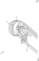
7 eine schematische perspektivische Darstellung eines Abschnitts eines Roboterarms der Bodeneinheit, wobei der Roboterarm den Kontaktkopf trägt, -
8 eine schematische perspektivische Darstellung der Ladevorrichtung von unten, wobei der den Kontaktkopf tragende Roboterarm der Bodeneinheit den Kontaktkopf in die geöffnete Aufnahme der Fahrzeugeinheit eingeführt hat und entsprechend die Bodeneinheit mit der Fahrzeugeinheit verbunden ist, -
9a eine schematische perspektivische Darstellung der Kontaktarme und des Kontaktkopfes in einer geöffneten Stellung, -
9b eine schematische perspektivische Darstellung der Kontaktarme und des Kontaktkopfes in einer geschlossenen Stellung, in welcher eine Kontaktierung der Kontakte des Kontaktkopfes mit den Kontakten der Kontaktarme hergestellt ist, -
10a eine schematische Seitenansicht der Kontaktarme und des Kontaktkopfes in einer geöffneten Stellung, -
10b eine schematische Seitenansicht der Kontaktarme und des Kontaktkopfes in einer geschlossenen Stellung, -
11 eine schematische perspektivische Darstellung eines Kontaktkopfes in einer weiteren Ausführungsform mit sechs übereinander angeordneten Kontakten und einem entsprechenden Kontaktarm, und -
12 eine schematische perspektivische Darstellung eines Kontaktkopfes in einer weiteren Ausführungsform in Form eines liegenden Zylinders und einem entsprechenden Kontaktarm.
-
1 a schematic perspective view of a vehicle unit from below with a cover in a closed position, -
2 a schematic perspective illustration of the vehicle unit1 with the cover shown in an open position -
3 a schematic perspective illustration of contact arms for contacting a contact head that can be accommodated between them, a surrounding housing being omitted from the illustration, -
4a a schematic perspective view of the contact arms in an open position, -
4b a schematic perspective view of the contact arms in a closed position, -
5a a schematic top view of the contact arms in an open position, in which an insertion of a contact head is made possible, -
5b a schematic top view of the contact arms in a closed position, -
6th a schematic perspective illustration of a contact head of a floor unit, which can be received in a receptacle of the vehicle unit, wherein the contacts of the contact head can be contacted by means of the contact arms of the vehicle unit, -
7th a schematic perspective illustration of a section of a robot arm of the floor unit, wherein the robot arm carries the contact head, -
8th a schematic perspective view of the loading device from below, wherein the robot arm of the floor unit carrying the contact head has inserted the contact head into the open receptacle of the vehicle unit and the floor unit is correspondingly connected to the vehicle unit, -
9a a schematic perspective view of the contact arms and the contact head in an open position, -
9b a schematic perspective illustration of the contact arms and the contact head in a closed position, in which contact is made between the contacts of the contact head and the contacts of the contact arms, -
10a a schematic side view of the contact arms and the contact head in an open position, -
10b a schematic side view of the contact arms and the contact head in a closed position, -
11th a schematic perspective illustration of a contact head in a further embodiment with six contacts arranged one above the other and a corresponding contact arm, and -
12th a schematic perspective illustration of a contact head in a further embodiment in the form of a horizontal cylinder and a corresponding contact arm.
Detaillierte Beschreibung bevorzugter ausführungsbeispieleDetailed description of preferred exemplary embodiments
Im Folgenden werden bevorzugte Ausführungsbeispiele anhand der Figuren beschrieben. Dabei werden gleiche, ähnliche oder gleichwirkende Elemente in den unterschiedlichen Figuren mit identischen Bezugszeichen versehen, und auf eine wiederholte Beschreibung dieser Elemente wird teilweise verzichtet, um Redundanzen zu vermeiden.Preferred exemplary embodiments are described below with reference to the figures. Identical, similar or identically acting elements are provided with identical reference symbols in the different figures, and a repeated description of these elements is in some cases dispensed with in order to avoid redundancies.
In
Unter einem Elektrofahrzeug wird hierbei jedes Fahrzeug verstanden, welches eine Traktionsbatterie aufweist, die extern geladen werden kann - also neben reinen Elektrofahrzeugen beispielsweise auch Plugin-Hybrid Fahrzeuge.An electric vehicle is understood to mean any vehicle that has a traction battery that can be charged externally - that is, in addition to purely electric vehicles, for example also plug-in hybrid vehicles.
Über die Fahrzeugeinheit
Die Bodeneinheit
Die Fahrzeugeinheit
Die Ladevorrichtung
Dabei kann mittels der Ladevorrichtung
Vielmehr muss der Benutzer das Elektrofahrzeug lediglich über einer am Boden des Abstellplatzes für das Elektrofahrzeug angeordneten Bodeneinheit positionieren und dort abstellen. Die restlichen Schritte des mechanischen und elektrischen Kontaktierungsvorgangs sowie des Ladevorgangs finden dann ohne weitere Tätigkeiten des Benutzers statt.Rather, the user only has to position the electric vehicle above a floor unit arranged on the floor of the parking space for the electric vehicle and park it there. The remaining steps of the mechanical and electrical contacting process as well as the charging process then take place without any further activities on the part of the user.
Mit anderen Worten kann eine automatische Kommunikation zwischen dem zu ladenden Elektrofahrzeug und der Ladevorrichtung stattfinden und, wenn beispielsweise ein vorgegebener Ladezustand des Elektrofahrzeugs unterschritten wird, automatisch ein Ladevorgang gestartet werden. Es kann allerdings auch vorgesehen sein, dass der Benutzer den Ladevorgang aktiv anstößt, dann aber zumindest keine weitere manuelle Interaktion zwischen dem Benutzer und der Ladevorrichtung notwendig ist.In other words, automatic communication between the electric vehicle to be charged and the charging device can take place and, for example, if the charging state of the electric vehicle falls below a specified level, a charging process can be started automatically. It can, however, also be provided that the user actively initiates the charging process, but then at least no further manual interaction between the user and the charging device is necessary.
Die Bodeneinheit stellt dann über ein nachfolgend beschriebenes Kontaktierungsverfahren einen physischen Kontakt mit dem Elektrofahrzeug her, um auf diese Weise einen Ladestrom zum Laden der Traktionsbatterie des Elektrofahrzeuges bereitstellen zu können. Insbesondere wird ein Kontaktkopf der Bodeneinheit mit einem oder mehreren Kontaktarmen der Fahrzeugeinheit verbunden und auf diese Weise ein elektrischer Kontakt hergestellt. Entsprechend kann mittels der Ladevorrichtung ein besonders bequemes Betreiben eines mit einem Elektromotor und einer dazugehörigen Traktionsbatterie versehenen Elektrofahrzeugs ermöglicht werden, bei welchem der Benutzer nach dem Abstellen des Elektrofahrzeugs über der Bodeneinheit und möglicherweise einem Anstoßen des Ladevorganges keine weiteren Schritte mehr unternehmen muss, da die Ladevorrichtung dies automatisch und selbstständig vornimmt.The ground unit then uses a contacting method described below to establish physical contact with the electric vehicle in order to be able to provide a charging current for charging the traction battery of the electric vehicle in this way. In particular, a contact head of the floor unit is connected to one or more contact arms of the vehicle unit and an electrical contact is established in this way. Accordingly, a particularly convenient operation of an electric vehicle provided with an electric motor and an associated traction battery can be made possible by means of the charging device, in which the user does not have to take any further steps after parking the electric vehicle above the floor unit and possibly initiating the charging process, since the charging device does this automatically and independently.
Es ist insbesondere nicht notwendig, dass der Benutzer des Elektrofahrzeuges zur Verbindung der Traktionsbatterie mit einer Stromquelle manuell ein Ladekabel mit einem Stecker von einer Ladesäule oder einem Wallbox zu dem Elektrofahrzeug führen muss und dann ein entsprechendes Einstecken vornehmen muss, sondern dieser manuelle Prozess kann fortfallen.In particular, it is not necessary for the user of the electric vehicle to manually lead a charging cable with a plug from a charging station or a wallbox to the electric vehicle in order to connect the traction battery to a power source and then to plug it in accordingly, but this manual process can be omitted.
Gleichermaßen kann über die vorgeschlagene Ladevorrichtung auch vermieden werden, dass bei noch bestehender Kontaktierung des Elektrofahrzeugs ein Benutzer bereits losfahren möchte und dann noch einmal aussteigen muss, um dann die versehentlich noch bestehende Verbindung zu lösen. Mittels der vorgeschlagenen Ladevorrichtung kann vielmehr auch ein automatisches selbstständiges Trennen erreicht werden, welches beispielsweise dann durchgeführt wird, wenn der eigentliche Ladevorgang beendet wurde, also die Traktionsbatterie wieder vollständig gefüllt ist, oder aber angestoßen beispielsweise durch das Öffnen des Elektrofahrzeugs oder das Betreten des Innenraums des Elektrofahrzeugs oder das Einschalten der „Zündung“ des Elektrofahrzeugs. Mit anderen Worten muss ein Benutzer auch zum Trennen der bestehenden Kontaktierung der Ladevorrichtung keine aktiven Schritte unternehmen. Es kann jedoch auch vorgesehen sein, dass der Benutzer ein aktives Trennen durch einen entsprechenden Trennbefehl vorgibt. Auf jeden Fall muss der Benutzer keine manuellen Schritte zum Trennen des Elektrofahrzeugs von der Stromversorgung vornehmen.Equally, the proposed charging device can also prevent a user from wanting to drive off while the electric vehicle is still in contact and then having to get out again in order to then inadvertently disconnect the connection. Rather, the proposed charging device can also be used to achieve automatic, independent disconnection, which is carried out, for example, when the actual charging process has ended, i.e. the traction battery is completely filled again, or triggered, for example, by opening the electric vehicle or entering the interior of the Electric vehicle or switching on the "ignition" of the electric vehicle. In other words, a user does not have to take any active steps to disconnect the existing contacting of the charging device. However, it can also be provided that the user specifies active disconnection by means of a corresponding disconnection command. In any case, the user does not need to take any manual steps to disconnect the electric vehicle from the power supply.
Die Fahrzeugeinheit
Die Fahrzeugeinheit
Die Abdeckung
Das Öffnen und das Verschließen der Abdeckung
In
Die Aufnahme
Die Aufnahme
Die geometrische Ausbildung der Aufnahme
Der Stift
Um eine laterale beziehungsweise radiale Führung zu erreichen, kann der Stift
An Seitenwänden des Gehäuses
Das Gehäuse
In
Die beiden Kontaktarme
Dabei sind beide Kontaktarme
Eine symmetrische Ausbildung der jeweils drei Kontaktelementen
In
In
In
Nach dem Einführen des Kontaktkopfes
In
In
An dem anderen Ende stehen die Kontaktarme mittels Drehgelenken
Die Kontaktarme
Eine Montage der Kontaktarme
In
Mit anderen Worten sind die übereinanderliegenden Kontakte
Die Kontakte
Alternative Varianten des Kontaktkopfes
In
Statt einem Roboterarm kann auch eine andere Hubvorrichtung, welche den Kontaktkopf
Bei der gezeigten zylinderförmigen Ausbildung des Kontaktkopfes
In
Eine Kontaktierung zwischen dem Kontaktkopf
In
Eine exakte Rotation des Kontaktkopfes
Beispielsweise darf bei einem Vorsehen der Kontakte
In
Die
Zum Schluss sind in
In
In
Soweit anwendbar, können alle einzelnen Merkmale, die in den Ausführungsbeispielen dargestellt sind, miteinander kombiniert und/oder ausgetauscht werden, ohne den Bereich der Erfindung zu verlassen.As far as applicable, all of the individual features shown in the exemplary embodiments can be combined with one another and / or exchanged without departing from the scope of the invention.
BezugszeichenlisteList of reference symbols
- 11
- FahrzeugeinheitVehicle unit
- 100100
- LadevorrichtungLoading device
- 1010
- Gehäusecasing
- 22
- Abdeckungcover
- 2020th
- SchwenkachseSwivel axis
- 201201
- AntriebsachseDrive axle
- 202202
- Gehäuse der AbdeckungsantriebCover drive housing
- 2121
- VerriegelungshakenLocking hook
- 2222nd
- VerriegelungsöffnungLocking opening
- 33
- Aufnahmeadmission
- 3030th
- Gehäusecasing
- 3131
- Stiftpen
- 3232
- AusnehmungRecess
- 4L, 4R4L, 4R
- KontaktarmContact poor
- 41R, 41L41R, 41L
- FührungselementGuide element
- 42, 42R, 42L42, 42R, 42L
- KontaktelementContact element
- 43R, 43L43R, 43L
- FixierelementFixing element
- 432R, 432L432R, 432L
- DrehgelenkeSwivel joints
- 44R, 44L44R, 44L
- KoppelungselementCoupling element
- 441L, 441R441L, 441R
- DrehgelenkSwivel joint
- 4545
- LenkerHandlebars
- 45a, 45b45a, 45b
- DrehgelenkSwivel joint
- 4646
- AntriebsachseDrive axle
- 461461
- Gehäuse des AntriebsmechanismusHousing of the drive mechanism
- 47R, 47L47R, 47L
- Kabelcable
- 55
- KontaktkopfContact head
- 5050
- KontaktkopfgehäuseContact head housing
- 51R, 51L51R, 51L
- Kontaktecontacts
- PhiPhi
- Kreisabschnitt von KontaktleiterbahnenCircle section of contact conductor tracks
- 52R, 52L52R, 52L
- LeiterbahnTrack
- 66th
- BodeneinheitGround unit
- 6161
- VerbindungselementConnecting element
- 6262
- RoboterarmRobotic arm
- 6363
- LadekabelCharging cable
- ZZ
- EinführrichtungDirection of insertion
ZITATE ENTHALTEN IN DER BESCHREIBUNGQUOTES INCLUDED IN THE DESCRIPTION
Diese Liste der vom Anmelder aufgeführten Dokumente wurde automatisiert erzeugt und ist ausschließlich zur besseren Information des Lesers aufgenommen. Die Liste ist nicht Bestandteil der deutschen Patent- bzw. Gebrauchsmusteranmeldung. Das DPMA übernimmt keinerlei Haftung für etwaige Fehler oder Auslassungen.This list of the documents listed by the applicant was generated automatically and is included solely for the better information of the reader. The list is not part of the German patent or utility model application. The DPMA assumes no liability for any errors or omissions.
Zitierte PatentliteraturPatent literature cited
- DE 102014200290 A1 [0007]DE 102014200290 A1 [0007]
- WO 18055498 A2 [0008]WO 18055498 A2 [0008]
- DE 102014226357 A1 [0009]DE 102014226357 A1 [0009]
- WO 16119001 A1 [0010]WO 16119001 A1 [0010]
Claims (16)
Priority Applications (4)
| Application Number | Priority Date | Filing Date | Title |
|---|---|---|---|
| DE102020116623.0A DE102020116623A1 (en) | 2020-06-24 | 2020-06-24 | Vehicle unit and ground unit for charging a battery of an electric vehicle |
| US18/003,288 US20230241988A1 (en) | 2020-06-24 | 2021-06-24 | Vehicle unit, ground unit and method for charging a battery of an electric vehicle |
| PCT/EP2021/067384 WO2021260132A1 (en) | 2020-06-24 | 2021-06-24 | Vehicle unit, ground unit and method for charging a battery of an electric vehicle |
| CN202180045063.7A CN115734892A (en) | 2020-06-24 | 2021-06-24 | Vehicle unit and ground unit for charging the battery of an electric vehicle |
Applications Claiming Priority (1)
| Application Number | Priority Date | Filing Date | Title |
|---|---|---|---|
| DE102020116623.0A DE102020116623A1 (en) | 2020-06-24 | 2020-06-24 | Vehicle unit and ground unit for charging a battery of an electric vehicle |
Publications (1)
| Publication Number | Publication Date |
|---|---|
| DE102020116623A1 true DE102020116623A1 (en) | 2021-12-30 |
Family
ID=76765125
Family Applications (1)
| Application Number | Title | Priority Date | Filing Date |
|---|---|---|---|
| DE102020116623.0A Ceased DE102020116623A1 (en) | 2020-06-24 | 2020-06-24 | Vehicle unit and ground unit for charging a battery of an electric vehicle |
Country Status (4)
| Country | Link |
|---|---|
| US (1) | US20230241988A1 (en) |
| CN (1) | CN115734892A (en) |
| DE (1) | DE102020116623A1 (en) |
| WO (1) | WO2021260132A1 (en) |
Cited By (3)
| Publication number | Priority date | Publication date | Assignee | Title |
|---|---|---|---|---|
| WO2023151940A1 (en) | 2022-02-14 | 2023-08-17 | Gulplug | Socket with radial electrical connection |
| WO2024132054A1 (en) * | 2022-12-23 | 2024-06-27 | Continental Engineering Services Gmbh | Plug arrangement with a support, for an electric vehicle |
| WO2025026496A1 (en) * | 2023-08-01 | 2025-02-06 | Schaeffler Technologies AG & Co. KG | Conductive charging system comprising a lid closure |
Families Citing this family (2)
| Publication number | Priority date | Publication date | Assignee | Title |
|---|---|---|---|---|
| US12531305B2 (en) | 2024-06-20 | 2026-01-20 | Estes Energy Solutions, Inc. | Thermo-structural battery packs and systems |
| US12555840B2 (en) | 2024-06-20 | 2026-02-17 | Estes Energy Solutions, Inc. | Thermo-structural battery packs and systems |
Citations (8)
| Publication number | Priority date | Publication date | Assignee | Title |
|---|---|---|---|---|
| US20030127153A1 (en) | 2002-01-10 | 2003-07-10 | Mulvenna Alan John | Service coupling |
| US20100173534A1 (en) | 2008-03-14 | 2010-07-08 | Shihwei Tung | Socket |
| DE102014200290A1 (en) | 2014-01-10 | 2015-07-16 | Robert Bosch Gmbh | Electric charging device, electrical connection device, system and method for charging a battery of a vehicle |
| DE102014226357A1 (en) | 2014-12-18 | 2016-06-23 | Robert Bosch Gmbh | Charging station and method for automatically charging an electrical energy store in a vehicle |
| WO2016119001A1 (en) | 2015-01-30 | 2016-08-04 | Flechl Christian | Plug-in connection and method for connecting, in particular, electrical lines |
| WO2018055498A2 (en) | 2016-09-20 | 2018-03-29 | Dazetechnology S.R.L. | Power equipment for electric vehicles |
| DE102017115224A1 (en) | 2017-07-07 | 2019-01-10 | Paxos Consulting & Engineering GmbH & Co. KG | Charging plug and charging plug charging socket system for charging an electric vehicle |
| DE102019125783A1 (en) | 2019-09-25 | 2019-12-05 | Audi Ag | Energy supply arrangement for supplying a motor vehicle with electrical energy via a conductive plug connection and method for operating a power supply arrangement |
Family Cites Families (12)
| Publication number | Priority date | Publication date | Assignee | Title |
|---|---|---|---|---|
| US6817879B2 (en) * | 2001-11-26 | 2004-11-16 | General Hydrogen Corporation | Service port configurations |
| DE112011106154B4 (en) * | 2010-07-16 | 2024-05-02 | Panasonic Intellectual Property Management Co., Ltd. | Contact device |
| US9266440B2 (en) * | 2011-09-26 | 2016-02-23 | GM Global Technology Operations LLC | Robotically operated vehicle charging station |
| CN105375196B (en) * | 2015-12-09 | 2017-12-22 | 云杉智慧新能源技术有限公司 | Electrical conduction attachment means |
| JP6622252B2 (en) * | 2017-06-09 | 2019-12-18 | 矢崎総業株式会社 | Connector device |
| AT520449B1 (en) * | 2017-09-27 | 2019-04-15 | Nrg X Charging Systems Gmbh | Component for a charging device and charging device hereby |
| EP3552866B1 (en) * | 2018-04-11 | 2021-12-01 | Iveco S.p.A. | Recharge system for an electric vehicle |
| CN208585109U (en) * | 2018-08-13 | 2019-03-08 | 环球车享汽车租赁有限公司 | Charging coupler in stereo garage |
| US20210387539A1 (en) * | 2018-10-31 | 2021-12-16 | Hirschmann Automotive Gmbh | Conductive charger with centering system |
| US10518658B1 (en) * | 2018-11-06 | 2019-12-31 | Abb Schweiz Ag | Electrical vehicle battery recharging vehicle-side receptacle unit |
| US11318857B2 (en) * | 2019-11-01 | 2022-05-03 | Ford Global Technologies, Llc | System for hands-free electrified vehicle charging |
| CN111082240B (en) * | 2019-11-27 | 2025-07-29 | 青岛特来电新能源科技有限公司 | Conductive connection structure of charging plug, charging plug and charging terminal |
-
2020
- 2020-06-24 DE DE102020116623.0A patent/DE102020116623A1/en not_active Ceased
-
2021
- 2021-06-24 WO PCT/EP2021/067384 patent/WO2021260132A1/en not_active Ceased
- 2021-06-24 CN CN202180045063.7A patent/CN115734892A/en active Pending
- 2021-06-24 US US18/003,288 patent/US20230241988A1/en active Pending
Patent Citations (8)
| Publication number | Priority date | Publication date | Assignee | Title |
|---|---|---|---|---|
| US20030127153A1 (en) | 2002-01-10 | 2003-07-10 | Mulvenna Alan John | Service coupling |
| US20100173534A1 (en) | 2008-03-14 | 2010-07-08 | Shihwei Tung | Socket |
| DE102014200290A1 (en) | 2014-01-10 | 2015-07-16 | Robert Bosch Gmbh | Electric charging device, electrical connection device, system and method for charging a battery of a vehicle |
| DE102014226357A1 (en) | 2014-12-18 | 2016-06-23 | Robert Bosch Gmbh | Charging station and method for automatically charging an electrical energy store in a vehicle |
| WO2016119001A1 (en) | 2015-01-30 | 2016-08-04 | Flechl Christian | Plug-in connection and method for connecting, in particular, electrical lines |
| WO2018055498A2 (en) | 2016-09-20 | 2018-03-29 | Dazetechnology S.R.L. | Power equipment for electric vehicles |
| DE102017115224A1 (en) | 2017-07-07 | 2019-01-10 | Paxos Consulting & Engineering GmbH & Co. KG | Charging plug and charging plug charging socket system for charging an electric vehicle |
| DE102019125783A1 (en) | 2019-09-25 | 2019-12-05 | Audi Ag | Energy supply arrangement for supplying a motor vehicle with electrical energy via a conductive plug connection and method for operating a power supply arrangement |
Cited By (6)
| Publication number | Priority date | Publication date | Assignee | Title |
|---|---|---|---|---|
| WO2023151940A1 (en) | 2022-02-14 | 2023-08-17 | Gulplug | Socket with radial electrical connection |
| FR3132797A1 (en) * | 2022-02-14 | 2023-08-18 | Gulplug | Plug with radial electrical connection |
| WO2024132054A1 (en) * | 2022-12-23 | 2024-06-27 | Continental Engineering Services Gmbh | Plug arrangement with a support, for an electric vehicle |
| WO2025026496A1 (en) * | 2023-08-01 | 2025-02-06 | Schaeffler Technologies AG & Co. KG | Conductive charging system comprising a lid closure |
| DE102023120349A1 (en) * | 2023-08-01 | 2025-02-06 | Schaeffler Technologies AG & Co. KG | Conductive charging system with lid closure |
| DE102023120349B4 (en) * | 2023-08-01 | 2025-05-22 | Schaeffler Technologies AG & Co. KG | Conductive charging system with lid closure |
Also Published As
| Publication number | Publication date |
|---|---|
| US20230241988A1 (en) | 2023-08-03 |
| WO2021260132A1 (en) | 2021-12-30 |
| CN115734892A (en) | 2023-03-03 |
Similar Documents
| Publication | Publication Date | Title |
|---|---|---|
| DE102020116623A1 (en) | Vehicle unit and ground unit for charging a battery of an electric vehicle | |
| DE102019203193B4 (en) | Connector assembly for connecting and disconnecting electrical wires | |
| DE19739795C2 (en) | Electrical connection device | |
| DE102022202182B4 (en) | Charging socket and charging plug for automated charging of electric vehicles | |
| DE102019205548B4 (en) | Charging connector system for an electric vehicle | |
| WO2013030265A2 (en) | Device for establishing and disconnecting a charging connection for a plug-in vehicle in an automated manner | |
| DE102019122051A1 (en) | Vehicle unit with a charging connection and charging device for charging a battery of an electric vehicle | |
| DE102016207767B4 (en) | Automatic plugging of a charging plug for an electric vehicle | |
| WO2012136328A2 (en) | Locking system for a plug coupling device arranged on a motor vehicle, a charging station or a wall | |
| WO2021094477A1 (en) | Vehicle unit comprising a charging connection, and charging system for charging a battery of an electric vehicle | |
| EP3628579B1 (en) | Driving device for an electric bicycle with pivotable motor plug-in connector | |
| EP4422915A1 (en) | Charging connection device for an electrically drivable vehicle | |
| DE102010041362A1 (en) | Charging device for charging rechargeable battery of electric car at charging station, has electrical connector mechanically connected with loading station in electrically conducting manner in one operating position | |
| EP4279326A1 (en) | Docking station, charging system, computer program product and method | |
| EP3847725A1 (en) | Electrical plug-in connection, vehicle and method for locking an electrical plug-in connection | |
| EP4419378A1 (en) | Charging terminal device for an electrically drivable vehicle | |
| DE102020132723A1 (en) | Connector holder | |
| EP4422916A1 (en) | Charging connection device for a vehicle which can be electrically driven | |
| EP3820731B1 (en) | Charging device for charging a battery of an electrically operated motor vehicle | |
| DE102021130602A1 (en) | Loading device and method for opening a protective flap of a loading device | |
| DE3151560A1 (en) | Arrangement for automatically connecting a coupling part assigned to a vehicle and a stationary coupling part for an electrical connecting line, and a plug-in coupling for this | |
| DE102011110577A1 (en) | Locking device for locking charging power socket to e.g. passenger car, has monitoring unit for monitoring locking element in locked position, where position of locking element is detected by position of moving element | |
| DE102020200292B4 (en) | Device and method for automatically charging an electrically powered motor vehicle | |
| DE102019007060A1 (en) | Charging device for electrical connection to a charging port of a motor vehicle | |
| DE102023118323A1 (en) | Connection unit with guide elements for connecting a charging plug to an electric vehicle, as well as electric vehicle |
Legal Events
| Date | Code | Title | Description |
|---|---|---|---|
| R012 | Request for examination validly filed | ||
| R016 | Response to examination communication | ||
| R082 | Change of representative |
Representative=s name: MAUCHER JENKINS PATENTANWAELTE & RECHTSANWAELT, DE |
|
| R002 | Refusal decision in examination/registration proceedings | ||
| R003 | Refusal decision now final |