DE102020112694A1 - Load-bearing component of a body of a passenger vehicle - Google Patents
Load-bearing component of a body of a passenger vehicle Download PDFInfo
- Publication number
- DE102020112694A1 DE102020112694A1 DE102020112694.8A DE102020112694A DE102020112694A1 DE 102020112694 A1 DE102020112694 A1 DE 102020112694A1 DE 102020112694 A DE102020112694 A DE 102020112694A DE 102020112694 A1 DE102020112694 A1 DE 102020112694A1
- Authority
- DE
- Germany
- Prior art keywords
- load
- bearing component
- vehicle
- component
- cast
- Prior art date
- Legal status (The legal status is an assumption and is not a legal conclusion. Google has not performed a legal analysis and makes no representation as to the accuracy of the status listed.)
- Pending
Links
- 230000003014 reinforcing effect Effects 0.000 claims description 21
- 230000002787 reinforcement Effects 0.000 claims description 16
- 229910052751 metal Inorganic materials 0.000 claims description 5
- 239000002184 metal Substances 0.000 claims description 5
- 238000003860 storage Methods 0.000 claims description 5
- 239000000725 suspension Substances 0.000 claims description 2
- 238000000034 method Methods 0.000 abstract description 5
- 239000000463 material Substances 0.000 description 6
- 230000010354 integration Effects 0.000 description 4
- XEEYBQQBJWHFJM-UHFFFAOYSA-N Iron Chemical compound [Fe] XEEYBQQBJWHFJM-UHFFFAOYSA-N 0.000 description 2
- 239000006096 absorbing agent Substances 0.000 description 2
- 229910045601 alloy Inorganic materials 0.000 description 2
- 239000000956 alloy Substances 0.000 description 2
- 238000004519 manufacturing process Methods 0.000 description 2
- 238000005457 optimization Methods 0.000 description 2
- 230000035939 shock Effects 0.000 description 2
- 239000013585 weight reducing agent Substances 0.000 description 2
- BUHVIAUBTBOHAG-FOYDDCNASA-N (2r,3r,4s,5r)-2-[6-[[2-(3,5-dimethoxyphenyl)-2-(2-methylphenyl)ethyl]amino]purin-9-yl]-5-(hydroxymethyl)oxolane-3,4-diol Chemical compound COC1=CC(OC)=CC(C(CNC=2C=3N=CN(C=3N=CN=2)[C@H]2[C@@H]([C@H](O)[C@@H](CO)O2)O)C=2C(=CC=CC=2)C)=C1 BUHVIAUBTBOHAG-FOYDDCNASA-N 0.000 description 1
- FYYHWMGAXLPEAU-UHFFFAOYSA-N Magnesium Chemical compound [Mg] FYYHWMGAXLPEAU-UHFFFAOYSA-N 0.000 description 1
- 229910000861 Mg alloy Inorganic materials 0.000 description 1
- 229910052782 aluminium Inorganic materials 0.000 description 1
- XAGFODPZIPBFFR-UHFFFAOYSA-N aluminium Chemical compound [Al] XAGFODPZIPBFFR-UHFFFAOYSA-N 0.000 description 1
- SNAAJJQQZSMGQD-UHFFFAOYSA-N aluminum magnesium Chemical compound [Mg].[Al] SNAAJJQQZSMGQD-UHFFFAOYSA-N 0.000 description 1
- 238000000418 atomic force spectrum Methods 0.000 description 1
- 238000010276 construction Methods 0.000 description 1
- 238000004512 die casting Methods 0.000 description 1
- 238000009826 distribution Methods 0.000 description 1
- 230000000694 effects Effects 0.000 description 1
- 238000005265 energy consumption Methods 0.000 description 1
- 229910052742 iron Inorganic materials 0.000 description 1
- 229910052749 magnesium Inorganic materials 0.000 description 1
- 239000011777 magnesium Substances 0.000 description 1
- 150000002739 metals Chemical class 0.000 description 1
- 239000007787 solid Substances 0.000 description 1
- 230000007704 transition Effects 0.000 description 1
Images


Classifications
-
- B—PERFORMING OPERATIONS; TRANSPORTING
- B62—LAND VEHICLES FOR TRAVELLING OTHERWISE THAN ON RAILS
- B62D—MOTOR VEHICLES; TRAILERS
- B62D25/00—Superstructure or monocoque structure sub-units; Parts or details thereof not otherwise provided for
- B62D25/20—Floors or bottom sub-units
- B62D25/2009—Floors or bottom sub-units in connection with other superstructure subunits
- B62D25/2027—Floors or bottom sub-units in connection with other superstructure subunits the subunits being rear structures
-
- B—PERFORMING OPERATIONS; TRANSPORTING
- B62—LAND VEHICLES FOR TRAVELLING OTHERWISE THAN ON RAILS
- B62D—MOTOR VEHICLES; TRAILERS
- B62D25/00—Superstructure or monocoque structure sub-units; Parts or details thereof not otherwise provided for
- B62D25/08—Front or rear portions
-
- B—PERFORMING OPERATIONS; TRANSPORTING
- B62—LAND VEHICLES FOR TRAVELLING OTHERWISE THAN ON RAILS
- B62D—MOTOR VEHICLES; TRAILERS
- B62D27/00—Connections between superstructure or understructure sub-units
- B62D27/02—Connections between superstructure or understructure sub-units rigid
- B62D27/023—Assembly of structural joints
-
- B—PERFORMING OPERATIONS; TRANSPORTING
- B62—LAND VEHICLES FOR TRAVELLING OTHERWISE THAN ON RAILS
- B62D—MOTOR VEHICLES; TRAILERS
- B62D29/00—Superstructures, understructures, or sub-units thereof, characterised by the material thereof
- B62D29/008—Superstructures, understructures, or sub-units thereof, characterised by the material thereof predominantly of light alloys, e.g. extruded
Landscapes
- Engineering & Computer Science (AREA)
- Chemical & Material Sciences (AREA)
- Combustion & Propulsion (AREA)
- Transportation (AREA)
- Mechanical Engineering (AREA)
- Architecture (AREA)
- Structural Engineering (AREA)
- Body Structure For Vehicles (AREA)
Abstract
Es ist ein tragendes Bauteil einer Karosserie eines Personenkraftfahrzeugs bekannt, das einen Seitenschweller einer Fahrgastzelle mit einem Hecklängsträger verbindet. Das tragende Bauteil ist als Gussbauteil ausgebildet, das einen C-förmigen Querschnitt aufweist, der zur Fahrzeugseite hin offen ist. Aufgabe der Erfindung ist es, ein tragendes Bauteil einer Karosserie eines Personenkraftfahrzeugs so zu gestalten, dass es einerseits viele Funktionen in sich vereint und andererseits ein geringes Gewicht aufweist.Erfindungsgemäß weist ein tragendes Bauteil (1) einer Karosserie eines Personenkraftfahrzeugs zumindest einen flächigen Abschnitt auf, der zumindest in einem Bereich eine Aussparung (12) aufweist. Dabei befindet sich die Aussparung (12) in einem Bereich, der bei der Verwendung des tragenden Karosseriebauteils (1) in der Karosserie besonders geringen Beanspruchungen ausgesetzt ist. Diese Bereiche lassen sich beispielsweise mit Hilfe der Finite-Elemente-Methode in einem Simulationsprogramm ermitteln.A load-bearing component of a body of a passenger vehicle is known which connects a side sill of a passenger compartment to a rear side member. The load-bearing component is designed as a cast component that has a C-shaped cross section that is open to the side of the vehicle. The object of the invention is to design a load-bearing component of a body of a passenger vehicle in such a way that on the one hand it combines many functions and on the other hand has a low weight. According to the invention, a load-bearing component (1) of a body of a passenger vehicle has at least one flat section, which has a recess (12) in at least one area. The recess (12) is located in an area which is exposed to particularly low stresses when the load-bearing body component (1) is used in the body. These areas can be determined in a simulation program using the finite element method, for example.
Description
Die Erfindung betrifft ein tragendes Bauteil einer Karosserie eines Personenkraftfahrzeugs nach dem Oberbegriff des Patentanspruchs 1.The invention relates to a load-bearing component of a body of a passenger vehicle according to the preamble of
Aus der
Aufgabe der Erfindung ist es, ein tragendes Bauteil einer Karosserie eines Personenkraftfahrzeugs so zu gestalten, dass es einerseits viele Funktionen in sich vereint und andererseits ein geringes Gewicht aufweist.The object of the invention is to design a load-bearing component of a body of a passenger vehicle in such a way that, on the one hand, it combines many functions and, on the other hand, has a low weight.
Diese Aufgabe wird mit einem tragenden Bauteil einer Karosserie eines Personenkraftfahrzeugs mit den Merkmalen des Patentanspruchs 1 gelöst.This object is achieved with a load-bearing component of a body of a passenger vehicle with the features of
Erfindungsgemäß weist ein tragendes Bauteil einer Karosserie eines Personenkraftfahrzeugs zumindest einen flächigen Abschnitt auf, der zumindest in einem Bereich eine Aussparung aufweist. Dabei befindet sich die zumindest eine Aussparung in einem Bereich, der bei bestimmungsgemäßer Verwendung des tragenden Karosseriebauteils in der Karosserie besonders geringen Beanspruchungen ausgesetzt ist. According to the invention, a load-bearing component of a body of a passenger vehicle has at least one flat section which has a recess in at least one area. The at least one recess is located in an area which is exposed to particularly low stresses when the load-bearing body component is used as intended in the body.
Diese Bereiche lassen sich beispielsweise mit Hilfe der Finite-Elemente-Methode in einem Simulationsprogramm ermitteln. Durch das Vorsehen der zumindest einen Aussparung kann das Gewicht des tragenden Bauteils reduziert werden, ohne seine Steifigkeit spürbar zu beeinträchtigen.These areas can be determined in a simulation program using the finite element method, for example. By providing the at least one recess, the weight of the load-bearing component can be reduced without noticeably impairing its rigidity.
Bevorzugt ist das tragende Bauteil ein Gussbauteil, das einen Seitenschweller der Fahrgastzelle des Personenkraftfahrzeugs mit einem sich in Fahrzeuglängsrichtung erstreckenden Hecklängsträger verbindet, der sich hinter der Fahrgastzelle in Fahrzeuglängsrichtung gesehen nach hinten erstreckt. Am hinteren Endbereich des Hecklängsträgers ist ein hinterer Stoßfänger bzw. ein Heckmodul befestigt, das zugleich als hinterer Stoßfänger dient. Das tragende Bauteil verläuft dabei zwischen dem Seitenschweller und dem Hecklängsträger entlang eines Radhauses und bildet zugleich eine Aufnahme für ein Federbein der Hinterachse des Personenkraftfahrzeugs. Dazu kann der Bereich der Aufnahme des Federbeins topfförmig gestaltet sein. Günstigerweise wird der flächige Abschnitt, in dem sich die zumindest eine Aussparung befindet, von einem bogenförmigen Wandabschnitt dieser topfförmigen Federbeinaufnahme gebildet. Insbesondere eignet sich der in Fahrzeugquerrichtung gesehen der Fahrzeugaußenseite zugewandte Wandabschnitt der Federbeinaufnahme für das Vorsehen der zumindest einen Aussparung.The load-bearing component is preferably a cast component which connects a side sill of the passenger compartment of the passenger vehicle with a rear side member extending in the longitudinal direction of the vehicle, which extends behind the passenger compartment in the longitudinal direction of the vehicle. A rear bumper or a rear module, which also serves as a rear bumper, is attached to the rear end area of the rear side member. The load-bearing component runs between the side sill and the rear side member along a wheel house and at the same time forms a receptacle for a suspension strut of the rear axle of the passenger vehicle. For this purpose, the area of the receptacle of the spring strut can be designed in the shape of a pot. The flat section in which the at least one recess is located is favorably formed by an arcuate wall section of this cup-shaped spring strut receptacle. In particular, the wall section of the spring strut receptacle facing the outside of the vehicle, viewed in the transverse direction of the vehicle, is suitable for providing the at least one recess.
Das tragende Gussbauteil weist idealerweise zumindest in einem Abschnitt einen C-förmigen Querschnitt auf, der in Fahrzeugquerrichtung gesehen zur Fahrzeugaußenseite hin offen ist. Dieser C-förmige Abschnitt befindet sich bevorzugt im vorderen Bereich, in dem auch der Seitenschweller angebunden ist.The load-bearing cast component ideally has a C-shaped cross section, at least in one section, which, viewed in the transverse direction of the vehicle, is open to the outside of the vehicle. This C-shaped section is preferably located in the front area, in which the side sill is also connected.
Idealerweise weist das tragende Bauteil im Bereich des flächigen Abschnitts zumindest auf einer Seite Versteifungsrippen auf, die von dem flächigen Abschnitt abstehen. Die zumindest eine Aussparung befindet sich günstigerweise in einem Bereich, der zwischen mehreren Versteifungsrippen liegt, sodass keine Versteifungsrippe über die Aussparung verläuft. Bevorzugt ist der flächige Abschnitt mit mehreren Versteifungsrippen verstärkt, die sich kreuzen oder eine Art Netz bilden. In diesem Fall ist die zumindest eine Aussparung idealerweise in einem Bereich angeordnet, der vollständig mit Versteifungsrippen umgeben ist.Ideally, in the area of the flat section, the load-bearing component has stiffening ribs on at least one side, which protrude from the flat section. The at least one recess is advantageously located in an area that lies between a plurality of stiffening ribs, so that no stiffening rib runs over the recess. The flat section is preferably reinforced with several stiffening ribs which intersect or form a type of network. In this case, the at least one recess is ideally arranged in an area that is completely surrounded by stiffening ribs.
Bevorzugt weist das tragende Bauteil zumindest eine Verstärkungsrippe auf, die einen vom tragenden Bauteil abstehenden freien Randbereich aufweist, der dem flächigen Abschnitt gegenüberliegt. Dieser freie Randbereich hat einen bogenförmigen Verlauf, der Abstand zwischen dem tragenden Bauteil und dem freien Randbereich verändert sich somit entlang der Längserstreckung der Verstärkungsrippe kontinuierlich. Der bogenförmige Verlauf ermöglicht gegenüber einer klassischen Versteifungsrippe mit einem geraden Verlauf des freien Randbereichs eine Materialeinsparung. Dazu sind Verstärkungsrippen konkav und/oder konvex gestaltet, sodass die Gestaltung dem Kraftverlauf entspricht. Dies geht mit einer Materialeinsparung an der Versteifungsrippe und somit einer Gewichtsreduzierung des tragenden Bauteils einher, ohne dass damit ein Steifigkeitsverlust verbunden ist.The load-bearing component preferably has at least one reinforcement rib which has a free edge region which protrudes from the load-bearing component and lies opposite the flat section. This free edge area has an arcuate course, the distance between the load-bearing component and the free edge area thus changes continuously along the longitudinal extension of the reinforcing rib. Compared to a classic stiffening rib with a straight course of the free edge area, the arched course enables material savings. For this purpose, reinforcement ribs are designed concave and / or convex, so that the design corresponds to the force curve. This goes hand in hand with a material saving on the stiffening rib and thus a weight reduction of the load-bearing component, without a loss of rigidity being associated with it.
In einer weiteren vorteilhaften Ausgestaltung weist das tragende Bauteil eine ringförmige Verstärkungsrippe auf, also eine Rippe, die einen mittleren Bereich vollständig ringförmig umgibt. Zusätzlich können sich weitere Verstärkungsrippen sternförmig von dieser ringförmigen Verstärkungsrippe aus nach außen erstrecken. Eine solche ringförmige Verstärkungsrippe kann gut in sie eingeleitete Kräfte verteilen und über die angrenzenden sternförmig verlaufenden Verstärkungsrippen ableiten.In a further advantageous embodiment, the load-bearing component has an annular reinforcing rib, that is to say a rib which completely surrounds a central region in an annular manner. In addition, further reinforcement ribs can extend outward in a star shape from this annular reinforcement rib. Such an annular reinforcing rib can easily introduce forces into it distribute and derive over the adjacent star-shaped reinforcing ribs.
Günstigerweise besteht das tragende Bauteil aus einem Leichtmetall. Hierfür bietet sich insbesondere Aluminium, Magnesium oder eine Legierung aus zumindest einem dieser beiden Metalle an. Diese Materialauswahl ermöglicht bei Verwendung der heute zur Verfügung stehenden Legierungen die Gestaltung eines sehr steifen Bauteils, das gegenüber einem vergleichbaren Bauteil aus einem Eisenwerkstoff ein deutlich geringeres Gewicht bei vergleichbarer Steifigkeit aufweist. Auch lässt sich ein solches Bauteil im Druckgussverfahren mit einer hohen Präzision herstellen, es weist also trotz der Größe des Bauteils nur sehr geringe Fertigungstoleranzen auf.The load-bearing component is advantageously made of a light metal. Aluminum, magnesium or an alloy made from at least one of these two metals are particularly suitable for this purpose. When using the alloys available today, this choice of material enables the design of a very rigid component which, compared to a comparable component made of an iron material, has a significantly lower weight with comparable rigidity. Such a component can also be manufactured with a high degree of precision using the die-casting process, so it has only very small manufacturing tolerances despite the size of the component.
Idealerweise ist in das tragende Bauteil einteilig zumindest ein Anbindungspunkt für einen Hochvoltspeicher integriert, der sich unterhalb einer Fahrgastzelle befindet. Ein solcher Hochvoltspeicher ist für moderne Fahrzeuge erforderlich, die zumindest auch einen elektrischen Antrieb aufweisen. Dabei muss der Hochvoltspeicher an einer Stelle angeordnet werden, die bei einem Unfall vergleichsweise gut geschützt ist, und die die fahrdynamischen Eigenschaften trotz des hohen Gewichts des Hochvoltspeichers möglichst wenig beeinflusst. Daher werden solche Hochvoltspeicher meist unterhalb der Fahrgastzelle angeordnet. Insbesondere bei einer Ausführung des tragenden Bauteils als Gussbauteil kann auf einfache Weise werkzeugfallend ein Anbindungspunkt für einen Hochvoltspeicher integriert werden. Ein solcher Anbindungspunkt muss aufgrund des hohen Gewichts des Hochvoltspeichers entsprechend steif ausgeführt sein. Der zumindest eine integrierte Anbindungspunkt kann günstigerweise mit Versteifungsrippen lokal verstärkt bzw. abgestützt ausgeführt sein.Ideally, at least one connection point for a high-voltage storage device, which is located below a passenger cell, is integrated in the load-bearing component in one piece. Such a high-voltage storage device is required for modern vehicles that at least also have an electric drive. The high-voltage battery must be located at a location that is comparatively well protected in the event of an accident and that has as little influence as possible on the dynamic properties of the vehicle despite the high weight of the high-voltage battery. This is why such high-voltage storage systems are usually arranged below the passenger compartment. In particular when the load-bearing component is embodied as a cast component, a connection point for a high-voltage storage device can be integrated in a simple manner without using a tool. Such a connection point must be designed to be correspondingly rigid due to the high weight of the high-voltage battery. The at least one integrated connection point can advantageously be locally reinforced or supported with stiffening ribs.
Des Weiteren kann günstigerweise eine Anbindung einer Rückenlehne in dieses tragende Bauteil integriert werden. Zusätzlich oder alternativ kann zudem eine Verstärkung einer Seitenwand des Personenkraftfahrzeugs einstückig mit dem tragenden Bauteil ausgeführt sein. Das tragende Bauteil befindet sich dabei im Übergangsbereich zwischen einem Fahrzeugboden und der Seitenwand. Durch eine steife Gestaltung des tragenden Bauteils wird somit zugleich die Verbindung zwischen dem Fahrzeugboden und der Seitenwand versteift, sodass dieser Bereich bei Torsionsbeanspruchungen in Fahrzeugquerrichtung sich weniger verwinden kann.Furthermore, a connection of a backrest can advantageously be integrated into this load-bearing component. Additionally or alternatively, a side wall of the passenger vehicle can also be reinforced in one piece with the load-bearing component. The load-bearing component is located in the transition area between a vehicle floor and the side wall. The connection between the vehicle floor and the side wall is thus stiffened at the same time through a rigid design of the load-bearing component, so that this area can twist less in the event of torsional loads in the transverse direction of the vehicle.
Auch ein Anbindungspunkt für ein Gurtschloss kann idealerweise in das tragende Bauteil integriert werden. Zusätzlich kann dieser Anbindungspunkt mindestens eine lokale Verstärkung aufweisen, die ebenfalls in das tragende Bauteil integriert sein kann.A connection point for a belt lock can also ideally be integrated into the load-bearing component. In addition, this connection point can have at least one local reinforcement, which can also be integrated into the load-bearing component.
Weitere vorteilhafte Ausgestaltungen sind Gegenstand von Unteransprüchen.Further advantageous configurations are the subject of subclaims.
In der Zeichnung ist ein Ausführungsbeispiel der Erfindung dargestellt, anhand dessen die Erfindung im Folgenden im Detail beschrieben wird. Die einzelnen Figuren zeigen in schematischer Darstellungsweise:
-
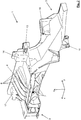
1 eine perspektivische Ansicht eines tragenden Gussbauteils einer Karosserie eines Personenkraftwagens, das einen Seitenschweller mit einem Hecklängsträger verbindet, -
2 eine weitere perspektivische Ansicht des in1 gezeigten Gussbauteils, -
3 eine Draufsicht auf das in1 und2 dargestellte Gussbauteil, -
4 eine Seitenansicht des in1 bis3 gezeigten Gussbauteils, -
5 eine Schnittansicht A - A des in4 gezeigten Gussbauteils und -
6 eine Ansicht des in1 bis5 gezeigten Gussbauteils von unten.
-
1 a perspective view of a load-bearing cast component of a body of a passenger car, which connects a side sill with a rear side member, -
2 a further perspective view of the in1 cast component shown, -
3 a top view of the in1 and2 Cast component shown, -
4th a side view of the in1 until3 cast component shown, -
5 a sectional view A - A of the in4th Cast component shown and -
6th a view of the in1 until5 Cast component shown from below.
In den Figuren ist in verschiedenen Ansichten ein Gussträger
Zudem bildet der Gussträger
Im Bereich hinter der Aufnahme
Ferner sind in den Gussträger
Des Weiteren ist in den Gussträger
Zusätzlich weist der Gussträger
Die Karosserie des Kraftfahrzeugs weist beidseitig jeweils einen solchen Gussträger
Der Gussträger
Der Gussträger
Eine weitere Möglichkeit zur Gewichtsoptimierung stellt die erfindungsgemäße Gestaltung der Versteifungsrippen
Die Versteifungsrippen
Eine dritte Möglichkeit zur Gewichtsoptimierung stellt die ringförmige Gestaltung zumindest einer Verstärkungsrippe
Eine genaue Analyse der tatsächlichen Beanspruchung des Gussträgers
ZITATE ENTHALTEN IN DER BESCHREIBUNGQUOTES INCLUDED IN THE DESCRIPTION
Diese Liste der vom Anmelder aufgeführten Dokumente wurde automatisiert erzeugt und ist ausschließlich zur besseren Information des Lesers aufgenommen. Die Liste ist nicht Bestandteil der deutschen Patent- bzw. Gebrauchsmusteranmeldung. Das DPMA übernimmt keinerlei Haftung für etwaige Fehler oder Auslassungen.This list of the documents listed by the applicant was generated automatically and is included solely for the better information of the reader. The list is not part of the German patent or utility model application. The DPMA assumes no liability for any errors or omissions.
Zitierte PatentliteraturPatent literature cited
- DE 102007006722 A1 [0002]DE 102007006722 A1 [0002]
Claims (13)
Priority Applications (1)
| Application Number | Priority Date | Filing Date | Title |
|---|---|---|---|
| DE102020112694.8A DE102020112694A1 (en) | 2020-05-11 | 2020-05-11 | Load-bearing component of a body of a passenger vehicle |
Applications Claiming Priority (1)
| Application Number | Priority Date | Filing Date | Title |
|---|---|---|---|
| DE102020112694.8A DE102020112694A1 (en) | 2020-05-11 | 2020-05-11 | Load-bearing component of a body of a passenger vehicle |
Publications (1)
| Publication Number | Publication Date |
|---|---|
| DE102020112694A1 true DE102020112694A1 (en) | 2021-11-11 |
Family
ID=78231807
Family Applications (1)
| Application Number | Title | Priority Date | Filing Date |
|---|---|---|---|
| DE102020112694.8A Pending DE102020112694A1 (en) | 2020-05-11 | 2020-05-11 | Load-bearing component of a body of a passenger vehicle |
Country Status (1)
| Country | Link |
|---|---|
| DE (1) | DE102020112694A1 (en) |
Citations (3)
| Publication number | Priority date | Publication date | Assignee | Title |
|---|---|---|---|---|
| DE10015325A1 (en) | 2000-03-28 | 2001-10-04 | Volkswagen Ag | Body component made of steel |
| DE10348127A1 (en) | 2003-10-16 | 2005-05-25 | Daimlerchrysler Ag | A pillar of a motor vehicle |
| DE102007006722A1 (en) | 2007-02-12 | 2008-12-11 | Audi Ag | Support for body of motor vehicle, particularly passenger car, has support part formed as casting component, which is provided with hollow section close by additional support part over longitudinal area |
-
2020
- 2020-05-11 DE DE102020112694.8A patent/DE102020112694A1/en active Pending
Patent Citations (3)
| Publication number | Priority date | Publication date | Assignee | Title |
|---|---|---|---|---|
| DE10015325A1 (en) | 2000-03-28 | 2001-10-04 | Volkswagen Ag | Body component made of steel |
| DE10348127A1 (en) | 2003-10-16 | 2005-05-25 | Daimlerchrysler Ag | A pillar of a motor vehicle |
| DE102007006722A1 (en) | 2007-02-12 | 2008-12-11 | Audi Ag | Support for body of motor vehicle, particularly passenger car, has support part formed as casting component, which is provided with hollow section close by additional support part over longitudinal area |
Similar Documents
| Publication | Publication Date | Title |
|---|---|---|
| EP2477875B2 (en) | Support frame for a motor vehicle | |
| EP1912850B1 (en) | Motor vehicle body comprising a suspension strut mount | |
| DE102020120690A1 (en) | Electric vehicle with axle modules | |
| DE102016113759A1 (en) | Fastening arrangement of a battery device to a frame of a commercial vehicle | |
| EP1510444A1 (en) | Motor vehicle subframe arrangement with improved crash safety | |
| DE102016212297A1 (en) | motor vehicle | |
| DE102011051481A1 (en) | Bumper arrangement for a motor vehicle | |
| DE102009042060A1 (en) | Structural component for the rear frame structure of a motor vehicle | |
| DE2845548A1 (en) | VEHICLE, ESPECIALLY CAR | |
| DE102010020304A1 (en) | subcarrier | |
| DE102004019750B4 (en) | Passenger vehicle with a tail carrying structure | |
| DE102006033770B4 (en) | Front end of a motor vehicle body with a composite of a light metal cast component and several steel components | |
| EP1361140B1 (en) | Motor vehicle body | |
| EP0810144B1 (en) | Front structure for automotive vehicles | |
| DE102013218688A1 (en) | Body of a motor vehicle | |
| EP1084935B1 (en) | Sub-frame for a vehicle body to absorb crash energy | |
| DE102007041382A1 (en) | Spare wheel well for motor vehicle, has reinforcement element and lower base section connected together to form as single piece, and hollow space arranged between reinforcement element and base section | |
| DE102009043913A1 (en) | Vehicle body with modular rear axle construction | |
| WO2020094742A1 (en) | Front end structure arrangement for a motor vehicle shell and assembly carrier for such a front end structure arrangement | |
| WO2012113433A1 (en) | Supporting frame made of extruded profiled elements having a cover for a body of a motor vehicle | |
| DE102018132167A1 (en) | Vehicle floor structure | |
| DE102020112694A1 (en) | Load-bearing component of a body of a passenger vehicle | |
| DE102011081433B4 (en) | Motor vehicle body with a cast support | |
| DE102011012116A1 (en) | Subframe, particularly integral support, for body of motor vehicle, has two longitudinal support elements that are spaced from each other in vehicle transverse direction and run in vehicle longitudinal direction | |
| WO2024028032A1 (en) | Fastening arrangement of a seat system to a support element for a vehicle, and vehicle |
Legal Events
| Date | Code | Title | Description |
|---|---|---|---|
| R012 | Request for examination validly filed | ||
| R016 | Response to examination communication |