DE102020103503B4 - ADAPTIVE CONTROL OF AUTOMATIC LANE CHANGE IN THE VEHICLE - Google Patents
ADAPTIVE CONTROL OF AUTOMATIC LANE CHANGE IN THE VEHICLE Download PDFInfo
- Publication number
- DE102020103503B4 DE102020103503B4 DE102020103503.9A DE102020103503A DE102020103503B4 DE 102020103503 B4 DE102020103503 B4 DE 102020103503B4 DE 102020103503 A DE102020103503 A DE 102020103503A DE 102020103503 B4 DE102020103503 B4 DE 102020103503B4
- Authority
- DE
- Germany
- Prior art keywords
- vehicle
- target
- distance
- speed
- deceleration rate
- Prior art date
- Legal status (The legal status is an assumption and is not a legal conclusion. Google has not performed a legal analysis and makes no representation as to the accuracy of the status listed.)
- Active
Links
Images


Classifications
-
- B—PERFORMING OPERATIONS; TRANSPORTING
- B60—VEHICLES IN GENERAL
- B60W—CONJOINT CONTROL OF VEHICLE SUB-UNITS OF DIFFERENT TYPE OR DIFFERENT FUNCTION; CONTROL SYSTEMS SPECIALLY ADAPTED FOR HYBRID VEHICLES; ROAD VEHICLE DRIVE CONTROL SYSTEMS FOR PURPOSES NOT RELATED TO THE CONTROL OF A PARTICULAR SUB-UNIT
- B60W30/00—Purposes of road vehicle drive control systems not related to the control of a particular sub-unit, e.g. of systems using conjoint control of vehicle sub-units
- B60W30/14—Adaptive cruise control
- B60W30/16—Control of distance between vehicles, e.g. keeping a distance to preceding vehicle
- B60W30/162—Speed limiting therefor
-
- B—PERFORMING OPERATIONS; TRANSPORTING
- B60—VEHICLES IN GENERAL
- B60W—CONJOINT CONTROL OF VEHICLE SUB-UNITS OF DIFFERENT TYPE OR DIFFERENT FUNCTION; CONTROL SYSTEMS SPECIALLY ADAPTED FOR HYBRID VEHICLES; ROAD VEHICLE DRIVE CONTROL SYSTEMS FOR PURPOSES NOT RELATED TO THE CONTROL OF A PARTICULAR SUB-UNIT
- B60W30/00—Purposes of road vehicle drive control systems not related to the control of a particular sub-unit, e.g. of systems using conjoint control of vehicle sub-units
- B60W30/18—Propelling the vehicle
- B60W30/18009—Propelling the vehicle related to particular drive situations
- B60W30/18163—Lane change; Overtaking manoeuvres
-
- B—PERFORMING OPERATIONS; TRANSPORTING
- B60—VEHICLES IN GENERAL
- B60W—CONJOINT CONTROL OF VEHICLE SUB-UNITS OF DIFFERENT TYPE OR DIFFERENT FUNCTION; CONTROL SYSTEMS SPECIALLY ADAPTED FOR HYBRID VEHICLES; ROAD VEHICLE DRIVE CONTROL SYSTEMS FOR PURPOSES NOT RELATED TO THE CONTROL OF A PARTICULAR SUB-UNIT
- B60W40/00—Estimation or calculation of non-directly measurable driving parameters for road vehicle drive control systems not related to the control of a particular sub unit, e.g. by using mathematical models
- B60W40/02—Estimation or calculation of non-directly measurable driving parameters for road vehicle drive control systems not related to the control of a particular sub unit, e.g. by using mathematical models related to ambient conditions
-
- B—PERFORMING OPERATIONS; TRANSPORTING
- B60—VEHICLES IN GENERAL
- B60W—CONJOINT CONTROL OF VEHICLE SUB-UNITS OF DIFFERENT TYPE OR DIFFERENT FUNCTION; CONTROL SYSTEMS SPECIALLY ADAPTED FOR HYBRID VEHICLES; ROAD VEHICLE DRIVE CONTROL SYSTEMS FOR PURPOSES NOT RELATED TO THE CONTROL OF A PARTICULAR SUB-UNIT
- B60W40/00—Estimation or calculation of non-directly measurable driving parameters for road vehicle drive control systems not related to the control of a particular sub unit, e.g. by using mathematical models
- B60W40/10—Estimation or calculation of non-directly measurable driving parameters for road vehicle drive control systems not related to the control of a particular sub unit, e.g. by using mathematical models related to vehicle motion
- B60W40/105—Speed
-
- B—PERFORMING OPERATIONS; TRANSPORTING
- B60—VEHICLES IN GENERAL
- B60W—CONJOINT CONTROL OF VEHICLE SUB-UNITS OF DIFFERENT TYPE OR DIFFERENT FUNCTION; CONTROL SYSTEMS SPECIALLY ADAPTED FOR HYBRID VEHICLES; ROAD VEHICLE DRIVE CONTROL SYSTEMS FOR PURPOSES NOT RELATED TO THE CONTROL OF A PARTICULAR SUB-UNIT
- B60W60/00—Drive control systems specially adapted for autonomous road vehicles
- B60W60/001—Planning or execution of driving tasks
-
- G—PHYSICS
- G08—SIGNALLING
- G08G—TRAFFIC CONTROL SYSTEMS
- G08G1/00—Traffic control systems for road vehicles
- G08G1/16—Anti-collision systems
- G08G1/167—Driving aids for lane monitoring, lane changing, e.g. blind spot detection
-
- B—PERFORMING OPERATIONS; TRANSPORTING
- B60—VEHICLES IN GENERAL
- B60W—CONJOINT CONTROL OF VEHICLE SUB-UNITS OF DIFFERENT TYPE OR DIFFERENT FUNCTION; CONTROL SYSTEMS SPECIALLY ADAPTED FOR HYBRID VEHICLES; ROAD VEHICLE DRIVE CONTROL SYSTEMS FOR PURPOSES NOT RELATED TO THE CONTROL OF A PARTICULAR SUB-UNIT
- B60W2520/00—Input parameters relating to overall vehicle dynamics
- B60W2520/10—Longitudinal speed
-
- B—PERFORMING OPERATIONS; TRANSPORTING
- B60—VEHICLES IN GENERAL
- B60W—CONJOINT CONTROL OF VEHICLE SUB-UNITS OF DIFFERENT TYPE OR DIFFERENT FUNCTION; CONTROL SYSTEMS SPECIALLY ADAPTED FOR HYBRID VEHICLES; ROAD VEHICLE DRIVE CONTROL SYSTEMS FOR PURPOSES NOT RELATED TO THE CONTROL OF A PARTICULAR SUB-UNIT
- B60W2554/00—Input parameters relating to objects
- B60W2554/80—Spatial relation or speed relative to objects
- B60W2554/801—Lateral distance
-
- B—PERFORMING OPERATIONS; TRANSPORTING
- B60—VEHICLES IN GENERAL
- B60W—CONJOINT CONTROL OF VEHICLE SUB-UNITS OF DIFFERENT TYPE OR DIFFERENT FUNCTION; CONTROL SYSTEMS SPECIALLY ADAPTED FOR HYBRID VEHICLES; ROAD VEHICLE DRIVE CONTROL SYSTEMS FOR PURPOSES NOT RELATED TO THE CONTROL OF A PARTICULAR SUB-UNIT
- B60W2554/00—Input parameters relating to objects
- B60W2554/80—Spatial relation or speed relative to objects
- B60W2554/802—Longitudinal distance
-
- B—PERFORMING OPERATIONS; TRANSPORTING
- B60—VEHICLES IN GENERAL
- B60W—CONJOINT CONTROL OF VEHICLE SUB-UNITS OF DIFFERENT TYPE OR DIFFERENT FUNCTION; CONTROL SYSTEMS SPECIALLY ADAPTED FOR HYBRID VEHICLES; ROAD VEHICLE DRIVE CONTROL SYSTEMS FOR PURPOSES NOT RELATED TO THE CONTROL OF A PARTICULAR SUB-UNIT
- B60W2554/00—Input parameters relating to objects
- B60W2554/80—Spatial relation or speed relative to objects
- B60W2554/804—Relative longitudinal speed
-
- B—PERFORMING OPERATIONS; TRANSPORTING
- B60—VEHICLES IN GENERAL
- B60W—CONJOINT CONTROL OF VEHICLE SUB-UNITS OF DIFFERENT TYPE OR DIFFERENT FUNCTION; CONTROL SYSTEMS SPECIALLY ADAPTED FOR HYBRID VEHICLES; ROAD VEHICLE DRIVE CONTROL SYSTEMS FOR PURPOSES NOT RELATED TO THE CONTROL OF A PARTICULAR SUB-UNIT
- B60W2555/00—Input parameters relating to exterior conditions, not covered by groups B60W2552/00, B60W2554/00
- B60W2555/60—Traffic rules, e.g. speed limits or right of way
-
- B—PERFORMING OPERATIONS; TRANSPORTING
- B60—VEHICLES IN GENERAL
- B60W—CONJOINT CONTROL OF VEHICLE SUB-UNITS OF DIFFERENT TYPE OR DIFFERENT FUNCTION; CONTROL SYSTEMS SPECIALLY ADAPTED FOR HYBRID VEHICLES; ROAD VEHICLE DRIVE CONTROL SYSTEMS FOR PURPOSES NOT RELATED TO THE CONTROL OF A PARTICULAR SUB-UNIT
- B60W2720/00—Output or target parameters relating to overall vehicle dynamics
- B60W2720/10—Longitudinal speed
-
- B—PERFORMING OPERATIONS; TRANSPORTING
- B60—VEHICLES IN GENERAL
- B60W—CONJOINT CONTROL OF VEHICLE SUB-UNITS OF DIFFERENT TYPE OR DIFFERENT FUNCTION; CONTROL SYSTEMS SPECIALLY ADAPTED FOR HYBRID VEHICLES; ROAD VEHICLE DRIVE CONTROL SYSTEMS FOR PURPOSES NOT RELATED TO THE CONTROL OF A PARTICULAR SUB-UNIT
- B60W2720/00—Output or target parameters relating to overall vehicle dynamics
- B60W2720/10—Longitudinal speed
- B60W2720/106—Longitudinal acceleration
-
- B—PERFORMING OPERATIONS; TRANSPORTING
- B60—VEHICLES IN GENERAL
- B60W—CONJOINT CONTROL OF VEHICLE SUB-UNITS OF DIFFERENT TYPE OR DIFFERENT FUNCTION; CONTROL SYSTEMS SPECIALLY ADAPTED FOR HYBRID VEHICLES; ROAD VEHICLE DRIVE CONTROL SYSTEMS FOR PURPOSES NOT RELATED TO THE CONTROL OF A PARTICULAR SUB-UNIT
- B60W2754/00—Output or target parameters relating to objects
- B60W2754/10—Spatial relation or speed relative to objects
- B60W2754/30—Longitudinal distance
-
- G—PHYSICS
- G01—MEASURING; TESTING
- G01S—RADIO DIRECTION-FINDING; RADIO NAVIGATION; DETERMINING DISTANCE OR VELOCITY BY USE OF RADIO WAVES; LOCATING OR PRESENCE-DETECTING BY USE OF THE REFLECTION OR RERADIATION OF RADIO WAVES; ANALOGOUS ARRANGEMENTS USING OTHER WAVES
- G01S13/00—Systems using the reflection or reradiation of radio waves, e.g. radar systems; Analogous systems using reflection or reradiation of waves whose nature or wavelength is irrelevant or unspecified
- G01S13/88—Radar or analogous systems specially adapted for specific applications
- G01S13/93—Radar or analogous systems specially adapted for specific applications for anti-collision purposes
- G01S13/931—Radar or analogous systems specially adapted for specific applications for anti-collision purposes of land vehicles
- G01S2013/9315—Monitoring blind spots
-
- G—PHYSICS
- G01—MEASURING; TESTING
- G01S—RADIO DIRECTION-FINDING; RADIO NAVIGATION; DETERMINING DISTANCE OR VELOCITY BY USE OF RADIO WAVES; LOCATING OR PRESENCE-DETECTING BY USE OF THE REFLECTION OR RERADIATION OF RADIO WAVES; ANALOGOUS ARRANGEMENTS USING OTHER WAVES
- G01S13/00—Systems using the reflection or reradiation of radio waves, e.g. radar systems; Analogous systems using reflection or reradiation of waves whose nature or wavelength is irrelevant or unspecified
- G01S13/88—Radar or analogous systems specially adapted for specific applications
- G01S13/93—Radar or analogous systems specially adapted for specific applications for anti-collision purposes
- G01S13/931—Radar or analogous systems specially adapted for specific applications for anti-collision purposes of land vehicles
- G01S2013/9323—Alternative operation using light waves
Landscapes
- Engineering & Computer Science (AREA)
- Automation & Control Theory (AREA)
- Transportation (AREA)
- Mechanical Engineering (AREA)
- Physics & Mathematics (AREA)
- General Physics & Mathematics (AREA)
- Mathematical Physics (AREA)
- Human Computer Interaction (AREA)
- Traffic Control Systems (AREA)
- Control Of Driving Devices And Active Controlling Of Vehicle (AREA)
Abstract
Ein Verfahren (300) zum Durchführen einer adaptiven Steuerung eines automatischen Fahrspurwechsels in einem Fahrzeug (100), wobei das Verfahren umfasst:
Lokalisieren eines Zielfahrzeugs (200) mit einer Zielgeschwindigkeit (T) in einer Zielspur (180) in einem Zielabstand hinter dem Fahrzeug (100), wobei die Zielgeschwindigkeit (T) größer als eine Geschwindigkeit (S) des Fahrzeugs (100) ist, und das Fahrzeug (100) basierend auf dem automatischen Spurwechsel in die Zielspur (180) einfahren wird;
Bestimmen (330) einer Abbremsrate, die von dem Zielfahrzeug (200) über einen Bremsweg (220, D), der kleiner als der Zielabstand ist, benötigt wird, um seine Geschwindigkeit (T) und die Geschwindigkeit (S) des Fahrzeugs (100) anzugleichen;
Bestimmen (340), ob die Abbremsrate eine Schwellenabbremsrate überschreitet, und Verbieten (360) des automatischen Fahrspurwechsels basierend darauf, dass die Abbremsrate die Schwellenabbremsrate überschreitet;
ferner umfassend das Bestimmen einer Erkennungsentfernung (210) als eine von dem Zielfahrzeug (200) in einer festen Zeitspanne zurückgelegte Entfernung, und das Bestimmen des Bremswegs (220, D) als die Erkennungsentfernung (210) und eine vordefinierte Pufferentfernung (230), die von dem Zielabstand subtrahiert werden, wobei das Bestimmen (330) der von dem Zielfahrzeug (200) benötigten Abbremsrate auf der Zielgeschwindigkeit (T), die eine Anfangsgeschwindigkeit ist, der Geschwindigkeit (S) des Fahrzeugs (100), die eine Endgeschwindigkeit ist, und einer Entfernung (D) für die Abbremsung, die der Bremsweg ist, basiert, und das Bestimmen (330) der von dem Zielfahrzeug (200) benötigten Abbremsrate das Berechnen von


Locating a target vehicle (200) having a target speed (T) in a target lane (180) at a target distance behind the vehicle (100), wherein the target speed (T) is greater than a speed (S) of the vehicle (100), and the vehicle (100) will enter the target lane (180) based on the automatic lane change;
Determining (330) a deceleration rate required by the target vehicle (200) over a braking distance (220, D) less than the target distance in order to equalize its speed (T) and the speed (S) of the vehicle (100);
Determining (340) whether the deceleration rate exceeds a threshold deceleration rate and prohibiting (360) the automatic lane change based on the deceleration rate exceeding the threshold deceleration rate;
further comprising determining a detection distance (210) as a distance traveled by the target vehicle (200) in a fixed period of time, and determining the braking distance (220, D) as the detection distance (210) and a predefined buffer distance (230) which are subtracted from the target distance, wherein determining (330) the deceleration rate required by the target vehicle (200) is based on the target speed (T), which is an initial speed, the speed (S) of the vehicle (100), which is a final speed, and a distance (D) for deceleration, which is the braking distance, and determining (330) the deceleration rate required by the target vehicle (200) comprises calculating
Description
Technisches GebietTechnical area
Der Gegenstand der Offenbarung bezieht sich auf die adaptive Steuerung eines automatischen Spurwechsels in einem Fahrzeug.The subject matter of the disclosure relates to adaptive control of automatic lane change in a vehicle.
EinleitungIntroduction
Fahrzeuge (z.B. PKW, LKW, Baumaschinen, Landmaschinen, automatische Betriebsanlagen) sind zunehmend mit Sensoren ausgestattet, die Informationen über das Fahrzeug und seine Umgebung liefern. Diese Sensoren (z.B. Kameras, Radaranlagen, Lidarsysteme) haben die Automatisierung von Aspekten des Fahrzeugbetriebs oder einen völlig autonome Fahrzeugbetrieb ermöglicht. Der Spurwechsel, bei dem ein Fahrzeug zwischen zwei Fahrspuren mit Verkehr, der in die gleiche Richtung fährt, wechselt, ist ein Aspekt des Fahrzeugbetriebs, der automatisiert worden ist. Der automatische Spurwechsel kann Teil des autonomen Fahrens oder des teilautonomen Fahrens (z.B. freihändiges Fahren) sein.Vehicles (e.g., cars, trucks, construction equipment, agricultural machinery, automated operating systems) are increasingly equipped with sensors that provide information about the vehicle and its surroundings. These sensors (e.g., cameras, radar systems, lidar systems) have enabled the automation of aspects of vehicle operation or fully autonomous vehicle operation. Lane changing, in which a vehicle moves between two lanes of traffic traveling in the same direction, is one aspect of vehicle operation that has been automated. Automatic lane changing can be part of autonomous driving or semi-autonomous driving (e.g., hands-free driving).
Die
Die
Dementsprechend ist es Aufgabe der Erfindung, eine adaptive Steuerung für den automatischen Spurwechsel in einem Fahrzeug bereitzustellen.Accordingly, it is an object of the invention to provide an adaptive control for automatic lane changing in a vehicle.
Beschreibung der ErfindungDescription of the invention
Gemäß einem ersten Aspekt der Erfindung beinhaltet ein Verfahren zum Durchführen der adaptiven Steuerung eines automatischen (oder automatisierten) Spurwechsels in einem Fahrzeug das Lokalisieren eines Zielfahrzeugs mit einer Zielgeschwindigkeit in einer Zielspur in einem Zielabstand hinter dem Fahrzeug. Die Zielgeschwindigkeit ist größer als eine Geschwindigkeit des Fahrzeugs, und das Fahrzeug wird basierend auf dem automatischen Fahrspurwechsel in die Zielspur einfahren. Das Verfahren umfasst auch das Bestimmen einer Abbremsrate, die das Zielfahrzeug für einen Bremsweg, der kürzer als der Zielabstand ist, benötigt, um sich der Geschwindigkeit des Fahrzeugs anzupassen, und das Bestimmen, ob die Abbremsrate eine Schwellenabbremsrate überschreitet. Der automatische Fahrspurwechsel ist basierend darauf, dass die Abbremsrate die Schwellenabbremsrate überschreitet, verboten. Das Verfahren umfasst ferner das Bestimmen einer Erkennungsentfernung als eine von dem Zielfahrzeug in einer festen Zeitspanne zurückgelegte Entfernung, und das Bestimmen des Bremswegs als die Erkennungsentfernung und eine vordefinierte Pufferentfernung, die von dem Zielabstand subtrahiert werden. Das Bestimmen der von dem Zielfahrzeug benötigten Abbremsrate basiert auf der Zielgeschwindigkeit, die eine Anfangsgeschwindigkeit ist, der Geschwindigkeit des Fahrzeugs, die eine Endgeschwindigkeit ist, und einer Entfernung für die Abbremsung, die der Bremsweg ist. Das Bestimmen der von dem Zielfahrzeug benötigten Abbremsrate beinhaltet das Berechnen von
Gemäß einer Ausführungsform umfasst das Verfahren auch das Bestimmen des Zielabstands als eine maximale Detektionsreichweite eines oder mehrerer Sensoren des Fahrzeugs.According to one embodiment, the method also comprises determining the target distance as a maximum detection range of one or more sensors of the vehicle.
Gemäß einer weiteren Ausführungsform umfasst das Verfahren auch das Bestimmen des Zielabstands als ein Abstand, der kleiner ist als eine maximale Detektionsreichweite eines oder mehrerer Sensoren des Fahrzeugs, basierend auf der Erfassung eines nachfolgenden Fahrzeugs hinter dem Fahrzeug.According to a further embodiment, the method also comprises determining the target distance as a distance that is smaller than a maximum detection range of one or more sensors of the vehicle, based on the detection detection of a following vehicle behind the vehicle.
Gemäß einer weiteren Ausführungsform umfasst das Verfahren auch das Bestimmen des Zielabstands basierend auf der Position des einen oder der mehreren Sensoren des Fahrzeugs, einem Abstand zwischen dem Fahrzeug und dem nachfolgenden Fahrzeug sowie einer Breite des nachfolgenden Fahrzeugs.According to a further embodiment, the method also includes determining the target distance based on the position of the one or more sensors of the vehicle, a distance between the vehicle and the following vehicle, and a width of the following vehicle.
Gemäß einer weiteren Ausführungsform umfasst das Verfahren auch das Bestimmen der Zielgeschwindigkeit als ein fester Wert oberhalb einer angegebenen Geschwindigkeitsbeschränkung für die Zielspur.According to a further embodiment, the method also includes determining the target speed as a fixed value above a specified speed limit for the target lane.
Gemäß einer weiteren Ausführungsform umfasst das Verfahren auch das Erlauben des automatischen Spurwechsels basierend darauf, dass die Abbremsrate kleiner als oder gleich der Schwellenabbremsrate ist.According to a further embodiment, the method also includes allowing the automatic lane change based on the deceleration rate being less than or equal to the threshold deceleration rate.
Gemäß einem zweiten Aspekt der Erfindung umfasst ein System zum Durchführen einer adaptiven Steuerung eines automatischen Spurwechsels in einem Fahrzeug einen oder mehrere Sensoren, um Objekten hinter dem Fahrzeug zu erkennen, und einen Prozessor, um ein Zielfahrzeug mit einer Zielgeschwindigkeit in einer Zielspur in einem Zielabstand hinter dem Fahrzeug zu lokalisieren. Die Zielgeschwindigkeit ist größer als eine Geschwindigkeit des Fahrzeugs, und das Fahrzeug wird basieren auf dem automatischen Fahrspurwechsel in die Zielspur einfahren. Der Prozessor bestimmt zusätzlich eine Abbremsrate, die das Zielfahrzeug über einen Bremsweg, der kürzer als der Zielabstand ist, benötigt, um die Geschwindigkeit des Fahrzeugs zu erreichen, bestimmt, ob die Abbremsrate eine Schwellenabbremsrate überschreitet, und verbietet den automatischen Spurwechsel basierend darauf, dass die Abbremsrate die Schwellenabbremsrate überschreitet. Der Prozessor ist konfiguriert, um eine Erkennungsentfernung als eine von dem Zielfahrzeug in einer festgelegten Zeitspanne zurückgelegte Strecke zu ermitteln. Der Prozessor ist konfiguriert, um den Bremsweg als die Erkennungsentfernung und eine vordefinierte Pufferentfernung, die von dem Zielabstand abgezogen werden, zu ermitteln. Der Prozessor ist ferner konfiguriert, um die von dem Zielfahrzeug benötigte Abbremsrate basierend auf der Zielgeschwindigkeit, die eine Anfangsgeschwindigkeit ist, der Geschwindigkeit des Fahrzeugs (100), die eine Endgeschwindigkeit ist, und einer Entfernung für die Abbremsung, die der Bremsweg ist, zu bestimmen. Der Prozessor ist konfiguriert, um die von dem Zielfahrzeug benötigte Abbremsrate basierend auf dem Berechnen von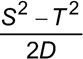
Gemäß einer Ausführungsform ermittelt der Prozessor den Zielabstand als maximale Detektionsreichweite eines oder mehrerer Sensoren des Fahrzeugs.According to one embodiment, the processor determines the target distance as the maximum detection range of one or more sensors of the vehicle.
Gemäß einer weiteren Ausführungsform bestimmt der Prozessor den Zielabstand als ein Abstand, der kleiner ist als die maximale Detektionsreichweite eines oder mehrerer Sensoren des Fahrzeugs, basierend auf dem Erfassen eines nachfolgenden Fahrzeugs hinter dem Fahrzeug.According to another embodiment, the processor determines the target distance as a distance less than the maximum detection range of one or more sensors of the vehicle based on detecting a following vehicle behind the vehicle.
Gemäß einer weiteren Ausführungsform bestimmt der Prozessor den Zielabstand basierend auf einer Position des einen oder der mehreren Sensoren des Fahrzeugs, dem Abstands zwischen dem Fahrzeug und dem nachfolgenden Fahrzeug sowie der Breite des nachfolgenden Fahrzeugs.According to another embodiment, the processor determines the target distance based on a position of the one or more sensors of the vehicle, the distance between the vehicle and the following vehicle, and the width of the following vehicle.
Gemäß einer weiteren Ausführungsform bestimmt der Prozessor die Zielgeschwindigkeit als einen festen Wert oberhalb einer angegebenen Geschwindigkeitsbeschränkung für die Zielspur.According to another embodiment, the processor determines the target speed as a fixed value above a specified speed limit for the target lane.
Gemäß einer weiteren Ausführungsform erlaubt der Prozessor den automatischen Spurwechsel basierend darauf, dass die Abbremsrate kleiner oder gleich der Schwellenabbremsrate ist.According to another embodiment, the processor allows automatic lane changing based on the deceleration rate being less than or equal to the threshold deceleration rate.
Die oben genannten Merkmale und Vorteile sowie weitere Merkmale und Vorteile der Offenbarung sind aus der folgenden detaillierten Beschreibung in Verbindung mit den beigefügten Figuren leicht ersichtlich.The above features and advantages, as well as other features and advantages of the disclosure, will be readily apparent from the following detailed description taken in conjunction with the accompanying figures.
Kurzbeschreibung der ZeichnungenBrief description of the drawings
Weitere Merkmale, Vorteile und Details erscheinen nur beispielhaft in der folgenden detaillierten Beschreibung, wobei sich die detaillierte Beschreibung auf die Figuren bezieht, in denen:
-
1 ein Blockschaltbild eines Fahrzeugs ist, das adaptive Steuerung eines automatischen Spurwechsels beinhaltet; -
2 ein Blockdiagramm ist, das das Verfahren zum Durchführen der adaptiven Steuerung eines automatischen Spurwechsels nach einer oder mehreren Ausführungsformen veranschaulicht; -
3 ein Prozessablauf eines Verfahrens zum Durchführen einer adaptiven Steuerung eines automatischen Spurwechsels nach einer oder mehreren Ausführungsformen ist; und -
4 ein exemplarisches Szenario zeigt, in dem adaptive Steuerung eines automatischen Spurwechsels nach einer oder mehreren Ausführungsformen durchgeführt wird.
-
1 is a block diagram of a vehicle incorporating adaptive control of automatic lane change; -
2 is a block diagram illustrating the method for performing adaptive control of an automatic lane change according to one or more embodiments; -
3 is a process flow of a method for performing adaptive control of an automatic lane change according to one or more embodiments; and -
4 shows an exemplary scenario in which adaptive control of an automatic lane change is performed according to one or more embodiments.
Detaillierte BeschreibungDetailed description
Die folgende Beschreibung ist lediglich beispielhafter Natur und ist nicht dazu beabsichtigt, die vorliegende Offenbarung, ihre Anwendung oder ihren Gebrauch einzuschränken. Es sollte verstanden werde, dass in den Figuren durchgehend entsprechende Bezugszeichen auf gleiche oder entsprechende Teile und Merkmale hinweisen.The following description is merely exemplary in nature and is not intended to limit the present disclosure, its application, or uses. It should be understood that throughout the figures, corresponding reference characters refer to like or corresponding parts and features.
Wie zuvor erwähnt, können automatische Spurwechselvorgänge Teil des autonomen oder teilautonomen Betriebs eines Fahrzeugs sein. Typischerweise kann ein Spurwechsel vorgenommen werden, wenn die Nachbarspur, in die das Fahrzeug einfahren wird, frei von Hindernissen ist. Das heißt, es wird die Position anderer Fahrzeuge oder beliebiger Objekte im Sichtfeld von Fahrzeugsensoren (z.B. Kameras) ermittelt. Befinden sich keine anderen Fahrzeuge oder andere Gegenstände im Weg des Spurwechsels, wird dieser vorgenommen. Allerdings kann es unter gewissen Umständen problematisch sein, nur die Objekte im Sichtfeld zu betrachten, um festzustellen, ob ein automatischer Spurwechsel durchgeführt werden kann. Zum Beispiel kann sich bei einem automatischen Spurwechsel von einer ersten Spur in eine zweite Spur ein schnell fahrendes Fahrzeug knapp außerhalb des Sichtfeldes befinden, selbst wenn nach dem Sichtfeld der Sensoren des Fahrzeugs festgestellt wird, dass sich keine Objekte in der zweiten Spur befinden. Dieses schnell fahrende Fahrzeug kann gezwungen sein, übermäßig zu bremsen (z.B. über einen festgelegten Schwellenwert hinaus), um eine Kollision aufgrund des Spurwechsels zu vermeiden. Ausführungsformen der hierin beschriebenen Systeme und Verfahren beziehen sich auf die adaptive Steuerung eines automatischen Spurwechsels in einem Fahrzeug. Die adaptive Steuerung kann einen automatischen Spurwechsel verhindern, der ansonsten durchgeführt werden würde.As previously mentioned, automatic lane changes can be part of a vehicle's autonomous or semi-autonomous operation. Typically, a lane change can be performed if the adjacent lane into which the vehicle will enter is clear of obstructions. This means that the position of other vehicles or any objects within the field of view of vehicle sensors (e.g., cameras) is determined. If no other vehicles or other objects are in the path of the lane change, the lane change will be performed. However, under certain circumstances, considering only the objects in the field of view to determine whether an automatic lane change can be performed can be problematic. For example, during an automatic lane change from a first lane to a second lane, a fast-moving vehicle may be just outside the field of view, even if the vehicle's sensors determine that there are no objects in the second lane. This fast-moving vehicle may be forced to brake excessively (e.g., beyond a specified threshold) to avoid a collision due to the lane change. Embodiments of the systems and methods described herein relate to adaptive control of an automatic lane change in a vehicle. The adaptive control may prevent an automatic lane change that would otherwise be performed.
Entsprechend einer beispielhaften Ausführungsform ist
Eine Steuerung 150 ist auch in dem Subjektfahrzeug 100 abgebildet. Die Steuerung 150 kann Rohdaten oder Informationen von einem oder mehreren Sensoren 105 erhalten, einzeln oder nach herkömmlichen Sensor-Fusionsschemata. Die Daten oder Informationen werden verwendet, um Objekte 170 im Sichtfeld der Sensoren 105 zu erkennen. Das in
Wie mit Bezug auf
Die Erkennungszone 210 ist eine Strecke, die das Zielfahrzeug 200 in einer definierten Zeitspanne (z.B. 1 Sekunde) zurücklegen wird. Diese definierte Zeitspanne wird als Erkennungszeit bezeichnet und ist die angenommene Dauer für den Fahrer des Zielfahrzeugs 200, um zu erkennen, dass das Subjektfahrzeug 100 die Spur wechselt. Die Pufferzone 230 ist ein bestimmter Abstand vom Heck des Subjektfahrzeugs 100. Der Abstand der Pufferzone 230 wird in Abhängigkeit von der Geschwindigkeit des Fahrzeugs 100 eingestellt. Zum Beispiel kann die Pufferzone in der Größenordnung von 2 Metern für eine relativ niedrige Geschwindigkeit und in der Größenordnung von 20 Metern für eine relativ hohe Geschwindigkeit des Fahrzeugs 100 sein. Die anfängliche Einstellung oder spätere Verfeinerung des Abstands der Pufferzone 230 kann auf Experimenten oder Erfahrungen beruhen.The
Die Bremszone 220 ist der verbleibende Abstand. Das heißt, die Steuerung 150 kennt, wie bereits erwähnt, die maximale Detektionsreichweite 160. So kann die Steuerung 150 die Bremszone 220 ermitteln, indem er von der maximalen Detektionsreichweite 160 die Erkennungszone 210, die sich aus der angenommenen Geschwindigkeit des Zielfahrzeugs 200 ergibt, und die Pufferzone 230 subtrahiert. Diese Bremszone 220 ist der Abstand, innerhalb dessen das Zielfahrzeug 200 seine Geschwindigkeit auf die der Steuerung 150 bekannte Geschwindigkeit des Zielfahrzeugs 100 reduzieren muss. Die Steuerung 150 ermittelt, ob die Abbremsrate, die innerhalb der Bremszone 220 auftreten muss, größer als eine Schwellenabbremsrate ist. D.h. die Steuerung 150 bestimmt, ob das Zielfahrzeug 200 zu stark bremsen muss (gemäß des vorgegebenen Schwellenwerts), um seine Geschwindigkeit an die Geschwindigkeit des Subjektfahrzeugs 100 anzugleichen bevor es die Pufferzone 230 erreicht. Wenn ja, dann bestimmt die Steuerung 150, dass der automatische Spurwechsel nicht durchgeführt werden soll.The
Im Block 320 kann das Bestimmen einer Geschwindigkeit für das Zielfahrzeug 200, wie bereits erwähnt, basierend auf der Geschwindigkeitsbegrenzung erfolgen. Zum Beispiel kann die Geschwindigkeit des Zielfahrzeugs 200 als (Geschwindigkeitsbeschränkung + Δ) angenommen werden, und Δ kann z.B. als 15 Meilen pro Stunde gewählt werden. Der Wert von Δ kann beispielsweise aufgrund von Wetterbedingungen oder anderen Faktoren angepasst werden. Im Block 330 beinhaltet der Verfahrensablauf 300 das Berechnen der von dem Zielfahrzeug 200 in der Bremszone 220 benötigten Abbremsrate. Die Länge der Bremszone 220 wird, wie oben beschrieben, durch Subtrahieren der Längen der Erkennungszone 210 und der Pufferzone 230 von der maximalen Detektionsreichweite 160 ermittelt. Das Zielfahrzeug muss von der ermittelten Geschwindigkeit des Zielfahrzeugs 200 (aus Block 320) T auf die Geschwindigkeit des Subjektfahrzeug 100 S über die Länge der Bremszone 220 D verzögern. Die Abbremsrate ist deshalb gegeben durch:
Im Block 340 wird eine Überprüfung durchgeführt, ob die mit EQ. 1 berechnete Abbremsrate größer als eine Schwellenabbremsrate ist. Die Schwellenabbremsrate kann z.B. als 0,2 g gewählt werden (g = 9,81 Meter/Sekunde2). Falls die erforderliche Abbremsrate des (hypothetischen) Zielfahrzeugs 200 in der Bremszone 220 kleiner oder gleich dem Schwellenwert ist (gemäß der Überprüfung in Block 340), dann beinhaltet der Verfahrensablauf 300 das Fortfahren mit dem automatischen Spurwechsel in Block 350. Falls stattdessen die in Block 330 ermittelte Abbremsrate den Schwellenwert (in Block 340) überschreitet, dann beinhaltet der Verfahrensablauf 300 das Verbieten des geplanten automatischen Fahrspurwechsels in Block 360.In
Faktoren, die den Abstand MD (d.h. die modifizierte maximale Detektionsreichweite 160) beeinflussen, beinhalten den Abstand zwischen dem Subjektfahrzeug 100 und dem nachfolgenden Fahrzeug 400, die Breite W des nachfolgenden Fahrzeugs 400 und die Position des einen oder der mehreren Sensoren 105 des Subjektfahrzeugs 100, die verwendet werden, um Objekten hinter dem Subjektfahrzeug 100 zu erfassen. In dem Beispielszenario wird zu Erläuterungszwecken angenommen, dass das Subjektfahrzeug 100 und das nachfolgende Fahrzeug 400 beide in der Fahrspur zentriert sind. Der Abstand von der Mitte des Subjektfahrzeugs 100, in dem sich der Sensor 105 befindet, bis zu der Ecke von Interesse des Zielfahrzeugs 200 ist also gegeben durch (L+W/2). Die Ecke von Interesse ist die linke Ecke des Zielfahrzeugs 200, wenn die Zielspur 180 links von dem Subjektfahrzeug 100 liegt, und die Ecke von Interesse ist die rechte Ecke des Zielfahrzeugs 200, wenn die Zielspur rechts von dem Subjektfahrzeug 100 liegt. Der Wert von L basiert auf der Kenntnis der Fahrbahnbreite und einer angenommenen Breite für das Zielfahrzeug 200 (z.B. kann angenommen werden, dass das Zielfahrzeug 200 in der Mitte der Zielspur 180 liegt).Factors that affect the distance MD (i.e., the modified maximum detection range 160) include the distance between the
Wie
Claims (8)


Applications Claiming Priority (2)
| Application Number | Priority Date | Filing Date | Title |
|---|---|---|---|
| US16/352,155 | 2019-03-13 | ||
| US16/352,155 US11046321B2 (en) | 2019-03-13 | 2019-03-13 | Adaptive control of automated lane change in vehicle |
Publications (2)
| Publication Number | Publication Date |
|---|---|
| DE102020103503A1 DE102020103503A1 (en) | 2020-09-17 |
| DE102020103503B4 true DE102020103503B4 (en) | 2025-04-30 |
Family
ID=72289528
Family Applications (1)
| Application Number | Title | Priority Date | Filing Date |
|---|---|---|---|
| DE102020103503.9A Active DE102020103503B4 (en) | 2019-03-13 | 2020-02-11 | ADAPTIVE CONTROL OF AUTOMATIC LANE CHANGE IN THE VEHICLE |
Country Status (3)
| Country | Link |
|---|---|
| US (1) | US11046321B2 (en) |
| CN (1) | CN111688695A (en) |
| DE (1) | DE102020103503B4 (en) |
Families Citing this family (8)
| Publication number | Priority date | Publication date | Assignee | Title |
|---|---|---|---|---|
| BR112022011400A2 (en) * | 2019-12-10 | 2022-08-30 | Nissan Motor | STEERING CONTROL METHOD AND STEERING CONTROL DEVICE |
| JP7347227B2 (en) * | 2020-01-17 | 2023-09-20 | トヨタ自動車株式会社 | Information processing device and information processing method |
| AT523289B1 (en) * | 2020-03-25 | 2021-07-15 | Avl List Gmbh | METHOD OF CONTROLLING AN AT LEAST PARTIALLY AUTONOMOUS VEHICLE |
| US12399496B2 (en) * | 2020-06-29 | 2025-08-26 | Lyft, Inc. | Detecting positioning of a sensor system associated with a vehicle |
| US11685378B2 (en) * | 2020-10-08 | 2023-06-27 | GM Global Technology Operations LLC | Extrinsic characterization of detection capability to support automated lane change |
| US11702075B2 (en) | 2021-04-30 | 2023-07-18 | Nissan North America, Inc. | System and method for proactive lane assist |
| US11753009B2 (en) * | 2021-04-30 | 2023-09-12 | Nissan North America, Inc. | Intelligent pedal lane change assist |
| CN114348001B (en) * | 2022-01-06 | 2024-04-26 | 腾讯科技(深圳)有限公司 | Traffic simulation method, device, equipment and storage medium |
Citations (2)
| Publication number | Priority date | Publication date | Assignee | Title |
|---|---|---|---|---|
| US20170174262A1 (en) * | 2015-12-21 | 2017-06-22 | Mitsubishi Jidosha Kogyo Kabushiki Kaisha | Driving support apparatus |
| US20170349173A1 (en) * | 2016-06-06 | 2017-12-07 | Honda Motor Co., Ltd. | Vehicle and lane change timing determination method |
Family Cites Families (9)
| Publication number | Priority date | Publication date | Assignee | Title |
|---|---|---|---|---|
| JP3385921B2 (en) * | 1997-07-14 | 2003-03-10 | 日産自動車株式会社 | Vehicle follow-up control system |
| JP2005271823A (en) * | 2004-03-25 | 2005-10-06 | Mitsubishi Fuso Truck & Bus Corp | Vehicular behavior control device |
| JP5195927B2 (en) * | 2009-01-19 | 2013-05-15 | トヨタ自動車株式会社 | Vehicle control device |
| DE102014200896A1 (en) * | 2014-01-20 | 2015-07-23 | Volkswagen Aktiengesellschaft | Lane change assistance for a motor vehicle |
| JP6252399B2 (en) * | 2014-08-12 | 2017-12-27 | トヨタ自動車株式会社 | Lane change support device |
| JP6597905B2 (en) * | 2016-07-25 | 2019-10-30 | 日産自動車株式会社 | Lane change support method and lane change support device |
| KR102383427B1 (en) * | 2016-12-16 | 2022-04-07 | 현대자동차주식회사 | Apparatus and method for controlling autonomous driving of vehicle |
| JP6642413B2 (en) * | 2016-12-27 | 2020-02-05 | トヨタ自動車株式会社 | Vehicle travel control device |
| CN109017792B (en) * | 2018-07-16 | 2020-08-14 | 东南大学 | Ecological driving method for vehicle lane changing behavior based on vehicle-road coordination technology |
-
2019
- 2019-03-13 US US16/352,155 patent/US11046321B2/en active Active
-
2020
- 2020-02-11 DE DE102020103503.9A patent/DE102020103503B4/en active Active
- 2020-03-10 CN CN202010160615.6A patent/CN111688695A/en active Pending
Patent Citations (2)
| Publication number | Priority date | Publication date | Assignee | Title |
|---|---|---|---|---|
| US20170174262A1 (en) * | 2015-12-21 | 2017-06-22 | Mitsubishi Jidosha Kogyo Kabushiki Kaisha | Driving support apparatus |
| US20170349173A1 (en) * | 2016-06-06 | 2017-12-07 | Honda Motor Co., Ltd. | Vehicle and lane change timing determination method |
Also Published As
| Publication number | Publication date |
|---|---|
| US11046321B2 (en) | 2021-06-29 |
| DE102020103503A1 (en) | 2020-09-17 |
| CN111688695A (en) | 2020-09-22 |
| US20200290618A1 (en) | 2020-09-17 |
Similar Documents
| Publication | Publication Date | Title |
|---|---|---|
| DE102020103503B4 (en) | ADAPTIVE CONTROL OF AUTOMATIC LANE CHANGE IN THE VEHICLE | |
| DE102013100206B4 (en) | Intersection collision avoidance with adaptable vehicle dimensions | |
| EP2097770B1 (en) | Vertical orientation of a lidar sensor | |
| EP2242674B1 (en) | Method and assistance system for detecting objects in the surrounding area of a vehicle | |
| DE102004004918B4 (en) | Method for collision warning in a motor vehicle | |
| DE102011117554B4 (en) | driving environment detection device | |
| DE102012202916B4 (en) | Method and device for operating a vehicle | |
| DE112017001351B4 (en) | DRIVING ASSISTANCE DEVICE | |
| DE102017100633B4 (en) | PREVENTION SAFETY DEVICE FOR CHANGING THE PRICE OF A SMALL VEHICLE | |
| DE102019120118A1 (en) | DEVICE AND METHOD FOR CONTROLLING THE DRIVING OF A VEHICLE | |
| DE112017005803B4 (en) | VEHICLE CONTROL DEVICE AND VEHICLE CONTROL METHOD | |
| DE102014221144A1 (en) | Target detection device | |
| DE102016011970A1 (en) | Vehicle Security System | |
| DE102009047333A1 (en) | Method for determining a trajectory of a vehicle | |
| DE102009017152A1 (en) | Method and device for longitudinal and transverse guidance of a motor vehicle | |
| DE19745231A1 (en) | Automatic anti collision warning system for road vehicles | |
| DE102012111846A1 (en) | Collision protection method for releasing warning signal and/or predetermined action for passenger car, involves determining time span in which object reaches local zone from relative speed of object and/or vehicle when path crosses zone | |
| DE102018213262A1 (en) | Method for operating a motor vehicle, in particular a motorcycle, computer program | |
| WO2020052840A1 (en) | Method and device for operating an at least semi-automatically operated first vehicle | |
| DE102016118308B4 (en) | Method for determining a distance between a motor vehicle and an object with adaptation of a number of distance values taken into account, control unit, driver assistance system and motor vehicle | |
| DE112017007636T5 (en) | Rear pre-crash safety system | |
| DE102017106952A1 (en) | DISTANCE CONTROL FOR A VEHICLE WITH TRAILER | |
| DE102013015028A1 (en) | Method for operating a vehicle | |
| DE102018117692A1 (en) | Method for performing an overtaking maneuver taking into account a safety distance, analysis component, driver assistance system and vehicle | |
| DE102020131933A1 (en) | METHOD OF OPERATING A PARKING ASSISTANCE SYSTEM, COMPUTER PROGRAM PRODUCT, PARKING ASSISTANCE SYSTEM AND VEHICLE |
Legal Events
| Date | Code | Title | Description |
|---|---|---|---|
| R012 | Request for examination validly filed | ||
| R016 | Response to examination communication | ||
| R018 | Grant decision by examination section/examining division | ||
| R020 | Patent grant now final |