DE102020102825A1 - Reinforcement element comprising filaments - Google Patents
Reinforcement element comprising filaments Download PDFInfo
- Publication number
- DE102020102825A1 DE102020102825A1 DE102020102825.3A DE102020102825A DE102020102825A1 DE 102020102825 A1 DE102020102825 A1 DE 102020102825A1 DE 102020102825 A DE102020102825 A DE 102020102825A DE 102020102825 A1 DE102020102825 A1 DE 102020102825A1
- Authority
- DE
- Germany
- Prior art keywords
- reinforcement element
- filaments
- filament bundle
- element according
- reinforcement
- Prior art date
- Legal status (The legal status is an assumption and is not a legal conclusion. Google has not performed a legal analysis and makes no representation as to the accuracy of the status listed.)
- Pending
Links
Images
Classifications
-
- E—FIXED CONSTRUCTIONS
- E04—BUILDING
- E04C—STRUCTURAL ELEMENTS; BUILDING MATERIALS
- E04C5/00—Reinforcing elements, e.g. for concrete; Auxiliary elements therefor
- E04C5/07—Reinforcing elements of material other than metal, e.g. of glass, of plastics, or not exclusively made of metal
Landscapes
- Engineering & Computer Science (AREA)
- Architecture (AREA)
- Civil Engineering (AREA)
- Structural Engineering (AREA)
- Reinforcement Elements For Buildings (AREA)
Abstract
Die Erfindung betrifft ein Filamente umfassendes, im Wesentlichen stabförmiges Bewehrungselement, wobei die Filamente zu wenigstens einem Filamentbündel (2) zusammengefasst sind, das wenigstens eine Filamentbündel (2) mit einem aushärtbaren Matrixmaterial (3) versehen und einer Formgebung unterzogen und ausgehärtet ist, dadurch gekennzeichnet, dass das wenigstens eine Filamentbündel (2) wechselweise zwischen einem Oberflächenbereich (4) und einem Innenbereich (6) des Bewehrungselements (1, 1') verläuft.The invention relates to a substantially rod-shaped reinforcement element comprising filaments, the filaments being combined into at least one filament bundle (2), the at least one filament bundle (2) being provided with a hardenable matrix material (3) and being shaped and hardened, characterized that the at least one filament bundle (2) runs alternately between a surface area (4) and an inner area (6) of the reinforcement element (1, 1 ').
Description
Die Erfindung betrifft ein Filamente umfassendes, im Wesentlichen stabförmiges Bewehrungselement, wobei die Filamente zu wenigstens einem Filamentbündel zusammengefasst sind, das wenigstens eine Filamentbündel mit einem aushärtbaren Matrixmaterial versehen und einer Formgebung unterzogen und ausgehärtet ist.The invention relates to a substantially rod-shaped reinforcement element comprising filaments, the filaments being combined to form at least one filament bundle, the at least one filament bundle being provided with a curable matrix material and being shaped and cured.
Der Baustoff Beton ist sehr gut geeignet zur Aufnahme von Druckbelastungen. Er besitzt jedoch nur ein geringes Aufnahmevermögen hinsichtlich einer Zugbeanspruchung und zeigt ein ausgeprägt sprödes Materialversagen. Daher benötigen Betonbauteile zur Aufnahme von Zugspannungen, beispielsweise resultierend aus Biegemomenten und aus Zwangsspannungen wie Schwinden oder Temperatureinfluss, eine Bewehrung. Durch die Kombination von Beton und zugkraftaufnehmender Bewehrung entsteht ein hochleistungsfähiger Baustoff. Die Bewehrung kann hierbei in verschiedenen geometrischen Anordnungen eingebaut werden und es kommen vor allem gitterförmige Strukturen und Stäbe zur Anwendung. Eine Stahlbewehrung kann im Beton rosten und zu erheblichen Bauwerksschäden führen, außerdem sind diese Bewehrungen durch die hohe Dichte von Stahl sehr schwer und unhandlich und fordern Betonüberdeckungen von bis zu 5,5 cm zum Schutz gegen Korrosion.The building material concrete is very well suited to absorbing pressure loads. However, it has only a low absorption capacity with regard to tensile stress and shows a pronounced brittle material failure. Concrete components therefore need reinforcement to absorb tensile stresses, for example resulting from bending moments and constrained stresses such as shrinkage or the influence of temperature. The combination of concrete and tensile force-absorbing reinforcement creates a high-performance building material. The reinforcement can be installed in various geometric arrangements and grid-like structures and bars are mainly used. Steel reinforcement can rust in the concrete and lead to considerable structural damage. In addition, due to the high density of steel, these reinforcements are very heavy and unwieldy and require concrete coverings of up to 5.5 cm to protect against corrosion.
Zur Reduzierung der erforderlichen Betonüberdeckungen ist der Einsatz korrosionsunempfindlicher Materialien wie Carbon oder alkaliresistenten Glases bekannt, beispielsweise ausgeführt als textile Flächengebilde (Gelege) oder stabförmige Bewehrungselemente. Diese bestehen zumeist aus Multifilamentgarnen auf Grundlage der Materialien Glas (insbesondere alkaliresistent), Carbon oder Basalt. Diese einzelnen Multifilamentgarne (Roving) bestehen wiederum aus mehreren tausend Filamenten mit einem Durchmesser von ca. 5 bis 8 µm (bei Carbon). Würden die Rovings unbeschichtet in den Beton eingelegt, würden sich lediglich die äußeren Filamente der Rovings mit dem Beton verbinden und die inneren Filamente des Rovings keine Verbindung zum Beton haben. Daher würden sich somit in erster Linie auch nur die äußeren Filamente an der Lastabtragung beteiligen.To reduce the required concrete cover, the use of corrosion-resistant materials such as carbon or alkali-resistant glass is known, for example in the form of flat textile structures (scrims) or rod-shaped reinforcement elements. These mostly consist of multifilament yarns based on the materials glass (especially alkali-resistant), carbon or basalt. These individual multifilament yarns (rovings) in turn consist of several thousand filaments with a diameter of approx. 5 to 8 µm (for carbon). If the rovings were inserted into the concrete uncoated, only the outer filaments of the rovings would connect to the concrete and the inner filaments of the roving would have no connection to the concrete. Therefore, primarily only the outer filaments would take part in the load transfer.
Zur weitgehenden Beteiligung aller Filamente am Lastabtrag wird der Roving bzw. das Textil mit einer Beschichtung versehen bzw. in eine Matrix eingebettet, die in die Struktur infiltriert. Dies sind meist Kunststoffe, wie beispielsweise Stryrolbutadien oder Epoxidharz. Durch diese Beschichtung werden zunächst alle Filamente eines Rovings miteinander verbunden. Dieser kompakte Roving ähnelt einem faserverstärkten Kunststoff. Wenn dieser Roving in den Beton eingelegt wird, verbindet sich der Beton wiederum nur mit den äußeren Filamenten. Der Kunststoff stellt aber sicher, dass sich ein Großteil der Filamente am Lastabtrag beteiligt. Die Tragfähigkeit der beschichteten Strukturen ist damit deutlich höher als die der unbeschichteten Rovings, hängt aber von der dauerhaften Belastbarkeit der Matrix ab.The roving or textile is provided with a coating or embedded in a matrix, which infiltrates into the structure, so that all filaments participate to a large extent in the load transfer. These are mostly plastics such as styrene butadiene or epoxy resin. This coating initially connects all the filaments of a roving to one another. This compact roving is similar to a fiber-reinforced plastic. When this roving is inserted into the concrete, the concrete, in turn, only bonds to the outer filaments. However, the plastic ensures that a large part of the filaments take part in the load transfer. The load-bearing capacity of the coated structures is thus significantly higher than that of the uncoated rovings, but depends on the permanent load-bearing capacity of the matrix.
Filamente umfassende Bewehrungselemente mit profilierter Oberfläche, insbesondere Bewehrungsstäbe, sind aus dem Stand der Technik bekannt. So sind aus den Druckschriften
Aus der Druckschrift
Die Druckschrift
Weitere Lösungen für ein Bewehrungselement mit einer verbesserten Oberflächenstruktur sind den Druckschriften
Es ist daher Aufgabe der vorliegenden Erfindung, ein oberflächennahe und innenliegende Filamente umfassendes Bewehrungselement anzubieten, bei dem ein unmittelbarer Lastabtrag über die Oberfläche, jedoch nicht nur durch die oberflächennahen Filamente erfolgt.It is therefore the object of the present invention to offer a reinforcement element which is close to the surface and includes filaments on the inside, in which a direct load transfer takes place via the surface, but not only by the filaments close to the surface.
Die Aufgabe wird gelöst durch ein Filamente umfassendes, im Wesentlichen stabförmiges Bewehrungselement, wobei die Filamente zu wenigstens einem Filamentbündel zusammengefasst sind, das wenigstens eine Filamentbündel mit einem aushärtbaren Matrixmaterial versehen und einer Formgebung unterzogen und ausgehärtet ist. Nach der Erfindung verläuft das wenigstens eine Filamentbündel vor dem Aushärten wechselweise zwischen einem Oberflächenbereich und einem Innenbereich des Bewehrungselements. Dies wird nachfolgend auch als Positions-Variation der Einzelstränge bezeichnet.The object is achieved by an essentially rod-shaped reinforcement element comprising filaments, the filaments being combined into at least one filament bundle, the at least one filament bundle being provided with a curable matrix material and being shaped and cured. According to the invention, the at least one filament bundle runs alternately between a surface area and an inner area of the reinforcement element before curing. This is also referred to below as the position variation of the individual strands.
Das Bewehrungselement ist insbesondere zum Einbau in ein Betonbauteil vorgesehen, kann aber auch zur Bewehrung anderer Bauelement mit anderen Materialien der Bauteilmatrix als Beton verwendet werden. Es ist bevorzugt ausgeführt als ein Bewehrungsstab.The reinforcement element is intended in particular for installation in a concrete component, but can also be used to reinforce other components with materials of the component matrix other than concrete. It is preferably designed as a reinforcing bar.
Die Filamente können aus Carbon, Glas oder Basalt bestehen. Dies sind die am häufigsten verwendeten Fasern im Baubereich, da sie sich resistent gegenüber der alkalischen Umgebung in einem Betonbauteil erweisen oder entsprechend ausgebildet sind.The filaments can be made of carbon, glass or basalt. These are the most frequently used fibers in the construction sector, as they prove to be resistant to the alkaline environment in a concrete component or are designed accordingly.
Es hat sich als vorteilhaft erwiesen, wenn das wenigstens eine Filamentbündel zwischen dem Oberflächenbereich und dem Innenbereich des Bewehrungselements in der Weise geführt ist, dass bei Betrachtung im Querschnitt um einen Kern herum Bereiche ausgebildet werden, die von diesem teilweise isoliert sind. Die isolierten Bereiche sind nur teilweise mit dem Kern verbunden, nämlich über die zwischen Kern und isolierten Bereichen verlaufende Filamentbündel, und teilweise isoliert von diesem. Durch die isolierten Bereiche kann eine besonders gute Verankerung und damit eine optimale Kraftübertragung zwischen dem Material der Bauteilmatrix, insbesondere dem Beton eines Betonbauteils, gewährleistet werden. Der Beton oder eine andere Bauteilmatrix kann zwischen den Kern und die isolierten Bereiche fließen.It has proven to be advantageous if the at least one filament bundle is guided between the surface area and the inner area of the reinforcement element in such a way that, when viewed in cross section, areas are formed around a core which are partially isolated from it. The isolated areas are only partially connected to the core, namely via the filament bundles running between the core and isolated areas, and are partially isolated from it. The isolated areas ensure particularly good anchoring and thus optimal force transmission between the material of the component matrix, in particular the concrete of a concrete component. The concrete or other component matrix can flow between the core and the isolated areas.
Es hat sich weiterhin als vorteilhaft erweisen, wenn das wenigstens eine Filamentbündel zwischen dem Oberflächenbereich und dem Innenbereich des Bewehrungselements in der Weise geführt ist, dass ein Querschnitt in der Form eines Fraktals ausgebildet wird, weil das Verhältnis aus Umfang zu Querschnittsfläche im Fraktal sehr groß ist. Dies führt durch die große Fläche, die für eine Verbindung mit der Bauteilmatrix zur Verfügung steht, zu hoher Materialeffizienz.It has also proven to be advantageous if the at least one filament bundle is guided between the surface area and the inner area of the reinforcement element in such a way that a cross-section is formed in the shape of a fractal, because the ratio of circumference to cross-sectional area in the fractal is very large . Due to the large area available for connection to the component matrix, this leads to high material efficiency.
Vorteilhafterweise ist ein Ende des Bewehrungselements in der Weise gespreizt oder flachgedrückt ausgeführt, dass nach dem Einsetzen in eine entsprechende Ausnehmung eines Bauelements, die sich beispielsweise nach außen hin schwalbenschwanzartig verjüngt, eine Keilwirkung entsteht. Das Bewehrungselement wird in der Ausnehmung formschlüssig mit dem Bauelement verbunden. Dadurch kann die Verankerung mit einem bestehenden Bauteil erheblich verbessert und die bei Carbonfasern oder anderen nichtmetallischen Bewehrungsmaterialien üblicherweise große Verankerungslänge reduziert werden.Advantageously, one end of the reinforcement element is spread or flattened in such a way that a wedge effect is created after insertion into a corresponding recess of a component, which tapers outwardly, for example, like a dovetail. The reinforcement element is positively connected to the component in the recess. As a result, the anchoring with an existing component can be significantly improved and the anchoring length, which is usually long with carbon fibers or other non-metallic reinforcement materials, can be reduced.
Erfindungsgemäß wird das wenigstens eine Filamentbündel vor dem Aushärten wechselweise zwischen einem Oberflächenbereich und einem Innenbereich des Bewehrungselements mittels eines bekannten Verfahrens aus der Textiltechnik, wie z. B. durch eine Verflechtung, geführt. Dadurch erhält es den Verlauf, der die erfindungsgemäßen Vorteile mit sich bringt.According to the invention, the at least one filament bundle is alternately between a surface area and an inner area of the reinforcement element by means of a known method from textile technology, such as. B. by an interweaving. This gives it the course that brings the advantages according to the invention with it.
Durch die Ausbildung einer großen Oberfläche, eine Oberflächenprofilierung oder eine Oberflächenbearbeitung werden die Oberfläche und der Umfang des Stabes im Verankerungsbereich erhöht. Dadurch kann ein besserer Verbund sichergestellt werden, da sich eine größere Oberfläche am Lastabtrag beteiligt. Durch die erfindungsgemäße Positions-Variation der Einzelstränge, deren Wechsel zwischen dem Innenbereich und dem Oberflächenbereich, wird der Querschnitt gleichmäßiger beansprucht.By forming a large surface, surface profiling or surface treatment, the surface and the circumference of the rod in the anchoring area are increased. In this way, a better bond can be ensured, since a larger surface contributes to the load transfer. Due to the position variation according to the invention of the individual strands, their alternation between the inner area and the surface area, the cross-section is stressed more evenly.
Die vorliegende Erfindung überwindet Nachteile von Bewehrungselementen ohne Profilierung. Bei diesen werden lange Verankerungslängen benötigt, was zur Verbindung mit bestehenden Bauteilen tiefe Bohrlöcher erfordert. Dies führt wiederum zu hohen Querdrücken und einer Spannungskonzentration am Lasteinleitungsbeginn. Die Bereiche werden unterschiedlich belastet und nur ein oberflächennaher Teil des Bewehrungsstabes wird beansprucht. Dies kann bei einer profilierten Oberfläche zum Abscheren von Rippen führen. Die resultierende Belastung ist teilweise nicht materialgerecht, vor allem wegen der hohen Querdruckempfindlichkeit von CFK (Carbonfaser verstärkter Kunststoff).The present invention overcomes disadvantages of reinforcement elements without profiling. Long anchoring lengths are required for these, which requires deep drill holes to connect to existing components. This in turn leads to high transverse pressures and a concentration of stress at the beginning of the load application. The areas are stressed differently and only a part of the reinforcing bar near the surface is stressed. In the case of a profiled surface, this can lead to the shearing of ribs. The resulting load is in some cases not appropriate for the material, mainly because of the high sensitivity to lateral pressure of CFRP (carbon fiber reinforced plastic).
Demgegenüber bietet die vorliegende Erfindung Vorteile, indem eine zuverlässige Verankerung durch größere Verbundoberfläche des Bewehrungsstabes gesichert wird. Sie führt zu einem besseren Verbund zwischen der erfindungsgemäßen nichtmetallischen bzw. filamentbasierten Bewehrung und der Bauteilmatrix des späteren Bauteils, insbesondere dem Beton des Betonbauteils. Eine gleichmäßige Spannungsverteilung im Querschnitt durch Filamentbündel, beispielsweise CFK-Stränge, welche ihre Position im Querschnitt variieren, wird erreicht. Die Einzelstränge verlaufen dazu vom äußeren Bereich in den inneren Bereich und wieder zurück in den äußeren Bereich. Dies hat zur Folge, dass der Querschnitt sich gleichmäßig am Lastabtrag beteiligt und keine lokalen Spitzen, z. B. im Randbereich, auftreten. In contrast, the present invention offers advantages in that reliable anchoring is ensured by the larger composite surface of the reinforcing bar. It leads to a better bond between the non-metallic or filament-based reinforcement according to the invention and the component matrix of the later component, in particular the concrete of the concrete component. A uniform distribution of stress in the cross-section through filament bundles, for example CFRP strands, which vary their position in the cross-section, is achieved. The individual strands run from the outer area to the inner area and back again to the outer area. As a result, the cross-section is evenly involved in the load transfer and no local peaks, e.g. B. in the edge area occur.
Hieraus resultieren geringere erforderliche Verankerungslängen im Beton und eine bessere Ausnutzung des Materials wird ermöglicht, was zur Ressourceneffizienz beiträgt. Weiterhin resultieren eine bessere Spannungsverteilung entlang der Verankerungslänge und ein besserer Verbund zwischen nichtmetallischer und der Bauteilmatrix, in die die Bewehrung eingebettet wird.This results in shorter anchoring lengths required in the concrete and a better utilization of the material is made possible, which contributes to resource efficiency. Furthermore, the result is a better stress distribution along the anchoring length and a better bond between the non-metallic and the component matrix in which the reinforcement is embedded.
Anhand der Beschreibung von Ausführungsbeispielen und ihrer Darstellung in den zugehörigen Zeichnungen wird die Erfindung nachfolgend näher erläutert.The invention is explained in more detail below on the basis of the description of exemplary embodiments and their representation in the associated drawings.
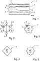
Die Filamentbündel
Durch die isolierten Bereiche
Eine andere Querschnittsform einer weiteren Ausführungsform eines erfindungsgemäßen Bewehrungselements
In einem Bereich B sind die Filamentbündel
Die
BezugszeichenlisteList of reference symbols
- 1,1'1.1 '
- BewehrungselementReinforcement element
- 22
- FilamentbündelBundles of filaments
- 33
- MatrixmaterialMatrix material
- 44th
- OberflächenbereichSurface area
- 66th
- InnenbereichIndoor
- 88th
- Kerncore
- 1010
- isolierter Bereichisolated area
ZITATE ENTHALTEN IN DER BESCHREIBUNGQUOTES INCLUDED IN THE DESCRIPTION
Diese Liste der vom Anmelder aufgeführten Dokumente wurde automatisiert erzeugt und ist ausschließlich zur besseren Information des Lesers aufgenommen. Die Liste ist nicht Bestandteil der deutschen Patent- bzw. Gebrauchsmusteranmeldung. Das DPMA übernimmt keinerlei Haftung für etwaige Fehler oder Auslassungen.This list of the documents listed by the applicant was generated automatically and is included solely for the better information of the reader. The list is not part of the German patent or utility model application. The DPMA assumes no liability for any errors or omissions.
Zitierte PatentliteraturPatent literature cited
- EP 1250499 A1 [0005]EP 1250499 A1 [0005]
- DE 102015100386 A1 [0005]DE 102015100386 A1 [0005]
- DE 10121102 A1 [0006]DE 10121102 A1 [0006]
- US 2013/0239503 A1 [0006]US 2013/0239503 A1 [0006]
- EP 2438251 B1 [0006]EP 2438251 B1 [0006]
- DE 10108357 A1 [0007]DE 10108357 A1 [0007]
- US 5725954 A [0007]US 5725954 A [0007]
- DE 102017107948 A1 [0008]DE 102017107948 A1 [0008]
- DE 102016111176 A1 [0008]DE 102016111176 A1 [0008]
Claims (8)
Priority Applications (1)
| Application Number | Priority Date | Filing Date | Title |
|---|---|---|---|
| DE102020102825.3A DE102020102825A1 (en) | 2020-02-04 | 2020-02-04 | Reinforcement element comprising filaments |
Applications Claiming Priority (1)
| Application Number | Priority Date | Filing Date | Title |
|---|---|---|---|
| DE102020102825.3A DE102020102825A1 (en) | 2020-02-04 | 2020-02-04 | Reinforcement element comprising filaments |
Publications (1)
| Publication Number | Publication Date |
|---|---|
| DE102020102825A1 true DE102020102825A1 (en) | 2021-08-05 |
Family
ID=76853963
Family Applications (1)
| Application Number | Title | Priority Date | Filing Date |
|---|---|---|---|
| DE102020102825.3A Pending DE102020102825A1 (en) | 2020-02-04 | 2020-02-04 | Reinforcement element comprising filaments |
Country Status (1)
| Country | Link |
|---|---|
| DE (1) | DE102020102825A1 (en) |
Citations (13)
| Publication number | Priority date | Publication date | Assignee | Title |
|---|---|---|---|---|
| GB2278902A (en) | 1993-06-08 | 1994-12-14 | Millfield Enterprises Limited | End-fixing apparatus |
| US5725954A (en) | 1995-09-14 | 1998-03-10 | Montsinger; Lawrence V. | Fiber reinforced thermoplastic composite with helical fluted surface and method of producing same |
| DE10108357A1 (en) | 2001-02-21 | 2002-08-29 | Sika Ag, Vorm. Kaspar Winkler & Co | Reinforcing bar and method for its production |
| EP1250499A1 (en) | 2000-01-13 | 2002-10-23 | The Dow Chemical Company | Reinforcing bars for concrete structures |
| DE10121102A1 (en) | 2001-04-27 | 2002-11-07 | Bayer Ag | triazolopyrimidines |
| US20080028740A1 (en) | 2004-10-19 | 2008-02-07 | Kenichi Ushijima | Cable Made Of High Strength Fiber Composite Material |
| RU2482247C2 (en) | 2011-05-26 | 2013-05-20 | Христофор Авдеевич Джантимиров | Method to manufacture non-metal reinforcement element with periodic surface and reinforcement element with periodic surface |
| US20130239503A1 (en) | 2010-10-21 | 2013-09-19 | Reforcetech Ltd. | Reinforcement bar and method for manufacturing same |
| DE102015100386A1 (en) | 2015-01-13 | 2016-07-14 | Technische Universität Dresden | Reinforcing rod of filament composite and method for its production |
| EP2438251B1 (en) | 2009-06-02 | 2016-09-28 | Solerial Matusions AB | Composite reinforcement |
| DE102016111176A1 (en) | 2015-06-18 | 2016-12-22 | V. Fraas Gmbh | Concrete reinforcement grid element, process for its production and its use |
| DE102017107948A1 (en) | 2017-04-12 | 2018-10-18 | Technische Universität Dresden | Reinforcing bar for insertion into a concrete matrix and its production method, a reinforcement system consisting of several reinforcing bars and a concrete component |
| EP3006611B1 (en) | 2013-06-05 | 2019-02-20 | KOMATSU MATERE Co., Ltd. | Strand structure, and multi-strand structure |
-
2020
- 2020-02-04 DE DE102020102825.3A patent/DE102020102825A1/en active Pending
Patent Citations (13)
| Publication number | Priority date | Publication date | Assignee | Title |
|---|---|---|---|---|
| GB2278902A (en) | 1993-06-08 | 1994-12-14 | Millfield Enterprises Limited | End-fixing apparatus |
| US5725954A (en) | 1995-09-14 | 1998-03-10 | Montsinger; Lawrence V. | Fiber reinforced thermoplastic composite with helical fluted surface and method of producing same |
| EP1250499A1 (en) | 2000-01-13 | 2002-10-23 | The Dow Chemical Company | Reinforcing bars for concrete structures |
| DE10108357A1 (en) | 2001-02-21 | 2002-08-29 | Sika Ag, Vorm. Kaspar Winkler & Co | Reinforcing bar and method for its production |
| DE10121102A1 (en) | 2001-04-27 | 2002-11-07 | Bayer Ag | triazolopyrimidines |
| US20080028740A1 (en) | 2004-10-19 | 2008-02-07 | Kenichi Ushijima | Cable Made Of High Strength Fiber Composite Material |
| EP2438251B1 (en) | 2009-06-02 | 2016-09-28 | Solerial Matusions AB | Composite reinforcement |
| US20130239503A1 (en) | 2010-10-21 | 2013-09-19 | Reforcetech Ltd. | Reinforcement bar and method for manufacturing same |
| RU2482247C2 (en) | 2011-05-26 | 2013-05-20 | Христофор Авдеевич Джантимиров | Method to manufacture non-metal reinforcement element with periodic surface and reinforcement element with periodic surface |
| EP3006611B1 (en) | 2013-06-05 | 2019-02-20 | KOMATSU MATERE Co., Ltd. | Strand structure, and multi-strand structure |
| DE102015100386A1 (en) | 2015-01-13 | 2016-07-14 | Technische Universität Dresden | Reinforcing rod of filament composite and method for its production |
| DE102016111176A1 (en) | 2015-06-18 | 2016-12-22 | V. Fraas Gmbh | Concrete reinforcement grid element, process for its production and its use |
| DE102017107948A1 (en) | 2017-04-12 | 2018-10-18 | Technische Universität Dresden | Reinforcing bar for insertion into a concrete matrix and its production method, a reinforcement system consisting of several reinforcing bars and a concrete component |
Non-Patent Citations (1)
| Title |
|---|
| RU 2 482 247 C2 – Maschinenübersetzung [ online abgerufen am 15.12.2020 über Google Patents ] |
Similar Documents
| Publication | Publication Date | Title |
|---|---|---|
| EP2475817B1 (en) | Rope comprising carbon filaments | |
| EP0710313B1 (en) | Anchorage device for high-performance fiber composite cables | |
| DE69008803T2 (en) | Fiber reinforced construction rod made of synthetic resin. | |
| EP3245349B1 (en) | Reinforcing bar of filament composite and method for producing same | |
| EP1364094A1 (en) | Reinforcing bar and method for the production thereof | |
| DE3319296C2 (en) | Block or plate made of impregnated graphite / fiber composite material and manufacturing process therefor | |
| EP2154401A2 (en) | Reinforced plastic fibre pipe | |
| DE2361181C2 (en) | Flexible line or cable with tensile reinforcement | |
| EP0363779A1 (en) | Anchoring device for a tensioning rod composed of a fibre composite | |
| DE102016210040A1 (en) | A method for producing an at least partially profiled, fiber-reinforced plastic profile, a profiled, fiber-reinforced plastic profile and its use | |
| EP3568288A1 (en) | Strand profile and method for producing a strand profile | |
| DE102019126609A1 (en) | Tubular reinforcement element, process for its production, use, global reinforcement, printer description file and concrete component | |
| DE102017102366A1 (en) | End anchorage of textile fabrics | |
| EP1606448B1 (en) | Method for producing a cable | |
| DE102019129581A1 (en) | Spiral spring element made from a fiber plastic composite material | |
| DE102016111176A1 (en) | Concrete reinforcement grid element, process for its production and its use | |
| EP3318689A1 (en) | Reinforcement grid element, structure having such a reinforcement grid element and method for producing a reinforcement grid element | |
| WO2019224038A1 (en) | Reinforcing rod having an alkali resistant jacket | |
| DE102020102825A1 (en) | Reinforcement element comprising filaments | |
| DE102016211176B4 (en) | Method and use of a device for carrying out the method for the production of concrete components | |
| EP3705657B1 (en) | Textile reinforcing structure for a component, method for producing a reinforcing structure, component and semi-finished part | |
| DE102010032915A1 (en) | Plastic strand for forming rope for concrete used as building material, has several radial projections which are formed and spaced apart from each other, and glass fibers provided through radial projections | |
| EP3610092B1 (en) | Reinforcing rod for insertion in a concrete matrix and production method therefor, a reinforcement system made from a plurality of reinforcing rods, and a concrete component | |
| DE102019105493A1 (en) | Textile reinforcement structure for a component, manufacturing process for a reinforcement structure, component and semi-finished part | |
| DE102014105795A1 (en) | Textile fabric |
Legal Events
| Date | Code | Title | Description |
|---|---|---|---|
| R012 | Request for examination validly filed | ||
| R016 | Response to examination communication | ||
| R016 | Response to examination communication |