DE102019213424A1 - Accumulator arrangement - Google Patents
Accumulator arrangement Download PDFInfo
- Publication number
- DE102019213424A1 DE102019213424A1 DE102019213424.6A DE102019213424A DE102019213424A1 DE 102019213424 A1 DE102019213424 A1 DE 102019213424A1 DE 102019213424 A DE102019213424 A DE 102019213424A DE 102019213424 A1 DE102019213424 A1 DE 102019213424A1
- Authority
- DE
- Germany
- Prior art keywords
- fluid guide
- guide element
- battery
- central fluid
- accumulator arrangement
- Prior art date
- Legal status (The legal status is an assumption and is not a legal conclusion. Google has not performed a legal analysis and makes no representation as to the accuracy of the status listed.)
- Pending
Links
- 239000012530 fluid Substances 0.000 claims abstract description 119
- 239000012809 cooling fluid Substances 0.000 claims abstract description 45
- 238000001816 cooling Methods 0.000 claims abstract description 30
- 239000000853 adhesive Substances 0.000 claims description 3
- 230000001070 adhesive effect Effects 0.000 claims description 3
- 239000000463 material Substances 0.000 claims description 2
- 239000002826 coolant Substances 0.000 description 7
- 238000010276 construction Methods 0.000 description 5
- 239000007788 liquid Substances 0.000 description 3
- 239000000110 cooling liquid Substances 0.000 description 2
- 238000001746 injection moulding Methods 0.000 description 2
- 238000000034 method Methods 0.000 description 2
- BUHVIAUBTBOHAG-FOYDDCNASA-N (2r,3r,4s,5r)-2-[6-[[2-(3,5-dimethoxyphenyl)-2-(2-methylphenyl)ethyl]amino]purin-9-yl]-5-(hydroxymethyl)oxolane-3,4-diol Chemical compound COC1=CC(OC)=CC(C(CNC=2C=3N=CN(C=3N=CN=2)[C@H]2[C@@H]([C@H](O)[C@@H](CO)O2)O)C=2C(=CC=CC=2)C)=C1 BUHVIAUBTBOHAG-FOYDDCNASA-N 0.000 description 1
- 230000001419 dependent effect Effects 0.000 description 1
- 230000004941 influx Effects 0.000 description 1
- 238000004519 manufacturing process Methods 0.000 description 1
- 238000007789 sealing Methods 0.000 description 1
Images



Classifications
-
- H—ELECTRICITY
- H01—ELECTRIC ELEMENTS
- H01M—PROCESSES OR MEANS, e.g. BATTERIES, FOR THE DIRECT CONVERSION OF CHEMICAL ENERGY INTO ELECTRICAL ENERGY
- H01M10/00—Secondary cells; Manufacture thereof
- H01M10/60—Heating or cooling; Temperature control
- H01M10/62—Heating or cooling; Temperature control specially adapted for specific applications
- H01M10/625—Vehicles
-
- B—PERFORMING OPERATIONS; TRANSPORTING
- B60—VEHICLES IN GENERAL
- B60L—PROPULSION OF ELECTRICALLY-PROPELLED VEHICLES; SUPPLYING ELECTRIC POWER FOR AUXILIARY EQUIPMENT OF ELECTRICALLY-PROPELLED VEHICLES; ELECTRODYNAMIC BRAKE SYSTEMS FOR VEHICLES IN GENERAL; MAGNETIC SUSPENSION OR LEVITATION FOR VEHICLES; MONITORING OPERATING VARIABLES OF ELECTRICALLY-PROPELLED VEHICLES; ELECTRIC SAFETY DEVICES FOR ELECTRICALLY-PROPELLED VEHICLES
- B60L58/00—Methods or circuit arrangements for monitoring or controlling batteries or fuel cells, specially adapted for electric vehicles
- B60L58/10—Methods or circuit arrangements for monitoring or controlling batteries or fuel cells, specially adapted for electric vehicles for monitoring or controlling batteries
- B60L58/24—Methods or circuit arrangements for monitoring or controlling batteries or fuel cells, specially adapted for electric vehicles for monitoring or controlling batteries for controlling the temperature of batteries
- B60L58/26—Methods or circuit arrangements for monitoring or controlling batteries or fuel cells, specially adapted for electric vehicles for monitoring or controlling batteries for controlling the temperature of batteries by cooling
-
- B—PERFORMING OPERATIONS; TRANSPORTING
- B60—VEHICLES IN GENERAL
- B60L—PROPULSION OF ELECTRICALLY-PROPELLED VEHICLES; SUPPLYING ELECTRIC POWER FOR AUXILIARY EQUIPMENT OF ELECTRICALLY-PROPELLED VEHICLES; ELECTRODYNAMIC BRAKE SYSTEMS FOR VEHICLES IN GENERAL; MAGNETIC SUSPENSION OR LEVITATION FOR VEHICLES; MONITORING OPERATING VARIABLES OF ELECTRICALLY-PROPELLED VEHICLES; ELECTRIC SAFETY DEVICES FOR ELECTRICALLY-PROPELLED VEHICLES
- B60L50/00—Electric propulsion with power supplied within the vehicle
- B60L50/50—Electric propulsion with power supplied within the vehicle using propulsion power supplied by batteries or fuel cells
- B60L50/60—Electric propulsion with power supplied within the vehicle using propulsion power supplied by batteries or fuel cells using power supplied by batteries
- B60L50/64—Constructional details of batteries specially adapted for electric vehicles
-
- B—PERFORMING OPERATIONS; TRANSPORTING
- B60—VEHICLES IN GENERAL
- B60L—PROPULSION OF ELECTRICALLY-PROPELLED VEHICLES; SUPPLYING ELECTRIC POWER FOR AUXILIARY EQUIPMENT OF ELECTRICALLY-PROPELLED VEHICLES; ELECTRODYNAMIC BRAKE SYSTEMS FOR VEHICLES IN GENERAL; MAGNETIC SUSPENSION OR LEVITATION FOR VEHICLES; MONITORING OPERATING VARIABLES OF ELECTRICALLY-PROPELLED VEHICLES; ELECTRIC SAFETY DEVICES FOR ELECTRICALLY-PROPELLED VEHICLES
- B60L50/00—Electric propulsion with power supplied within the vehicle
- B60L50/50—Electric propulsion with power supplied within the vehicle using propulsion power supplied by batteries or fuel cells
- B60L50/60—Electric propulsion with power supplied within the vehicle using propulsion power supplied by batteries or fuel cells using power supplied by batteries
- B60L50/66—Arrangements of batteries
-
- B—PERFORMING OPERATIONS; TRANSPORTING
- B60—VEHICLES IN GENERAL
- B60L—PROPULSION OF ELECTRICALLY-PROPELLED VEHICLES; SUPPLYING ELECTRIC POWER FOR AUXILIARY EQUIPMENT OF ELECTRICALLY-PROPELLED VEHICLES; ELECTRODYNAMIC BRAKE SYSTEMS FOR VEHICLES IN GENERAL; MAGNETIC SUSPENSION OR LEVITATION FOR VEHICLES; MONITORING OPERATING VARIABLES OF ELECTRICALLY-PROPELLED VEHICLES; ELECTRIC SAFETY DEVICES FOR ELECTRICALLY-PROPELLED VEHICLES
- B60L58/00—Methods or circuit arrangements for monitoring or controlling batteries or fuel cells, specially adapted for electric vehicles
- B60L58/10—Methods or circuit arrangements for monitoring or controlling batteries or fuel cells, specially adapted for electric vehicles for monitoring or controlling batteries
- B60L58/18—Methods or circuit arrangements for monitoring or controlling batteries or fuel cells, specially adapted for electric vehicles for monitoring or controlling batteries of two or more battery modules
- B60L58/21—Methods or circuit arrangements for monitoring or controlling batteries or fuel cells, specially adapted for electric vehicles for monitoring or controlling batteries of two or more battery modules having the same nominal voltage
-
- H—ELECTRICITY
- H01—ELECTRIC ELEMENTS
- H01M—PROCESSES OR MEANS, e.g. BATTERIES, FOR THE DIRECT CONVERSION OF CHEMICAL ENERGY INTO ELECTRICAL ENERGY
- H01M10/00—Secondary cells; Manufacture thereof
- H01M10/60—Heating or cooling; Temperature control
- H01M10/61—Types of temperature control
- H01M10/613—Cooling or keeping cold
-
- H—ELECTRICITY
- H01—ELECTRIC ELEMENTS
- H01M—PROCESSES OR MEANS, e.g. BATTERIES, FOR THE DIRECT CONVERSION OF CHEMICAL ENERGY INTO ELECTRICAL ENERGY
- H01M10/00—Secondary cells; Manufacture thereof
- H01M10/60—Heating or cooling; Temperature control
- H01M10/61—Types of temperature control
- H01M10/617—Types of temperature control for achieving uniformity or desired distribution of temperature
-
- H—ELECTRICITY
- H01—ELECTRIC ELEMENTS
- H01M—PROCESSES OR MEANS, e.g. BATTERIES, FOR THE DIRECT CONVERSION OF CHEMICAL ENERGY INTO ELECTRICAL ENERGY
- H01M10/00—Secondary cells; Manufacture thereof
- H01M10/60—Heating or cooling; Temperature control
- H01M10/65—Means for temperature control structurally associated with the cells
- H01M10/655—Solid structures for heat exchange or heat conduction
- H01M10/6556—Solid parts with flow channel passages or pipes for heat exchange
- H01M10/6557—Solid parts with flow channel passages or pipes for heat exchange arranged between the cells
-
- H—ELECTRICITY
- H01—ELECTRIC ELEMENTS
- H01M—PROCESSES OR MEANS, e.g. BATTERIES, FOR THE DIRECT CONVERSION OF CHEMICAL ENERGY INTO ELECTRICAL ENERGY
- H01M10/00—Secondary cells; Manufacture thereof
- H01M10/60—Heating or cooling; Temperature control
- H01M10/65—Means for temperature control structurally associated with the cells
- H01M10/656—Means for temperature control structurally associated with the cells characterised by the type of heat-exchange fluid
- H01M10/6567—Liquids
- H01M10/6568—Liquids characterised by flow circuits, e.g. loops, located externally to the cells or cell casings
-
- H—ELECTRICITY
- H01—ELECTRIC ELEMENTS
- H01M—PROCESSES OR MEANS, e.g. BATTERIES, FOR THE DIRECT CONVERSION OF CHEMICAL ENERGY INTO ELECTRICAL ENERGY
- H01M50/00—Constructional details or processes of manufacture of the non-active parts of electrochemical cells other than fuel cells, e.g. hybrid cells
- H01M50/20—Mountings; Secondary casings or frames; Racks, modules or packs; Suspension devices; Shock absorbers; Transport or carrying devices; Holders
-
- H—ELECTRICITY
- H01—ELECTRIC ELEMENTS
- H01M—PROCESSES OR MEANS, e.g. BATTERIES, FOR THE DIRECT CONVERSION OF CHEMICAL ENERGY INTO ELECTRICAL ENERGY
- H01M2220/00—Batteries for particular applications
- H01M2220/20—Batteries in motive systems, e.g. vehicle, ship, plane
-
- Y—GENERAL TAGGING OF NEW TECHNOLOGICAL DEVELOPMENTS; GENERAL TAGGING OF CROSS-SECTIONAL TECHNOLOGIES SPANNING OVER SEVERAL SECTIONS OF THE IPC; TECHNICAL SUBJECTS COVERED BY FORMER USPC CROSS-REFERENCE ART COLLECTIONS [XRACs] AND DIGESTS
- Y02—TECHNOLOGIES OR APPLICATIONS FOR MITIGATION OR ADAPTATION AGAINST CLIMATE CHANGE
- Y02E—REDUCTION OF GREENHOUSE GAS [GHG] EMISSIONS, RELATED TO ENERGY GENERATION, TRANSMISSION OR DISTRIBUTION
- Y02E60/00—Enabling technologies; Technologies with a potential or indirect contribution to GHG emissions mitigation
- Y02E60/10—Energy storage using batteries
-
- Y—GENERAL TAGGING OF NEW TECHNOLOGICAL DEVELOPMENTS; GENERAL TAGGING OF CROSS-SECTIONAL TECHNOLOGIES SPANNING OVER SEVERAL SECTIONS OF THE IPC; TECHNICAL SUBJECTS COVERED BY FORMER USPC CROSS-REFERENCE ART COLLECTIONS [XRACs] AND DIGESTS
- Y02—TECHNOLOGIES OR APPLICATIONS FOR MITIGATION OR ADAPTATION AGAINST CLIMATE CHANGE
- Y02T—CLIMATE CHANGE MITIGATION TECHNOLOGIES RELATED TO TRANSPORTATION
- Y02T10/00—Road transport of goods or passengers
- Y02T10/60—Other road transportation technologies with climate change mitigation effect
- Y02T10/70—Energy storage systems for electromobility, e.g. batteries
Landscapes
- Engineering & Computer Science (AREA)
- Chemical & Material Sciences (AREA)
- Chemical Kinetics & Catalysis (AREA)
- Electrochemistry (AREA)
- General Chemical & Material Sciences (AREA)
- Manufacturing & Machinery (AREA)
- Life Sciences & Earth Sciences (AREA)
- Sustainable Development (AREA)
- Sustainable Energy (AREA)
- Power Engineering (AREA)
- Transportation (AREA)
- Mechanical Engineering (AREA)
- Battery Mounting, Suspending (AREA)
- Secondary Cells (AREA)
Abstract
Die Erfindung betrifft eine Akkumulatoranordnung (1) für ein Hybrid- oder Elektrofahrzeug. Die Akkumulatoranordnung (1) weist dabei mehrere Batteriemodule (3) auf, die in wenigstens zwei Batteriereihen (4a, 4b) angeordnet sind. Ferner weist die Akkumulatoranordnung (1) eine von einem Kühlfluid durchströmbare Kühlvorrichtung (10) mit wenigstens einem Zentralfluidleitelement (9) auf, das zwischen den jeweiligen benachbarten Batteriereihen (4a, 4b) angeordnet ist. Das jeweilige Zentralfluidleitelement (9) weist einen Rücklaufkanal (17a, 17b) zum Sammeln des von den beiden Batteriereihen (4a, 4b) abströmenden Kühlfluids und/oder einen Vorlaufkanal (16) zum Verteilen des zu den beiden Batteriereihen (4a, 4b) zuströmenden Kühlfluids auf.
Erfindungsgemäß sind die jeweiligen Batteriereihen (4a, 4b) in jeweils einem geschlossenen Teilgehäuse (2a, 2b) der Akkumulatoranordnung (1) angeordnet und das jeweilige Zentralfluidleitelement (9) ist zwischen den benachbarten Teilgehäusen (2a, 2b) festgelegt. Ferner ist das jeweilige Zentralfluidleitelement (9) modular aufgebaut und weist wenigstens zwei Fluidleitmodule (12a, 12b, 12c) auf, die miteinander fluidisch verbunden sind.

According to the invention, the respective battery rows (4a, 4b) are each arranged in a closed partial housing (2a, 2b) of the battery arrangement (1) and the respective central fluid guide element (9) is fixed between the adjacent partial housings (2a, 2b). Furthermore, the respective central fluid guide element (9) has a modular structure and has at least two fluid guide modules (12a, 12b, 12c) which are fluidly connected to one another.
Description
Die Erfindung betrifft eine Akkumulatoranordnung für ein Hybrid- oder Elektrofahrzeug nach dem Oberbegriff des Anspruchs 1.The invention relates to an accumulator arrangement for a hybrid or electric vehicle according to the preamble of
Akkumulatoranordnungen für Hybrid- oder Elektrofahrzeuge sind aus dem Stand der Technik bereits bekannt. Dabei sind mehrere Batteriezellen in Batteriemodule gefasst und in einem gemeinsamen Gehäuse angeordnet. Die Batteriezellen werden dabei zum Erhalt ihrer Funktion temperiert. Insbesondere bei Akkumulatoranordnungen mit einer hohen Leistungsdichte und einer geforderten Schnellladefähigkeit ist eine leistungsfähige Kühlung unabdingbar. Eine leistungsfähige Kühlung erfordert dabei einen hohen Volumenstrom des Kühlmittels und damit auch entsprechend große Leitungsquerschnitte in Kühlmittelleitungen. Aufgrund des zu reduzierenden Bauraumbedarfs müssen zudem die Kühlmittelleitungen in die Akkumulatoranordnung integriert werden.Accumulator arrangements for hybrid or electric vehicles are already known from the prior art. Several battery cells are contained in battery modules and arranged in a common housing. The battery cells are tempered to maintain their function. Efficient cooling is essential, in particular in the case of accumulator arrangements with a high power density and a required rapid charging capability. Efficient cooling requires a high volume flow of the coolant and thus also correspondingly large line cross sections in coolant lines. Due to the space requirement to be reduced, the coolant lines must also be integrated into the battery arrangement.
Üblicherweise werden die Batteriezellen in einem Batteriemodul durch Kühlplatten gekühlt, die mit den einzelnen Batteriezellen in einem wärmeübertragenden Kontakt stehen. Derartige Akkumulatoranordnung ist beispielweise aus
Die Aufgabe der Erfindung ist es daher, für eine Akkumulatoranordnung der gattungsgemäßen Art eine verbesserte oder zumindest alternative Ausführungsform anzugeben, bei der die beschriebenen Nachteile überwunden werden.The object of the invention is therefore to provide an improved or at least alternative embodiment for an accumulator arrangement of the generic type, in which the disadvantages described are overcome.
Diese Aufgabe wird erfindungsgemäß durch den Gegenstand des unabhängigen Anspruchs 1 gelöst. Vorteilhafte Ausführungsformen sind Gegenstand der abhängigen Ansprüche.This object is achieved according to the invention by the subject matter of
Eine gattungsgemäße Akkumulatoranordnung ist für ein Hybrid- oder Elektrofahrzeug vorgesehen und weist mehrere Batteriemodule auf, die in wenigstens zwei Batteriereihen angeordnet sind. Die Akkumulatoranordnung weist ferner eine von einem Kühlfluid durchströmbare Kühlvorrichtung mit wenigstens einem Zentralfluidleitelement auf, das zwischen den jeweiligen benachbarten Batteriereihen angeordnet ist. Das jeweilige Zentralfluidleitelement weist einen Rücklaufkanal zum Sammeln des von den beiden Batteriereihen abströmenden Kühlfluids und/oder einen Vorlaufkanal zum Verteilen des zu den beiden Batteriereihen zuströmenden Kühlfluids auf. Erfindungsgemäß sind die jeweiligen Batteriereihen in jeweils einem geschlossenen Teilgehäuse der Akkumulatoranordnung angeordnet und das jeweilige Zentralfluidleitelement ist zwischen den benachbarten Teilgehäusen festgelegt. Dabei ist das jeweilige Zentralfluidleitelement modular aufgebaut und weist wenigstens zwei Fluidleitmodule auf, die miteinander fluidisch verbunden sind.A generic battery arrangement is provided for a hybrid or electric vehicle and has a plurality of battery modules which are arranged in at least two battery rows. The accumulator arrangement also has a cooling device through which a cooling fluid can flow, with at least one central fluid guiding element which is arranged between the respective adjacent battery rows. The respective central fluid guide element has a return channel for collecting the cooling fluid flowing out of the two battery rows and / or a flow channel for distributing the cooling fluid flowing to the two battery rows. According to the invention, the respective battery rows are each arranged in a closed partial housing of the battery arrangement and the respective central fluid guide element is fixed between the adjacent partial housings. The respective central fluid guide element is of modular construction and has at least two fluid guide modules that are fluidly connected to one another.
In der erfindungsgemäßen Akkumulatoranordnung werden die Batteriemodule der benachbarten Batteriereihen über das gemeinsame Zentralfluidleitelement mit dem Kühlfluid versorgt, so dass der Aufbau der Akkumulatoranordnung vereinfacht ist. Das Kühlfluid ist eine Flüssigkeit. Die Flüssigkeit ist bevorzugt dielektrisch. Die dielektrische Flüssigkeit ist bevorzugt eine Kühlflüssigkeit. Die Kühlflüssigkeit ist vorzugsweise ein Öl oder basiert auf Öl. Das Zentralfluidleitelement beziehungsweise die einzelnen Fluidleitmodule des Zentralfluidleitelements können beispielweise aus Kunststoff in einem Spritzgussverfahren hergestellt sein. Ferner ist das Zentralfluidleitelement modular aufgebaut, wodurch die Herstellung des Zentralfluidleitelements vereinfacht ist. Aus den einzelnen Fluidleitmodulen können zudem unterschiedlich ausgestaltete Zentralfluidleitelemente aufgebaut werden. In dem Zentralfluidleitelement können sowohl der Rücklaufkanal oder der Vorlaufkanal als auch der Rücklaufkanal und der Vorlaufkanal angeordnet sein. Die Batteriereihen sind dabei in den jeweiligen Teilgehäusen angeordnet, so dass bei der Montage der Akkumulatoranordnung die beiden Teilgehäuse vereinfacht an dem Zentralfluidleitelement festlegbar und die einzelnen Batteriemodule in den jeweiligen Teilgehäusen vereinfacht an das Zentralfluidleitelement fluidisch anschließbar sind. Dadurch kann die Montage der Akkumulatoranordnung deutlich vereinfacht werden.In the battery arrangement according to the invention, the battery modules of the adjacent battery rows are supplied with the cooling fluid via the common central fluid guide element, so that the structure of the battery arrangement is simplified. The cooling fluid is a liquid. The liquid is preferably dielectric. The dielectric liquid is preferably a cooling liquid. The cooling liquid is preferably an oil or is based on oil. The central fluid guide element or the individual fluid guide modules of the central fluid guide element can, for example, be produced from plastic in an injection molding process. Furthermore, the central fluid guide element has a modular structure, which simplifies the manufacture of the central fluid guide element. In addition, differently designed central fluid guide elements can be constructed from the individual fluid guide modules. Both the return channel or the forward channel and also the return channel and the forward channel can be arranged in the central fluid guide element. The battery rows are arranged in the respective partial housings, so that when the accumulator arrangement is assembled, the two partial housings can be easily fixed on the central fluid guide element and the individual battery modules in the respective partial housings can be fluidly connected to the central fluid guide element. As a result, the assembly of the battery arrangement can be significantly simplified.
Bei einer vorteilhaften Ausgestaltung der Akkumulatoranordnung ist vorgesehen, dass das jeweilige Batteriemodul eine von dem Kühlfluid durchströmbare Kühleinheit aufweist. Dabei ist die jeweilige Kühleinheit an dem jeweiligen Batteriemodul wärmeübertragend festgelegt und über eine Wandung des jeweiligen Teilgehäuses mit dem Zentralfluidleitelement fluidisch verbunden. Dabei können Durchlassöffnungen der jeweiligen Kühleinheit mit Durchlassöffnungen in der Wandung fluidisch verbunden sein, so dass das Kühlfluid durch die Wandung in die jeweilige Kühleinheit strömen kann. Verbindungsstellen um die jeweiligen fluidisch verbundenen Durchlassöffnungen können zweckgemäß nach außen abgedichtet sein. Entsprechend weist auch das Zentralfluidleitelement mehrere Durchlassöffnungen auf, die mit den Durchlassöffnungen in der Wandung des jeweiligen Teilgehäuses fluidisch verbunden sein können. Auch hier können Verbindungsstellen um die jeweiligen Durchlassöffnungen nach außen abgedichtet sein. Die Kühleinheit kann beispielweise eine von dem Fluid durchströmbare Kühlplatte sein, die an den Batteriezellen des jeweiligen Batteriemoduls wärmeübertragend anliegt. In dem jeweiligen Zentralfluidleitelement können dabei der Vorlaufkanal und der Rücklaufkanal geformt sein, so dass das Kühlfluid aus dem Vorlaufkanal in die jeweilige Kühleinheit zuströmen und aus der jeweiligen Kühleinheit in den Rücklaufkanal abströmen kann. Dadurch kann sich der Aufbau der Akkumulatoranordnung deutlich vereinfachen, da sowohl das Zuströmen als auch das Abströmen des Kühlfluids in die benachbarten Teilgehäuse durch das einzelne Zentralfluidleitelement erfolgen kann.In an advantageous embodiment of the battery arrangement, it is provided that the respective battery module has a cooling unit through which the cooling fluid can flow. The respective cooling unit is fixed to the respective battery module in a heat-transferring manner and is fluidly connected to the central fluid guiding element via a wall of the respective partial housing. Through openings of the respective cooling unit can be fluidly connected to through openings in the wall, so that the cooling fluid can flow through the wall into the respective cooling unit. Connection points around the respective fluidically connected passage openings can be appropriately sealed to the outside. Correspondingly, the central fluid guide element also has a plurality of passage openings which can be fluidly connected to the passage openings in the wall of the respective partial housing. Here, too, connection points around the respective passage openings can be sealed off from the outside. The cooling unit can be one of, for example the fluid can be flowed through cooling plate, which rests on the battery cells of the respective battery module in a heat-transferring manner. The feed channel and the return channel can be formed in the respective central fluid guide element, so that the cooling fluid can flow from the feed channel into the respective cooling unit and can flow out of the respective cooling unit into the return channel. As a result, the construction of the accumulator arrangement can be significantly simplified, since both the inflow and the outflow of the cooling fluid into the adjacent partial housing can take place through the individual central fluid guide element.
Bei einer vorteilhaften alternativen Ausgestaltung der Akkumulatoranordnung ist vorgesehen, dass das jeweilige Batteriemodul in einem Innenraum des jeweiligen Teilgehäuses von dem Kühlfluid unmittelbar umströmbar angeordnet ist. Dabei ist der Innenraum über eine Wandung des jeweiligen Teilgehäuses mit dem Zentralfluidleitelement fluidisch verbunden. Dabei können Durchlassöffnungen in der Wandung mit Durchlassöffnungen des Zentralfluidleitelements fluidisch verbunden sein, so dass das Kühlfluid unmittelbar in den Innenraum des jeweiligen Teilgehäuses strömen kann. Verbindungsstellen um die jeweiligen miteinander fluidisch verbundenen Durchlassöffnungen können zweckgemäß nach außen abgedichtet sein. In dem Innenraum kann dann das Kühlfluid das jeweilige Batteriemodul und die einzelnen Batteriezellen des jeweiligen Batteriemoduls unmittelbar umströmen, so dass die Batteriezellen besonders effektiv gekühlt werden können. Das Kühlfluid kann dielektrisch sein, um einen Kurzfluss in dem jeweiligen Batteriemodul zu vermeiden. Vorteilhafterweise kann bei dieser Ausgestaltung der Akkumulatoranordnung vorgesehen sein, dass in dem jeweiligen Zentralfluidleitelement der Vorlaufkanal oder der Rücklaufkanal geformt sind. Dadurch kann das Kühlfluid in den jeweiligen Innenraum über das eine Zentralfluidleitelement zugeleitet oder abgeleitet werden und über das andere Element - beispielweise über das andere Zentralfluidleitelement oder über ein im Folgenden näher beschriebenes Einzelfluidleitelement - abgeleitet oder zugeleitet werden. In an advantageous alternative embodiment of the accumulator arrangement, it is provided that the respective battery module is arranged so that the cooling fluid can flow directly around it in an interior of the respective partial housing. The interior is fluidly connected to the central fluid guide element via a wall of the respective partial housing. In this case, passage openings in the wall can be fluidly connected to passage openings of the central fluid guide element, so that the cooling fluid can flow directly into the interior of the respective partial housing. Connection points around the respective fluidically connected passage openings can be appropriately sealed to the outside. The cooling fluid can then flow directly around the respective battery module and the individual battery cells of the respective battery module in the interior, so that the battery cells can be cooled particularly effectively. The cooling fluid can be dielectric in order to avoid a short flow in the respective battery module. In this embodiment of the accumulator arrangement, it can advantageously be provided that the flow channel or the return channel are formed in the respective central fluid guide element. As a result, the cooling fluid can be supplied or discharged into the respective interior space via one central fluid guide element and can be derived or supplied via the other element, for example via the other central fluid guide element or via an individual fluid guide element described in more detail below.
Dadurch kann in dem Innenraum des jeweiligen Teilgehäuses das Durchströmen des Kühlfluids intensiviert und folglich die Batteriezellen effektiv gekühlt werden.As a result, the flow of cooling fluid can be intensified in the interior of the respective partial housing and consequently the battery cells can be effectively cooled.
Vorteilhafterweise kann vorgesehen sein, dass die Kühlvorrichtung beidseitig an den seitlich angeordneten Teilgehäusen jeweils ein Einzelfluidleitelement aufweist. Das Einzelfluidleitelement weist dabei den Vorlaufkanal auf, wenn das über das seitlich angeordnete Teilgehäuse benachbarte Zentralfluidleitelement den einzelnen Rücklaufkanal aufweist. Entsprechend weist das Einzelfluidleitelement den Rücklaufkanal auf, wenn das über das seitlich angeordnete Teilgehäuse benachbarte Zentralfluidleitelement den einzelnen Vorlaufkanal aufweist. Das Kühlfluid kann dann über den Vorlaufkanal in das jeweilige Teilgehäuse zuströmen und in die jeweilige Kühleinheit oder unmittelbar in den jeweiligen Innenraum des Teilgehäuses geleitet werden. Das Kühlfluid kann dann über die jeweilige Kühleinheit oder unmittelbar über den jeweiligen Innenraum strömen und anschließend in den jeweiligen Rücklaufkanal geleitet werden. Insbesondere beim unmittelbaren Umströmen der Batteriemodule kann dadurch das Durchströmen des Kühlfluids in dem jeweiligen Innenraum des jeweiligen Teilgehäuses intensiviert und das jeweilige Batteriemodul effektiv gekühlt werden. Das Einzelfluidleitelement kann sich von dem Zentralfluidleitelement lediglich dadurch unterscheiden, dass durch das Einzelfluidleitelement das Kühlfluid zu den Batteriemodulen des einen Teilgehäuses zugeleitet oder von diesen abgeleitet wird. Entsprechend sind der Vorlaufkanal oder der Rücklaufkanal des Einzelfluidleitelements nur mit einem der Teilgehäuse fluidisch verbunden. Im Übrigen kann der Aufbau des Einzelfluidleitelements dem Aufbau des Zentralfluidleitelements entsprechen. Insbesondere kann das Einzelfluidleitelement modular aufgebaut und beispielweise aus Kunststoff in einem Spritzgussverfahren hergestellt sein.Provision can advantageously be made for the cooling device to have an individual fluid guide element on both sides of the laterally arranged partial housings. The individual fluid guide element has the flow channel if the central fluid guide element adjacent via the laterally arranged partial housing has the individual return channel. Correspondingly, the individual fluid guide element has the return channel if the central fluid guide element adjacent via the laterally arranged partial housing has the individual supply channel. The cooling fluid can then flow into the respective partial housing via the flow channel and be directed into the respective cooling unit or directly into the respective interior of the partial housing. The cooling fluid can then flow over the respective cooling unit or directly over the respective interior and then be directed into the respective return channel. In particular, when the battery modules flow directly around, the flow of cooling fluid through the respective interior of the respective partial housing can be intensified and the respective battery module can be effectively cooled. The individual fluid guiding element can only differ from the central fluid guiding element in that the cooling fluid is fed through the individual fluid guiding element to the battery modules of the one partial housing or is derived therefrom. Correspondingly, the flow channel or the return channel of the individual fluid guide element are fluidly connected to only one of the partial housings. Otherwise, the structure of the individual fluid guide element can correspond to the structure of the central fluid guide element. In particular, the individual fluid guide element can have a modular structure and can be made, for example, of plastic in an injection molding process.
Vorteilhafterweise kann vorgesehen sein, dass ein Strömungsquerschnitt des jeweiligen Rücklaufkanals und/oder des jeweiligen Vorlaufkanals sich in dem Zentralfluidleitelement verändert. Dadurch kann insbesondere die Druckänderung und die Strömung in dem jeweiligen Vorlaufkanal und/oder in dem jeweiligen Rücklaufkanal angepasst und das Kühlfluid gleichmäßig zu den einzelnen Batteriemodulen in dem jeweiligen Teilgehäuse zugeleitet oder von diesen abgeleitet werden. Insgesamt können dadurch die jeweiligen Batteriemodule in der Akkumulatoranordnung unabhängig von deren Position in dem Teilgehäuse und insbesondere von deren Abstand zu einem Zulauf der Vorlaufkanals und/oder zu einem Ablauf des Rücklaufkanals in dem Zentralfluidleitelement gleich und effektiv gekühlt werden. Das Zentralfluidleitelement kann auch eine Rippenstruktur aufweisen, die das Zentralfluidleitelement aussteift.It can advantageously be provided that a flow cross section of the respective return channel and / or the respective supply channel changes in the central fluid guide element. As a result, in particular the pressure change and the flow in the respective flow channel and / or in the respective return channel can be adapted and the cooling fluid can be fed uniformly to the individual battery modules in the respective partial housing or can be derived therefrom. Overall, the respective battery modules in the rechargeable battery arrangement can thereby be cooled equally and effectively regardless of their position in the partial housing and in particular of their distance from an inlet of the inlet channel and / or an outlet of the outlet channel in the central fluid guide element. The central fluid guiding element can also have a rib structure which braces the central fluid guiding element.
Bei einer besonders vorteilhaften Ausgestaltung des Zentralfluidleitelements ist vorgesehen, dass die Anzahl der jeweiligen Fluidleitmodule in dem jeweiligen Zentralfluidleitelement der Anzahl der Batteriemodule in dem jeweiligen Teilgehäuse entspricht. Auf diese Weise ist das jeweilige Fluidleitmodul jeweils einem Batteriemodul in dem jeweiligen benachbarten Teilgehäuse zugeordnet. Insbesondere kann dadurch die Ausgestaltung des jeweiligen Fluidleitmoduls an die Position der beiden zu versorgenden Batteriemodule in den jeweiligen Teilgehäusen angepasst sein. Insbesondere kann der Strömungsquerschnitt des jeweiligen Rücklaufkanals und/oder des jeweiligen Vorlaufkanals an den Abstand der beiden Batteriemodule von einem Zulauf des Vorlaufkanals und/oder von einem Ablauf des Rücklaufkanals in dem Zentralfluidleitelement angepasst sein.In a particularly advantageous embodiment of the central fluid guide element, it is provided that the number of the respective fluid guide modules in the respective central fluid guide element corresponds to the number of battery modules in the respective partial housing. In this way, the respective fluid control module is assigned to a battery module in the respective adjacent sub-housing. In particular, the configuration of the respective fluid guide module can thereby be adapted to the position of the two battery modules to be supplied in the respective partial housings. In particular, the flow cross section of the respective return channel and / or of the respective flow channel can be adapted to the distance between the two battery modules from an inlet of the flow channel and / or from an outlet of the return channel in the central fluid guide element.
Bei einer vorteilhaften Weiterbildung der Akkumulatoranordnung ist vorgesehen, dass das jeweilige Fluidleitmodul eine erste Modulhälfte und eine zweite Modulhälfte aufweist. Dabei sind die erste Modulhälfte an dem einen benachbarten Teilgehäuse und die zweite Modulhälfte an dem anderen benachbarten Teilgehäuse integral ausgebildet. Die jeweiligen Modulhälften können aneinander nach außen fluiddicht und bevorzugt stoffschlüssig festgelegt sein. Dabei können die jeweiligen Modulhälften miteinander beispielweise verklebt oder verschweißt sein.In an advantageous development of the battery arrangement, it is provided that the respective fluid guide module has a first module half and a second module half. The first module half is integrally formed on one adjacent sub-housing and the second module half on the other adjacent sub-housing. The respective module halves can be fixed to one another in a fluid-tight manner and preferably integrally. The respective module halves can be glued or welded to one another, for example.
Vorteilhafterweise können die Fluidleitmodule in dem jeweiligen Zentralfluidleitelement und/oder das jeweilige Zentralfluidleitelement an den beiden Teilgehäusen stoffschlüssig oder formschlüssig festgelegt sein. Die stoffschlüssige Verbindung ist bevorzugt eine Klebeverbindung oder eine Schweißverbindung und eine formschlüssige Verbindung ist bevorzugt eine Nut-Feder-Verbindung oder eine nach außen abgedichtete Schraubverbindung oder eine nach außen abgedichtete Nietverbindung. Vorteilhafterweise können die jeweiligen Teilgehäuse und die Kühlvorrichtung in einem zweiteiligen Batteriegehäuse angeordnet sein. Zudem kann das Batteriegehäuse an einer Fahrzeugkarosserie und/oder an einer Fahrzeugquerstrebe - beispielweise einer Sitzstrebe - des Hybrid- oder Elektrofahrzeugs beispielweise durch eine Schraubverbindung festgelegt sein. Zusätzlich kann das jeweilige Zentralfluidleitelement wenigstens eine Festlegeinheit aufweisen, durch die das jeweilige Zentralfluidleitelement durch das Batteriegehäuse hindurch und dadurch das Batteriegehäuse an sich an der Fahrzeugkarosserie und/oder an der Fahrzeugquerstrebe des Hybrid- oder Elektrofahrzeugs beispielweise durch eine Schraubverbindung festgelegt ist. Ferner können an dem Zentralfluidleitelement oder auch an dem Einzelfluidleitelement auch weitere Bauteile der Akkumulatoranordnung wie beispielweise eine der Gehäusehälften des Batteriegehäuses festgelegt sein.Advantageously, the fluid guide modules in the respective central fluid guide element and / or the respective central fluid guide element can be fixed to the two partial housings in a material or form-fitting manner. The integral connection is preferably an adhesive connection or a welded connection, and a positive connection is preferably a tongue and groove connection or an externally sealed screw connection or an externally sealed riveted connection. The respective partial housing and the cooling device can advantageously be arranged in a two-part battery housing. In addition, the battery housing can be fixed on a vehicle body and / or on a vehicle cross strut - for example a seat strut - of the hybrid or electric vehicle, for example by a screw connection. In addition, the respective central fluid guide element can have at least one fixing unit, by means of which the respective central fluid guide element is fixed through the battery housing and thereby the battery housing itself on the vehicle body and / or on the vehicle cross member of the hybrid or electric vehicle, for example by a screw connection. Furthermore, further components of the accumulator arrangement, for example one of the housing halves of the battery housing, can also be fixed on the central fluid guide element or also on the individual fluid guide element.
Zusammenfassend weist die erfindungsgemäße Akkumulatoranordnung einen reduzierten Bauraumbedarf und einen vereinfachten Aufbau auf. Das modulare Zentralfluidleitelement ermöglicht einen variablen Aufbau der Kühlvorrichtung und kann das Kühlfluid gleichmäßig zu den Batteriemodulen zuleiten beziehungsweise von diesen ableiten. Insgesamt kann dadurch die Kühlung der Batteriemodule in der erfindungsgemäßen Akkumulatoranordnung intensiviert werden. In summary, the battery arrangement according to the invention has a reduced space requirement and a simplified structure. The modular central fluid guide element enables a variable construction of the cooling device and can feed the cooling fluid evenly to the battery modules or derive them from them. Overall, the cooling of the battery modules in the accumulator arrangement according to the invention can thereby be intensified.
Weitere wichtige Merkmale und Vorteile der Erfindung ergeben sich aus den Unteransprüchen, aus den Zeichnungen und aus der zugehörigen Figurenbeschreibung anhand der Zeichnungen.Further important features and advantages of the invention result from the subclaims, from the drawings and from the associated description of the figures with reference to the drawings.
Es versteht sich, dass die vorstehend genannten und die nachstehend noch zu erläuternden Merkmale nicht nur in der jeweils angegebenen Kombination, sondern auch in anderen Kombinationen oder in Alleinstellung verwendbar sind, ohne den Rahmen der vorliegenden Erfindung zu verlassen.It goes without saying that the features mentioned above and those yet to be explained below can be used not only in the combination indicated in each case, but also in other combinations or on their own without departing from the scope of the present invention.
Bevorzugte Ausführungsbeispiele der Erfindung sind in den Zeichnungen dargestellt und werden in der nachfolgenden Beschreibung näher erläutert, wobei sich gleiche Bezugszeichen auf gleiche oder ähnliche oder funktional gleiche Komponenten beziehen.Preferred exemplary embodiments of the invention are shown in the drawings and are explained in more detail in the following description, the same reference numerals referring to the same or similar or functionally identical components.
Es zeigen, jeweils schematisch
-
1 eine Ansicht eines Teilgehäuses mit Batteriemodulen in einer erfindungsgemäßen Akkumulatoranordnung; -
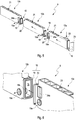
2 bis4 Ansichten von benachbarten Teilgehäusen mit einem Zentralfluidleitelement in der erfindungsgemäßen Batterieanordnung; -
5 bis7 Ansichten eines Zentralfluidleitelements in der erfindungsgemäßen Akkum ulatoranordnung; -
8 eine Schnittansicht des Zentralfluidleitelements in der erfindungsgemäßen Akkumulatoranordnung.
-
1 a view of a partial housing with battery modules in an accumulator arrangement according to the invention; -
2nd to4th Views of adjacent sub-housings with a central fluid guiding element in the battery arrangement according to the invention; -
5 to7 Views of a central fluid guide element in the accumulator arrangement according to the invention; -
8th a sectional view of the Zentralfluidleitelements in the battery assembly according to the invention.
An dem Teilgehäuse
In
Zusammenfassend weist die erfindungsgemäße Akkumulatoranordnung
ZITATE ENTHALTEN IN DER BESCHREIBUNG QUOTES INCLUDE IN THE DESCRIPTION
Diese Liste der vom Anmelder aufgeführten Dokumente wurde automatisiert erzeugt und ist ausschließlich zur besseren Information des Lesers aufgenommen. Die Liste ist nicht Bestandteil der deutschen Patent- bzw. Gebrauchsmusteranmeldung. Das DPMA übernimmt keinerlei Haftung für etwaige Fehler oder Auslassungen.This list of documents listed by the applicant has been generated automatically and is only included for the better information of the reader. The list is not part of the German patent or utility model application. The DPMA assumes no liability for any errors or omissions.
Zitierte PatentliteraturPatent literature cited
- DE 102016114216 A1 [0003]DE 102016114216 A1 [0003]
Claims (11)
Applications Claiming Priority (2)
| Application Number | Priority Date | Filing Date | Title |
|---|---|---|---|
| DE102018215544.5 | 2018-09-12 | ||
| DE102018215544 | 2018-09-12 |
Publications (1)
| Publication Number | Publication Date |
|---|---|
| DE102019213424A1 true DE102019213424A1 (en) | 2020-03-12 |
Family
ID=69621671
Family Applications (1)
| Application Number | Title | Priority Date | Filing Date |
|---|---|---|---|
| DE102019213424.6A Pending DE102019213424A1 (en) | 2018-09-12 | 2019-09-04 | Accumulator arrangement |
Country Status (3)
| Country | Link |
|---|---|
| US (1) | US20200079241A1 (en) |
| CN (1) | CN110896136A (en) |
| DE (1) | DE102019213424A1 (en) |
Cited By (3)
| Publication number | Priority date | Publication date | Assignee | Title |
|---|---|---|---|---|
| DE102021209746A1 (en) | 2021-09-03 | 2023-03-09 | Mahle International Gmbh | Housing for a traction battery |
| DE102023117870A1 (en) | 2023-07-06 | 2025-01-09 | Dr. Ing. H.C. F. Porsche Aktiengesellschaft | Battery module, battery assembly and battery-electric vehicle |
| DE102023209129A1 (en) * | 2023-09-20 | 2025-03-20 | Mahle International Gmbh | battery |
Families Citing this family (1)
| Publication number | Priority date | Publication date | Assignee | Title |
|---|---|---|---|---|
| EP4147297A4 (en) * | 2020-05-04 | 2024-08-07 | Fluence Energy, LLC | Energy storage system with removable, adjustable, and lightweight plenums |
Family Cites Families (8)
| Publication number | Priority date | Publication date | Assignee | Title |
|---|---|---|---|---|
| KR20070013455A (en) * | 2005-07-26 | 2007-01-31 | 삼성에스디아이 주식회사 | Secondary battery module |
| JP2007172982A (en) * | 2005-12-21 | 2007-07-05 | Toyota Motor Corp | Battery pack |
| JP5978214B2 (en) * | 2010-09-02 | 2016-08-24 | アカソル・ゲゼルシャフト・ミット・ベシュレンクテル・ハフツング | Cooling module and method for manufacturing cooling module |
| CN103380511B (en) * | 2011-01-10 | 2016-08-10 | 科瓦西斯有限责任公司 | Adaptive battery modules for prismatic cells |
| US9761917B2 (en) * | 2013-09-30 | 2017-09-12 | Panasonic Intellectual Property Management Co., Ltd. | Battery unit |
| US9446681B2 (en) * | 2014-01-29 | 2016-09-20 | GM Global Technology Operations LLC | Flow uniformity of air-cooled battery packs |
| US20170288286A1 (en) * | 2016-04-01 | 2017-10-05 | Faraday&Future Inc. | Liquid temperature regulated battery pack for electric vehicles |
| DE102016114216A1 (en) * | 2016-08-01 | 2018-02-01 | Kirchhoff Automotive Deutschland Gmbh | Tempering device for a battery case of a vehicle |
-
2019
- 2019-09-04 DE DE102019213424.6A patent/DE102019213424A1/en active Pending
- 2019-09-11 US US16/568,222 patent/US20200079241A1/en not_active Abandoned
- 2019-09-11 CN CN201910857233.6A patent/CN110896136A/en active Pending
Cited By (4)
| Publication number | Priority date | Publication date | Assignee | Title |
|---|---|---|---|---|
| DE102021209746A1 (en) | 2021-09-03 | 2023-03-09 | Mahle International Gmbh | Housing for a traction battery |
| US12519157B2 (en) | 2021-09-03 | 2026-01-06 | Mahle International Gmbh | Housing for a traction battery |
| DE102023117870A1 (en) | 2023-07-06 | 2025-01-09 | Dr. Ing. H.C. F. Porsche Aktiengesellschaft | Battery module, battery assembly and battery-electric vehicle |
| DE102023209129A1 (en) * | 2023-09-20 | 2025-03-20 | Mahle International Gmbh | battery |
Also Published As
| Publication number | Publication date |
|---|---|
| US20200079241A1 (en) | 2020-03-12 |
| CN110896136A (en) | 2020-03-20 |
Similar Documents
| Publication | Publication Date | Title |
|---|---|---|
| DE102019213424A1 (en) | Accumulator arrangement | |
| DE102017204194B4 (en) | Energy storage device with cooling device and motor vehicle with an energy storage device | |
| DE102014114023A1 (en) | battery system | |
| DE19504687C1 (en) | Battery casing housing electrochemical battery cells | |
| DE102013100545A1 (en) | Accumulator unit for a watercraft | |
| DE102017118519A1 (en) | Temperature control device for a battery case | |
| DE102009009700A1 (en) | Electrical energy storage unit for motor vehicles | |
| DE102018220937A1 (en) | Battery module | |
| DE102017206283A1 (en) | Cell module for a high-voltage energy storage of a motor vehicle | |
| DE102018219249A1 (en) | Accumulator arrangement | |
| DE102012021990A1 (en) | Arrangement for electrical energy storage device and cooling device of commercial vehicle, has cooling elements that are connected to common coolant supply of cooling device | |
| DE102016209378A1 (en) | Battery composite | |
| DE102017217108A1 (en) | Battery cell, method for its manufacture and battery module | |
| DE102017217114A1 (en) | battery module | |
| DE102019132687A1 (en) | Power storage battery and corresponding heat control element | |
| DE102016109277A1 (en) | battery module | |
| DE102020121842A1 (en) | BATTERY MODULE ARRANGEMENT AND ASSEMBLY PROCEDURE FOR IT | |
| DE102019218201A1 (en) | Traction battery and a battery electric vehicle with the traction battery | |
| DE102021133850A1 (en) | fluid line connection assembly | |
| DE102011107075A1 (en) | Battery module for use with air conditioner in e.g. hybrid vehicle, has cell modules connected with radiator in which passages are inserted, and is integrated such that passages are vertically arranged to support plate | |
| DE102018218216A1 (en) | Accumulator arrangement | |
| DE102016210138A1 (en) | Temperature control device of a battery module and battery module | |
| WO2018234098A1 (en) | BATTERY HOUSING FOR A VEHICLE BATTERY | |
| DE102011009000A1 (en) | Heat exchanger for electrochemical energy store of battery for vehicle, has flow channels that are arranged vertically one above other and are provided adjacent to heat exchanger planes for flowing flow medium at moderate temperature | |
| DE102017217118A1 (en) | battery module |