DE102019206021A1 - Method for detecting the functionality of an environmental sensor, control unit and vehicle - Google Patents
Method for detecting the functionality of an environmental sensor, control unit and vehicle Download PDFInfo
- Publication number
- DE102019206021A1 DE102019206021A1 DE102019206021.8A DE102019206021A DE102019206021A1 DE 102019206021 A1 DE102019206021 A1 DE 102019206021A1 DE 102019206021 A DE102019206021 A DE 102019206021A DE 102019206021 A1 DE102019206021 A1 DE 102019206021A1
- Authority
- DE
- Germany
- Prior art keywords
- vehicle
- sensor
- function
- environment
- functionality
- Prior art date
- Legal status (The legal status is an assumption and is not a legal conclusion. Google has not performed a legal analysis and makes no representation as to the accuracy of the status listed.)
- Pending
Links
Images




Classifications
-
- G—PHYSICS
- G01—MEASURING; TESTING
- G01C—MEASURING DISTANCES, LEVELS OR BEARINGS; SURVEYING; NAVIGATION; GYROSCOPIC INSTRUMENTS; PHOTOGRAMMETRY OR VIDEOGRAMMETRY
- G01C21/00—Navigation; Navigational instruments not provided for in groups G01C1/00 - G01C19/00
- G01C21/26—Navigation; Navigational instruments not provided for in groups G01C1/00 - G01C19/00 specially adapted for navigation in a road network
- G01C21/34—Route searching; Route guidance
- G01C21/36—Input/output arrangements for on-board computers
- G01C21/3602—Input other than that of destination using image analysis, e.g. detection of road signs, lanes, buildings, real preceding vehicles using a camera
-
- G—PHYSICS
- G06—COMPUTING OR CALCULATING; COUNTING
- G06V—IMAGE OR VIDEO RECOGNITION OR UNDERSTANDING
- G06V20/00—Scenes; Scene-specific elements
- G06V20/50—Context or environment of the image
- G06V20/56—Context or environment of the image exterior to a vehicle by using sensors mounted on the vehicle
- G06V20/58—Recognition of moving objects or obstacles, e.g. vehicles or pedestrians; Recognition of traffic objects, e.g. traffic signs, traffic lights or roads
-
- B—PERFORMING OPERATIONS; TRANSPORTING
- B60—VEHICLES IN GENERAL
- B60W—CONJOINT CONTROL OF VEHICLE SUB-UNITS OF DIFFERENT TYPE OR DIFFERENT FUNCTION; CONTROL SYSTEMS SPECIALLY ADAPTED FOR HYBRID VEHICLES; ROAD VEHICLE DRIVE CONTROL SYSTEMS FOR PURPOSES NOT RELATED TO THE CONTROL OF A PARTICULAR SUB-UNIT
- B60W40/00—Estimation or calculation of non-directly measurable driving parameters for road vehicle drive control systems not related to the control of a particular sub unit, e.g. by using mathematical models
- B60W40/10—Estimation or calculation of non-directly measurable driving parameters for road vehicle drive control systems not related to the control of a particular sub unit, e.g. by using mathematical models related to vehicle motion
-
- B—PERFORMING OPERATIONS; TRANSPORTING
- B60—VEHICLES IN GENERAL
- B60W—CONJOINT CONTROL OF VEHICLE SUB-UNITS OF DIFFERENT TYPE OR DIFFERENT FUNCTION; CONTROL SYSTEMS SPECIALLY ADAPTED FOR HYBRID VEHICLES; ROAD VEHICLE DRIVE CONTROL SYSTEMS FOR PURPOSES NOT RELATED TO THE CONTROL OF A PARTICULAR SUB-UNIT
- B60W40/00—Estimation or calculation of non-directly measurable driving parameters for road vehicle drive control systems not related to the control of a particular sub unit, e.g. by using mathematical models
- B60W40/12—Estimation or calculation of non-directly measurable driving parameters for road vehicle drive control systems not related to the control of a particular sub unit, e.g. by using mathematical models related to parameters of the vehicle itself, e.g. tyre models
-
- G—PHYSICS
- G01—MEASURING; TESTING
- G01C—MEASURING DISTANCES, LEVELS OR BEARINGS; SURVEYING; NAVIGATION; GYROSCOPIC INSTRUMENTS; PHOTOGRAMMETRY OR VIDEOGRAMMETRY
- G01C25/00—Manufacturing, calibrating, cleaning, or repairing instruments or devices referred to in the other groups of this subclass
-
- G—PHYSICS
- G01—MEASURING; TESTING
- G01S—RADIO DIRECTION-FINDING; RADIO NAVIGATION; DETERMINING DISTANCE OR VELOCITY BY USE OF RADIO WAVES; LOCATING OR PRESENCE-DETECTING BY USE OF THE REFLECTION OR RERADIATION OF RADIO WAVES; ANALOGOUS ARRANGEMENTS USING OTHER WAVES
- G01S13/00—Systems using the reflection or reradiation of radio waves, e.g. radar systems; Analogous systems using reflection or reradiation of waves whose nature or wavelength is irrelevant or unspecified
- G01S13/88—Radar or analogous systems specially adapted for specific applications
- G01S13/93—Radar or analogous systems specially adapted for specific applications for anti-collision purposes
- G01S13/931—Radar or analogous systems specially adapted for specific applications for anti-collision purposes of land vehicles
-
- G—PHYSICS
- G01—MEASURING; TESTING
- G01S—RADIO DIRECTION-FINDING; RADIO NAVIGATION; DETERMINING DISTANCE OR VELOCITY BY USE OF RADIO WAVES; LOCATING OR PRESENCE-DETECTING BY USE OF THE REFLECTION OR RERADIATION OF RADIO WAVES; ANALOGOUS ARRANGEMENTS USING OTHER WAVES
- G01S15/00—Systems using the reflection or reradiation of acoustic waves, e.g. sonar systems
- G01S15/88—Sonar systems specially adapted for specific applications
- G01S15/93—Sonar systems specially adapted for specific applications for anti-collision purposes
- G01S15/931—Sonar systems specially adapted for specific applications for anti-collision purposes of land vehicles
-
- G—PHYSICS
- G01—MEASURING; TESTING
- G01S—RADIO DIRECTION-FINDING; RADIO NAVIGATION; DETERMINING DISTANCE OR VELOCITY BY USE OF RADIO WAVES; LOCATING OR PRESENCE-DETECTING BY USE OF THE REFLECTION OR RERADIATION OF RADIO WAVES; ANALOGOUS ARRANGEMENTS USING OTHER WAVES
- G01S17/00—Systems using the reflection or reradiation of electromagnetic waves other than radio waves, e.g. lidar systems
- G01S17/88—Lidar systems specially adapted for specific applications
- G01S17/93—Lidar systems specially adapted for specific applications for anti-collision purposes
- G01S17/931—Lidar systems specially adapted for specific applications for anti-collision purposes of land vehicles
-
- G—PHYSICS
- G01—MEASURING; TESTING
- G01S—RADIO DIRECTION-FINDING; RADIO NAVIGATION; DETERMINING DISTANCE OR VELOCITY BY USE OF RADIO WAVES; LOCATING OR PRESENCE-DETECTING BY USE OF THE REFLECTION OR RERADIATION OF RADIO WAVES; ANALOGOUS ARRANGEMENTS USING OTHER WAVES
- G01S7/00—Details of systems according to groups G01S13/00, G01S15/00, G01S17/00
- G01S7/02—Details of systems according to groups G01S13/00, G01S15/00, G01S17/00 of systems according to group G01S13/00
- G01S7/40—Means for monitoring or calibrating
- G01S7/4004—Means for monitoring or calibrating of parts of a radar system
- G01S7/4026—Antenna boresight
-
- G—PHYSICS
- G01—MEASURING; TESTING
- G01S—RADIO DIRECTION-FINDING; RADIO NAVIGATION; DETERMINING DISTANCE OR VELOCITY BY USE OF RADIO WAVES; LOCATING OR PRESENCE-DETECTING BY USE OF THE REFLECTION OR RERADIATION OF RADIO WAVES; ANALOGOUS ARRANGEMENTS USING OTHER WAVES
- G01S7/00—Details of systems according to groups G01S13/00, G01S15/00, G01S17/00
- G01S7/02—Details of systems according to groups G01S13/00, G01S15/00, G01S17/00 of systems according to group G01S13/00
- G01S7/41—Details of systems according to groups G01S13/00, G01S15/00, G01S17/00 of systems according to group G01S13/00 using analysis of echo signal for target characterisation; Target signature; Target cross-section
- G01S7/411—Identification of targets based on measurements of radar reflectivity
- G01S7/412—Identification of targets based on measurements of radar reflectivity based on a comparison between measured values and known or stored values
-
- G—PHYSICS
- G01—MEASURING; TESTING
- G01S—RADIO DIRECTION-FINDING; RADIO NAVIGATION; DETERMINING DISTANCE OR VELOCITY BY USE OF RADIO WAVES; LOCATING OR PRESENCE-DETECTING BY USE OF THE REFLECTION OR RERADIATION OF RADIO WAVES; ANALOGOUS ARRANGEMENTS USING OTHER WAVES
- G01S7/00—Details of systems according to groups G01S13/00, G01S15/00, G01S17/00
- G01S7/48—Details of systems according to groups G01S13/00, G01S15/00, G01S17/00 of systems according to group G01S17/00
- G01S7/497—Means for monitoring or calibrating
-
- G—PHYSICS
- G01—MEASURING; TESTING
- G01S—RADIO DIRECTION-FINDING; RADIO NAVIGATION; DETERMINING DISTANCE OR VELOCITY BY USE OF RADIO WAVES; LOCATING OR PRESENCE-DETECTING BY USE OF THE REFLECTION OR RERADIATION OF RADIO WAVES; ANALOGOUS ARRANGEMENTS USING OTHER WAVES
- G01S7/00—Details of systems according to groups G01S13/00, G01S15/00, G01S17/00
- G01S7/52—Details of systems according to groups G01S13/00, G01S15/00, G01S17/00 of systems according to group G01S15/00
- G01S7/52004—Means for monitoring or calibrating
-
- B—PERFORMING OPERATIONS; TRANSPORTING
- B60—VEHICLES IN GENERAL
- B60W—CONJOINT CONTROL OF VEHICLE SUB-UNITS OF DIFFERENT TYPE OR DIFFERENT FUNCTION; CONTROL SYSTEMS SPECIALLY ADAPTED FOR HYBRID VEHICLES; ROAD VEHICLE DRIVE CONTROL SYSTEMS FOR PURPOSES NOT RELATED TO THE CONTROL OF A PARTICULAR SUB-UNIT
- B60W2420/00—Indexing codes relating to the type of sensors based on the principle of their operation
- B60W2420/40—Photo, light or radio wave sensitive means, e.g. infrared sensors
- B60W2420/403—Image sensing, e.g. optical camera
-
- B—PERFORMING OPERATIONS; TRANSPORTING
- B60—VEHICLES IN GENERAL
- B60W—CONJOINT CONTROL OF VEHICLE SUB-UNITS OF DIFFERENT TYPE OR DIFFERENT FUNCTION; CONTROL SYSTEMS SPECIALLY ADAPTED FOR HYBRID VEHICLES; ROAD VEHICLE DRIVE CONTROL SYSTEMS FOR PURPOSES NOT RELATED TO THE CONTROL OF A PARTICULAR SUB-UNIT
- B60W2554/00—Input parameters relating to objects
- B60W2554/40—Dynamic objects, e.g. animals, windblown objects
- B60W2554/404—Characteristics
- B60W2554/4041—Position
-
- B—PERFORMING OPERATIONS; TRANSPORTING
- B60—VEHICLES IN GENERAL
- B60W—CONJOINT CONTROL OF VEHICLE SUB-UNITS OF DIFFERENT TYPE OR DIFFERENT FUNCTION; CONTROL SYSTEMS SPECIALLY ADAPTED FOR HYBRID VEHICLES; ROAD VEHICLE DRIVE CONTROL SYSTEMS FOR PURPOSES NOT RELATED TO THE CONTROL OF A PARTICULAR SUB-UNIT
- B60W2554/00—Input parameters relating to objects
- B60W2554/40—Dynamic objects, e.g. animals, windblown objects
- B60W2554/404—Characteristics
- B60W2554/4049—Relationship among other objects, e.g. converging dynamic objects
-
- G—PHYSICS
- G01—MEASURING; TESTING
- G01C—MEASURING DISTANCES, LEVELS OR BEARINGS; SURVEYING; NAVIGATION; GYROSCOPIC INSTRUMENTS; PHOTOGRAMMETRY OR VIDEOGRAMMETRY
- G01C21/00—Navigation; Navigational instruments not provided for in groups G01C1/00 - G01C19/00
- G01C21/26—Navigation; Navigational instruments not provided for in groups G01C1/00 - G01C19/00 specially adapted for navigation in a road network
- G01C21/28—Navigation; Navigational instruments not provided for in groups G01C1/00 - G01C19/00 specially adapted for navigation in a road network with correlation of data from several navigational instruments
- G01C21/30—Map- or contour-matching
-
- G—PHYSICS
- G01—MEASURING; TESTING
- G01S—RADIO DIRECTION-FINDING; RADIO NAVIGATION; DETERMINING DISTANCE OR VELOCITY BY USE OF RADIO WAVES; LOCATING OR PRESENCE-DETECTING BY USE OF THE REFLECTION OR RERADIATION OF RADIO WAVES; ANALOGOUS ARRANGEMENTS USING OTHER WAVES
- G01S7/00—Details of systems according to groups G01S13/00, G01S15/00, G01S17/00
- G01S7/02—Details of systems according to groups G01S13/00, G01S15/00, G01S17/00 of systems according to group G01S13/00
- G01S7/40—Means for monitoring or calibrating
- G01S7/4052—Means for monitoring or calibrating by simulation of echoes
- G01S7/4082—Means for monitoring or calibrating by simulation of echoes using externally generated reference signals, e.g. via remote reflector or transponder
- G01S7/4091—Means for monitoring or calibrating by simulation of echoes using externally generated reference signals, e.g. via remote reflector or transponder during normal radar operation
Landscapes
- Engineering & Computer Science (AREA)
- Radar, Positioning & Navigation (AREA)
- Remote Sensing (AREA)
- Physics & Mathematics (AREA)
- General Physics & Mathematics (AREA)
- Computer Networks & Wireless Communication (AREA)
- Automation & Control Theory (AREA)
- Transportation (AREA)
- Mechanical Engineering (AREA)
- Mathematical Physics (AREA)
- Electromagnetism (AREA)
- Multimedia (AREA)
- Theoretical Computer Science (AREA)
- Acoustics & Sound (AREA)
- Manufacturing & Machinery (AREA)
- Computer Vision & Pattern Recognition (AREA)
- Traffic Control Systems (AREA)
- Navigation (AREA)
Abstract
Verfahren zur Erkennung einer Funktionsfähigkeit eines Umgebungssensors eines Fahrzeugs (100), umfassend folgende Schritte: Ermittlung (220) von aktuellen Koordinaten (X, Y) des Fahrzeugs (100); Ermittlung (240) einer aktuellen Ausrichtung (φ) des Fahrzeugs (100); Bestimmung (250) mindestens eines Objektes (310) in der Umgebung (190) des Fahrzeugs (100) und einer Soll-Position (Z1, Z2) des Objektes (310) bezüglich des Fahrzeugs (100) in Abhängigkeit der ermittelten Koordinaten (X, Y), der ermittelten Ausrichtung (φ), einer vorbestimmten Position des Umgebungssensors am Fahrzeug (100) und einer Karte (300) der Umgebung (190), wobei die Karte (300) wenigstens das Objekt (310) und eine Lage des Objektes (310) umfasst; Erfassung (260) der Umgebung (190) des Fahrzeugs (100) mittels des Umgebungssensors; Erzeugung (270) von Umgebungsdaten in Abhängigkeit der erfassten Umgebung (190); Erkennung (280) einer Ist-Position (W1, W2) des bestimmten Objektes (310) in der Umgebung (190) des Fahrzeugs (100) in Abhängigkeit der Umgebungsdaten; und Erkennung (290) einer Funktionsfähigkeit des Umgebungssensors durch Vergleich der Ist-Position (W1, W2) des Objektes (310) mit der Soll-Position (Z1, Z2) des Objektes (310); und/oder Kalibrierung (291) des Umgebungssensors in Abhängigkeit der Ist-Position (W1, W2) und der Soll-Position (Z1, Z2).A method for recognizing the functionality of an environmental sensor of a vehicle (100), comprising the following steps: determining (220) current coordinates (X, Y) of the vehicle (100); Determining (240) a current orientation (φ) of the vehicle (100); Determination (250) of at least one object (310) in the surroundings (190) of the vehicle (100) and a target position (Z1, Z2) of the object (310) with respect to the vehicle (100) as a function of the determined coordinates (X, Y), the determined orientation (φ), a predetermined position of the environment sensor on the vehicle (100) and a map (300) of the environment (190), the map (300) at least the object (310) and a position of the object ( 310) includes; Detection (260) of the surroundings (190) of the vehicle (100) by means of the surroundings sensor; Generation (270) of environment data as a function of the detected environment (190); Recognition (280) of an actual position (W1, W2) of the specific object (310) in the surroundings (190) of the vehicle (100) as a function of the surroundings data; and detection (290) of the functionality of the environmental sensor by comparing the actual position (W1, W2) of the object (310) with the target position (Z1, Z2) of the object (310); and / or calibration (291) of the environmental sensor as a function of the actual position (W1, W2) and the target position (Z1, Z2).
Description
Die vorliegende Erfindung betrifft ein Verfahren zur Erkennung einer Funktionsfähigkeit eines Umgebungssensors, ein Steuergerät zur Durchführung des Verfahrens sowie ein Fahrzeug mit dem Steuergerät.The present invention relates to a method for recognizing the functionality of an environmental sensor, a control device for carrying out the method, and a vehicle with the control device.
Stand der TechnikState of the art
Um beim autonomen oder teilautonomen Fahren eines Fahrzeugs basierend auf Sensordaten eine ausreichende Zuverlässigkeit zu erreichen, sollte der Sensor beziehungsweise sollten die Sensoren zur Erzeugung der Sensordaten eine vorbestimmte Genauigkeit aufweisen. Zusätzlich sollte die Einbauposition des Sensors und eine Ausrichtung des Sensors ausreichend genau bekannt sein beziehungsweise eine entsprechende Kalibrierung des Sensors durchgeführt werden. Die Kalibrierung kann aufwendig sein und somit schon in einer Fertigung des Fahrzeugs hohe Kosten verursachen.In order to achieve sufficient reliability in the autonomous or semi-autonomous driving of a vehicle based on sensor data, the sensor or the sensors for generating the sensor data should have a predetermined accuracy. In addition, the installation position of the sensor and an alignment of the sensor should be known with sufficient accuracy or a corresponding calibration of the sensor should be carried out. The calibration can be complex and thus cause high costs even in the manufacture of the vehicle.
Die Aufgabe der vorliegenden Erfindung ist es, eine Funktion eines Umgebungssensors an einem Fahrzeug verbessert zu erkennen, insbesondere um den Umgebungssensor zu kalibrieren.The object of the present invention is to better identify a function of an environment sensor on a vehicle, in particular to calibrate the environment sensor.
Offenbarung der ErfindungDisclosure of the invention
Die vorstehende Aufgabe wird durch ein Verfahren nach Anspruch 1 sowie durch ein Steuergerät nach Anspruch 14 und ein Fahrzeug nach Anspruch 15 gelöst.The above object is achieved by a method according to
Die vorliegende Erfindung betrifft ein Verfahren zur Erkennung einer Funktionsfähigkeit eines Umgebungssensors eines Fahrzeugs. Das Verfahren umfasst eine Ermittlung von aktuellen Koordinaten des Fahrzeugs. Die aktuellen Koordinaten des Fahrzeugs sind beispielsweise Koordinaten eines satellitenbasieren Navigationssystems, welche mittels eines Sensors erfasst werden. Das Verfahren weist ferner eine Ermittlung einer aktuellen Ausrichtung des Fahrzeugs an den aktuellen Koordinaten auf. Diese aktuelle Ausrichtung des Fahrzeugs ist beispielsweise ein Gierwinkel beziehungsweise eine Orientierung des Fahrzeugs im Sinne eines Kompasses. Anschließend wird mindestens ein Objekt in der Umgebung des Fahrzeugs und eine Soll-Position des Objektes bezüglich des Fahrzeugs in Abhängigkeit der ermittelten Koordinaten, der ermittelten Ausrichtung, einer vorbestimmten Position des Umgebungssensors am Fahrzeug und einer Karte der Umgebung bestimmt. Beispielsweise wird für eine am Fahrzeug in Fahrtrichtung rechts angeordnete Kamera, welche als Spiegelersatz verwendet wird, basierend auf der ermittelten Ausrichtung des Fahrzeugs ein für die Kamera sichtbarer Ausschnitt der Karte ermittelt und in diesem Kartenausschnitt das Objekt sowie die Soll-Position des Objektes bezüglich des Fahrzeugs erkannt beziehungsweise bestimmt, wobei das Objekt vorzugsweise leicht erkennbar beziehungsweise identifizierbar und/oder in einen vorbestimmten Abstandsbereich zum Fahrzeug liegt. Die Karte umfasst wenigstens das Objekt und eine Lage des Objektes. Vorzugsweise erfolgt die Bestimmung des Objektes und der Soll-Position des bestimmten Objektes in der Umgebung des Fahrzeugs zumindest teilweise mittels einer angelernten maschinellen Erkennung, bevorzugt mittels eines neuronalen Netzes. Die Karte ist vorteilhafterweise eine hochgenaue Karte, welche eine Auflösung kleiner als 1 Meter aufweist. Des Weiteren wird eine Erfassung der Umgebung des Fahrzeugs mittels des Umgebungssensors des Fahrzeugs durchgeführt, beispielsweise mittels der am Fahrzeug in Fahrtrichtung rechts angeordneten Kamera. In Abhängigkeit der erfassten Umgebung werden Umgebungsdaten erzeugt. Die Umgebungsdaten können vorzugsweise in Abhängigkeit von mindestens zwei Umgebungssensoren erzeugt werden, wobei die Umgebungssensoren gleich oder alternativ unterschiedliche Sensortypen verwendet werden, beispielsweise werden die Umgebungsdaten in Abhängigkeit einer Kamera und/oder eines Lidarsensors und/oder eines Radarsensors und/oder eines Ultraschallsensors erzeugt. Anschließend wird eine Ist-Position des bestimmten Objektes in der Umgebung des Fahrzeugs in Abhängigkeit der Umgebungsdaten erkannt beziehungsweise ermittelt. Beispielsweise wird das Objekt in einem Kamerabild durch eine künstliche Intelligenz beziehungsweise ein angelerntes maschinelles Erkennungsverfahren beziehungsweise ein neuronales Netz erkannt und ein Abstand des Objektes zum Fahrzeug basierend auf den Umgebungsdaten ermittelt, wobei die Umgebungsdaten bevorzugt Abstandsdaten zwischen Objekten in der Umgebung des Fahrzeugs und dem Fahrzeug umfassen. Anschließend wird eine Funktionsfähigkeit des Umgebungssensors durch Vergleich der erkannten beziehungsweise ermittelten Ist-Position des Objektes mit der ermittelten Soll-Position des Objektes erkannt beziehungsweise bestimmt. Alternativ zur Erkennung der Funktionsfähigkeit oder zusätzlich zur Erkennung der Funktionsfähigkeit wird der Umgebungssensor in Abhängigkeit der Ist-Position und der Soll-Position kalibriert. Durch das Verfahren resultiert der Vorteil, dass die Funktionsfähigkeit des Umgebungssensors schnell und kostengünstig und/oder eine Kalibrierung des Umgebungssensors im laufenden Betrieb durchgeführt werden kann, wobei keine künstlichen Markierungen an fest definierten Orten montiert werden müssen. Die Kalibrierung des Umgebungssensors des Fahrzeugs, beispielsweise einer Kamera und/oder einer Stereokamera und/oder eines Lidarsensors und/oder eines Radarsensors und/oder eines Ultraschallsensors erfolgt vorteilhafterweise zumindest ausreichend genau um ein Umgebungsmodell anschaulich und ohne Artefakte darzustellen und/oder eine teil- oder vollautomatische Fahrfunktion in Abhängigkeit des Umgebungssensors zumindest ausreichend zuverlässig zu realisieren.The present invention relates to a method for detecting the functionality of an environmental sensor of a vehicle. The method includes a determination of current coordinates of the vehicle. The current coordinates of the vehicle are, for example, coordinates of a satellite-based navigation system, which are recorded by means of a sensor. The method also includes a determination of a current orientation of the vehicle at the current coordinates. This current orientation of the vehicle is, for example, a yaw angle or an orientation of the vehicle in the sense of a compass. At least one object in the vicinity of the vehicle and a target position of the object with respect to the vehicle are then determined as a function of the determined coordinates, the determined orientation, a predetermined position of the environmental sensor on the vehicle and a map of the surroundings. For example, for a camera located on the right of the vehicle in the direction of travel, which is used as a mirror replacement, a section of the map visible to the camera is determined based on the determined orientation of the vehicle, and in this map section the object and the target position of the object with respect to the vehicle recognized or determined, the object preferably being easily recognizable or identifiable and / or lying in a predetermined distance range from the vehicle. The map includes at least the object and a location of the object. The object and the setpoint position of the particular object in the vicinity of the vehicle are preferably determined at least partially by means of a learned machine recognition, preferably by means of a neural network. The map is advantageously a highly accurate map with a resolution of less than 1 meter. Furthermore, a detection of the surroundings of the vehicle is carried out by means of the surroundings sensor of the vehicle, for example by means of the camera arranged on the vehicle on the right in the direction of travel. Environment data are generated depending on the captured environment. The environment data can preferably be generated as a function of at least two environment sensors, the environment sensors being used identically or alternatively different sensor types, for example the environment data is generated as a function of a camera and / or a lidar sensor and / or a radar sensor and / or an ultrasound sensor. An actual position of the specific object in the surroundings of the vehicle is then recognized or determined as a function of the environmental data. For example, the object in a camera image is recognized by an artificial intelligence or a learned machine recognition method or a neural network and a distance between the object and the vehicle is determined based on the environment data, the environment data preferably including distance data between objects in the vicinity of the vehicle and the vehicle . A functionality of the environmental sensor is then recognized or determined by comparing the recognized or determined actual position of the object with the determined target position of the object. As an alternative to recognizing the functionality or in addition to recognizing the functionality, the environmental sensor is calibrated as a function of the actual position and the target position. The method results in the advantage that the functionality of the environmental sensor can be carried out quickly and inexpensively and / or calibration of the environmental sensor can be carried out during operation, with no artificial markings having to be installed at fixed locations. The calibration of the environment sensor of the vehicle, for example a camera and / or a stereo camera and / or a lidar sensor and / or a radar sensor and / or an ultrasound sensor is advantageously carried out at least with sufficient accuracy in order to display an environment model clearly and without artifacts and / or partially or to realize fully automatic driving function at least sufficiently reliable depending on the environmental sensor.
In einer bevorzugten Ausgestaltung erfolgt die Ermittlung der Koordinaten des Fahrzeugs in Abhängigkeit erfasster Signale, welche mittels eines Ortssensors für ein globales Sattelitennavigationssystem empfangen werden, und/oder in Abhängigkeit wenigstens eines Kamerabildes einer Fahrzeugkamera, und/oder in Abhängigkeit von erfassten Abstandsdaten zwischen dem Fahrzeug und Objekten in der Umgebung des Fahrzeugs, und/oder in Abhängigkeit von Odometriedaten des Fahrzeugs. Diese Ausgestaltung, insbesondere bei Kombination der Abhängigkeiten, erlaubt vorteilhafterweise eine hochgenaue Ermittlung der Koordinaten des Fahrzeuges. Alternativ oder zusätzlich erfolgt die Ermittlung der Koordinaten des Fahrzeugs in Abhängigkeit wenigstens einer bestimmten Laufzeit eines erfassten Car-to-X Kommunikationssignals zwischen dem Fahrzeug und einer ortsfesten Infrastruktureinrichtung.In a preferred embodiment, the coordinates of the vehicle are determined as a function of recorded signals which are received by means of a location sensor for a global satellite navigation system, and / or as a function of at least one camera image from a vehicle camera, and / or as a function of recorded distance data between the vehicle and Objects in the vicinity of the vehicle and / or as a function of odometry data from the vehicle. This embodiment, in particular when combining the dependencies, advantageously allows the coordinates of the vehicle to be determined with high precision. As an alternative or in addition, the determination of the coordinates of the vehicle takes place as a function of at least one specific transit time of a detected car-to-x communication signal between the vehicle and a stationary infrastructure facility.
In einer weiteren bevorzugten Ausführung erfolgt die Ermittlung der Ausrichtung des Fahrzeugs in Abhängigkeit von Signalen eines Magnetometers, und/oder in Abhängigkeit von Signalen wenigstens einer inertialen Messeinheit, und/oder in Abhängigkeit eines Verlaufs von, insbesondere über eine vorgegebene Zeitspanne, ermittelten Koordinaten des Fahrzeugs. Diese Ausführung, insbesondere bei Kombination der Abhängigkeiten, erlaubt vorteilhafterweise eine hochgenaue Ermittlung der Ausrichtung des Fahrzeuges.In a further preferred embodiment, the orientation of the vehicle is determined as a function of signals from a magnetometer, and / or as a function of signals from at least one inertial measuring unit, and / or as a function of a course of coordinates of the vehicle determined, in particular over a predetermined period of time . This embodiment, in particular when combining the dependencies, advantageously allows the alignment of the vehicle to be determined with high precision.
In einer Weiterführung erfolgt die Ermittlung der Koordinaten und/oder die Ermittlung der Ausrichtung des Fahrzeugs zusätzlich in Abhängigkeit einer empfangenen Positionsinformation, wobei die empfangene Positionsinformation von einer Infrastruktur-Überwachungseinrichtung in der Umgebung des Fahrzeugs ausgesendet beziehungsweise übermittelt wird. Beispielsweise wird die Positionsinformation mittels einer Abstandssensorik der Infrastruktur-Überwachungseinrichtung erfasst, wobei die Positionsinformationen in einer optionalen Ausgestaltung zusätzlich eine Information über die Ausrichtung des Fahrzeugs umfasst. Die Infrastruktur-Überwachungseinrichtung ist ortsfest angeordnet beziehungsweise ist der Standort der Infrastruktur-Überwachungseinrichtung genau bekannt. Die mittels der Abstandssensorik erfassten Daten beziehungsweise erfasste Infrastrukturinformation beziehungsweise erfasste Positionsinformation wird an das Fahrzeug gesendet beziehungsweise übermittelt. Beispielsweise weist die Infrastruktur-Überwachungseinrichtung als Abstandssensorik einen Lidarsensor und/oder eine Stereo-Kamera mit entsprechender Auswerteelektronik auf. Folglich sind in dieser Weiterführung die Ermittlung der Koordinaten und/oder die Ermittlung der Ausrichtung in Abhängigkeit der übermittelten Positionsinformation vorteilhafterweise besonders genau.In a continuation, the determination of the coordinates and / or the determination of the orientation of the vehicle also takes place as a function of received position information, the received position information being transmitted or transmitted by an infrastructure monitoring device in the vicinity of the vehicle. For example, the position information is acquired by means of a distance sensor system of the infrastructure monitoring device, the position information additionally including information about the orientation of the vehicle in an optional embodiment. The infrastructure monitoring device is arranged in a stationary manner or the location of the infrastructure monitoring device is precisely known. The data or infrastructure information or position information recorded by means of the distance sensor system is sent or transmitted to the vehicle. For example, the infrastructure monitoring device has a lidar sensor and / or a stereo camera with corresponding evaluation electronics as the distance sensor system. Consequently, in this continuation, the determination of the coordinates and / or the determination of the alignment as a function of the transmitted position information are advantageously particularly accurate.
In einer Ausgestaltung weist die in der Karte angegebene Lage des Objektes eine Genauigkeit kleiner als 1 Meter auf. Vorzugsweise ist die Genauigkeit der Lage des Objektes in der Karte kleiner als 10 Zentimeter und besonders bevorzugt kleiner oder gleich 1 Zentimeter. Durch die hohe Genauigkeit der Karte beziehungsweise der Lage des Objekts, kann die Funktionsfähigkeit des Umgebungssensors vorteilhafterweise genau und schnell sowie zuverlässig erkannt werden.In one embodiment, the position of the object indicated in the map has an accuracy of less than 1 meter. The accuracy of the position of the object in the map is preferably less than 10 centimeters and particularly preferably less than or equal to 1 centimeter. Due to the high accuracy of the map or the position of the object, the functionality of the environmental sensor can advantageously be recognized precisely, quickly and reliably.
In einer bevorzugten Weiterführung unterschreitet die Soll-Position des bestimmten Objektes nicht einen vorbestimmten Abstand des Objektes zum Fahrzeug. Die Genauigkeit der Karte beziehungsweise der Lage des Objekts ist dadurch vorteilhafterweise weniger relevant zur Erkennung beziehungsweise Ermittlung der Funktionsfähigkeit des Umgebungssensors. Das Verfahren wird in dieser Weiterführung folglich wesentlich robuster. Dadurch resultiert ferner vorteilhafterweise der technische Effekt, dass die Funktionsfähigkeit des Umgebungssensors sehr genau erkannt werden kann.In a preferred development, the target position of the specific object does not fall below a predetermined distance between the object and the vehicle. The accuracy of the map or the position of the object is therefore advantageously less relevant for the detection or determination of the functionality of the environmental sensor. As a result, the method becomes much more robust in this continuation. This also advantageously results in the technical effect that the functionality of the environmental sensor can be recognized very precisely.
Vorzugsweise erfolgt die Erkennung der Ist-Position des bestimmten Objektes in der Umgebung des Fahrzeugs in Abhängigkeit der Umgebungsdaten zumindest teilweise mittels einer angelernten maschinellen Erkennung, bevorzugt mittels eines neuronalen Netzes. Durch die angelernte maschinelle Erkennung beziehungsweise eine künstliche Intelligenz können Objekte schnell und zuverlässig erkannt werden. Die Ist-Position des erkannten Objektes ist dann vorteilhafterweise einfach aus den Umgebungsdaten auslesbar.The actual position of the specific object in the vicinity of the vehicle is preferably recognized as a function of the environmental data, at least in part by means of a learned machine recognition, preferably by means of a neural network. Objects can be recognized quickly and reliably thanks to the learned machine recognition or artificial intelligence. The actual position of the recognized object can then advantageously be easily read from the surrounding data.
In einer anderen Ausgestaltung wird nach der Erkennung der Funktionsfähigkeit des Umgebungssensors der Umgebungssensor in Abhängigkeit der erkannten Funktionsfähigkeit deaktiviert. Dadurch wird vorteilhafterweise beispielsweise eine ungenaue Anzeige eines Umgebungsmodells mit Bildartefakten und/oder eine unzuverlässige teil- oder vollautomatische Fahrfunktion in Abhängigkeit eines fehlerhaften Betriebs des Umgebungssensors vermieden.In another embodiment, after the functionality of the environmental sensor has been recognized, the environmental sensor is deactivated as a function of the recognized functionality. This advantageously results in, for example, an imprecise display of a Environment model with image artifacts and / or an unreliable partially or fully automatic driving function depending on incorrect operation of the environment sensor avoided.
In einer weiteren Ausführung erfolgt eine Aktivierung eines Sicherheitssensors und/oder eines alternativen Umgebungsüberwachungssystems des Fahrzeugs in Abhängigkeit der erkannten Funktionsfähigkeit, insbesondere fehlerhaften Funktionsfähigkeit, wobei der Sicherheitssensor den Umgebungssensor zumindest teilweise ersetzt. Dadurch wird vorteilhafterweise eine ungenaue Anzeige eines Umgebungsmodells mit Bildartefakten und/oder eine unzuverlässige teil- oder vollautomatische Fahrfunktion in Abhängigkeit eines fehlerhaften Betriebs des Umgebungssensors vermieden, wobei das Umgebungsmodell in Abhängigkeit einer mittels des Sicherheitssensors und/oder des alternativen Umgebungsüberwachungssystems erfassten Umgebung des Fahrzeugs angezeigt und/oder eine teil- oder vollautomatische Fahrfunktion in Abhängigkeit der mittels des Sicherheitssensors und/oder des alternativen Umgebungsüberwachungssystems erfassten Umgebung des Fahrzeugs zumindest ausreichend zufriedenstellend durchgeführt wird.In a further embodiment, a safety sensor and / or an alternative environment monitoring system of the vehicle is activated as a function of the detected functionality, in particular faulty functionality, the safety sensor at least partially replacing the environment sensor. This advantageously avoids an inaccurate display of an environment model with image artifacts and / or an unreliable partially or fully automatic driving function as a function of faulty operation of the environment sensor, the environment model being displayed and displayed as a function of the environment of the vehicle detected by the safety sensor and / or the alternative environment monitoring system / or a partially or fully automatic driving function is carried out at least sufficiently satisfactorily as a function of the surroundings of the vehicle detected by means of the safety sensor and / or the alternative environmental monitoring system.
Des Weiteren erfolgt optional nach der Erkennung der Funktionsfähigkeit des Umgebungssensors eine Anpassung einer Anzeige eines Umgebungsmodells für einen Nutzer des Fahrzeugs in Abhängigkeit der erkannten Funktionsfähigkeit. Furthermore, after the functionality of the environment sensor has been recognized, a display of an environment model is optionally adapted for a user of the vehicle as a function of the detected functionality.
Dadurch wird die Anzeige des Umgebungsmodells vorteilhafterweise an die erkannte Funktionsfähigkeit angepasst. Beispielsweise wird durch diesen Schritt bei einer erkannten Fehlfunktion vorteilhafterweise ein angezeigter Abstraktionsgrad des Umgebungsmodells erhöht.As a result, the display of the environment model is advantageously adapted to the recognized functionality. For example, when a malfunction is detected, this step advantageously increases a displayed degree of abstraction of the environment model.
Es kann ferner vorgesehen sein, dass nach der Erkennung der Funktionsfähigkeit des Umgebungssensors eine Steuerung einer Lenkung des Fahrzeugs und/oder eines Antriebsmotors des Fahrzeugs beziehungsweise einer Geschwindigkeit des Fahrzeugs in Abhängigkeit der erkannten Funktionsfähigkeit angepasst wird. Dadurch resultiert beispielsweise der Vorteil, dass eine vollautomatische Steuerung des Fahrzeugs in eine teilautomatische Steuerung geändert wird, wobei beispielsweise bestimmte Fahrmanöver, wie ein Einparken des Fahrzeugs, welches insbesondere von der Funktionsfähigkeit des Umgebungssensors betroffen ist, manuell durchgeführt werden muss.It can further be provided that, after the functionality of the environmental sensor has been recognized, a control of a steering of the vehicle and / or a drive motor of the vehicle or a speed of the vehicle is adapted as a function of the recognized functionality. This results in the advantage, for example, that a fully automatic control of the vehicle is changed to a partially automatic control, with certain driving maneuvers, such as parking the vehicle, which is particularly affected by the functionality of the environmental sensor, having to be carried out manually.
In einer optionalen Ausgestaltung des Verfahrens wird das Verfahren unmittelbar nach einem erkannten Unfall des Fahrzeugs durchgeführt. Die Erkennung eines Unfalls erfolgt bevorzugt mittels Beschleunigungssensoren und/oder Drucksensoren, welche am Fahrzeug angeordnet sind. Dadurch wird vorteilhafterweise nach einem Unfall jeder Umgebungssensor durch das Verfahren auf eine vollständige Funktionsfähigkeit überprüft und/oder kalibriert.In an optional embodiment of the method, the method is carried out immediately after a recognized vehicle accident. An accident is preferably recognized by means of acceleration sensors and / or pressure sensors which are arranged on the vehicle. As a result, each environmental sensor is advantageously checked and / or calibrated for complete functionality by the method after an accident.
Die Erfindung betrifft des Weiteren ein Steuergerät, umfassend eine Recheneinheit. Das Steuergerät beziehungsweise die Recheneinheit ist dazu eingerichtet, mit dem Umgebungssensor verbunden zu sein, wobei der Umgebungssensor dazu eingerichtet ist, an der vorbestimmten Position des Fahrzeugs angeordnet zu sein. Der Umgebungssensor ist insbesondere eine Kamera (Mono-Kamera oder Stereo-Kamera), ein Ultraschallsensor, ein Radarsensor oder ein Lidar-Sensor. Die Recheneinheit ist dazu eingerichtet, die aktuellen Koordinaten des Fahrzeugs in Abhängigkeit eines Signals eines Ortssensors des Fahrzeugs und die aktuelle Ausrichtung des Fahrzeugs zu ermitteln. Darüber hinaus ist die Recheneinheit dazu eingerichtet, mindestens das Objekt in der Umgebung des Fahrzeugs und die Soll-Position des Objektes bezüglich des Fahrzeugs in Abhängigkeit der ermittelten Koordinaten, der ermittelten Ausrichtung, der vorbestimmten Position des Umgebungssensors am Fahrzeug und der Karte der Umgebung zu bestimmen. Die Recheneinheit ist ferner eingerichtet, Umgebungsdaten in Abhängigkeit der mittels des Umgebungssensors erfassten Umgebung zu erzeugen und die Ist-Position des bestimmten Objektes in der Umgebung des Fahrzeugs in Abhängigkeit der Umgebungsdaten zu ermitteln. Die Recheneinheit ist auch dazu eingerichtet, eine Funktionsfähigkeit des Umgebungssensors durch Vergleich der Ist-Position des Objektes mit der Soll-Position des Objektes zu erkennen.The invention further relates to a control device comprising a computing unit. The control device or the computing unit is configured to be connected to the environment sensor, the environment sensor being configured to be arranged at the predetermined position of the vehicle. The environment sensor is in particular a camera (mono camera or stereo camera), an ultrasonic sensor, a radar sensor or a lidar sensor. The computing unit is set up to determine the current coordinates of the vehicle as a function of a signal from a location sensor of the vehicle and the current orientation of the vehicle. In addition, the computing unit is set up to determine at least the object in the vicinity of the vehicle and the target position of the object with respect to the vehicle as a function of the determined coordinates, the determined orientation, the predetermined position of the environment sensor on the vehicle and the map of the environment . The computing unit is also set up to generate environment data as a function of the environment detected by the environment sensor and to determine the actual position of the specific object in the environment of the vehicle as a function of the environment data. The computing unit is also set up to detect the functionality of the environment sensor by comparing the actual position of the object with the target position of the object.
Die Erfindung betrifft auch ein Fahrzeug umfassend wenigstens einen Ortssensor für ein globales Navigationssatellitensystem und einen Umgebungssensor, welcher an einer vorbestimmten Position des Fahrzeugs angeordnet ist. Das Fahrzeug umfasst ferner das erfindungsgemäße Steuergerät.The invention also relates to a vehicle comprising at least one location sensor for a global navigation satellite system and an environment sensor which is arranged at a predetermined position of the vehicle. The vehicle also includes the control device according to the invention.
Das Fahrzeug ist vorteilhafterweise dazu eingerichtet, eine Karte von einer Servereinrichtung zu empfangen, wobei der Empfang insbesondere in Abhängigkeit aktueller Koordinaten des Fahrzeugs erfolgt und eine in der Karte angegebene Lage des Objektes eine Genauigkeit kleiner als 1 Meter aufweist, insbesondere ist die Genauigkeit der Lage des Objektes in der Karte kleiner als 10 Zentimeter und besonders bevorzugt kleiner als 1 Zentimeter.The vehicle is advantageously set up to receive a map from a server device, the reception taking place in particular as a function of current coordinates of the vehicle and a location of the object specified in the map having an accuracy of less than 1 meter, in particular the accuracy of the location of the Object in the map is smaller than 10 centimeters and particularly preferably smaller than 1 centimeter.
In einer Weiterbildung der Erfindung umfasst das Fahrzeug einen Odometriesensor, insbesondere einen Drehzahlsensor und/oder einen Beschleunigungssensor und/oder einen Drehratensensor. Alternativ oder zusätzlich umfasst das Fahrzeug eine Kommunikationseinheit, welche dazu eingerichtet ist, Daten mit einer Infrastruktur-Überwachungseinrichtung per Funk auszutauschen beziehungsweise eine Positionsinformation von der Infrastruktur-Überwachungseinrichtung zu empfangen, und/oder eine Car-to-X Kommunikationseinheit, welche dazu eingerichtet ist, ein Car-to-X - Kommunikationssignal beziehungsweise Daten von einer ortsfesten Infrastruktureinrichtung zu empfangen. Dadurch ist das Fahrzeug vorteilhafterweise dazu eingerichtet die aktuellen Koordinaten des Fahrzeugs und/oder die aktuelle Ausrichtung des Fahrzeugs sehr genau zu ermitteln.In a development of the invention, the vehicle includes an odometry sensor, in particular a speed sensor and / or an acceleration sensor and / or a rotation rate sensor. Alternatively or additionally, the vehicle comprises a communication unit, which is set up to exchange data with an infrastructure monitoring device by radio or to receive position information from the infrastructure monitoring device, and / or a car-to-X communication unit, which is set up to to receive a car-to-x communication signal or data from a fixed infrastructure facility. As a result, the vehicle is advantageously set up to determine the current coordinates of the vehicle and / or the current orientation of the vehicle very precisely.
Weitere Vorteile ergeben sich aus der nachfolgenden Beschreibung von Ausführungsbeispielen mit Bezug zu den Figuren.
-
1a : Fahrzeug -
1b : Fahrzeug in Aufsicht -
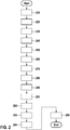
2 : Verfahren zur Erkennung einer Funktionsfähigkeit eines Umgebungssensors -
3a : Visualisierung zur Bestimmung mindestens eines Objektes in der Umgebung -
3b : Visualisierung der Umgebungsdaten mit semantischer Information
-
1a : Vehicle -
1b : Vehicle under supervision -
2 : Method for detecting the functionality of an environmental sensor -
3a : Visualization to determine at least one object in the area -
3b : Visualization of the environment data with semantic information
AusführungsbeispieleEmbodiments
In
In
In
In
Claims (15)
Priority Applications (4)
| Application Number | Priority Date | Filing Date | Title |
|---|---|---|---|
| DE102019206021.8A DE102019206021A1 (en) | 2019-04-26 | 2019-04-26 | Method for detecting the functionality of an environmental sensor, control unit and vehicle |
| CN202080029822.6A CN113710988B (en) | 2019-04-26 | 2020-03-25 | Method, control unit and vehicle for detecting the functional capability of an ambient sensor |
| US17/441,996 US20220172487A1 (en) | 2019-04-26 | 2020-03-25 | Method for detecting an operating capability of an environment sensor, control unit and vehicle |
| PCT/EP2020/058292 WO2020216559A1 (en) | 2019-04-26 | 2020-03-25 | Method for detecting a functionality of an environment sensor, control device and vehicle |
Applications Claiming Priority (1)
| Application Number | Priority Date | Filing Date | Title |
|---|---|---|---|
| DE102019206021.8A DE102019206021A1 (en) | 2019-04-26 | 2019-04-26 | Method for detecting the functionality of an environmental sensor, control unit and vehicle |
Publications (1)
| Publication Number | Publication Date |
|---|---|
| DE102019206021A1 true DE102019206021A1 (en) | 2020-10-29 |
Family
ID=69960654
Family Applications (1)
| Application Number | Title | Priority Date | Filing Date |
|---|---|---|---|
| DE102019206021.8A Pending DE102019206021A1 (en) | 2019-04-26 | 2019-04-26 | Method for detecting the functionality of an environmental sensor, control unit and vehicle |
Country Status (4)
| Country | Link |
|---|---|
| US (1) | US20220172487A1 (en) |
| CN (1) | CN113710988B (en) |
| DE (1) | DE102019206021A1 (en) |
| WO (1) | WO2020216559A1 (en) |
Cited By (9)
| Publication number | Priority date | Publication date | Assignee | Title |
|---|---|---|---|---|
| DE102021100792A1 (en) | 2021-01-15 | 2022-07-21 | Bayerische Motoren Werke Aktiengesellschaft | Method for calibrating an environment sensor of a vehicle, taking into account vehicle data from an external detection device, sensor system, vehicle and detection device |
| DE102021211197A1 (en) | 2021-10-05 | 2023-04-06 | Robert Bosch Gesellschaft mit beschränkter Haftung | Method and device for ensuring the functionality of a video system |
| DE102021212949A1 (en) | 2021-11-18 | 2023-05-25 | Robert Bosch Gesellschaft mit beschränkter Haftung | Method for determining a calibration quality of a sensor system of a vehicle, computer program, control unit and vehicle |
| DE102022205527A1 (en) | 2022-05-31 | 2023-11-30 | Siemens Mobility GmbH | Validation of a sensor unit of a rail vehicle for object localization |
| DE102022207725A1 (en) | 2022-07-27 | 2024-02-01 | Robert Bosch Gesellschaft mit beschränkter Haftung | Method and device for calibrating an infrastructure sensor system |
| DE102023201619A1 (en) * | 2023-02-22 | 2024-08-22 | Volkswagen Aktiengesellschaft | Method for mapping environmental markers |
| EP4428008A1 (en) * | 2023-03-09 | 2024-09-11 | Siemens Mobility GmbH | Automatic calibration of a sensor system for a rail vehicle |
| DE102023204214A1 (en) * | 2023-05-08 | 2024-11-14 | Siemens Mobility GmbH | Validation of an object recognition device of a rail vehicle |
| DE102023204912A1 (en) * | 2023-05-25 | 2024-11-28 | Siemens Mobility GmbH | Dynamic validation of a function of a sensor unit of a rail vehicle for object localization |
Families Citing this family (7)
| Publication number | Priority date | Publication date | Assignee | Title |
|---|---|---|---|---|
| US11126197B2 (en) * | 2018-11-19 | 2021-09-21 | Waymo Llc | Verification of iterative closest point alignments for autonomous vehicles |
| DE102019208735B4 (en) * | 2019-06-14 | 2021-12-23 | Volkswagen Aktiengesellschaft | Method for operating a driver assistance system for a vehicle and a driver assistance system for a vehicle |
| DE102019209292A1 (en) * | 2019-06-26 | 2020-12-31 | Robert Bosch Gmbh | Method for operating an environment sensor system of a vehicle and environment sensor system |
| US12399012B2 (en) * | 2020-02-21 | 2025-08-26 | Canon Kabushiki Kaisha | Information processing device, information processing method, and storage medium |
| US11614514B2 (en) * | 2020-03-27 | 2023-03-28 | Intel Corporation | Apparatus, system and method of generating radar perception data |
| US11524647B2 (en) * | 2020-12-03 | 2022-12-13 | Ford Global Technologies, Llc | Recalibration of radar sensor after airbag deployment |
| DE102023100734A1 (en) * | 2023-01-13 | 2024-07-18 | Bayerische Motoren Werke Aktiengesellschaft | CONTROL DEVICE AND CONTROL METHOD FOR CONTROLLING THE OPERATION OF AN ENVIRONMENT SENSOR OF A MOTOR VEHICLE |
Citations (5)
| Publication number | Priority date | Publication date | Assignee | Title |
|---|---|---|---|---|
| DE102009045709A1 (en) * | 2008-10-15 | 2010-09-23 | Continental Teves Ag & Co. Ohg | Improvement and validation of the position determination |
| DE102013113096A1 (en) * | 2012-12-19 | 2014-06-26 | Toyota Motor Engineering & Manufacturing North America, Inc. | Navigation of a road vehicle based on vertical elements |
| DE102015206605A1 (en) * | 2015-04-14 | 2016-10-20 | Continental Teves Ag & Co. Ohg | Calibration and monitoring of environmental sensors with the aid of highly accurate maps |
| US20180172454A1 (en) * | 2016-08-09 | 2018-06-21 | Nauto Global Limited | System and method for precision localization and mapping |
| DE102017214531A1 (en) * | 2017-08-21 | 2019-02-21 | Bayerische Motoren Werke Aktiengesellschaft | Method and device for operating a motor vehicle in an automated driving operation and motor vehicle |
Family Cites Families (11)
| Publication number | Priority date | Publication date | Assignee | Title |
|---|---|---|---|---|
| US7949486B2 (en) * | 2005-10-28 | 2011-05-24 | Hi-Key Limited | Method and apparatus for calibrating an image capturing device, and a method and apparatus for outputting image frames from sequentially captured image frames with compensation for image capture device offset |
| DE102010049093A1 (en) * | 2010-10-21 | 2012-04-26 | Gm Global Technology Operations Llc (N.D.Ges.D. Staates Delaware) | Method for operating at least one sensor of a vehicle and vehicle with at least one sensor |
| US9201424B1 (en) * | 2013-08-27 | 2015-12-01 | Google Inc. | Camera calibration using structure from motion techniques |
| JP6981095B2 (en) * | 2017-08-17 | 2021-12-15 | ソニーグループ株式会社 | Server equipment, recording methods, programs, and recording systems |
| JP7074438B2 (en) * | 2017-09-05 | 2022-05-24 | トヨタ自動車株式会社 | Vehicle position estimation device |
| KR102597409B1 (en) * | 2017-12-04 | 2023-11-02 | 현대자동차주식회사 | Method and apparatus for monitoring driver in system |
| KR102792151B1 (en) * | 2018-06-29 | 2025-04-08 | 소니 세미컨덕터 솔루션즈 가부시키가이샤 | Information processing device and information processing method, imaging device, computer program, information processing system, and mobile device |
| CN110163904B (en) * | 2018-09-11 | 2022-04-22 | 腾讯大地通途(北京)科技有限公司 | Object labeling method, movement control method, device, equipment and storage medium |
| DE102018007960A1 (en) * | 2018-10-09 | 2019-03-28 | Daimler Ag | Method for matching map material with a detected environment of a vehicle, control device configured to carry out such a method, and vehicle having such a control device |
| DE102020100685A1 (en) * | 2019-03-15 | 2020-09-17 | Nvidia Corporation | PREDICTION OF TEMPORARY INFORMATION IN AUTONOMOUS MACHINE APPLICATIONS |
| JP7199269B2 (en) * | 2019-03-20 | 2023-01-05 | 日立Astemo株式会社 | External sensing information processing device |
-
2019
- 2019-04-26 DE DE102019206021.8A patent/DE102019206021A1/en active Pending
-
2020
- 2020-03-25 US US17/441,996 patent/US20220172487A1/en not_active Abandoned
- 2020-03-25 WO PCT/EP2020/058292 patent/WO2020216559A1/en not_active Ceased
- 2020-03-25 CN CN202080029822.6A patent/CN113710988B/en active Active
Patent Citations (5)
| Publication number | Priority date | Publication date | Assignee | Title |
|---|---|---|---|---|
| DE102009045709A1 (en) * | 2008-10-15 | 2010-09-23 | Continental Teves Ag & Co. Ohg | Improvement and validation of the position determination |
| DE102013113096A1 (en) * | 2012-12-19 | 2014-06-26 | Toyota Motor Engineering & Manufacturing North America, Inc. | Navigation of a road vehicle based on vertical elements |
| DE102015206605A1 (en) * | 2015-04-14 | 2016-10-20 | Continental Teves Ag & Co. Ohg | Calibration and monitoring of environmental sensors with the aid of highly accurate maps |
| US20180172454A1 (en) * | 2016-08-09 | 2018-06-21 | Nauto Global Limited | System and method for precision localization and mapping |
| DE102017214531A1 (en) * | 2017-08-21 | 2019-02-21 | Bayerische Motoren Werke Aktiengesellschaft | Method and device for operating a motor vehicle in an automated driving operation and motor vehicle |
Cited By (10)
| Publication number | Priority date | Publication date | Assignee | Title |
|---|---|---|---|---|
| DE102021100792A1 (en) | 2021-01-15 | 2022-07-21 | Bayerische Motoren Werke Aktiengesellschaft | Method for calibrating an environment sensor of a vehicle, taking into account vehicle data from an external detection device, sensor system, vehicle and detection device |
| DE102021211197A1 (en) | 2021-10-05 | 2023-04-06 | Robert Bosch Gesellschaft mit beschränkter Haftung | Method and device for ensuring the functionality of a video system |
| DE102021212949A1 (en) | 2021-11-18 | 2023-05-25 | Robert Bosch Gesellschaft mit beschränkter Haftung | Method for determining a calibration quality of a sensor system of a vehicle, computer program, control unit and vehicle |
| DE102022205527A1 (en) | 2022-05-31 | 2023-11-30 | Siemens Mobility GmbH | Validation of a sensor unit of a rail vehicle for object localization |
| DE102022207725A1 (en) | 2022-07-27 | 2024-02-01 | Robert Bosch Gesellschaft mit beschränkter Haftung | Method and device for calibrating an infrastructure sensor system |
| DE102023201619A1 (en) * | 2023-02-22 | 2024-08-22 | Volkswagen Aktiengesellschaft | Method for mapping environmental markers |
| EP4428008A1 (en) * | 2023-03-09 | 2024-09-11 | Siemens Mobility GmbH | Automatic calibration of a sensor system for a rail vehicle |
| DE102023202129A1 (en) | 2023-03-09 | 2024-09-12 | Siemens Mobility GmbH | Automatic calibration of a sensor system for a rail vehicle |
| DE102023204214A1 (en) * | 2023-05-08 | 2024-11-14 | Siemens Mobility GmbH | Validation of an object recognition device of a rail vehicle |
| DE102023204912A1 (en) * | 2023-05-25 | 2024-11-28 | Siemens Mobility GmbH | Dynamic validation of a function of a sensor unit of a rail vehicle for object localization |
Also Published As
| Publication number | Publication date |
|---|---|
| WO2020216559A1 (en) | 2020-10-29 |
| US20220172487A1 (en) | 2022-06-02 |
| CN113710988B (en) | 2024-08-20 |
| CN113710988A (en) | 2021-11-26 |
Similar Documents
| Publication | Publication Date | Title |
|---|---|---|
| DE102019206021A1 (en) | Method for detecting the functionality of an environmental sensor, control unit and vehicle | |
| EP3584663B1 (en) | Method for automatic transverse guidance of a follow vehicle in a vehicle platoon | |
| DE102017125356B4 (en) | POSITION CALCULATION DEVICE | |
| DE102010005293B4 (en) | System and method for tracking path estimation using a sensor combination | |
| DE102016219455B4 (en) | Method and active infrastructure for checking a detection of the surroundings of a motor vehicle | |
| DE102018216009A1 (en) | APPARATUS FOR DETERMINING DISCONTINUED DRIVING, METHOD FOR DETERMINING DISCONTINUED DRIVING AND PROGRAM | |
| DE102016224329A1 (en) | Method and system for locating a vehicle | |
| DE102013206707A1 (en) | Method for checking an environment detection system of a vehicle | |
| DE102017107396A1 (en) | Test method and test device for driver assistance systems | |
| DE102017222017A1 (en) | Method and system for determining and providing a soil profile | |
| EP4163174B1 (en) | Method and device for the at least assisted lateral guidance of a motor vehicle | |
| WO2020126338A1 (en) | Method and system for determining a corrected trajectory of a vehicle | |
| DE102016207463A1 (en) | Method and device for operating at least one vehicle with respect to at least one passable object in the vicinity of the at least one vehicle | |
| DE102021204372A1 (en) | Orientation-based position determination of rail vehicles | |
| EP4296715A1 (en) | Method for determining an approximate object position of a dynamic object, computer program, device, and vehicle | |
| WO2023148339A1 (en) | Driving assistance system and method for operating a driving assistance system | |
| DE102021125136A1 (en) | DEVICE AND METHOD FOR PREDICTING THE TRAJECTORY OF A SURROUNDING VEHICLE | |
| DE102018211326A1 (en) | Method and device for determining a position of a vehicle | |
| DE102020211970A1 (en) | Method for controlling a vehicle | |
| DE102019132967A1 (en) | Method and device for determining a lane hypothesis | |
| DE102016220581A1 (en) | METHOD AND DEVICE FOR DETERMINING A ENVIRONMENTAL MODEL | |
| DE102017207441B4 (en) | Method for checking a digital environment map for a driver assistance system of a motor vehicle, computing device, driver assistance system and motor vehicle | |
| DE102021107385A1 (en) | Method for determining which lane a vehicle is in and system for operating a driver assistance function | |
| DE102021003792B4 (en) | Method for automated parking of a vehicle | |
| DE102017220483A1 (en) | Method and device for determining a position for a highly automated vehicle |
Legal Events
| Date | Code | Title | Description |
|---|---|---|---|
| R012 | Request for examination validly filed | ||
| R016 | Response to examination communication |