DE102019132121A1 - Drive train for an agricultural machine - Google Patents
Drive train for an agricultural machine Download PDFInfo
- Publication number
- DE102019132121A1 DE102019132121A1 DE102019132121.2A DE102019132121A DE102019132121A1 DE 102019132121 A1 DE102019132121 A1 DE 102019132121A1 DE 102019132121 A DE102019132121 A DE 102019132121A DE 102019132121 A1 DE102019132121 A1 DE 102019132121A1
- Authority
- DE
- Germany
- Prior art keywords
- intermediate gear
- drive train
- drive
- shaft
- output shaft
- Prior art date
- Legal status (The legal status is an assumption and is not a legal conclusion. Google has not performed a legal analysis and makes no representation as to the accuracy of the status listed.)
- Withdrawn
Links
Images


Classifications
-
- F—MECHANICAL ENGINEERING; LIGHTING; HEATING; WEAPONS; BLASTING
- F16—ENGINEERING ELEMENTS AND UNITS; GENERAL MEASURES FOR PRODUCING AND MAINTAINING EFFECTIVE FUNCTIONING OF MACHINES OR INSTALLATIONS; THERMAL INSULATION IN GENERAL
- F16H—GEARING
- F16H37/00—Combinations of mechanical gearings, not provided for in groups F16H1/00 - F16H35/00
- F16H37/02—Combinations of mechanical gearings, not provided for in groups F16H1/00 - F16H35/00 comprising essentially only toothed or friction gearings
- F16H37/021—Combinations of mechanical gearings, not provided for in groups F16H1/00 - F16H35/00 comprising essentially only toothed or friction gearings toothed gearing combined with continuously variable friction gearing
-
- B—PERFORMING OPERATIONS; TRANSPORTING
- B60—VEHICLES IN GENERAL
- B60K—ARRANGEMENT OR MOUNTING OF PROPULSION UNITS OR OF TRANSMISSIONS IN VEHICLES; ARRANGEMENT OR MOUNTING OF PLURAL DIVERSE PRIME-MOVERS IN VEHICLES; AUXILIARY DRIVES FOR VEHICLES; INSTRUMENTATION OR DASHBOARDS FOR VEHICLES; ARRANGEMENTS IN CONNECTION WITH COOLING, AIR INTAKE, GAS EXHAUST OR FUEL SUPPLY OF PROPULSION UNITS IN VEHICLES
- B60K17/00—Arrangement or mounting of transmissions in vehicles
- B60K17/04—Arrangement or mounting of transmissions in vehicles characterised by arrangement, location or kind of gearing
- B60K17/06—Arrangement or mounting of transmissions in vehicles characterised by arrangement, location or kind of gearing of change-speed gearing
- B60K17/08—Arrangement or mounting of transmissions in vehicles characterised by arrangement, location or kind of gearing of change-speed gearing of mechanical type
-
- F—MECHANICAL ENGINEERING; LIGHTING; HEATING; WEAPONS; BLASTING
- F16—ENGINEERING ELEMENTS AND UNITS; GENERAL MEASURES FOR PRODUCING AND MAINTAINING EFFECTIVE FUNCTIONING OF MACHINES OR INSTALLATIONS; THERMAL INSULATION IN GENERAL
- F16H—GEARING
- F16H47/00—Combinations of mechanical gearing with fluid clutches or fluid gearing
- F16H47/02—Combinations of mechanical gearing with fluid clutches or fluid gearing the fluid gearing being of the volumetric type
-
- F—MECHANICAL ENGINEERING; LIGHTING; HEATING; WEAPONS; BLASTING
- F16—ENGINEERING ELEMENTS AND UNITS; GENERAL MEASURES FOR PRODUCING AND MAINTAINING EFFECTIVE FUNCTIONING OF MACHINES OR INSTALLATIONS; THERMAL INSULATION IN GENERAL
- F16H—GEARING
- F16H57/00—General details of gearing
- F16H57/02—Gearboxes; Mounting gearing therein
- F16H57/028—Gearboxes; Mounting gearing therein characterised by means for reducing vibration or noise
-
- B—PERFORMING OPERATIONS; TRANSPORTING
- B60—VEHICLES IN GENERAL
- B60K—ARRANGEMENT OR MOUNTING OF PROPULSION UNITS OR OF TRANSMISSIONS IN VEHICLES; ARRANGEMENT OR MOUNTING OF PLURAL DIVERSE PRIME-MOVERS IN VEHICLES; AUXILIARY DRIVES FOR VEHICLES; INSTRUMENTATION OR DASHBOARDS FOR VEHICLES; ARRANGEMENTS IN CONNECTION WITH COOLING, AIR INTAKE, GAS EXHAUST OR FUEL SUPPLY OF PROPULSION UNITS IN VEHICLES
- B60K5/00—Arrangement or mounting of internal-combustion or jet-propulsion units
- B60K5/02—Arrangement or mounting of internal-combustion or jet-propulsion units with the engine main axis, e.g. crankshaft axis, substantially in or parallel to the longitudinal centre line of the vehicle
-
- B—PERFORMING OPERATIONS; TRANSPORTING
- B60—VEHICLES IN GENERAL
- B60Y—INDEXING SCHEME RELATING TO ASPECTS CROSS-CUTTING VEHICLE TECHNOLOGY
- B60Y2200/00—Type of vehicle
- B60Y2200/20—Off-Road Vehicles
- B60Y2200/22—Agricultural vehicles
-
- B—PERFORMING OPERATIONS; TRANSPORTING
- B60—VEHICLES IN GENERAL
- B60Y—INDEXING SCHEME RELATING TO ASPECTS CROSS-CUTTING VEHICLE TECHNOLOGY
- B60Y2200/00—Type of vehicle
- B60Y2200/20—Off-Road Vehicles
- B60Y2200/22—Agricultural vehicles
- B60Y2200/221—Tractors
-
- B—PERFORMING OPERATIONS; TRANSPORTING
- B60—VEHICLES IN GENERAL
- B60Y—INDEXING SCHEME RELATING TO ASPECTS CROSS-CUTTING VEHICLE TECHNOLOGY
- B60Y2400/00—Special features of vehicle units
- B60Y2400/70—Gearings
- B60Y2400/72—Continous variable transmissions [CVT]
-
- F—MECHANICAL ENGINEERING; LIGHTING; HEATING; WEAPONS; BLASTING
- F16—ENGINEERING ELEMENTS AND UNITS; GENERAL MEASURES FOR PRODUCING AND MAINTAINING EFFECTIVE FUNCTIONING OF MACHINES OR INSTALLATIONS; THERMAL INSULATION IN GENERAL
- F16H—GEARING
- F16H57/00—General details of gearing
- F16H57/02—Gearboxes; Mounting gearing therein
- F16H2057/02039—Gearboxes for particular applications
- F16H2057/02043—Gearboxes for particular applications for vehicle transmissions
- F16H2057/02056—Gearboxes for particular applications for vehicle transmissions for utility vehicles, e.g. tractors or agricultural machines
Landscapes
- Engineering & Computer Science (AREA)
- General Engineering & Computer Science (AREA)
- Mechanical Engineering (AREA)
- Chemical & Material Sciences (AREA)
- Combustion & Propulsion (AREA)
- Transportation (AREA)
- Motor Power Transmission Devices (AREA)
Abstract
Die vorliegende Erfindung betrifft einen Antriebsstrang (7) für eine landwirtschaftliche Arbeitsmaschine (1, 2), wobei der Antriebsstrang (7) einen Antriebsmotor (8) mit einer Abtriebswelle (12) und einem Motorgehäuse (11) sowie ein stufenloses Getriebe (9) mit einem Getriebegehäuse (13), welches von dem Antriebsmotor (8) über eine Eingangswelle (14) angetrieben ist, umfasst, wobei zwischen dem Antriebsmotor (8) und dem stufenloses Getriebe (9) ein Zwischengetriebemodul (10) mit einem separaten Gehäuse (16) angeordnet ist, welches an dem Motorgehäuse (11) und/oder dem Getriebegehäuse (13) angebunden ist, und dass das Zwischengetriebemodul (10) eine Eingangswelle (17) und eine Ausgangswelle (18) aufweist, wobei die Eingangswelle (17) des Zwischengetriebemoduls (10) und die Abtriebswelle (12) des Antriebsmotors (8) und/oder die Ausgangswelle (18) des Zwischengetriebemoduls (10) und die Eingangswelle (14) des stufenloses Getriebes (9) koaxial angeordnet sind.

Description
Die vorliegende Erfindung betrifft einen Antriebsstrang für eine landwirtschaftliche Arbeitsmaschine gemäß dem Oberbegriff des Anspruches 1. Weiterhin betrifft die Erfindung eine landwirtschaftliche Arbeitsmaschine, insbesondere einen Traktor.The present invention relates to a drive train for an agricultural work machine according to the preamble of
Aus der
Der Antriebsstrang landwirtschaftlicher Arbeitsmaschinen variiert in Abhängigkeit von den Leistungsklassen der Antriebsmotoren, die für verschiedene Typen von Arbeitsmaschinen zur Anwendung kommen, während das stufenlose Getriebe oftmals für mehrere Typen von Arbeitsmaschinen gleich ist. So können beispielsweise als Traktoren ausgeführte landwirtschaftliche Arbeitsmaschinen unterschiedlichen Typs mit in ihrer abgegebenen Leistung unterschiedlichen Antriebsmotoren ausgeführt sein, während das zum Einsatz kommende stufenlose Getriebe das gleiche ist.The drive train of agricultural work machines varies depending on the power classes of the drive motors that are used for different types of work machines, while the continuously variable transmission is often the same for several types of work machines. For example, agricultural work machines of different types designed as tractors can be designed with different drive motors in terms of their output, while the continuously variable transmission used is the same.
Ausgehend vom vorstehend genannten Stand der Technik liegt der Erfindung die Aufgabe zugrunde, einen Antriebsstrang für eine landwirtschaftliche Arbeitsmaschine bereitzustellen, welcher sich durch eine höhere Flexibilität bei der Anpassung von vom Antriebsmotor auf das stufenlose Getriebe zu übertragenden Drehzahlen und Drehmomenten auszeichnet.Starting from the prior art mentioned above, the invention is based on the object of providing a drive train for an agricultural work machine, which is characterized by greater flexibility in the adaptation of the speeds and torques to be transmitted from the drive motor to the continuously variable transmission.
Diese Aufgabe wird erfindungsgemäß durch einen Antriebsstrang mit den Merkmalen des Anspruches 1 gelöst. Vorteilhafte Weiterbildungen sind Gegenstand der Unteransprüche.According to the invention, this object is achieved by a drive train with the features of
Gemäß dem Anspruch 1 wird ein Antriebsstrang für eine landwirtschaftliche Arbeitsmaschine vorgeschlagen, wobei der Antriebsstrang einen Antriebsmotor mit einer Abtriebswelle und einem Motorgehäuse sowie ein stufenloses Getriebe mit einem Getriebegehäuse, welches von dem Antriebsmotor über eine Eingangswelle angetrieben ist, umfasst, wobei zwischen dem Antriebsmotor und dem stufenloses Getriebe ein Zwischengetriebemodul mit einem separaten Gehäuse angeordnet ist, welches an dem Motorgehäuse und/oder dem Getriebegehäuse angebunden ist, und dass das Zwischengetriebemodul eine Eingangswelle und eine Ausgangswelle aufweist, wobei die Eingangswelle des Zwischengetriebemoduls und die Abtriebswelle des Antriebsmotor und/oder die Ausgangswelle des Zwischengetriebemoduls und die Eingangswelle des stufenloses Getriebes koaxial angeordnet sind. Ein derartig aufgebauter Antriebsstrang hat insbesondere die Effekte, dass der Getriebebaukasten, d.h. die Anzahl von verschiedenen Getriebetypen, für die Darstellung unterschiedlicher Leistungsbereiche reduziert werden kann und dass durch die Reduzierung des Getriebebaukastens der Bauraumbedarf für die gesamte Antriebsstrangstruktur verringert werden kann. Das Zwischengetriebemodul ist hinsichtlich seines Gesamtübersetzungsverhältnisses an unterschiedliche Leistungsklassen von Antriebsmotoren und/oder stufenlosen Getrieben anpassbar. Die wahlweise Verbindung des Zwischengetriebemoduls mit dem Motorgehäuse oder mit dem Getriebegehäuse, insbesondere durch Anflanschen mittels einer Schraubverbindung, trägt zu einer besseren Integrationsfähigkeit in den Antriebsstrang bei. So kann der Antriebsmotor sich im Wesentlichen oberhalb eines Fahrzeugrahmens der Arbeitsmaschine erstreckend angeordnet sein, während das stufenlose Getriebe im Wesentlichen zwischen dem Fahrzeugrahmen positioniert ist. Durch das koaxial zur Abtriebswelle und/od er zur Eingangswelle des stufenlosen Getriebes angeordnete Zwischengetriebemodul kann der aus der vertikal versetzten Anordnung von Antriebsmotor und stufenlosem Getriebe resultierende vertikale Versatz zwischen der Abtriebswelle des Antriebsmotors und der Eingangswelle des stufenlosen Getriebes zumindest teilweise ausgeglichen werden. Denkbar ist auch eine Blockbauweise, bei welcher das Gehäuse des Zwischengetriebemoduls mit dem Motorgehäuse und dem Getriebegehäuse verbunden ist.According to
Bevorzugt kann das Zwischengetriebemodul als ein Pumpenverteilergetriebe ausgeführt sein. Neben der Anpassung von Drehzahl und Drehmoment, welche vom Antriebsmotor auf das stufenlose Getriebe übertragen werden, kann das Zwischengetriebemodul zugleich dem Antrieb von zumindest einer hydraulischen Antriebsvorrichtung dienen.The intermediate gear module can preferably be designed as a pump transfer gear. In addition to adapting the speed and torque, which are transmitted from the drive motor to the continuously variable transmission, the intermediate transmission module can also serve to drive at least one hydraulic drive device.
Vorteilhaft ist es, wenn in den Antriebsstrang ein Torsionsdämpfer zwischen dem Antriebsmotor und dem stufenlosen Getriebe integriert ist. Der Torsionsdämpfer kann als Schwingungsdämpfer hinter dem Antriebsmotor zum Einsatz kommen, wenn in dem Antriebsstrang keine Trenn- und Anfahrkupplung vorgesehen ist. Mit dem Einsatz des Torsionsdämpfers können sowohl Drehmomentspitzen des Antriebsmotors als auch Laufunruhen vom Antriebsstrang oder von gekoppelten Arbeitsgeräten ferngehalten werden. Insbesondere bei einer koaxialen Anordnung von Abtriebswelle des Antriebsmotors und Eingangswelle des Zwischengetriebemoduls sind Torsionsschwingungen vernachlässigbar.It is advantageous if a torsional damper is integrated in the drive train between the drive motor and the continuously variable transmission. The torsional damper can be used as a vibration damper behind the drive motor can be used if no separating and starting clutch is provided in the drive train. With the use of the torsion damper, both torque peaks of the drive motor and uneven running can be kept away from the drive train or from coupled work equipment. In particular with a coaxial arrangement of the output shaft of the drive motor and the input shaft of the intermediate gear module, torsional vibrations are negligible.
Gemäß einer bevorzugten Weiterbildung können die Eingangswelle und die Ausgangswelle des Zwischengetriebemoduls axial versetzt zueinander angeordnet sein. Hierdurch kann ebenfalls zu einer Bauraumreduzierung beigetragen werden.According to a preferred development, the input shaft and the output shaft of the intermediate gear module can be arranged axially offset from one another. This can also contribute to a reduction in installation space.
Insbesondere kann das Zwischengetriebemodul mit der Abtriebswelle des Antriebsmotors oder der Eingangswelle des stufenlosen Getriebes durch eine Gelenkwelle verbunden sein. Die vertikal versetzte Anordnung der Eingangswelle und der Ausgangswelle des Zwischengetriebemoduls trägt dazu bei, axialen Bauraum für die Gelenkwelle einzusparen. Insbesondere ist der teilweise Ausgleich des vertikalen Versatzes zwischen der Abtriebswelle des Antriebsmotors und der Eingangswelle des stufenlosen Getriebes durch das Zwischengetriebeelement vorteilhaft, um den Beugewinkel der Gelenkwelle gering zu halten, wodurch ein größtmöglicher Wirkungsgrad bei der Drehmomentübertragung erreicht werden kann.In particular, the intermediate gear module can be connected to the output shaft of the drive motor or the input shaft of the continuously variable transmission by a cardan shaft. The vertically offset arrangement of the input shaft and the output shaft of the intermediate gear module helps to save axial installation space for the cardan shaft. In particular, the partial compensation of the vertical offset between the output shaft of the drive motor and the input shaft of the continuously variable transmission by the intermediate gear element is advantageous in order to keep the articulation angle of the propeller shaft low, whereby the greatest possible efficiency in torque transmission can be achieved.
Einem weiteren Gedanken der Erfindung gemäß kann das Zwischengetriebemodul als Stirnradgetriebe ausgeführt sein. Stirnradgetriebe zeichnen sich durch eine einfache Bauweise und hohe Robustheit aus.According to a further idea of the invention, the intermediate gear module can be designed as a spur gear. Spur gears are characterized by a simple design and high level of robustness.
Dabei kann das Zwischengetriebemodul eine erste Zahnradstufe mit einem ersten auf der Eingangswelle angeordneten Zahnradelement aufweisen, welches mit zumindest einem auf zumindest einer achsparallelen Welle angeordneten zweiten Zahnradelement kämmt. Mittels der ersten Zahnradstufe kann ein Übersetzungsverhältnis vorgegeben werden, welches an die Größenordnung der zu übertragenden Drehzahl und des zu übertragenden Drehmoments zwischen dem zum Einsatz kommenden Antriebsmotor sowie dem nachgeordneten stufenlosen Getriebe angepasst ist. Dadurch kann berücksichtigt werden, dass der Antriebsmotor ein höheres Drehmoment bereitstellen kann als das stufenlose Getriebe dauerhaft aufnehmen kann. Eine Schädigung des stufenlosen Getriebes kann somit vermieden werden.The intermediate gear module can have a first gear stage with a first gear element arranged on the input shaft, which meshes with at least one second gear element arranged on at least one axially parallel shaft. By means of the first gear stage, a transmission ratio can be specified which is adapted to the magnitude of the speed to be transmitted and the torque to be transmitted between the drive motor used and the downstream continuously variable transmission. This makes it possible to take into account that the drive motor can provide a higher torque than the continuously variable transmission can permanently absorb. Damage to the continuously variable transmission can thus be avoided.
Insbesondere kann die zumindest eine Welle eine Abtriebswelle des Zwischengetriebemoduls bilden, an die eine hydraulische Antriebsvorrichtung anschließbar ist. Die hydraulische Antriebsvorrichtung kann insbesondere als Hydraulikpumpe ausgeführt sein. Die Hydraulikpumpe ist dadurch unabhängig vom stufenlosen Getriebe antreibbar. Die Antriebsdrehzahl der Hydraulikpumpe resultiert aus dem Übersetzungsverhältnis der ersten Zahnradstufe. Die zumindest eine Welle kann alternativ die Ausgangswelle des Zwischengetriebemoduls bilden.In particular, the at least one shaft can form an output shaft of the intermediate gear module to which a hydraulic drive device can be connected. The hydraulic drive device can in particular be designed as a hydraulic pump. The hydraulic pump can thus be driven independently of the continuously variable transmission. The drive speed of the hydraulic pump results from the transmission ratio of the first gear stage. The at least one shaft can alternatively form the output shaft of the intermediate gear module.
Gemäß einer bevorzugten Weiterbildung kann die erste Zahnradstufe ein drittes Zahnradelement aufweisen, welches mit dem ersten Zahnradelement kämmt. Das auf einer weiteren achsparallelen Welle angeordnete dritte Zahnradelement kann dem Antrieb einer weiteren, als hydraulische Antriebsvorrichtung ausgeführten, Hydraulikpumpe dienen.According to a preferred development, the first gear stage can have a third gear element which meshes with the first gear element. The third gear element arranged on a further axially parallel shaft can serve to drive a further hydraulic pump designed as a hydraulic drive device.
Weiterhin kann auf der zumindest einen Welle ein erstes Zahnradelement einer zweiten Zahnradstufe angeordnet sein, welches mit einem zweiten Zahnradelement der zweiten Zahnradstufe kämmt, das auf der Ausgangswelle des Zwischengetriebemoduls angeordnet ist.Furthermore, a first gear element of a second gear stage can be arranged on the at least one shaft which meshes with a second gear element of the second gear stage which is arranged on the output shaft of the intermediate gear module.
Vorteilhaft ist es, wenn der Torsionsdämpfer von einer Lagerung des ersten Zahnradelementes der ersten Zahnradstufe des Zwischengetriebemoduls aufgenommen ist. Bevorzugt sind dabei die Abtriebswelle des Antriebsmotors und die Eingangswelle des Zwischengetriebemoduls koaxial angeordnet.It is advantageous if the torsional damper is accommodated in a mounting of the first gearwheel element of the first gearwheel stage of the intermediate gear module. The output shaft of the drive motor and the input shaft of the intermediate gear module are preferably arranged coaxially.
Des Weiteren wird die eingangs gestellte Aufgabe durch eine landwirtschaftliche Arbeitsmaschine mit einem Antriebsstrang nach einem der Ansprüche 1 bis 10 gelöst.Furthermore, the object set out at the beginning is achieved by an agricultural work machine with a drive train according to one of
Die vorliegende Erfindung wird nachstehend anhand von in den Zeichnungen dargestellten Ausführungsbeispielen näher erläutert.The present invention is explained in more detail below with reference to the exemplary embodiments shown in the drawings.
Es zeigen:
-
1 eine schematische Seitenansicht einer landwirtschaftlichen Arbeitsmaschine; -
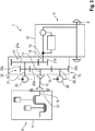
2 eine schematische Darstellung eines Antriebsstrangs der Arbeitsmaschine; -
3 eine schematische Darstellung einer weiteren Ausführungsform eines Antriebsstrangs der Arbeitsmaschine.
-
1 a schematic side view of an agricultural work machine; -
2 a schematic representation of a drive train of the work machine; -
3rd a schematic representation of a further embodiment of a drive train of the work machine.
In
In
In den Antriebsstrang
Das Zwischengetriebemodul
Auf der Eingangswelle
Die zweite Zahnradstufe
In
Zwischen der Abtriebswelle
Das Zwischengetriebemodul
Wie aus den schematischen Darstellungen in den
Gemäß einer nicht dargestellten Ausführungsform, kann vorgesehen sein, dass sowohl die Abtriebswelle
Denkbar ist auch eine Blockbauweise von Antriebsmotor
BezugszeichenlisteList of reference symbols
- 11
- ArbeitsmaschineWorking machine
- 22
- Traktortractor
- 33
- VorderradFront wheel
- 44th
- HinterradRear wheel
- 55
- VorderachseFront axle
- 66th
- HinterachseRear axle
- 77th
- AntriebsstrangPowertrain
- 88th
- AntriebsmotorDrive motor
- 99
- Stufenloses GetriebeStepless gear
- 1010
- ZwischengetriebemodulIntermediate gear module
- 1111
- MotorgehäuseMotor housing
- 1212th
- AbtriebswelleOutput shaft
- 1313th
- GetriebegehäuseGear housing
- 1414th
- EingangswelleInput shaft
- 1515th
- GelenkwellePTO shaft
- 1616
- Gehäusecasing
- 1717th
- EingangswelleInput shaft
- 1818th
- AusgangswelleOutput shaft
- 1919th
- TorsionsdämpferTorsional damper
- 2020th
- Erste ZahnradstufeFirst gear stage
- 20a20a
- Erstes ZahnradelementFirst gear element
- 20b20b
- Zweites ZahnradelementSecond gear element
- 20c20c
- Drittes ZahnradelementThird gear element
- 2121
- Wellewave
- 2222nd
- Wellewave
- 2323
- AbtriebswelleOutput shaft
- 2424
- AbtriebswelleOutput shaft
- 2525th
- Hydraulische AntriebsvorrichtungHydraulic drive device
- 2626th
- Hydraulische AntriebsvorrichtungHydraulic drive device
- 2727
- Zweite Zahnradstufe Second gear stage
- 27a27a
- Erstes ZahnradelementFirst gear element
- 27b27b
- Zweites ZahnradelementSecond gear element
ZITATE ENTHALTEN IN DER BESCHREIBUNGQUOTES INCLUDED IN THE DESCRIPTION
Diese Liste der vom Anmelder aufgeführten Dokumente wurde automatisiert erzeugt und ist ausschließlich zur besseren Information des Lesers aufgenommen. Die Liste ist nicht Bestandteil der deutschen Patent- bzw. Gebrauchsmusteranmeldung. Das DPMA übernimmt keinerlei Haftung für etwaige Fehler oder Auslassungen.This list of the documents listed by the applicant was generated automatically and is included solely for the better information of the reader. The list is not part of the German patent or utility model application. The DPMA assumes no liability for any errors or omissions.
Zitierte PatentliteraturPatent literature cited
- DE 102011102210 A1 [0002]DE 102011102210 A1 [0002]
Claims (11)
Priority Applications (2)
| Application Number | Priority Date | Filing Date | Title |
|---|---|---|---|
| DE102019132121.2A DE102019132121A1 (en) | 2019-11-27 | 2019-11-27 | Drive train for an agricultural machine |
| EP20194762.9A EP3831635A1 (en) | 2019-11-27 | 2020-09-07 | Power train for an agricultural working machine |
Applications Claiming Priority (1)
| Application Number | Priority Date | Filing Date | Title |
|---|---|---|---|
| DE102019132121.2A DE102019132121A1 (en) | 2019-11-27 | 2019-11-27 | Drive train for an agricultural machine |
Publications (1)
| Publication Number | Publication Date |
|---|---|
| DE102019132121A1 true DE102019132121A1 (en) | 2021-05-27 |
Family
ID=72422107
Family Applications (1)
| Application Number | Title | Priority Date | Filing Date |
|---|---|---|---|
| DE102019132121.2A Withdrawn DE102019132121A1 (en) | 2019-11-27 | 2019-11-27 | Drive train for an agricultural machine |
Country Status (2)
| Country | Link |
|---|---|
| EP (1) | EP3831635A1 (en) |
| DE (1) | DE102019132121A1 (en) |
Cited By (1)
| Publication number | Priority date | Publication date | Assignee | Title |
|---|---|---|---|---|
| DE102021206962A1 (en) | 2021-07-02 | 2023-01-05 | Zf Friedrichshafen Ag | Transmission arrangement with two friction clutches for a vehicle and drive train and vehicle with the transmission arrangement |
Family Cites Families (4)
| Publication number | Priority date | Publication date | Assignee | Title |
|---|---|---|---|---|
| US20110082002A1 (en) * | 2009-10-06 | 2011-04-07 | International Truck Intellectual Property Company, Llc | Continuously Variable Rear Axle |
| JP5788158B2 (en) * | 2010-09-27 | 2015-09-30 | ヤンマー株式会社 | Drive system control device for work vehicle |
| DE102011102210A1 (en) | 2010-12-30 | 2012-07-05 | Hytrac Gmbh | Power split transmission |
| DE102014003203A1 (en) * | 2014-03-06 | 2015-09-10 | Liebherr-Mining Equipment Colmar Sas | Work machine, in particular dump truck or truck |
-
2019
- 2019-11-27 DE DE102019132121.2A patent/DE102019132121A1/en not_active Withdrawn
-
2020
- 2020-09-07 EP EP20194762.9A patent/EP3831635A1/en active Pending
Cited By (1)
| Publication number | Priority date | Publication date | Assignee | Title |
|---|---|---|---|---|
| DE102021206962A1 (en) | 2021-07-02 | 2023-01-05 | Zf Friedrichshafen Ag | Transmission arrangement with two friction clutches for a vehicle and drive train and vehicle with the transmission arrangement |
Also Published As
| Publication number | Publication date |
|---|---|
| EP3831635A1 (en) | 2021-06-09 |
Similar Documents
| Publication | Publication Date | Title |
|---|---|---|
| DE60212220T2 (en) | Motion transmission device for hybrid vehicles | |
| DE102013002586A1 (en) | Hybrid drive device for motor car, has clutch that is set to interconnect the shaft sections of intermediate shaft which is provided to connect input shaft with sun gears of planetary gears | |
| DE102007059321A1 (en) | Power split transmission | |
| DE102006041159B4 (en) | Hybrid drive device | |
| DE102011011867A1 (en) | Transmission for a rail vehicle powertrain | |
| EP3647097A1 (en) | Motor vehicle drive | |
| DE102007000619A1 (en) | Hydrostatic-mechanical power split transmission for use in agricultural vehicle i.e. agricultural tractor, has switching unit selectively connecting hydraulic power sector to sun gear in summation transmission over two transmission stages | |
| DE102015206160A1 (en) | Powertrain for an agricultural work vehicle | |
| DE102011087163A1 (en) | Transmission of a motor vehicle with PTO | |
| DE102018204912A1 (en) | PTO arrangement | |
| DE102015219462A1 (en) | Hybrid powertrain for a motor vehicle | |
| DE102019132121A1 (en) | Drive train for an agricultural machine | |
| DE102015208756A1 (en) | Transmission device for a hybrid drive system | |
| EP2248698A1 (en) | Powertrain for a commercial vehicle comprising an infinitely adjustable gearbox | |
| DE102008044035B4 (en) | A four-wheel hybrid powertrain for a motor vehicle and method of operating the hybrid powertrain | |
| DE102014220028B4 (en) | Transmission device with power split | |
| DE102008061061A1 (en) | Gear arrangement for a vehicle | |
| DE102016005804B4 (en) | Drive device for a motor vehicle and method for operating a drive device | |
| DE102018215454A1 (en) | Hydraulic actuation system of a transmission with a vane pump | |
| DE102011118111A1 (en) | Drivetrain for driving internal combustion engine of lorry, has hydraulic pump conveying hydraulic medium and driven by axle differential, which includes plate wheel for introducing rotational torque of drive motor into axle differential | |
| DE102009002806A1 (en) | Powertrain of a motor vehicle | |
| DE102021210551A1 (en) | DROPBOX TRANSMISSION IN A REDUCED SPACE | |
| DE102024204852B3 (en) | Powershift group transmission for a work machine and agricultural vehicle | |
| DE102020104498B4 (en) | Motor vehicle with a center differential | |
| DE102021208645B4 (en) | Drivetrain for a vehicle |
Legal Events
| Date | Code | Title | Description |
|---|---|---|---|
| R082 | Change of representative |
Representative=s name: PATENT- UND RECHTSANWALTSKANZLEI DEKKER PARTGM, DE |
|
| R119 | Application deemed withdrawn, or ip right lapsed, due to non-payment of renewal fee |