DE102019131653B4 - Conductor connection terminal - Google Patents
Conductor connection terminal Download PDFInfo
- Publication number
- DE102019131653B4 DE102019131653B4 DE102019131653.7A DE102019131653A DE102019131653B4 DE 102019131653 B4 DE102019131653 B4 DE 102019131653B4 DE 102019131653 A DE102019131653 A DE 102019131653A DE 102019131653 B4 DE102019131653 B4 DE 102019131653B4
- Authority
- DE
- Germany
- Prior art keywords
- connection terminal
- conductor
- busbar
- conductor connection
- clamping
- Prior art date
- Legal status (The legal status is an assumption and is not a legal conclusion. Google has not performed a legal analysis and makes no representation as to the accuracy of the status listed.)
- Active
Links
Images

Classifications
-
- H—ELECTRICITY
- H01—ELECTRIC ELEMENTS
- H01R—ELECTRICALLY-CONDUCTIVE CONNECTIONS; STRUCTURAL ASSOCIATIONS OF A PLURALITY OF MUTUALLY-INSULATED ELECTRICAL CONNECTING ELEMENTS; COUPLING DEVICES; CURRENT COLLECTORS
- H01R4/00—Electrically-conductive connections between two or more conductive members in direct contact, i.e. touching one another; Means for effecting or maintaining such contact; Electrically-conductive connections having two or more spaced connecting locations for conductors and using contact members penetrating insulation
- H01R4/28—Clamped connections, spring connections
- H01R4/48—Clamped connections, spring connections utilising a spring, clip, or other resilient member
-
- H—ELECTRICITY
- H01—ELECTRIC ELEMENTS
- H01R—ELECTRICALLY-CONDUCTIVE CONNECTIONS; STRUCTURAL ASSOCIATIONS OF A PLURALITY OF MUTUALLY-INSULATED ELECTRICAL CONNECTING ELEMENTS; COUPLING DEVICES; CURRENT COLLECTORS
- H01R13/00—Details of coupling devices of the kinds covered by groups H01R12/70 or H01R24/00 - H01R33/00
- H01R13/46—Bases; Cases
- H01R13/502—Bases; Cases composed of different pieces
-
- H—ELECTRICITY
- H01—ELECTRIC ELEMENTS
- H01R—ELECTRICALLY-CONDUCTIVE CONNECTIONS; STRUCTURAL ASSOCIATIONS OF A PLURALITY OF MUTUALLY-INSULATED ELECTRICAL CONNECTING ELEMENTS; COUPLING DEVICES; CURRENT COLLECTORS
- H01R25/00—Coupling parts adapted for simultaneous co-operation with two or more identical counterparts, e.g. for distributing energy to two or more circuits
- H01R25/14—Rails or bus-bars constructed so that the counterparts can be connected thereto at any point along their length
-
- H—ELECTRICITY
- H01—ELECTRIC ELEMENTS
- H01R—ELECTRICALLY-CONDUCTIVE CONNECTIONS; STRUCTURAL ASSOCIATIONS OF A PLURALITY OF MUTUALLY-INSULATED ELECTRICAL CONNECTING ELEMENTS; COUPLING DEVICES; CURRENT COLLECTORS
- H01R4/00—Electrically-conductive connections between two or more conductive members in direct contact, i.e. touching one another; Means for effecting or maintaining such contact; Electrically-conductive connections having two or more spaced connecting locations for conductors and using contact members penetrating insulation
- H01R4/28—Clamped connections, spring connections
- H01R4/48—Clamped connections, spring connections utilising a spring, clip, or other resilient member
- H01R4/4809—Clamped connections, spring connections utilising a spring, clip, or other resilient member using a leaf spring to bias the conductor toward the busbar
- H01R4/48185—Clamped connections, spring connections utilising a spring, clip, or other resilient member using a leaf spring to bias the conductor toward the busbar adapted for axial insertion of a wire end
- H01R4/4819—Clamped connections, spring connections utilising a spring, clip, or other resilient member using a leaf spring to bias the conductor toward the busbar adapted for axial insertion of a wire end the spring shape allowing insertion of the conductor end when the spring is unbiased
- H01R4/4821—Single-blade spring
-
- H—ELECTRICITY
- H01—ELECTRIC ELEMENTS
- H01R—ELECTRICALLY-CONDUCTIVE CONNECTIONS; STRUCTURAL ASSOCIATIONS OF A PLURALITY OF MUTUALLY-INSULATED ELECTRICAL CONNECTING ELEMENTS; COUPLING DEVICES; CURRENT COLLECTORS
- H01R4/00—Electrically-conductive connections between two or more conductive members in direct contact, i.e. touching one another; Means for effecting or maintaining such contact; Electrically-conductive connections having two or more spaced connecting locations for conductors and using contact members penetrating insulation
- H01R4/28—Clamped connections, spring connections
- H01R4/48—Clamped connections, spring connections utilising a spring, clip, or other resilient member
- H01R4/4809—Clamped connections, spring connections utilising a spring, clip, or other resilient member using a leaf spring to bias the conductor toward the busbar
- H01R4/4828—Spring-activating arrangements mounted on or integrally formed with the spring housing
- H01R4/483—Pivoting arrangements, e.g. lever pushing on the spring
-
- H—ELECTRICITY
- H01—ELECTRIC ELEMENTS
- H01R—ELECTRICALLY-CONDUCTIVE CONNECTIONS; STRUCTURAL ASSOCIATIONS OF A PLURALITY OF MUTUALLY-INSULATED ELECTRICAL CONNECTING ELEMENTS; COUPLING DEVICES; CURRENT COLLECTORS
- H01R4/00—Electrically-conductive connections between two or more conductive members in direct contact, i.e. touching one another; Means for effecting or maintaining such contact; Electrically-conductive connections having two or more spaced connecting locations for conductors and using contact members penetrating insulation
- H01R4/28—Clamped connections, spring connections
- H01R4/48—Clamped connections, spring connections utilising a spring, clip, or other resilient member
- H01R4/4854—Clamped connections, spring connections utilising a spring, clip, or other resilient member using a wire spring
-
- H—ELECTRICITY
- H01—ELECTRIC ELEMENTS
- H01R—ELECTRICALLY-CONDUCTIVE CONNECTIONS; STRUCTURAL ASSOCIATIONS OF A PLURALITY OF MUTUALLY-INSULATED ELECTRICAL CONNECTING ELEMENTS; COUPLING DEVICES; CURRENT COLLECTORS
- H01R9/00—Structural associations of a plurality of mutually-insulated electrical connecting elements, e.g. terminal strips or terminal blocks; Terminals or binding posts mounted upon a base or in a case; Bases therefor
- H01R9/22—Bases, e.g. strip, block, panel
- H01R9/24—Terminal blocks
- H01R9/2416—Means for guiding or retaining wires or cables connected to terminal blocks
-
- H—ELECTRICITY
- H01—ELECTRIC ELEMENTS
- H01R—ELECTRICALLY-CONDUCTIVE CONNECTIONS; STRUCTURAL ASSOCIATIONS OF A PLURALITY OF MUTUALLY-INSULATED ELECTRICAL CONNECTING ELEMENTS; COUPLING DEVICES; CURRENT COLLECTORS
- H01R4/00—Electrically-conductive connections between two or more conductive members in direct contact, i.e. touching one another; Means for effecting or maintaining such contact; Electrically-conductive connections having two or more spaced connecting locations for conductors and using contact members penetrating insulation
- H01R4/28—Clamped connections, spring connections
- H01R4/48—Clamped connections, spring connections utilising a spring, clip, or other resilient member
- H01R4/4809—Clamped connections, spring connections utilising a spring, clip, or other resilient member using a leaf spring to bias the conductor toward the busbar
- H01R4/4846—Busbar details
-
- H—ELECTRICITY
- H01—ELECTRIC ELEMENTS
- H01R—ELECTRICALLY-CONDUCTIVE CONNECTIONS; STRUCTURAL ASSOCIATIONS OF A PLURALITY OF MUTUALLY-INSULATED ELECTRICAL CONNECTING ELEMENTS; COUPLING DEVICES; CURRENT COLLECTORS
- H01R9/00—Structural associations of a plurality of mutually-insulated electrical connecting elements, e.g. terminal strips or terminal blocks; Terminals or binding posts mounted upon a base or in a case; Bases therefor
- H01R9/22—Bases, e.g. strip, block, panel
- H01R9/24—Terminal blocks
- H01R9/26—Clip-on terminal blocks for side-by-side rail- or strip-mounting
- H01R9/2675—Electrical interconnections between two blocks, e.g. by means of busbars
Landscapes
- Connections Arranged To Contact A Plurality Of Conductors (AREA)
- Coupling Device And Connection With Printed Circuit (AREA)
- Installation Of Bus-Bars (AREA)
Abstract
Leiteranschlussklemme (1) zum Anschließen eines elektrischen Leiters mittels Federkraftklemmung, wobei die Leiteranschlussklemme (1) zum Aufstecken auf eine Sammelschiene (3) eingerichtet ist, wobei die Leiteranschlussklemme (1) wenigstens einen Federkraftklemmanschluss mit einer Klemmfeder (4) zum Anklemmen des elektrischen Leiters, ein den Federkraftklemmanschluss zumindest teilweise umgebendes Gehäuse (2) mit einer Leitereinführöffnung (23) und einen schwenkbar gelagerten Betätigungshebel (5) aufweist, der zur Betätigung wenigstens eines Teils der Klemmfeder (4) eingerichtet ist, wobei im Gehäuse (2) ein Aufnahmeraum (25) zur Aufnahme wenigstens eines Abschnitts der Sammelschiene (3) vorhanden ist, auf die die Leiteranschlussklemme (1) aufsteckbar ist, dadurch gekennzeichnet, dass wenigstens ein Bereich des Betätigungshebels (5) an den Aufnahmeraum (25) der Sammelschiene (3) angrenzt oder in den Aufnahmeraum (25) der Sammelschiene (3) hineinragt.
Description
Die Erfindung betrifft eine Leiteranschlussklemme zum Anschließen eines elektrischen Leiters mittels Federkraftklemmung, wobei die Leiteranschlussklemme zum Aufstecken auf eine Sammelschiene eingerichtet ist.The invention relates to a conductor connection terminal for connecting an electrical conductor by means of spring-loaded clamping, wherein the conductor connection terminal is designed to be plugged onto a busbar.
Eine derartige Leiteranschlussklemme ist aus der
Der Erfindung liegt die Aufgabe zugrunde, eine solche Leiteranschlussklemme weiter zu optimieren.The invention is based on the object of further optimizing such a conductor connection terminal.
Diese Aufgabe wird durch eine Leiteranschlussklemme zum Anschließen eines elektrischen Leiters mittels Federkraftklemmung gemäß Anspruch 1 gelöst. Dies beinhaltet, dass die Leiteranschlussklemme zum Aufstecken auf eine Sammelschiene eingerichtet ist, wobei die Leiteranschlussklemme wenigstens einen Federkraftklemmanschluss mit einer Klemmfeder zum Anklemmen des elektrischen Leiters, ein den Federkraftklemmanschluss zumindest teilweise umgebendes Gehäuse mit einer Leitereinführöffnung und einen schwenkbar gelagerten Betätigungshebel aufweist, der zur Betätigung wenigstens eines Teils der Klemmfeder eingerichtet ist, wobei im Gehäuse ein Aufnahmeraum zur Aufnahme wenigstens eines Abschnitts der Sammelschiene vorhanden ist, auf die die Leiteranschlussklemme aufsteckbar ist. Auf diese Weise kann die erfindungsgemäße Leiteranschlussklemme mit einem einfachen und kompakten Aufbau realisiert werden. Es kann eine einfache und sichere Hebelbetätigung mit sicherer Klemmung realisiert werden. Die Leiteranschlussklemme erlaubt ein einfaches Aufrasten oder sonstiges Aufsetzen auf die Sammelschiene.This object is achieved by a conductor connection terminal for connecting an electrical conductor by means of spring-loaded clamping according to
Durch die Leitereinführöffnung kann der anzuklemmende elektrische Leiter in einer Leitereinführrichtung in das Gehäuse eingeführt und zu einer Klemmstelle des Federkraftklemmanschlusses geführt werden. An die Leitereinführöffnung kann sich innerhalb des Gehäuses ein Leitereinführkanal anschließen. Gemäß einer vorteilhaften Ausgestaltung der Erfindung sind der Leitereinführkanal und der Aufnahmeraum derart zueinander angeordnet, dass sie ineinander übergehen, so dass eine im Aufnahmeraum aufgenommene Sammelschiene in den Leitereinführkanal zumindest teilweise hineinragt.Through the conductor insertion opening, the electrical conductor to be connected can be inserted into the housing in a conductor insertion direction and guided to a clamping point of the spring-loaded clamp connection. A conductor insertion channel can be connected to the conductor insertion opening within the housing. According to an advantageous embodiment of the invention, the conductor insertion channel and the receiving space are arranged relative to one another in such a way that they merge into one another, so that a bus bar accommodated in the receiving space at least partially protrudes into the conductor insertion channel.
Gemäß der Erfindung ist vorgesehen, dass wenigstens ein Bereich des Betätigungshebels an den Aufnahmeraum der Sammelschiene angrenzt oder in den Aufnahmeraum der Sammelschiene hineinragt. Auf diese Weise kann der Betätigungshebel die Oberfläche der Sammelschiene zumindest zum Teil als Abstütz- und Gleitfläche während der Verschwenkbewegung nutzen. Daher kann der Aufbau der Leiteranschlussklemme vereinfacht werden, da insbesondere die für die Verschwenkbewegung erforderliche Lagerung des Betätigungshebels weniger Aufwand hinsichtlich der konstruktiven Gestaltung der Leiteranschlussklemme erfordert.According to the invention it is provided that at least one area of the actuating lever adjoins the receiving space of the busbar or protrudes into the receiving space of the busbar. In this way, the actuating lever can at least partially use the surface of the busbar as a support and sliding surface during the pivoting movement. Therefore, the structure of the conductor connection terminal can be simplified, since in particular the mounting of the actuating lever required for the pivoting movement requires less effort with regard to the structural design of the conductor connection terminal.
Gemäß einer vorteilhaften Ausgestaltung der Erfindung ist vorgesehen, dass wenigstens ein Teil des Betätigungshebels zumindest während einer Verschwenkbewegung des Betätigungshebels auf der in dem Aufnahmeraum aufgenommenen Sammelschiene auflagerbar ist. Der Betätigungshebel kann somit während der Verschwenkbewegung zumindest zum Teil auf der Oberfläche der Sammelschiene entlang geleiten.According to an advantageous embodiment of the invention, it is provided that at least part of the actuating lever can be supported on the bus bar accommodated in the receiving space at least during a pivoting movement of the actuating lever. The actuating lever can thus slide at least partially along the surface of the busbar during the pivoting movement.
Gemäß einer vorteilhaften Ausgestaltung der Erfindung ist vorgesehen, dass die Leiteranschlussklemme Positionierelemente zur Positionierung der Sammelschiene relativ zum Aufnahmeraum in einer Einbaulage aufweist, in der die Sammelschiene schräg gegenüber der Leitereinführungsrichtung angeordnet ist. Auf diese Weise wird durch die Positionierelemente eine bestimmte Lage des im Aufnahmeraum vorhandenen Abschnitts der Sammelschiene gegenüber der Leitereinführrichtung und damit auch bezüglich des angeklemmten elektrischen Leiters definiert. Durch die Positionierelemente kann somit die Sammelschiene in der Einbaulage festgelegt werden. Der elektrische Leiter ist durch diese Einbaulage der Sammelschiene insbesondere nicht parallel zur Sammelschiene angeordnet, sondern in einem gewissen Winkel dazu, beispielsweise in einem spitzen Winkel. Der Winkel zwischen der Leitereinführrichtung und der zum elektrischen Leiter gewandten Oberfläche der Stromschiene kann zum Beispiel im Bereich von 5 bis 45 Grad liegen. Dies erlaubt eine besonders zuverlässige Klemmung des elektrischen Leiters, wobei der in dem Aufnahmeraum befindliche Abschnitt der Sammelschiene zum Anklemmen des elektrischen Leiters genutzt werden kann. Durch die schräge Führung des elektrischen Leiters zur Oberfläche der Sammelschiene wird eine Flächenauflage des elektrischen Leiters an der Sammelschiene vermieden.According to an advantageous embodiment of the invention, it is provided that the conductor connection terminal has positioning elements for positioning the busbar relative to the receiving space in an installation position in which the busbar is arranged obliquely with respect to the conductor insertion direction. In this way, the positioning elements define a specific position of the section of the busbar present in the receiving space relative to the conductor insertion direction and thus also with respect to the clamped electrical conductor. The positioning elements can thus be used to fix the busbar in the installation position. Due to this installation position of the busbar, the electrical conductor is in particular not arranged parallel to the busbar, but at a certain angle to it, for example at an acute angle. The angle between the conductor insertion direction and the surface of the busbar facing the electrical conductor can be in the range of 5 to 45 degrees, for example. This allows particularly reliable clamping of the electrical conductor, whereby the section of the busbar located in the receiving space can be used to clamp the electrical conductor. By guiding the electrical conductor at an angle to the surface of the busbar, surface contact of the electrical conductor on the busbar is avoided.
Gemäß einer vorteilhaften Ausgestaltung der Erfindung ist vorgesehen, dass die Positionierelemente eines oder mehrere Rastelemente aufweisen, durch die die Leiteranschlussklemme rastend mit der Sammelschiene verbindbar ist. Dies ermöglicht ein einfaches Aufrasten der Leiteranschlussklemme auf die Sammelschiene. Die Leiteranschlussklemme kann insbesondere derart ausgebildet sein, dass keine Positionierelemente gesondert manuell betätigt werden müssen, um die Leiteranschlussklemme mit der Sammelschiene zu verbinden. Das Gehäuse der Leiteranschlussklemme kann als ein aus einem oder mehreren Bauteilen bestehendes Gehäuse ausgebildet sein, wobei das Gehäuse mit seinen einen oder mehreren Bauteilen insgesamt starr ausgebildet sein kann. Ein Gelenk zum Öffnen oder Schließen des Gehäuses ist nicht erforderlich.According to an advantageous embodiment of the invention, it is provided that the positioning elements have one or more locking elements through which the conductor connection terminal can be connected to the busbar in a locking manner. This allows the conductor connection terminal to be easily snapped onto the busbar. The conductor connection terminal can in particular be designed in such a way that no positioning elements have to be manually operated separately in order to connect the conductor connection terminal to the busbar. The housing of the conductor connection terminal can be designed as a housing consisting of one or more components, wherein the housing can be designed to be rigid overall with its one or more components. A joint to open or close the housing is not required.
Gemäß einer vorteilhaften Ausgestaltung der Erfindung ist vorgesehen, dass sich der Aufnahmeraum in einer Querrichtung, die orthogonal zur Leitereinführungsrichtung verläuft, vollständig durch die Leiteranschlussklemme hindurcherstreckt. Das Gehäuse der Leiteranschlussklemme, das zum Beispiel als Isolierstoffgehäuse ausgebildet sein kann, ist somit im Bereich des Aufnahmeraums seitlich offen. Dementsprechend kann die Leiteranschlussklemme auch auf eine Sammelschiene aufgesteckt werden, die eine relativ große Längserstreckung aufweist.According to an advantageous embodiment of the invention, it is provided that the receiving space extends completely through the conductor connection terminal in a transverse direction that runs orthogonally to the conductor insertion direction. The housing of the conductor connection terminal, which can be designed, for example, as an insulating material housing, is therefore open to the side in the area of the receiving space. Accordingly, the conductor connection terminal can also be plugged onto a busbar that has a relatively large longitudinal extent.
Gemäß einer vorteilhaften Ausgestaltung der Erfindung ist vorgesehen, dass die Klemmfeder einen Anlageschenkel, einen sich an den Anlageschenkel anschließenden Federbogen und einen sich an den Federbogen anschließenden Klemmschenkel zum Festklemmen des elektrischen Leiters aufweist. Dabei kann die Klemmfeder mittels des Anlageschenkels an einem Teil der Leiteranschlussklemme gegenüber der Klemmkraft des Klemmschenkels abgestützt sein. Durch die Klemmkraft des Klemmschenkels kann der elektrische Leiter festgeklemmt werden. Hierzu kann die Leiteranschlussklemme beispielsweise eine Stromschiene aufweisen, gegen die der elektrische Leiter mittels des Klemmschenkels gepresst wird, oder ein Bereich der Oberfläche der Sammelschiene kann zum Anklemmen des elektrischen Leiters genutzt werden. Der Klemmschenkel kann unmittelbar auf die Sammelschiene einwirken, oder über eines oder mehrere weitere Elemente, beispielsweise eine Stromschiene und/oder den angeklemmten elektrischen Leiter.According to an advantageous embodiment of the invention, it is provided that the clamping spring has a contact leg, a spring bow adjoining the contact leg and a clamping leg adjoining the spring bow for clamping the electrical conductor. The clamping spring can be supported by means of the contact leg on a part of the conductor connection terminal against the clamping force of the clamping leg. The electrical conductor can be clamped tightly by the clamping force of the clamping leg. For this purpose, the conductor connection terminal can, for example, have a busbar against which the electrical conductor is pressed by means of the clamping leg, or an area of the surface of the busbar can be used to clamp the electrical conductor. The clamping leg can act directly on the busbar, or via one or more further elements, for example a busbar and/or the clamped electrical conductor.
Gemäß einer vorteilhaften Ausgestaltung der Erfindung ist vorgesehen, dass die Leiteranschlussklemme einen Halterahmen aufweist, an dem der Anlageschenkel gehalten ist, z.B. indem der Anlageschenkel dort aufgenommen, eingehängt oder fixiert ist. Der Halterahmen kann zum Beispiel als Metallteil ausgebildet sein. Der Halterahmen kann eine umfangsseitig durch Stege umrandete Öffnung aufweisen, durch die zumindest ein freies Ende des einzuklemmenden elektrischen Leiters hindurchgeführt werden kann. Der Anlageschenkel kann zum Beispiel am Innenumfang der Öffnung an dem Halterahmen eingehängt sein.According to an advantageous embodiment of the invention, it is provided that the conductor connection terminal has a holding frame on which the contact leg is held, for example by receiving, hanging or fixing the contact leg there. The holding frame can be designed, for example, as a metal part. The holding frame can have an opening surrounded by webs on the circumference, through which at least one free end of the electrical conductor to be clamped can be passed. The contact leg can, for example, be suspended on the inner circumference of the opening on the holding frame.
Gemäß einer vorteilhaften Ausgestaltung der Erfindung ist vorgesehen, dass der Halterahmen ein Zugelement aufweist oder mit einem Zugelement gekoppelt ist. An dem Zugelement kann die Sammelschiene in dem Aufnahmeraum gegenüber einer auf die Sammelschiene einwirkenden Klemmkraft des Klemmschenkels abstützbar sein. Durch das Zugelement, das z.B. als Zugstange ausgebildet sein kann, kann eine reine Zugkraft von der Sammelschiene zu der Befestigungsstelle des Anlageschenkels übertragen werden. Der Federkraftklemmanschluss kann dabei über das Zugelement selbsttragend an der Sammelschiene gehalten werden. Bei einem solchen selbsttragenden System werden keine oder nur vernachlässigbare Kräfte der Klemmfeder auf das Gehäuse übertragen. Hierdurch kann insbesondere ein geschlossener Kraftfluss zwischen dem Zugelement, dem Halterahmen und der Sammelschiene geschaffen werden.According to an advantageous embodiment of the invention it is provided that the holding frame has a tension element or is coupled to a tension element. On the tension element, the busbar can be supported in the receiving space against a clamping force of the clamping leg acting on the busbar. Through the tension element, which can be designed, for example, as a tension rod, a pure tensile force can be transmitted from the busbar to the attachment point of the contact leg. The spring-loaded terminal connection can be held in a self-supporting manner on the busbar via the tension element. In such a self-supporting system, no or only negligible forces from the clamping spring are transmitted to the housing. In this way, in particular, a closed flow of force can be created between the tension element, the holding frame and the busbar.
Gemäß einer vorteilhaften Ausgestaltung der Erfindung ist vorgesehen, dass das freie Ende des Klemmschenkels derart positioniert ist, dass zwischen einem freien Ende und einer dem Klemmschenkel zugewandten Oberfläche einer im Aufnahmeraum befindlichen Sammelschiene eine Klemmstelle zum Anklemmen des elektrischen Leiters gebildet ist. Auf diese Weise kann die Sammelschiene als Klemmfläche für den elektrischen Leiter genutzt werden. Die Leiteranschlussklemme kann dementsprechend ohne eigene Stromschiene ausgebildet sein, das heißt stromschienenlos. Hierdurch kann der Aufbau der Leiteranschlussklemme weiter vereinfacht werden.According to an advantageous embodiment of the invention, it is provided that the free end of the clamping leg is positioned in such a way that a clamping point for clamping the electrical conductor is formed between a free end and a surface of a busbar located in the receiving space that faces the clamping leg. In this way, the busbar can be used as a clamping surface for the electrical conductor. The conductor connection terminal can accordingly be designed without its own busbar, i.e. without a busbar. This allows the structure of the conductor connection terminal to be further simplified.
Gemäß einer vorteilhaften Ausgestaltung der Erfindung ist vorgesehen, dass ein an der Klemmstelle angeklemmter elektrischer Leiter zwischen dem freien Ende des Klemmschenkels und einer Eckkante der Sammelschiene anklemmbar ist. Dies erlaubt eine besonders zuverlässige Klemmung des elektrischen Leiters an der Klemmstelle. Hierzu kann der Aufnahmeraum Positionierelemente aufweisen, welche die im Aufnahmeraum aufgenommene Sammelschiene derart positionieren, dass eine Eckkante zum freien Ende des Klemmschenkels so positioniert ist, dass ein angeklemmter elektrischer Leiter zwischen dem freien Ende und der Eckkante anklemmbar ist.According to an advantageous embodiment of the invention, it is provided that an electrical conductor clamped to the clamping point can be clamped between the free end of the clamping leg and a corner edge of the busbar. This allows particularly reliable clamping of the electrical conductor at the clamping point. For this purpose, the receiving space can have positioning elements which position the busbar received in the receiving space in such a way that a corner edge is positioned towards the free end of the clamping leg in such a way that a clamped electrical conductor can be clamped between the free end and the corner edge.
Der Klemmschenkel kann an seinem freien Ende eine Klemmkante aufweisen. Hierdurch wird die Zuverlässigkeit der Klemmung des elektrischen Leiters weiter verbessert.The clamping leg can have a clamping edge at its free end. This will the reliability of the clamping of the electrical conductor is further improved.
Gemäß einer vorteilhaften Ausgestaltung der Erfindung ist vorgesehen, dass das Gehäuse eine Einsetzöffnung aufweist, durch die ein Abschnitt der Sammelschiene in den Aufnahmeraum der Leiteranschlussklemme einsetzbar ist. Dabei kann die Einsetzöffnung an der gleichen Gehäuseseite des Gehäuses wie die Leitereinführungsöffnung oder an einer von einer Betätigungsseite der Leiteranschlussklemme abgewandten Gehäuseseite des Gehäuses angeordnet sein. Die Betätigungsseite der Leiteranschlussklemme ist eine Seite, an der ein manuelles Betätigungselement des Betätigungshebels für die manuelle Betätigung zugänglich ist. Dies erlaubt ein besonders einfaches Einsetzen des Abschnitts der Sammelschiene in den Aufnahmeraum beziehungsweise ein einfaches Anstecken der Leiteranschlussklemme an die Sammelschiene.According to an advantageous embodiment of the invention, it is provided that the housing has an insertion opening through which a section of the busbar can be inserted into the receiving space of the conductor connection terminal. The insertion opening can be arranged on the same housing side of the housing as the conductor insertion opening or on a housing side of the housing facing away from an actuation side of the conductor connection terminal. The actuation side of the conductor connection terminal is a side on which a manual actuation element of the actuation lever is accessible for manual actuation. This allows a particularly simple insertion of the section of the busbar into the receiving space or a simple connection of the conductor connection terminal to the busbar.
Gemäß einer vorteilhaften Ausgestaltung der Erfindung ist vorgesehen, dass der Betätigungshebel in Leitereinführrichtung gesehen U-förmig ausgebildet ist, mit jeweils einer ersten und einer zweiten Lagerungsscheibe, die über einen Verbindungsbereich des Betätigungshebels miteinander verbunden sind, wobei zwischen der ersten und der zweiten Lagerungsscheibe ein Zwischenraum zur Durchführung des anzuklemmenden elektrischen Leiters vorhanden ist. Durch eine solche Konstruktion kann der Betätigungshebel bei kompakter Bauweise große Betätigungskräfte auf die Klemmfeder übertragen. Zudem kann die Leiteranschlussklemme insgesamt sehr kompakt gestaltet werden, da der Zwischenraum zwischen den Lagerungsscheiben für das Hindurchführen des elektrischen Leiters genutzt werden kann.According to an advantageous embodiment of the invention, it is provided that the actuating lever is U-shaped when viewed in the conductor insertion direction, each with a first and a second bearing disk, which are connected to one another via a connecting region of the actuating lever, with a gap between the first and the second bearing disk is available for the passage of the electrical conductor to be connected. With such a construction, the actuating lever can transmit large actuating forces to the clamping spring with a compact design. In addition, the conductor connection terminal can be made very compact overall, since the space between the bearing disks can be used to pass the electrical conductor through.
Die erste und die zweite Lagerungsscheibe können beispielsweise auf der Oberfläche der Sammelschiene aufgelagert sein und darauf abgleiten, wenn eine Verschwenkbewegung des Betätigungshebels durchgeführt wird.The first and second bearing disks can, for example, be supported on the surface of the busbar and slide thereon when a pivoting movement of the actuating lever is carried out.
Gemäß einer vorteilhaften Ausgestaltung der Erfindung ist vorgesehen, dass der U-förmig ausgebildete Teil des Betätigungshebels eine offene Seite hat, welche so positioniert ist, dass sie durch die Oberfläche der im Aufnahmeraum aufgenommenen Sammelschiene abdeckbar ist. Durch die im Aufnahmeraum aufgenommene Sammelschiene kann somit die offene Seite der U-Form geschlossen werden.According to an advantageous embodiment of the invention, it is provided that the U-shaped part of the actuating lever has an open side, which is positioned so that it can be covered by the surface of the busbar accommodated in the receiving space. The open side of the U-shape can thus be closed by the busbar accommodated in the receiving space.
Gemäß einer vorteilhaften Ausgestaltung der Erfindung ist vorgesehen, dass die erste und die zweite Lagerungsscheibe in jeder Betätigungsstellung des Betätigungshebels eine Führung für den durch den Zwischenraum geführten elektrischen Leiter bilden. Dementsprechend wird bereits durch den Betätigungshebel eine Führung für den elektrischen Leiter bereitgestellt. Die Führung kann in jedem Betriebszustand der Leiteranschlussklemme, insbesondere in jeder Verschwenkstellung des Betätigungshebels, durch die erste und die zweite Lagerungsscheibe gewährleistet werden. Die Leiteranschlussklemme kann weitere Leiterführungselemente aufweisen, wie nachfolgend noch erläutert wird.According to an advantageous embodiment of the invention, it is provided that the first and second bearing disks form a guide for the electrical conductor guided through the gap in each actuating position of the actuating lever. Accordingly, a guide for the electrical conductor is already provided by the actuating lever. The guidance can be ensured in every operating state of the conductor connection terminal, in particular in every pivoting position of the actuating lever, by the first and second bearing disks. The conductor connection terminal can have further conductor guiding elements, as will be explained below.
Gemäß einer vorteilhaften Ausgestaltung der Erfindung ist vorgesehen, dass die Leiteranschlussklemme für einen jeweiligen Federkraftklemmanschluss nur eine einzige Feder aufweist, nämlich die Klemmfeder des Federkraftklemmanschlusses. Hierdurch ist die Leiteranschlussklemme einfach und mit nur wenigen Bauteilen aufgebaut. Dies vereinfacht sowohl die Herstellung als auch die Montage der Leiteranschlussklemme.According to an advantageous embodiment of the invention, it is provided that the conductor connection terminal for a respective spring-loaded terminal connection has only a single spring, namely the clamping spring of the spring-loaded terminal connection. This means that the conductor connection terminal is simple and has only a few components. This simplifies both the manufacture and assembly of the conductor connection terminal.
Gemäß einer vorteilhaften Ausgestaltung der Erfindung ist vorgesehen, dass die Klemmfeder im Wesentlichen V-förmig ausgebildet ist. Auf diese Weise kann der Federkraftklemmanschluss als Direkteckanschluss ausgebildet sein. Bei einem Direktsteckanschluss kann ein elektrischer Leiter, wenn er ausreichend steif ist (zum Beispiel ein eindrähtiger Leiter), direkt ohne Betätigung des Betätigungshebels in die Klemmstelle eingeführt werden und mittels des Klemmschenkels festgeklemmt werden. Lediglich zum Entfernen des angeklemmten elektrischen Leiters von der Klemmstelle ist eine Betätigung des Betätigungshebels erforderlich.According to an advantageous embodiment of the invention it is provided that the clamping spring is essentially V-shaped. In this way, the spring-loaded terminal connection can be designed as a direct corner connection. With a direct plug-in connection, an electrical conductor, if it is sufficiently rigid (for example a solid conductor), can be inserted directly into the clamping point without operating the operating lever and clamped using the clamping leg. Actuation of the operating lever is only required to remove the clamped electrical conductor from the clamping point.
Der Betätigungshebel kann beispielsweise eine Offen-Stellung und eine Geschlossen-Stellung aufweisen. In der Offen-Stellung ist die Klemmstelle geöffnet, das heißt, der Klemmschenkel ist soweit von dem zur Klemmung genutzten Gegenstück (zum Beispiel Stromschiene oder Sammelschiene) entfernt, dass ein elektrischer Leiter ohne Kraftaufwand in die Klemmstelle eingeführt werden oder von dort entfernt werden kann. In der Geschlossen-Stellung ist der Klemmschenkel hinsichtlich des Festklemmens des elektrischen Leiters an der Klemmstelle wirksam.The actuating lever can, for example, have an open position and a closed position. In the open position, the clamping point is open, that is, the clamping leg is so far away from the counterpart used for clamping (e.g. busbar or busbar) that an electrical conductor can be inserted into the clamping point or removed from there without any effort. In the closed position, the clamping leg is effective in clamping the electrical conductor at the clamping point.
Der Betätigungshebel kann, insbesondere im Bereich seiner Lagerung, beweglich und/oder schwimmend in der Leiteranschlussklemme gelagert sein. Insbesondre kann der Betätigungshebel im Bereich seiner Lagerung eine geringfügig andere Position in der Leiteranschlussklemme einnehmen, wenn keine Sammelschiene im Aufnahmeraum angeordnet ist, im Vergleich zum Zustand einer im Aufnahmeraum angeordneten Sammelschiene. Mit anderen Worten, durch das Einsetzen der Sammelschiene in den Aufnahmeraum kann der Betätigungshebel im Bereich seiner Lagerung um ein gewisses (in der Regel relativ geringes) Maß durch die Sammelschiene verdrängt werden.The actuating lever can be mounted movably and/or floating in the conductor connection terminal, particularly in the area of its storage. In particular, the actuating lever can assume a slightly different position in the conductor connection terminal in the area of its storage if no busbar is arranged in the receiving space, compared to the state of a busbar arranged in the receiving space. In other words, by inserting the busbar into the receiving space, the actuating lever can move in the area of its storage a certain (usually relatively small) extent is displaced by the busbar.
Im Sinne der vorliegenden Erfindung ist unter dem unbestimmten Begriff „ein“ kein Zahlwort zu verstehen. Wenn also z.B. von einem Bauteil die Rede ist, so ist dies im Sinne von „mindestens einem Bauteil“ zu interpretieren. Soweit Winkelangaben in Grad gemacht werden, beziehen sich diese auf ein Kreismaß von 360 Grad (360°).For the purposes of the present invention, the indefinite term “a” is not to be understood as a numeral. For example, if we are talking about a component, this should be interpreted in the sense of “at least one component”. If angle information is given in degrees, these refer to a circular measure of 360 degrees (360°).
Die Erfindung wird nachfolgend anhand von Ausführungsbeispielen unter Verwendung von Zeichnungen näher erläutert.The invention is explained in more detail below using exemplary embodiments using drawings.
Es zeigen:
-
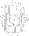
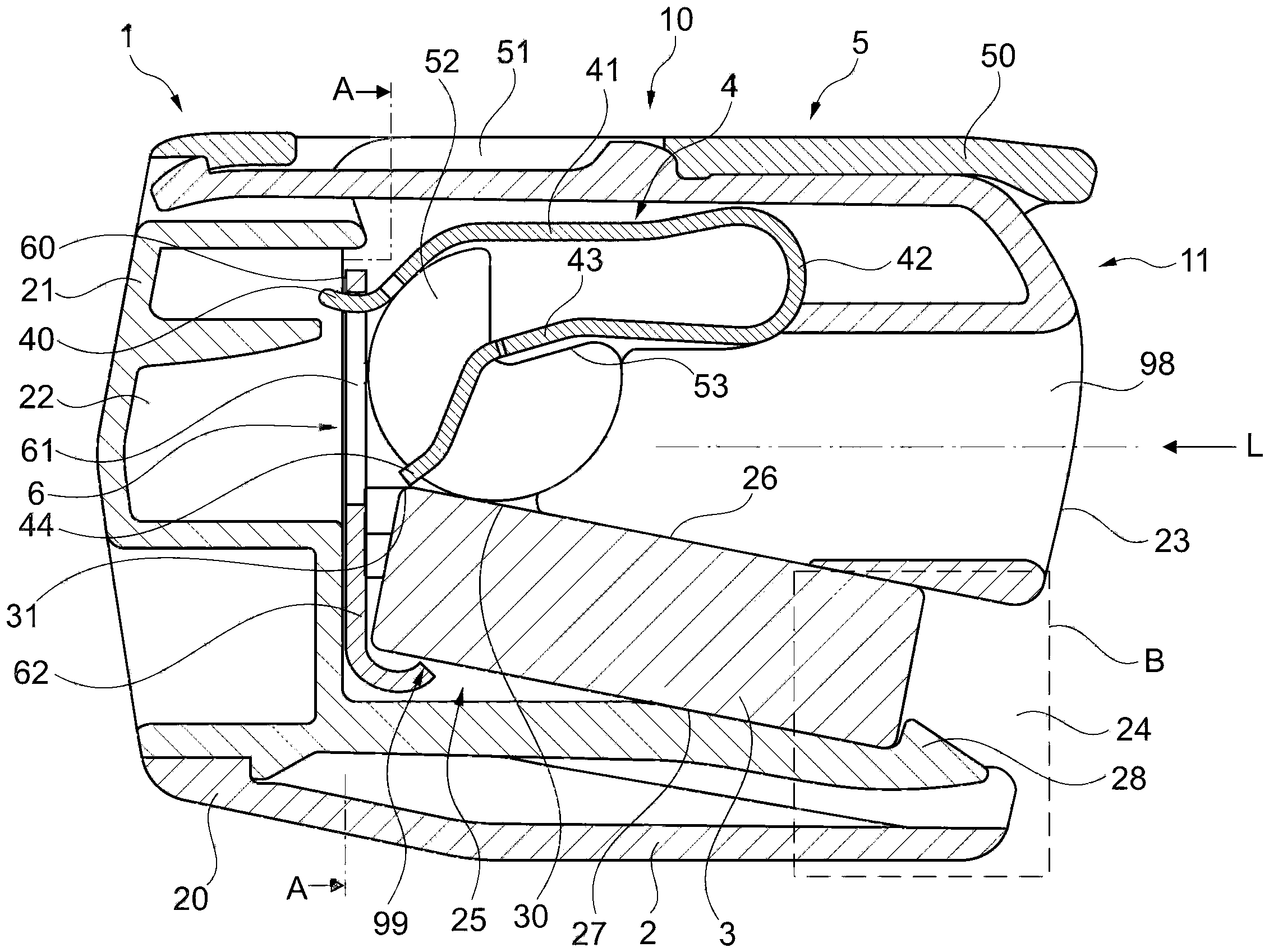
1 - eine Leiteranschlussklemme in seitlicher Schnittdarstellung und -
2 - dieLeiteranschlussklemme gemäß 1 in einer Ansicht auf eine Leitereinführseite und -
3 - eine Schnittansicht der Leiteranschlussklemme gemäß in1 eingezeichneten Schnittlinie A-A und -
4 - eine alternative Ausführungsform der Leiteranschlussklemme in dem in1 markierten Bereich B und -
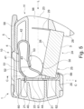
5 - eine weitere Ausführungsform einer Leiteranschlussklemme in seitlicher Schnittdarstellung und -
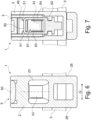
6 - dieLeiteranschlussklemme gemäß 5 in einer Ansicht auf eine Leitereinführseite und -
7 - eine Schnittansicht der Leiteranschlussklemme gemäß der in5 eingezeichneten Schnittlinie C-C.
-
1 - a conductor connection terminal in a side sectional view and -
2 - the conductor connection terminal according to1 in a view of a conductor insertion page and -
3 - a sectional view of the conductor connection terminal according to in1 marked section line AA and -
4 - an alternative embodiment of the conductor connection terminal in the in1 marked area B and -
5 - Another embodiment of a conductor connection terminal in a side sectional view and -
6 - the conductor connection terminal according to5 in a view of a conductor insertion page and -
7 - a sectional view of the conductor connection terminal according to in5 marked cutting line CC.
In den Figuren werden folgende Bezugszeichen verwendet:
- 1
- Leiteranschlussklemme
- 2
- Gehäuse
- 3
- Sammelschiene
- 4
- Klemmfeder
- 5
- Betätigungshebel
- 6
- Halterahmen
- 10
- Betätigungsseite
- 11
- Leitereinführseite
- 20
- erstes Gehäusebauteil
- 21
- zweites Gehäusebauteil
- 22
- Leiteraufnahmekammer
- 23
- Leitereinführungsöffnung
- 24
- Einsetzöffnung
- 25
- Aufnahmeraum
- 26
- Positionierelement
- 27
- Positionierelement
- 28
- Positionierelement
- 29
- Einschnitt
- 30
- Oberfläche der Sammelschiene
- 31
- Eckkante der Sammelschiene
- 40
- freies Ende des Anlageschenkels
- 41
- Anlageschenkel
- 42
- Federbogen
- 43
- Klemmschenkel
- 44
- freies Ende des Klemmschenkels
- 50
- manuelles Betätigungselement
- 51
- Seitenwange
- 52
- Lagerungsscheibe
- 53
- Betätigungskante
- 60
- Steg, erstes Lager
- 61
- Aussparung
- 62
- Zugelement
- 63
- Steg
- 64
- Steg
- 98
- Leitereinführungskanal
- 99
- zweites Lager
- L
- Leitereinführungsrichtung
- Q
- Querrichtung
- 1
- Conductor connection terminal
- 2
- Housing
- 3
- bus bar
- 4
- Clamping spring
- 5
- Operating lever
- 6
- Holding frame
- 10
- Actuation side
- 11
- Ladder entry side
- 20
- first housing component
- 21
- second housing component
- 22
- Conductor receiving chamber
- 23
- Conductor entry opening
- 24
- Insertion opening
- 25
- Recording room
- 26
- Positioning element
- 27
- Positioning element
- 28
- Positioning element
- 29
- incision
- 30
- Busbar surface
- 31
- Corner edge of the busbar
- 40
- free end of the contact leg
- 41
- investment leg
- 42
- Feather bow
- 43
- clamping leg
- 44
- free end of the clamping leg
- 50
- manual actuator
- 51
- side cheek
- 52
- bearing disk
- 53
- Operating edge
- 60
- Jetty, first camp
- 61
- recess
- 62
- Tension element
- 63
- web
- 64
- web
- 98
- Conductor entry channel
- 99
- second camp
- L
- Conductor insertion direction
- Q
- Transverse direction
Die in
Das Gehäuse 2 weist eine Leiteraufnahmekammer 22, eine Leitereinführungsöffnung 23, eine Einsetzöffnung 24, einen Aufnahmeraum 25 zur Aufnahme eines Abschnitts der Sammelschiene 3 sowie Positionierelemente 26, 27, 28 auf, die zur Positionierung der Sammelschiene 3 relativ zum Aufnahmeraum 25 in einer definierten Einbaulage dienen. Die Leiteraufnahmekammer 22 kann zum Beispiel durch einen Teil des zweiten Gehäusebauteils 21 gebildet sein, die übrigen erwähnten Elemente des Gehäuses 2 können am ersten Gehäusebauteil 20 ausgebildet sein. Die Leitereinführungsöffnung 23 befindet sich an einer Leitereinführseite 11 der Leiteranschlussklemme 1. An die Leitereinführungsöffnung 23 schließt sich im Inneren des Gehäuses 2 ein Leitereinführungskanal 98 an, der beispielsweise zumindest teilweise durch Wände des Gehäuses 2 umgeben sein kann.The
Ein elektrischer Leiter, der an der Leiteranschlussklemme 1 angeschlossen werden soll, kann in einer Leitereinführrichtung L durch die Leitereinführöffnung 23 zu einer nachfolgend noch erläuterten Klemmstelle geführt werden. Die Einsetzöffnung 24 dient zum Einsetzen eines Abschnitts der Sammelschiene 3 in den Aufnahmeraum 25. Ist dieser Abschnitt der Sammelschiene 3 vollständig eingesetzt, ergibt sich der in
Die Positionierelemente 26, 27 können beispielsweise als einander gegenüberliegende Gleitkanten des Gehäuses 2 ausgebildet sein, an denen die Sammelschiene während ihres Einsetzens durch die Einsetzöffnung 24 in den Aufnahmeraum 25 geführt ist und letztendlich in der Einbaulage gehalten ist. Das Positionierelement 28 kann als Rastelement ausgebildet sein, das an einer federnden Rastzunge des Gehäuses 2 angeordnet ist. Diese Rastzunge gibt beim Einsetzen der Sammelschiene 3 etwas nach und schnappt dann bei Erreichen der Einbaulage der Sammelschiene 3 in dem Aufnahmeraum 25 wieder zurück, wodurch die Sammelschiene 3 durch Verrastung in dem Aufnahmeraum 25 fixiert ist. Auf der dem Positionierelement 28 abgewandten Seite kann die Position der Sammelschiene 3 beispielsweise durch den Halterahmen 6 fixiert sein.The
Die Klemmfeder 4 weist einen Anlageschenkel 41, einen sich an den Anlageschenkel 41 anschließenden Federbogen 42 und einen sich an den Federbogen 42 anschließenden Klemmschenkel 43 auf. Der Anlageschenkel ist über sein freies Ende 40 an dem Halterahmen 6 fixiert und dort abgestützt, beispielsweise indem das freie Ende 40 dort hinter einem Steg 60 des Halterahmens 6 eingehängt ist. Der Steg 60 kann auf diese Weise ein erstes Lager 60 zur Aufnahme des Anlageschenkels 41 bilden. Der Klemmschenkel 43 endet an einem freien Ende 44, an dem eine Klemmkante vorhanden sein kann. Mittels des freien Endes 44 beziehungsweise der Klemmkante kann ein elektrischer Leiter an einer Oberfläche 30 der Sammelschiene 3 angeklemmt werden. Die Klemmstelle des aus diese Weise realisierten Federkraftklemmanschlusses wird somit zwischen dem freien Ende 44 beziehungsweise der Klemmkante des Klemmschenkels 43 und der Oberfläche 30 der Sammelschiene 3 gebildet. Die Klemmstelle kann insbesondere unter Zuhilfenahme der Eckkante 31 der Sammelschiene 3 gebildet sein.The clamping
Der Halterahmen 6 weist eine Aussparung 61 auf. Ein anzuklemmender elektrischer Leiter, der durch die Leitereinführungsöffnung 23 eingeführt wird, wird zunächst durch den sich an die Leitereinführungsöffnung 23 anschließenden Leitereinführungskanal 98 geführt. Im Bereich des Betätigungshebels 5 erfolgt die Führung des elektrischen Leiters durch jeweils seitlich angeordnete Lagerungsscheiben 52. An der Leiterführung sind außerdem der der Klemmschenkel 43 und die Oberfläche 30 der Sammelschiene 3 beteiligt. Der elektrische Leiter kann durch die Aussparung 61 hindurch bis in den Leiteraufnahmeraum 22 eingeführt werden, durch den auch ein Endanschlag zur Begrenzung der Tiefe des Einsteckens des elektrischen Leiters gebildet ist.The holding
Der Halterahmen 6 wird unterhalb der Aussparung 61 durch ein Zugelement 62 fortgesetzt, hinter dem die Sammelschiene 3 eingehängt ist. Das Zugelement 62 kann zum Beispiel mit einem abgebogenen freien Ende enden, das ein zweites Lager 99 bildet, auf dem die Sammelschiene 3 aufliegt. Die Klemmfeder 4 überträgt durch den Klemmschenkel 43 eine Klemmkraft direkt oder indirekt auf die Sammelschiene 3. Gegenüber dieser Klemmkraft wird die Sammelschiene 3 durch das Zugelement 62 abgestützt, das wiederum über den Halterahmen 6 mit dem Anlageschenkel 41 verbunden ist. Auf diese Weise wird ein selbsttragender Kontakteinsatz der Leiteranschlussklemme 1 realisiert.The holding
Der Betätigungshebel 5 ist zwecks manueller Betätigung an einer Betätigungsseite 10 der Leiteranschlussklemme 1 zugänglich. Der Betätigungshebel 5 weist ein manuelles Betätigungselement 50 auf, an dem der Betätigungshebel 5 manuell zu betätigen ist. Der Betätigungshebel 5 geht vom manuellen Betätigungselement 50 über in einen Bereich, in dem der Betätigungshebel 50 sich aufgabelt in jeweils eine links und eine rechts angeordnete Seitenwange 51. Die Seitenwangen 51 können sich seitlich beispielsweise noch über den Halterahmen 6 hinaus erstrecken. An denen einander zugewandten Innenseiten der Seitenwangen 51 sind jeweilige Federbetätigungskörper angebracht, an denen jeweils eine erste und eine zweite Lagerungsscheibe 52 angeordnet ist. Über die Lagerungsscheiben 52 ist der Betätigungshebel 5 verschwenkbar, das heißt drehbar, in der Leiteranschlussklemme 1 gelagert und kann dabei insbesondere auf der Oberfläche 30 der Sammelschiene 3 aufgelagert sein. In diesem Fall gleitet der Betätigungshebel 5 mit den Lagerungsscheiben 52 bei einer Verschwenkbewegung auf der Sammelschiene 3 ab.The operating
Die Federbetätigungskörper weisen jeweils einen V-förmigen Einschnitt auf, durch den eine jeweilige Betätigungskante 53 gebildet ist. Die Betätigungskante 53 wirkt auf den Klemmschenkel 43 ein. Wird der Betätigungshebel 5 von der in
Die
Die
Die
Während bei den bisher erläuterten Ausführungsformen der Leiteranschlussklemme 1 die Einsetzöffnung 24 an der gleichen Gehäuseseite des Gehäuses 2 wie die Leitereinführungsöffnung 23 angeordnet ist, nämlich an der Leitereinführseite 11, wird anhand der in den
Erkennbar ist, dass in diesem Fall nur die Positionierelemente 26, 28 vorhanden sind. Die Sammelschiene 3 wird derart in den Aufnahmeraum 25 eingeführt, dass sie zunächst zwischen dem freien Ende 44 des Klemmschenkels 43 und dem Zugelement 62 eingeschoben wird und dann mittels einer Verkippbewegung hinter dem Positionierelement 28 eingerastet wird. Um eine ausreichende Beweglichkeit der mit dem Positionierelement 28 verbundenen Rastzunge zu gewährleisten, kann das Gehäuse 2, insbesondere das erste Gehäuseteil 20, eine längliche Einkerbung oder einen Einschnitt 29 aufweisen.It can be seen that in this case only the
Wie insbesondere durch die in
Im Übrigen ist die Leiteranschlussklemme gemäß den
Claims (18)
Priority Applications (5)
| Application Number | Priority Date | Filing Date | Title |
|---|---|---|---|
| DE102019131653.7A DE102019131653B4 (en) | 2019-11-22 | 2019-11-22 | Conductor connection terminal |
| CN202011295200.6A CN112838387B (en) | 2019-11-22 | 2020-11-18 | Terminal clip |
| EP20208383.8A EP3826113B1 (en) | 2019-11-22 | 2020-11-18 | Conductor connecting terminal |
| PL20208383.8T PL3826113T3 (en) | 2019-11-22 | 2020-11-18 | Wire connection terminal |
| US17/101,880 US11355870B2 (en) | 2019-11-22 | 2020-11-23 | Conductor terminal |
Applications Claiming Priority (1)
| Application Number | Priority Date | Filing Date | Title |
|---|---|---|---|
| DE102019131653.7A DE102019131653B4 (en) | 2019-11-22 | 2019-11-22 | Conductor connection terminal |
Publications (2)
| Publication Number | Publication Date |
|---|---|
| DE102019131653A1 DE102019131653A1 (en) | 2021-05-27 |
| DE102019131653B4 true DE102019131653B4 (en) | 2024-01-18 |
Family
ID=73475998
Family Applications (1)
| Application Number | Title | Priority Date | Filing Date |
|---|---|---|---|
| DE102019131653.7A Active DE102019131653B4 (en) | 2019-11-22 | 2019-11-22 | Conductor connection terminal |
Country Status (5)
| Country | Link |
|---|---|
| US (1) | US11355870B2 (en) |
| EP (1) | EP3826113B1 (en) |
| CN (1) | CN112838387B (en) |
| DE (1) | DE102019131653B4 (en) |
| PL (1) | PL3826113T3 (en) |
Citations (7)
| Publication number | Priority date | Publication date | Assignee | Title |
|---|---|---|---|---|
| DE3424482A1 (en) | 1984-06-29 | 1986-01-09 | WAGO Verwaltungsgesellschaft mbH, 4950 Minden | Busbar for electrical power distributors and an electrical power distributor |
| DE20120811U1 (en) | 2001-12-21 | 2003-04-30 | Weidmüller Interface GmbH & Co., 32760 Detmold | Busbar terminal |
| JP2004165045A (en) | 2002-11-14 | 2004-06-10 | Nitto Electric Works Ltd | Terminal block |
| DE10253858A1 (en) | 2002-11-19 | 2004-06-17 | Gerd Conrad | Terminal connector especially modular terminal block, has reception recess provided in parallel support arms of U-shaped clamping body |
| DE102005043877A1 (en) | 2005-09-14 | 2007-03-22 | Wöhner GmbH & Co. KG Elektrotechnische Systeme | Connecting clamp for placing on current-collecting rails comprises a spring clip formed on a base and extending into the inside of the clamp housing between side parts |
| DE102013105263B3 (en) | 2013-05-23 | 2014-09-11 | Wago Verwaltungsgesellschaft Mbh | Connectors |
| DE102013107292A1 (en) | 2013-07-10 | 2015-01-15 | Wago Verwaltungsgesellschaft Mbh | Connectors |
Family Cites Families (8)
| Publication number | Priority date | Publication date | Assignee | Title |
|---|---|---|---|---|
| DE102013101410A1 (en) * | 2013-02-13 | 2014-08-14 | Wago Verwaltungsgesellschaft Mbh | Spring terminal connection and conductor terminal |
| DE102013101406B4 (en) * | 2013-02-13 | 2018-07-12 | Wago Verwaltungsgesellschaft Mbh | Conductor terminal |
| DE202013100635U1 (en) * | 2013-02-13 | 2013-03-04 | Wago Verwaltungsgesellschaft Mbh | Spring terminal and connection terminal for electrical conductors |
| DE102014102517B4 (en) * | 2014-02-26 | 2021-06-10 | Wago Verwaltungsgesellschaft Mbh | Connecting terminal and spring-loaded terminal contact for this |
| EP3038213B1 (en) * | 2014-12-22 | 2017-01-11 | Wago Verwaltungsgesellschaft mbH | Cable connection terminal for clamping at least one electrical conductor |
| DE102015119247B4 (en) * | 2015-11-09 | 2026-03-19 | Wago Verwaltungsgesellschaft Mbh | Connection terminal |
| DE102016122238A1 (en) * | 2016-11-18 | 2018-05-24 | Wago Verwaltungsgesellschaft Mbh | Spring terminal contact for contacting electrical conductors, conductor terminal and method for producing a spring terminal contact |
| CN108075254B (en) * | 2017-07-12 | 2024-03-19 | 盐城世明电子器件有限公司 | electrical connector |
-
2019
- 2019-11-22 DE DE102019131653.7A patent/DE102019131653B4/en active Active
-
2020
- 2020-11-18 EP EP20208383.8A patent/EP3826113B1/en active Active
- 2020-11-18 CN CN202011295200.6A patent/CN112838387B/en active Active
- 2020-11-18 PL PL20208383.8T patent/PL3826113T3/en unknown
- 2020-11-23 US US17/101,880 patent/US11355870B2/en active Active
Patent Citations (7)
| Publication number | Priority date | Publication date | Assignee | Title |
|---|---|---|---|---|
| DE3424482A1 (en) | 1984-06-29 | 1986-01-09 | WAGO Verwaltungsgesellschaft mbH, 4950 Minden | Busbar for electrical power distributors and an electrical power distributor |
| DE20120811U1 (en) | 2001-12-21 | 2003-04-30 | Weidmüller Interface GmbH & Co., 32760 Detmold | Busbar terminal |
| JP2004165045A (en) | 2002-11-14 | 2004-06-10 | Nitto Electric Works Ltd | Terminal block |
| DE10253858A1 (en) | 2002-11-19 | 2004-06-17 | Gerd Conrad | Terminal connector especially modular terminal block, has reception recess provided in parallel support arms of U-shaped clamping body |
| DE102005043877A1 (en) | 2005-09-14 | 2007-03-22 | Wöhner GmbH & Co. KG Elektrotechnische Systeme | Connecting clamp for placing on current-collecting rails comprises a spring clip formed on a base and extending into the inside of the clamp housing between side parts |
| DE102013105263B3 (en) | 2013-05-23 | 2014-09-11 | Wago Verwaltungsgesellschaft Mbh | Connectors |
| DE102013107292A1 (en) | 2013-07-10 | 2015-01-15 | Wago Verwaltungsgesellschaft Mbh | Connectors |
Also Published As
| Publication number | Publication date |
|---|---|
| DE102019131653A1 (en) | 2021-05-27 |
| US20210159618A1 (en) | 2021-05-27 |
| EP3826113A1 (en) | 2021-05-26 |
| PL3826113T3 (en) | 2024-09-02 |
| EP3826113B1 (en) | 2024-04-10 |
| US11355870B2 (en) | 2022-06-07 |
| CN112838387B (en) | 2025-08-05 |
| CN112838387A (en) | 2021-05-25 |
Similar Documents
| Publication | Publication Date | Title |
|---|---|---|
| EP2110894B1 (en) | Electrical connector and locking lever for locking two electrical housing sections together | |
| DE102016116966B4 (en) | spring-loaded terminal connection and conductor connection terminal | |
| EP3787121A1 (en) | Conductor connecting terminal | |
| DE102016115601A1 (en) | Spring terminal connection | |
| DE102016122238A1 (en) | Spring terminal contact for contacting electrical conductors, conductor terminal and method for producing a spring terminal contact | |
| DE102012110759A1 (en) | Spring terminal connection and electrical device hereby | |
| DE102018122806A1 (en) | Conductor terminal and contact insert | |
| EP3345259A1 (en) | Holding frame for plug-in connector modules with a locking element under prestress | |
| EP3345257A1 (en) | Holding frame for plug connector modules | |
| DE102019108291A1 (en) | Conductor connection terminal | |
| DE102016112831B4 (en) | Connection terminal | |
| DE2619035C2 (en) | Screwless connection and / or connecting clamp | |
| DE3207495A1 (en) | TERMINAL BOARD ELEMENT FOR CONNECTING SEVERAL ELECTRIC LEADS BY means of SPRING LAMPS | |
| EP1523065B1 (en) | Electrical terminal | |
| DE102019131653B4 (en) | Conductor connection terminal | |
| DE102020114330B4 (en) | Junction box for connecting terminals | |
| DE202004000419U1 (en) | Screwless conductor connection terminal | |
| EP2242146B1 (en) | Load connecting block or separator with clamp structure | |
| DE3523446A1 (en) | Terminal for the detachable connection of at least one connector | |
| WO2023104796A1 (en) | Conductor terminal | |
| DE102012013034A1 (en) | channel system | |
| WO2017182258A1 (en) | Electrical terminal and method | |
| DE2730680C2 (en) | Screwless clamp for electrical conductors | |
| DE202014101570U1 (en) | Clamping spring and contact unit | |
| DE102021110661B4 (en) | Electrical conductor connection element with contact spring |
Legal Events
| Date | Code | Title | Description |
|---|---|---|---|
| R012 | Request for examination validly filed | ||
| R016 | Response to examination communication | ||
| R082 | Change of representative |
Representative=s name: MEISSNER BOLTE PATENTANWAELTE RECHTSANWAELTE P, DE |
|
| R018 | Grant decision by examination section/examining division | ||
| R020 | Patent grant now final |