DE102019124660B3 - Finishing processing system and method of operating a finishing processing system - Google Patents
Finishing processing system and method of operating a finishing processing system Download PDFInfo
- Publication number
- DE102019124660B3 DE102019124660B3 DE102019124660.1A DE102019124660A DE102019124660B3 DE 102019124660 B3 DE102019124660 B3 DE 102019124660B3 DE 102019124660 A DE102019124660 A DE 102019124660A DE 102019124660 B3 DE102019124660 B3 DE 102019124660B3
- Authority
- DE
- Germany
- Prior art keywords
- finishing
- workpiece
- coupling part
- tool
- work station
- Prior art date
- Legal status (The legal status is an assumption and is not a legal conclusion. Google has not performed a legal analysis and makes no representation as to the accuracy of the status listed.)
- Active
Links
- 238000000034 method Methods 0.000 title claims abstract description 11
- 239000012636 effector Substances 0.000 claims abstract description 13
- 230000008878 coupling Effects 0.000 claims description 74
- 238000010168 coupling process Methods 0.000 claims description 74
- 238000005859 coupling reaction Methods 0.000 claims description 74
- 238000001514 detection method Methods 0.000 claims description 3
- 238000003860 storage Methods 0.000 claims description 3
- 238000003754 machining Methods 0.000 description 15
- 239000004575 stone Substances 0.000 description 14
- 230000002093 peripheral effect Effects 0.000 description 8
- 230000010355 oscillation Effects 0.000 description 6
- 238000011031 large-scale manufacturing process Methods 0.000 description 3
- 238000004519 manufacturing process Methods 0.000 description 3
- 238000007730 finishing process Methods 0.000 description 2
- 238000003825 pressing Methods 0.000 description 2
- 238000011144 upstream manufacturing Methods 0.000 description 2
- 238000010521 absorption reaction Methods 0.000 description 1
- 230000003213 activating effect Effects 0.000 description 1
- 230000005540 biological transmission Effects 0.000 description 1
- 230000000694 effects Effects 0.000 description 1
- 238000012432 intermediate storage Methods 0.000 description 1
- 238000012423 maintenance Methods 0.000 description 1
- 239000000463 material Substances 0.000 description 1
- 238000005259 measurement Methods 0.000 description 1
- 238000003908 quality control method Methods 0.000 description 1
- 238000000926 separation method Methods 0.000 description 1
- 238000005406 washing Methods 0.000 description 1
Images


Classifications
-
- B—PERFORMING OPERATIONS; TRANSPORTING
- B25—HAND TOOLS; PORTABLE POWER-DRIVEN TOOLS; MANIPULATORS
- B25J—MANIPULATORS; CHAMBERS PROVIDED WITH MANIPULATION DEVICES
- B25J11/00—Manipulators not otherwise provided for
- B25J11/005—Manipulators for mechanical processing tasks
- B25J11/006—Deburring or trimming
-
- B—PERFORMING OPERATIONS; TRANSPORTING
- B24—GRINDING; POLISHING
- B24B—MACHINES, DEVICES, OR PROCESSES FOR GRINDING OR POLISHING; DRESSING OR CONDITIONING OF ABRADING SURFACES; FEEDING OF GRINDING, POLISHING, OR LAPPING AGENTS
- B24B35/00—Machines or devices designed for superfinishing surfaces on work, i.e. by means of abrading blocks reciprocating with high frequency
-
- B—PERFORMING OPERATIONS; TRANSPORTING
- B25—HAND TOOLS; PORTABLE POWER-DRIVEN TOOLS; MANIPULATORS
- B25J—MANIPULATORS; CHAMBERS PROVIDED WITH MANIPULATION DEVICES
- B25J11/00—Manipulators not otherwise provided for
- B25J11/005—Manipulators for mechanical processing tasks
- B25J11/0065—Polishing or grinding
-
- B—PERFORMING OPERATIONS; TRANSPORTING
- B25—HAND TOOLS; PORTABLE POWER-DRIVEN TOOLS; MANIPULATORS
- B25J—MANIPULATORS; CHAMBERS PROVIDED WITH MANIPULATION DEVICES
- B25J15/00—Gripping heads and other end effectors
- B25J15/0004—Gripping heads and other end effectors with provision for adjusting the gripped object in the hand
Landscapes
- Engineering & Computer Science (AREA)
- Mechanical Engineering (AREA)
- Robotics (AREA)
- Manipulator (AREA)
Abstract
Die Erfindung betrifft ein Finishbearbeitungssystem (10), mit mindestens einer Arbeitsstation (12, 16) zur Bearbeitung eines Werkstücks (14), wobei zumindest eine Arbeitsstation als Finishstation ausgebildet ist, in welcher ein Werkstück mittels eines Finishwerkzeugs finishend bearbeitbar ist, mit einem Robotiksystem (20), das ein mehrachsiges Antriebssystem (36) aufweist zur programmierbaren Vorgabe einer Position eines mit mindestens einer Arbeitsstation interagierenden Effektors und/oder des in mindestens einer Arbeitsstation zu bearbeitenden Werkstücks. Die Erfindung betrifft ferner Verfahren zum Betrieb eines Finishbearbeitungssystems.The invention relates to a finishing processing system (10) with at least one work station (12, 16) for processing a workpiece (14), at least one work station being designed as a finishing station in which a workpiece can be finish-processed by means of a finishing tool, with a robotic system ( 20), which has a multi-axis drive system (36) for the programmable specification of a position of an effector interacting with at least one workstation and / or of the workpiece to be processed in at least one workstation. The invention also relates to methods of operating a finishing system.
Description
Die Erfindung betrifft ein Finishbearbeitungssystem gemäß dem Oberbegriff des Patentanspruchs 1 mit mindestens einer Arbeitsstation zur Bearbeitung eines Werkstücks, wobei zumindest eine Arbeitsstation als Finishstation ausgebildet ist, in welcher ein Werkstück mittels eines Finishwerkzeugs finishend bearbeitbar ist. Des Weiteren betrifft die Erfindung ein Verfahren zum Betrieb eines Finishbearbeitungssystems gemäß dem Oberbegriff des Patentanspruchs 12 sowie ein Verfahren zum Betrieb eines Finishbearbeitungssystems gemäß dem Oberbegriff des Patentanspruchs 14.The invention relates to a finishing system according to the preamble of claim 1 with at least one work station for processing a workpiece, at least one work station being designed as a finishing station in which a workpiece can be finish-processed by means of a finishing tool. The invention also relates to a method for operating a finish machining system according to the preamble of
Finishbearbeitungssysteme der vorstehend genannten Art sind beispielsweise aus der
Aus der
Der vorliegenden Erfindung liegt die Aufgabe zugrunde, ein Finishbearbeitungssystem zu schaffen, mit welchem eine Finishbearbeitung eines Werkstücks auch in einer Klein- oder Kleinstserienherstellung wirtschaftlich darstellbar ist.The present invention is based on the object of creating a finish machining system with which finish machining of a workpiece can also be carried out economically in small or very small series production.
Diese Aufgabe wird bei einem Finishbearbeitungssystem mit den Merkmalen des Oberbegriffs des Patentanspruchs 1 gelöst durch die kennzeichnenden Merkmale des Patentanspruchs 1. Die Aufgabe wird auch gelöst durch ein Verfahren gemäß den Merkmalen des Patentanspruchs 12. Des Weiteren wird die Aufgabe auch gelöst durch ein Verfahren gemäß den Merkmalen des Patentanspruchs 14.This object is achieved in a finishing system with the features of the preamble of claim 1 by the characterizing features of claim 1. The object is also achieved by a method according to the features of
Das mehrachsige Antriebssystem des Robotiksystems ermöglicht es, einen Wirkbereich des mehrachsige Antriebssystems frei positionieren zu können. Somit kann die Position und vorzugsweise auch die Lage eines Effektors und/oder eines Werkstücks vorgegeben werden. Das mehrachsige Antriebssystem weist vorzugsweise mindestens so viele voneinander unabhängige Antriebsachsen auf, dass innerhalb einer Ebene zumindest innerhalb der Reichweite des Robotiksystems sämtliche Positionen erreichbar sind. Vorzugsweise sind so viele Antriebsachsen vorgesehen, dass innerhalb eines dreidimensionalen Raums zumindest innerhalb der Reichweite des Robotiksystems sämtliche Positionen erreichbar sind. Bei den Antriebsachsen kann es sich beispielsweise um Drehachse und/oder Linearachsen handeln. Ein bevorzugtes Beispiel für ein Robotiksystem ist ein 6-Achs-Gelenkroboter.The multi-axis drive system of the robotic system enables an effective area of the multi-axis drive system to be freely positioned. The position and preferably also the location of an effector and / or a workpiece can thus be specified. The multi-axis drive system preferably has at least as many independent drive axes that all positions can be reached within a plane at least within the range of the robotic system. Preferably, so many drive axes are provided that all positions can be reached within a three-dimensional space at least within the range of the robotic system. The drive axes can, for example, be rotary axes and / or linear axes. A preferred example of a robotic system is a 6-axis articulated robot.
Es ist möglich, dass das Robotiksystem stationär ist und ein unbewegbares Gestell aufweist, das beispielsweise an einer Aufstellfläche verankert ist, wodurch eine feste Referenzposition des Robotiksystems vorgebbar ist. Es ist auch möglich, dass das Robotiksystem relativ zu einer Aufstellfläche verfahrbar ist, beispielsweise entlang vorgebbarer Raumachsen oder aber innerhalb eines dem Robotiksystem zugewiesenen Flächenbereichs.It is possible for the robotic system to be stationary and to have an immovable frame which is anchored, for example, on a mounting surface, whereby a fixed reference position of the robotic system can be specified. It is also possible that the robotic system can be moved relative to a set-up area, for example along predeterminable spatial axes or within a surface area assigned to the robotic system.
Das mehrachsige Antriebssystem ist programmierbar, sodass es für unterschiedliche Aufgaben verwendbar ist, insbesondere auch für Aufgaben im Zusammenhang mit der Bearbeitung von Werkstücken in Klein- oder Kleinstserien.The multi-axis drive system is programmable so that it can be used for different tasks, in particular also for tasks in connection with the machining of workpieces in small or very small series.
Vorzugsweise sind mindestens zwei räumlich voneinander getrennte Arbeitsstationen vorgesehen. Eine räumliche Trennung der Arbeitsstationen ermöglicht es im Zusammenspiel mit dem Robotiksystem, dass das Robotiksystem mit einer der Arbeitsstationen über eine bestimmte Zeitdauer hinweg zusammenwirken kann. Während dieser Zeitdauer sind die anderen Arbeitsstationen des Finishbearbeitungssystems unbeeinflusst von dem Robotiksystem zugänglich, was es prinzipiell ermöglicht, - gegebenenfalls auch manuell - Arbeiten oder Tätigkeiten an den anderen Arbeitsstationen durchführen zu können. Somit sind die einzelnen Arbeitsstationen flexibel und einfach nutzbar, anders als bei einer Großserienproduktion, bei welcher angestrebt wird, dass sämtliche Arbeitsstationen ständig aktiv sind.At least two spatially separate work stations are preferably provided. Spatial separation of the workstations, in conjunction with the robotic system, enables the robotic system to interact with one of the workstations over a certain period of time. During this period of time, the other work stations of the finishing processing system are accessible without being influenced by the robotic system, which in principle makes it possible to carry out work or activities on the other work stations - possibly also manually. Thus, the individual workstations can be used flexibly and easily, unlike in large-scale production, in which the aim is that all workstations are constantly active.
Im Rahmen eines vorteilhaften Aspekts des Finishbearbeitungssystems ist es möglich, dass das mehrachsige Antriebssystem die Position, vorzugsweise auch die Lage, eines mit mindestens einer Arbeitsstation, vorzugsweise mit mehreren Arbeitsstationen interagierenden Effektors vorgibt. Hierbei kann es sich beispielsweise um einen Manipulator zum Austausch und/oder zur Ein- oder Nachstellung und/oder zur Wartung eines Werkzeugs, eines Finishwerkzeugs, einer Werkzeugaufnahme oder einer Werkstückaufnahme einer Arbeitsstation handeln. Solche Aufgaben eignen sich insbesondere für nichtproduktive Zeiträume einer Arbeitsstation. Zur Unterstützung vorstehend und nachstehend genannter Manipulationsaufgaben ist es bevorzugt, dass das Robotiksystem einen Rüstspeicher zum Vorhalten von in mindestens einer Arbeitsstation verwendbaren Werkzeugen, Werkzeugaufnahmen und/oder Werkstückaufnahmen oder Teilen davon aufweist.In the context of an advantageous aspect of the finishing system, it is possible for the multi-axis drive system to specify the position, preferably also the location, of an effector that interacts with at least one work station, preferably with several work stations. This can be, for example, a manipulator for exchanging and / or for adjusting or readjusting and / or for maintenance of a tool, a finishing tool, a tool holder or a workpiece holder of a work station. Such tasks are particularly suitable for non-productive periods of time at a workstation. To support the manipulation tasks mentioned above and below, it is preferred that the robotic system have a set-up memory for holding items that can be used in at least one workstation Has tools, tool holders and / or workpiece holders or parts thereof.
Beispielsweise können an der Finishstation folgende Manipulationsaufgaben im Zusammenhang mit einer an der Finishstation angeordneten Werkstückaufnahme durchgeführt werden: Werkstückaufnahme rüsten, insbesondere Werkstücktreiber tauschen, Segmenttreiberelemente lösen, verschieben, tauschen und/oder klemmen, Zentrierrollen einstellen, Anschläge einstellen, Spannzange / Spannbacken / Zentrierspitzen / Mitnehmer tauschen.For example, the following manipulation tasks can be carried out at the finish station in connection with a workpiece holder arranged at the finish station: Set up the workpiece holder, in particular exchange the workpiece driver, loosen, move, exchange and / or clamp segment driver elements, set centering rollers, set stops, collet chucks / clamping jaws / centering pins / drivers To deceive.
Beispielsweise können an der Finishstation folgende Manipulationsaufgaben im Zusammenhang mit der Anordnung eines als Finishstein ausgebildeten Finishwerkzeugs an der Finishstation durchgeführt werden: Verschieben / Nachstellen des Finishsteins: Steinklemmung wird gelöst, Stein nachgeschoben und wieder geklemmt; Wechsel des Finishsteins: Steinklemmung wird gelöst, verbrauchter Stein entnommen, neuer Stein eingesetzt und wieder geklemmt; Tausch des Werkzeughalters mit Finishstein: der Werkzeughalter wird gemeinsam mit dem daran gehaltenen, verbrauchten Finishstein entfernt und durch einen Werkzeughalter mit einem daran gehaltenen, neuen Finishstein ersetzt.For example, the following manipulation tasks can be carried out at the finishing station in connection with the arrangement of a finishing tool designed as a finishing stone at the finishing station: Moving / readjusting the finishing stone: stone clamping is released, stone pushed in and then clamped again; Changing the finishing stone: The stone clamping is released, the used stone is removed, a new stone is inserted and then clamped again; Exchange of the tool holder with finishing stone: the tool holder is removed together with the used finishing stone held on it and replaced by a tool holder with a new finishing stone held on it.
Es ist auch möglich, dass der Effektor eine Erfassungseinrichtung zur Erfassung eines Istzustands eines zu bearbeitenden Werkstücks und/oder eines bearbeitenden Werkstücks und/oder eines Werkzeugs oder eines Finishwerkzeugs aufweist oder ist. Somit ist es möglich, dass das Robotiksystem Qualitätskontrollaufgaben übernimmt, beispielsweise die Vermessung einer Werkstückgeometrie oder einer Oberfläche des Werkstücks oder eines Abnutzungszustands eines Werkzeugs.It is also possible that the effector has or is a detection device for detecting an actual state of a workpiece to be machined and / or a workpiece to be machined and / or a tool or a finishing tool. It is thus possible for the robotic system to take over quality control tasks, for example the measurement of a workpiece geometry or a surface of the workpiece or a state of wear of a tool.
Die Verwendung eines Effektors mit oder in Form eines Manipulators oder mit einer oder in Form einer Erfassungseinrichtung ermöglicht es außerdem, den Personaleinsatz bei der Finishbearbeitung von Werkstücken zu reduzieren.The use of an effector with or in the form of a manipulator or with or in the form of a detection device also makes it possible to reduce the use of personnel in the finish machining of workpieces.
Es ist auch möglich, dass der Effektor das Finishwerkzeug oder ein anderes Werkzeug aufweist oder ist. Das Finishwerkzeug ist in der Arbeitsstation einsetzbar, die als Finishstation ausgebildet ist. Das andere Werkzeug ist vorzugsweise in einer von der Finishstation abweichenden Arbeitsstation einsetzbar. It is also possible that the effector has or is the finishing tool or another tool. The finishing tool can be used in the work station, which is designed as a finishing station. The other tool can preferably be used in a work station that differs from the finishing station.
Bei dem Finishwerkzeug kann es sich beispielsweise um einen Finishstein oder um ein Finishband handeln. Bevorzugt ist es, dass das Finishwerkzeug an einer Finisheinheit gehalten ist, sodass das mehrachsige Antriebssystem auch zur programmierbaren Vorgabe einer Position (und vorzugsweise auch der Lage) weiterer Finisheinrichtungen dient, bei denen es sich beispielsweise um einen Vorrat für Finishband, um eine Antrieb für den Vorschub eines Finishbands und/oder einen Antrieb zur Erzeugung einer Oszillationsbewegung des Finishwerkzeugs handeln kann.The finishing tool can be, for example, a finishing stone or a finishing belt. It is preferred that the finishing tool is held on a finishing unit so that the multi-axis drive system is also used for the programmable specification of a position (and preferably also the location) of further finishing devices, which are, for example, a supply for finishing tape, a drive for the Can act feed of a finishing belt and / or a drive for generating an oscillating movement of the finishing tool.
Gemäß einem vorteilhaften Aspekt des Finishbearbeitungssystems ermöglicht das mehrachsige Antriebssystem eine programmierbare Vorgabe einer Position, vorzugsweise auch der Lage, des in den Arbeitsstationen zu bearbeitenden Werkstücks. In vorteilhafter Weise handelt es sich dabei um ein Werkstück einer Klein- oder Kleinstserie. Die mehrachsige Programmierbarkeit der Position (und optional der Lage) des Werkstücks erfordert gegebenenfalls eine geringfügig erhöhte Nebenzeit, innerhalb welcher das Werkstück von einer Arbeitsstation zur nächsten Arbeitsstation überführt wird. Diese Erhöhung der Nebenzeit wird bewusst in Kauf genommen und bezieht sich auf einen Vergleich zu konventionellen, einachsigen Transporteinrichtungen, welche in der Großserienfertigung eingesetzt werden. Diese stellen eine schnelle, jedoch nicht flexible Transportmöglichkeit für eine Vielzahl von Werkstücken bereit, beispielsweise durch Verwendung von Transportbändern oder Drehtischen.According to an advantageous aspect of the finishing processing system, the multi-axis drive system enables a programmable specification of a position, preferably also the location, of the workpiece to be processed in the work stations. Advantageously, this is a workpiece in a small or very small series. The multi-axis programmability of the position (and optionally the location) of the workpiece may require a slightly increased non-productive time within which the workpiece is transferred from one workstation to the next. This increase in non-productive time is consciously accepted and relates to a comparison with conventional, single-axis transport devices that are used in large-scale production. These provide a fast, but not flexible transport option for a large number of workpieces, for example by using conveyor belts or turntables.
Zur Unterstützung etwaiger Werkstücktransportaufgaben ist es möglich, dass das Robotiksystem einen Werkstückspeicher zum Vorhalten von in mindestens einer Arbeitsstation zu bearbeitenden Werkstücken aufweist.To support any workpiece transport tasks, it is possible for the robotic system to have a workpiece storage device for holding workpieces to be processed in at least one work station.
Nachfolgend werden weitere, besonders bevorzugte Ausgestaltungen des Finishbearbeitungssystems erläutert. Beispielsweise ist es bevorzugt, dass zumindest eine Arbeitsstation als Entgratungsstation ausgebildet ist, wobei ein Entgratungswerkzeug an der Arbeitsstation oder in dem Wirkbereich des mehrachsigen Antriebssystems gelagert sein kann.Further, particularly preferred configurations of the finishing system are explained below. For example, it is preferred that at least one work station is designed as a deburring station, it being possible for a deburring tool to be mounted on the work station or in the active area of the multi-axis drive system.
Zur Vereinfachung der Handhabung des zumindest in der Finishstation finishend zu bearbeitenden Werkstücks wird vorgeschlagen, dass das Robotiksystem eine Aufnahmeeinrichtung zur Aufnahme des finishend zu bearbeitenden Werkstücks aufweist. Diese Aufnahmeeinrichtung ist mit dem Wirkbereich des mehrachsigen Antriebssystems verbunden, sodass die Position und vorzugsweise auch die Lage der Aufnahmeeinrichtung und eines in der Aufnahmeeinrichtung aufgenommenen Werkstücks mittels des mehrachsigen Antriebssystems vorgebbar ist.To simplify the handling of the workpiece to be finished at least in the finishing station, it is proposed that the robotic system have a receiving device for receiving the workpiece to be finished. This receiving device is connected to the active area of the multi-axis drive system, so that the position and preferably also the location of the receiving device and a workpiece received in the receiving device can be predetermined by means of the multi-axis drive system.
Bei der Aufnahmeeinrichtung kann es sich beispielsweise um einen Träger handeln, der mit einem Spindelstock und einem Reitstock versehen ist, sodass beispielsweise ein Werkstück in Form einer Kurbelwelle, einer Nockenwelle oder einer Getriebewelle um eine Werkstückachse drehbar aufgenommen werden kann.The receiving device can be, for example, a carrier which is provided with a headstock and a tailstock, so that for example a workpiece in the form of a crankshaft, a camshaft or a Gear shaft can be rotatably received about a workpiece axis.
Zur weiteren Vereinfachung des Handlings des finishend zu bearbeitenden Werkstücks wird vorgeschlagen, dass das Robotiksystem einen Rotationsantrieb aufweist, mittels welchem das finishend zu bearbeitende Werkstück um eine Werkstückachse rotierend antreibbar ist. Dieser Rotationsantrieb kann beispielsweise an einem Spindelstock bereitgestellt werden.To further simplify the handling of the workpiece to be finished, it is proposed that the robotic system have a rotary drive by means of which the workpiece to be finished can be driven to rotate about a workpiece axis. This rotary drive can be provided on a headstock, for example.
Nachfolgend werden Ausführungsformen des Finishbearbeitungssystems erläutert, welche es ermöglichen, die Flexibilität eines mehrachsigen Antriebssystems eines Robotiksystems mit der Genauigkeit stationärer Systeme kombinieren zu können, was für die Durchführung des Finishverfahrens und die Einhaltung kleinstmöglicher Fertigungstoleranzen von hoher Bedeutung ist. Erfindungsgemäß wird vorgeschlagen, dass eine Kopplungseinrichtung vorgesehen ist, welche zwei wiederholbar lösbar miteinander verbindbare Koppelteile aufweist, wobei ein erstes Koppelteil dem Robotiksystem zugeordnet ist und wobei eine Position des ersten Koppelteils mittels des mehrachsigen Antriebssystems vorgebbar ist, und wobei ein zweites Koppelteil einer Arbeitsstation zugeordnet ist. Das zweite Koppelteil ermöglicht die Vorgabe einer der Arbeitsstation zugeordneten Referenzposition, die sich bei einer Kopplung des zweiten Koppelteils mit dem ersten Koppelteil auf das erste Koppelteil und somit auf das mehrachsige Antriebssystem überträgt.Embodiments of the finishing system are explained below, which make it possible to combine the flexibility of a multi-axis drive system of a robotic system with the accuracy of stationary systems, which is of great importance for carrying out the finishing process and maintaining the smallest possible manufacturing tolerances. According to the invention, it is proposed that a coupling device is provided which has two coupling parts which can be repeatedly and detachably connected to one another, a first coupling part being assigned to the robotic system and a position of the first coupling part being predeterminable by means of the multi-axis drive system, and a second coupling part being assigned to a work station . The second coupling part enables the specification of a reference position assigned to the workstation, which is transferred to the first coupling part and thus to the multi-axis drive system when the second coupling part is coupled to the first coupling part.
Insbesondere ist es bevorzugt, wenn das erste Koppelteil und das zweite Koppelteil in ihrem miteinander verbundenen Zustand miteinander formschlüssig verbunden sind. Ein solcher Formschluss wird optional durch zusätzliche Klemmelemente (Nullpunktspannsystem) unterstützt und ermöglicht eine Aufnahme und Ableitung von Kräften, die bei der Bearbeitung eines Werkstücks, insbesondere bei der Finishbearbeitung eines Werkstücks, entstehen. Diese Kräfte können in stationäre Teile einer Arbeitsstation abgeleitet werden und wirken dann nicht auf das mehrachsige Antriebssystem. Dies hat zur Folge, dass das mehrachsige Antriebssystem trotz seiner aufgrund einer offenen kinematischen Kette naturgemäß höheren Instabilität dennoch zur Durchführung hochgenauer Bearbeitungsaufgaben (insbesondere Finishbearbeitungsaufgaben) verwendet werden kann.In particular, it is preferred if the first coupling part and the second coupling part are positively connected to one another in their interconnected state. Such a form fit is optionally supported by additional clamping elements (zero point clamping system) and enables the absorption and dissipation of forces that arise when machining a workpiece, in particular when finishing a workpiece. These forces can be diverted into stationary parts of a work station and then do not act on the multi-axis drive system. As a result, the multi-axis drive system, despite its naturally higher instability due to an open kinematic chain, can nevertheless be used to carry out highly precise machining tasks (in particular finishing machining tasks).
Es wird ferner vorgeschlagen, dass das zweite Koppelteil entlang mindestens einer Bewegungsachse bewegbar ist, wodurch die Referenzposition der betreffenden Arbeitsstation veränderbar ist.It is also proposed that the second coupling part can be moved along at least one movement axis, whereby the reference position of the work station in question can be changed.
Es ist ferner bevorzugt, wenn eine der Arbeitsstation zugeordnete Führungseinrichtung zur Führung des zweiten Koppelteils längs der mindestens einen Bewegungsachse vorgesehen ist. Beispielsweise handelt es sich um eine geradlinige Bewegungsachse, entlang welcher das zweite Koppelteil bewegbar ist.It is also preferred if a guide device assigned to the work station is provided for guiding the second coupling part along the at least one movement axis. For example, it is a straight-line movement axis along which the second coupling part can be moved.
Bei einem bevorzugten Verfahren zum Betrieb eines vorstehend beschriebenen Finishbearbeitungssystems ist vorgesehen, dass in einem miteinander verbundenen Zustand des ersten Koppelteils und des zweiten Koppelteils das mehrachsige Antriebssystem des Robotiksystems aktiv ist. Dies bedeutet, dass die Antriebe des Robotiksystems verwendet werden, um das erste Koppelteil und das mit dem ersten Koppelteil verbundene zweite Koppelteil anzutreiben. Da aber das zweite Koppelteil in einer Führungseinrichtung geführt ist, unterliegt die Bewegung eines mit dem mehrachsigen Antriebssystem verbundenen Effektors oder Werkstücks keiner Abweichung in einer Richtung quer zu der Bewegungsachse. Dies ermöglicht eine hochpräzise Führung eines Effektors oder eines Werkstücks längs der Bewegungsachse unter Verwendung des Robotiksystems und dessen mehrachsigen Antriebssystems.In a preferred method for operating a finish machining system described above, it is provided that the multi-axis drive system of the robotic system is active when the first coupling part and the second coupling part are connected to one another. This means that the drives of the robotic system are used to drive the first coupling part and the second coupling part connected to the first coupling part. However, since the second coupling part is guided in a guide device, the movement of an effector or workpiece connected to the multi-axis drive system is not subject to any deviation in a direction transverse to the movement axis. This enables a highly precise guidance of an effector or a workpiece along the movement axis using the robotic system and its multi-axis drive system.
Für den Fall der Bewegbarkeit des zweiten Koppelteils entlang mindestens einer Bewegungsachse ist es ferner möglich, dass eine der Arbeitsstation zugeordnete Antriebseinrichtung zum Antrieb des zweiten Koppelteils längs der mindestens einen Bewegungsachse vorgesehen ist. Dies ermöglicht eine von dem mehrachsigen Antriebssystem unabhängige Bewegung. Bei einem bevorzugten Verfahren zum Betrieb eines solchen Finishbearbeitungssystems ist vorgesehen, dass in einem miteinander verbundenen Zustand des ersten Koppelteils und des zweiten Koppelteils die der Arbeitsstation zugeordnete Antriebseinrichtung aktiv ist und das mehrachsige Antriebssystem des Robotiksystems inaktiv ist. Das mehrachsige Antriebssystem wird also „weich“ geschaltet, sodass es der Bewegung des zweiten Koppelteils und des damit verbundenen ersten Koppelteils passiv folgt.In the event that the second coupling part can be moved along at least one movement axis, it is also possible that a drive device assigned to the work station is provided for driving the second coupling part along the at least one movement axis. This enables a movement that is independent of the multi-axis drive system. In a preferred method for operating such a finishing system, it is provided that, when the first coupling part and the second coupling part are connected to one another, the drive device assigned to the work station is active and the multi-axis drive system of the robotic system is inactive. The multi-axis drive system is therefore switched “softly” so that it passively follows the movement of the second coupling part and the associated first coupling part.
Weitere Merkmale und Vorteile der Erfindung sind Gegenstand der nachfolgenden Beschreibung und der zeichnerischen Darstellung bevorzugter Ausführungsbeispiele.Further features and advantages of the invention are the subject matter of the following description and the drawing of preferred exemplary embodiments.
In der Zeichnung zeigt
-
1 eine perspektivische Ansicht einer Ausführungsform eines Finishbearbeitungssystems; -
2 eine perspektivische Ansicht einer als Entgratungsstation ausgebildeten Arbeitsstation des Finishbearbeitungssystems gemäß1 ; -
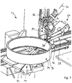
3 eine perspektivische Ansicht einer als Finishstation ausgebildeten Arbeitsstation des Finishbearbeitungssystems gemäß1 ; -
4 eine Seitenansicht der Finishstation gemäß3 , wobei eine Kopplungseinrichtung des Finishbearbeitungssystems in einem entkoppelten Lösezustand dargestellt ist; -
5 eine der4 entsprechende Seitenansicht, wobei die Kopplungseinrichtung in einem gekoppelten Verbindungszustand dargestellt ist; -
6 eine perspektivische Ansicht einer weiteren Ausführungsform einer Arbeitsstation eines Finishbearbeitungssystems in Form einer Finishstation bei Durchführung einer ersten Bearbeitungsaufgabe; -
7 eine perspektivische Ansicht der Arbeitsstation gemäß6 bei Durchführung einer zweiten Bearbeitungsaufgabe; und -
8 eine weitere perspektivische Ansicht der Arbeitsstation gemäß6 , mit einer weiteren Ausführungsform einer Kopplungseinrichtung eines Finishbearbeitungssystems.
-
1 Fig. 3 is a perspective view of one embodiment of a finishing system; -
2 a perspective view of a work station designed as a deburring station of the finishing processing system according to FIG1 ; -
3 a perspective view of a work station designed as a finishing station of the finishing processing system according to FIG1 ; -
4th a side view of the finishing station according to3 , wherein a coupling device of the finishing processing system is shown in a decoupled release state; -
5 one of the4th corresponding side view, wherein the coupling device is shown in a coupled connection state; -
6 a perspective view of a further embodiment of a work station of a finishing processing system in the form of a finishing station when performing a first processing task; -
7th a perspective view of the workstation according to6 when performing a second processing task; and -
8th a further perspective view of the workstation according to FIG6 , with a further embodiment of a coupling device of a finishing processing system.
Ein Finishbearbeitungssystem ist in der Zeichnung insgesamt mit dem Bezugszeichen
Das Finishbearbeitungssystem
Die Entgratungsstation kann der Finishstation bearbeitungstechnisch vor- oder nachgeschaltet sein. Es können auch (nicht dargestellte) Stationen zur Abholung, Zwischenspeicherung oder Endspeicherung von Werkstücken
Das Finishbarbeitungssystem
Die genannten Achsen des Antriebssystems
Bei dem in
Bei dem Werkstück
Zur entgratenden Bearbeitung des Werkstücks
Das Werkstück
Zur finishenden Bearbeitung der Umfangsfläche
Die Finisheinheit
Die Finisheinheit
Die Finisheinheit
Das zweite Koppelteil
Die beiden Koppelteile
Eine finishende Bearbeitung der Umfangsfläche
Durch Aktivierung des Rotationsantriebs
Bei dem in den
Das Robotiksystem
In dem Wirkbereich
Der Wirkbereich
Das erste Koppelteil
Die Führungseinrichtung
Ausgehend von einem in
Es ist auch möglich, das Finishwerkzeug
Claims (14)
Priority Applications (1)
| Application Number | Priority Date | Filing Date | Title |
|---|---|---|---|
| DE102019124660.1A DE102019124660B3 (en) | 2019-09-13 | 2019-09-13 | Finishing processing system and method of operating a finishing processing system |
Applications Claiming Priority (1)
| Application Number | Priority Date | Filing Date | Title |
|---|---|---|---|
| DE102019124660.1A DE102019124660B3 (en) | 2019-09-13 | 2019-09-13 | Finishing processing system and method of operating a finishing processing system |
Publications (1)
| Publication Number | Publication Date |
|---|---|
| DE102019124660B3 true DE102019124660B3 (en) | 2021-01-28 |
Family
ID=74099011
Family Applications (1)
| Application Number | Title | Priority Date | Filing Date |
|---|---|---|---|
| DE102019124660.1A Active DE102019124660B3 (en) | 2019-09-13 | 2019-09-13 | Finishing processing system and method of operating a finishing processing system |
Country Status (1)
| Country | Link |
|---|---|
| DE (1) | DE102019124660B3 (en) |
Cited By (1)
| Publication number | Priority date | Publication date | Assignee | Title |
|---|---|---|---|---|
| DE102024119179A1 (en) * | 2024-07-05 | 2026-01-08 | Supfina Grieshaber Gmbh & Co. Kg | Finishing device for finishing a ring-shaped workpiece and finishing system |
Citations (6)
| Publication number | Priority date | Publication date | Assignee | Title |
|---|---|---|---|---|
| DE102009036290A1 (en) * | 2009-08-06 | 2011-04-21 | Thielenhaus Technologies Gmbh | Straight and round circumferential surfaces finish processing method for frame-like housing part of digital camera, involves measuring pressing force of workpiece during processing, and controlling force according to set points requirement |
| DE102011081918A1 (en) * | 2011-08-31 | 2013-02-28 | Nagel Maschinen- Und Werkzeugfabrik Gmbh | Finishing machine for finishing curved workpiece surfaces on workpieces |
| US20140113525A1 (en) * | 2012-10-22 | 2014-04-24 | Apple Inc. | Methods for finishing surfaces using tool center point shift techniques |
| CN206567957U (en) * | 2017-03-06 | 2017-10-20 | 深圳市昌巨科技有限公司 | A kind of grinding apparatus |
| DE102017108426A1 (en) * | 2017-04-20 | 2018-10-25 | Ferrobotics Compliant Robot Technology Gmbh | Grinding machine for robot-assisted grinding |
| US20190262967A1 (en) * | 2018-02-28 | 2019-08-29 | T&D Robotics S.R.L. | Multiple polishing head |
-
2019
- 2019-09-13 DE DE102019124660.1A patent/DE102019124660B3/en active Active
Patent Citations (6)
| Publication number | Priority date | Publication date | Assignee | Title |
|---|---|---|---|---|
| DE102009036290A1 (en) * | 2009-08-06 | 2011-04-21 | Thielenhaus Technologies Gmbh | Straight and round circumferential surfaces finish processing method for frame-like housing part of digital camera, involves measuring pressing force of workpiece during processing, and controlling force according to set points requirement |
| DE102011081918A1 (en) * | 2011-08-31 | 2013-02-28 | Nagel Maschinen- Und Werkzeugfabrik Gmbh | Finishing machine for finishing curved workpiece surfaces on workpieces |
| US20140113525A1 (en) * | 2012-10-22 | 2014-04-24 | Apple Inc. | Methods for finishing surfaces using tool center point shift techniques |
| CN206567957U (en) * | 2017-03-06 | 2017-10-20 | 深圳市昌巨科技有限公司 | A kind of grinding apparatus |
| DE102017108426A1 (en) * | 2017-04-20 | 2018-10-25 | Ferrobotics Compliant Robot Technology Gmbh | Grinding machine for robot-assisted grinding |
| US20190262967A1 (en) * | 2018-02-28 | 2019-08-29 | T&D Robotics S.R.L. | Multiple polishing head |
Cited By (1)
| Publication number | Priority date | Publication date | Assignee | Title |
|---|---|---|---|---|
| DE102024119179A1 (en) * | 2024-07-05 | 2026-01-08 | Supfina Grieshaber Gmbh & Co. Kg | Finishing device for finishing a ring-shaped workpiece and finishing system |
Similar Documents
| Publication | Publication Date | Title |
|---|---|---|
| EP2750829B2 (en) | Finishing machine for finish machining of curved workpiece surfaces on workpieces | |
| EP1418019B2 (en) | Machine tool with at least two tool turrets comprising each a workholder | |
| EP0995539B1 (en) | Machining device for work pieces | |
| DE102016117915B4 (en) | Spindle module for a workpiece processing device | |
| EP0318966A2 (en) | Machine for processing surfaces with a device for positioning work tools | |
| DE102011118747B4 (en) | Method and machine tool for complete machining of wavy workpieces | |
| EP0967038B1 (en) | Device for machining by material removal of workpieces | |
| DE102016015806B4 (en) | Workpiece processing device | |
| DE102012023973A1 (en) | machine tool | |
| EP0885686A1 (en) | Machining centre | |
| DE102017209606A1 (en) | Machine tool for machining a workpiece | |
| DE10307977C5 (en) | Method and device for processing differential housings | |
| CH699901B1 (en) | Apparatus for machining workpieces. | |
| DE19619720A1 (en) | Multi-spindle lathe | |
| DE4022458C2 (en) | ||
| DE20314702U1 (en) | A dual spindle lathe has linear motor driven independent spindles and tool carriers with a central work area in which the workpiece is offered | |
| DE102019124660B3 (en) | Finishing processing system and method of operating a finishing processing system | |
| DE2804584A1 (en) | Machine tool with multiple working stations - has fixed and retractable machining units at stations connected to common power unit | |
| EP2762253B1 (en) | Machine tool for machining workpieces | |
| EP1736264B1 (en) | Device for inside machining of workpieces, especially of differential gear housings | |
| DE102011111677A1 (en) | Processing device for processing workpiece, has workpiece receiving zone and workpiece delivering zone that are provided on right and left sides of processing zones that are separated from each other | |
| EP1985409A1 (en) | Flexible transfer machine with movable workpiece holders | |
| EP0637277B1 (en) | Device for cutting metal-machining | |
| DE102010060471B4 (en) | Machine for finish machining of long, wave-shaped workpieces | |
| DE19504370A1 (en) | Multi-spindle lathe |
Legal Events
| Date | Code | Title | Description |
|---|---|---|---|
| R163 | Identified publications notified | ||
| R012 | Request for examination validly filed | ||
| R018 | Grant decision by examination section/examining division | ||
| R020 | Patent grant now final |