DE102019123632A1 - Container for providing printing ink in an inking unit of a printing machine - Google Patents
Container for providing printing ink in an inking unit of a printing machine Download PDFInfo
- Publication number
- DE102019123632A1 DE102019123632A1 DE102019123632.0A DE102019123632A DE102019123632A1 DE 102019123632 A1 DE102019123632 A1 DE 102019123632A1 DE 102019123632 A DE102019123632 A DE 102019123632A DE 102019123632 A1 DE102019123632 A1 DE 102019123632A1
- Authority
- DE
- Germany
- Prior art keywords
- printing
- ink
- container
- inking
- roller
- Prior art date
- Legal status (The legal status is an assumption and is not a legal conclusion. Google has not performed a legal analysis and makes no representation as to the accuracy of the status listed.)
- Pending
Links
- 238000007639 printing Methods 0.000 title claims abstract description 353
- 238000009516 primary packaging Methods 0.000 claims abstract description 10
- 239000004033 plastic Substances 0.000 claims description 8
- 229920003023 plastic Polymers 0.000 claims description 8
- 239000007769 metal material Substances 0.000 claims description 3
- 230000037431 insertion Effects 0.000 claims 1
- 238000003780 insertion Methods 0.000 claims 1
- 239000000976 ink Substances 0.000 description 128
- 238000007774 anilox coating Methods 0.000 description 82
- 239000003973 paint Substances 0.000 description 76
- 238000004519 manufacturing process Methods 0.000 description 38
- 238000000034 method Methods 0.000 description 29
- 230000008569 process Effects 0.000 description 29
- 238000004140 cleaning Methods 0.000 description 22
- 230000002572 peristaltic effect Effects 0.000 description 18
- 230000033001 locomotion Effects 0.000 description 17
- 230000032258 transport Effects 0.000 description 12
- 238000012546 transfer Methods 0.000 description 11
- 239000002184 metal Substances 0.000 description 8
- 229910052751 metal Inorganic materials 0.000 description 8
- 230000002093 peripheral effect Effects 0.000 description 7
- 239000005028 tinplate Substances 0.000 description 7
- 229910000831 Steel Inorganic materials 0.000 description 6
- 238000005034 decoration Methods 0.000 description 6
- 239000007788 liquid Substances 0.000 description 6
- 239000010959 steel Substances 0.000 description 6
- 229910052782 aluminium Inorganic materials 0.000 description 5
- XAGFODPZIPBFFR-UHFFFAOYSA-N aluminium Chemical compound [Al] XAGFODPZIPBFFR-UHFFFAOYSA-N 0.000 description 5
- 238000013461 design Methods 0.000 description 5
- 230000008859 change Effects 0.000 description 4
- 238000006243 chemical reaction Methods 0.000 description 4
- 239000003086 colorant Substances 0.000 description 4
- 230000008878 coupling Effects 0.000 description 4
- 238000010168 coupling process Methods 0.000 description 4
- 238000005859 coupling reaction Methods 0.000 description 4
- 238000004806 packaging method and process Methods 0.000 description 4
- 238000012545 processing Methods 0.000 description 4
- 239000000725 suspension Substances 0.000 description 4
- 230000009471 action Effects 0.000 description 3
- 239000000853 adhesive Substances 0.000 description 3
- 230000001070 adhesive effect Effects 0.000 description 3
- 239000000443 aerosol Substances 0.000 description 3
- 235000013361 beverage Nutrition 0.000 description 3
- 239000012530 fluid Substances 0.000 description 3
- 238000009434 installation Methods 0.000 description 3
- 239000000463 material Substances 0.000 description 3
- 238000003825 pressing Methods 0.000 description 3
- 238000003756 stirring Methods 0.000 description 3
- 238000011144 upstream manufacturing Methods 0.000 description 3
- IJGRMHOSHXDMSA-UHFFFAOYSA-N Atomic nitrogen Chemical compound N#N IJGRMHOSHXDMSA-UHFFFAOYSA-N 0.000 description 2
- LCGLNKUTAGEVQW-UHFFFAOYSA-N Dimethyl ether Chemical compound COC LCGLNKUTAGEVQW-UHFFFAOYSA-N 0.000 description 2
- ATUOYWHBWRKTHZ-UHFFFAOYSA-N Propane Chemical compound CCC ATUOYWHBWRKTHZ-UHFFFAOYSA-N 0.000 description 2
- ATJFFYVFTNAWJD-UHFFFAOYSA-N Tin Chemical compound [Sn] ATJFFYVFTNAWJD-UHFFFAOYSA-N 0.000 description 2
- 230000004323 axial length Effects 0.000 description 2
- 230000008901 benefit Effects 0.000 description 2
- 239000000919 ceramic Substances 0.000 description 2
- 229920001971 elastomer Polymers 0.000 description 2
- 238000001125 extrusion Methods 0.000 description 2
- 238000012432 intermediate storage Methods 0.000 description 2
- 238000007644 letterpress printing Methods 0.000 description 2
- 230000007246 mechanism Effects 0.000 description 2
- 238000007645 offset printing Methods 0.000 description 2
- 238000010422 painting Methods 0.000 description 2
- 230000001105 regulatory effect Effects 0.000 description 2
- 238000005096 rolling process Methods 0.000 description 2
- 239000007921 spray Substances 0.000 description 2
- 230000001360 synchronised effect Effects 0.000 description 2
- BUHVIAUBTBOHAG-FOYDDCNASA-N (2r,3r,4s,5r)-2-[6-[[2-(3,5-dimethoxyphenyl)-2-(2-methylphenyl)ethyl]amino]purin-9-yl]-5-(hydroxymethyl)oxolane-3,4-diol Chemical compound COC1=CC(OC)=CC(C(CNC=2C=3N=CN(C=3N=CN=2)[C@H]2[C@@H]([C@H](O)[C@@H](CO)O2)O)C=2C(=CC=CC=2)C)=C1 BUHVIAUBTBOHAG-FOYDDCNASA-N 0.000 description 1
- 244000043261 Hevea brasiliensis Species 0.000 description 1
- 229920000459 Nitrile rubber Polymers 0.000 description 1
- 238000005299 abrasion Methods 0.000 description 1
- 239000001273 butane Substances 0.000 description 1
- 239000011248 coating agent Substances 0.000 description 1
- 238000000576 coating method Methods 0.000 description 1
- 238000000641 cold extrusion Methods 0.000 description 1
- 230000006835 compression Effects 0.000 description 1
- 238000007906 compression Methods 0.000 description 1
- 238000010276 construction Methods 0.000 description 1
- 239000002826 coolant Substances 0.000 description 1
- 238000005260 corrosion Methods 0.000 description 1
- 230000007797 corrosion Effects 0.000 description 1
- 235000013365 dairy product Nutrition 0.000 description 1
- 230000001419 dependent effect Effects 0.000 description 1
- 238000001514 detection method Methods 0.000 description 1
- 230000001627 detrimental effect Effects 0.000 description 1
- 238000011161 development Methods 0.000 description 1
- 230000018109 developmental process Effects 0.000 description 1
- 238000010017 direct printing Methods 0.000 description 1
- 238000009826 distribution Methods 0.000 description 1
- 230000000694 effects Effects 0.000 description 1
- 239000013013 elastic material Substances 0.000 description 1
- 239000000806 elastomer Substances 0.000 description 1
- 230000002996 emotional effect Effects 0.000 description 1
- 230000001747 exhibiting effect Effects 0.000 description 1
- 239000004744 fabric Substances 0.000 description 1
- 238000007667 floating Methods 0.000 description 1
- 239000006260 foam Substances 0.000 description 1
- 235000013305 food Nutrition 0.000 description 1
- 239000007789 gas Substances 0.000 description 1
- 239000011521 glass Substances 0.000 description 1
- 230000005484 gravity Effects 0.000 description 1
- 238000007641 inkjet printing Methods 0.000 description 1
- 238000010409 ironing Methods 0.000 description 1
- 210000001503 joint Anatomy 0.000 description 1
- 238000003754 machining Methods 0.000 description 1
- 238000012423 maintenance Methods 0.000 description 1
- 239000000203 mixture Substances 0.000 description 1
- IJDNQMDRQITEOD-UHFFFAOYSA-N n-butane Chemical compound CCCC IJDNQMDRQITEOD-UHFFFAOYSA-N 0.000 description 1
- OFBQJSOFQDEBGM-UHFFFAOYSA-N n-pentane Natural products CCCCC OFBQJSOFQDEBGM-UHFFFAOYSA-N 0.000 description 1
- 229920003052 natural elastomer Polymers 0.000 description 1
- 229920001194 natural rubber Polymers 0.000 description 1
- 229910052757 nitrogen Inorganic materials 0.000 description 1
- 235000011837 pasties Nutrition 0.000 description 1
- 239000000049 pigment Substances 0.000 description 1
- 229920002635 polyurethane Polymers 0.000 description 1
- 239000004814 polyurethane Substances 0.000 description 1
- 239000011148 porous material Substances 0.000 description 1
- 239000001294 propane Substances 0.000 description 1
- 239000003380 propellant Substances 0.000 description 1
- 230000002787 reinforcement Effects 0.000 description 1
- 230000008439 repair process Effects 0.000 description 1
- 239000005060 rubber Substances 0.000 description 1
- 238000007650 screen-printing Methods 0.000 description 1
- 239000007787 solid Substances 0.000 description 1
- 238000005507 spraying Methods 0.000 description 1
- 229920003048 styrene butadiene rubber Polymers 0.000 description 1
- 239000000126 substance Substances 0.000 description 1
- 239000000758 substrate Substances 0.000 description 1
- 238000009757 thermoplastic moulding Methods 0.000 description 1
- 238000005406 washing Methods 0.000 description 1
- XLYOFNOQVPJJNP-UHFFFAOYSA-N water Substances O XLYOFNOQVPJJNP-UHFFFAOYSA-N 0.000 description 1
- 210000002268 wool Anatomy 0.000 description 1
Images


Classifications
-
- B—PERFORMING OPERATIONS; TRANSPORTING
- B41—PRINTING; LINING MACHINES; TYPEWRITERS; STAMPS
- B41F—PRINTING MACHINES OR PRESSES
- B41F31/00—Inking arrangements or devices
- B41F31/02—Ducts, containers, supply or metering devices
- B41F31/027—Ink rail devices for inking ink rollers
-
- B—PERFORMING OPERATIONS; TRANSPORTING
- B41—PRINTING; LINING MACHINES; TYPEWRITERS; STAMPS
- B41F—PRINTING MACHINES OR PRESSES
- B41F31/00—Inking arrangements or devices
- B41F31/02—Ducts, containers, supply or metering devices
-
- B—PERFORMING OPERATIONS; TRANSPORTING
- B41—PRINTING; LINING MACHINES; TYPEWRITERS; STAMPS
- B41F—PRINTING MACHINES OR PRESSES
- B41F31/00—Inking arrangements or devices
- B41F31/02—Ducts, containers, supply or metering devices
- B41F31/08—Ducts, containers, supply or metering devices with ink ejecting means, e.g. pumps, nozzles
Landscapes
- Printing Methods (AREA)
Abstract
Die Erfindung betrifft einen Behälter zur Bereitstellung von Druckfarbe in einem Farbwerk einer Druckmaschine, wobei das Farbwerk eine Kammerrakel und eine Druckfarbe aus dem Behälter zur Kammerrakel fördernde Farbpumpe aufweist, wobei der Behälter als ein Bestandteil einer wiederverwendbaren Primärverpackung einer Verkaufseinheit der Druckfarbe ausgebildet und die Primärverpackung der Druckfarbe direkt im Farbwerk der Druckmaschine anordenbar ist, so dass diese Primärverpackung in dem Farbwerk für die Bereitstellung der Druckfarbe unmittelbar funktionsfähig einsetzbar ist.The invention relates to a container for providing printing ink in an inking unit of a printing machine, the inking unit having a chambered doctor blade and an ink pump conveying printing ink from the container to the chambered doctor blade, the container being designed as a component of a reusable primary packaging of a sales unit of the printing ink and the primary packaging of the Printing ink can be arranged directly in the inking unit of the printing machine, so that this primary packaging can be used directly in the inking unit for providing the printing ink.
Description
Die Erfindung betrifft einen Behälter zur Bereitstellung von Druckfarbe in einem Farbwerk einer Druckmaschine gemäß dem Oberbegriff des Anspruches 1.The invention relates to a container for providing printing ink in an inking unit of a printing press according to the preamble of claim 1.
Wie z. B. aus der
Eine derartige Vorrichtung zum Bedrucken oder zur Dekoration von insbesondere jeweils eine vorzugsweise zylindrische Mantelfläche aufweisenden Hohlkörpern wird z. B. in Verbindung mit einer i.d.R. mehrere Arbeitsstationen aufweisenden Produktionsanlage zur Fertigung und weiteren Bearbeitung solcher Hohlkörper verwendet, wobei das Bedrucken bzw. die Dekoration der Hohlkörper durch ein Druckverfahren erfolgt, weshalb diese Hohlkörper allgemein auch als Druckprodukte bezeichnet werden können. In einer solchen Produktionsanlage werden die zu bedruckenden Hohlkörper in einer Massenfertigung mit z. B. mehreren hundert oder gar einigen tausend Stück pro Minute, z. B. zwischen 1.500 und 3.000 Stück pro Minute gefertigt. Derartige Hohlkörper werden z. B. aus Metall, insbesondere aus Stahl oder Aluminium, oder aus einem Kunststoff gefertigt. Derartige Hohlkörper aus Metall werden z. B. als Getränkedosen oder als Aerosoldosen verwendet. Derartige Hohlkörper aus Kunststoff werden z. B. in Form von thermoplastischen Formkörpern hergestellt und z. B. als Becher zur Verpackung z. B. von flüssigen oder pastösen Lebensmitteln, insbesondere von Molkereierzeugnissen oder von Getränken verwendet. Der jeweilige Hohlkörper kann aber auch ein entweder aus einem Kunststoff oder aus Aluminium gefertigter runder Tubenkörper sein, wobei unter einer Tube ein längliches, festes, aber formbares Behältnis verstanden wird, welches zum Befüllen mit einer insbesondere pastenartigen Substanz vorgesehen ist. Tuben aus Aluminium werden z. B. in einem Rückwärtsfließpressverfahren hergestellt. Tuben aus Kunststoff werden z. B. mittels Extrusion jeweils als nahtlose Tuben hergestellt. Eine weitere Art von in einer vorgenannten Vorrichtung zu bedruckenden Hohlkörpern können aus Glas gefertigte vorzugsweise zylindrische Behälter oder Gefäße sein, z. B. Flaschen oder Flakons.Such a device for printing or for decorating hollow bodies, in particular each having a preferably cylindrical outer surface, is e.g. This is used, for example, in connection with a production plant, which usually has several workstations, for the production and further processing of such hollow bodies, the printing or decoration of the hollow bodies being carried out using a printing process, which is why these hollow bodies can generally also be referred to as printed products. In such a production facility, the hollow bodies to be printed are mass-produced with z. B. several hundred or even a few thousand pieces per minute, e.g. B. manufactured between 1,500 and 3,000 pieces per minute. Such hollow bodies are z. B. made of metal, in particular steel or aluminum, or made of a plastic. Such hollow bodies made of metal are z. B. used as beverage cans or as aerosol cans. Such hollow bodies made of plastic are z. B. manufactured in the form of thermoplastic moldings and z. B. as a cup for packaging z. B. used by liquid or pasty foods, especially dairy products or beverages. The respective hollow body can, however, also be a round tube body made either from a plastic or from aluminum, whereby a tube is understood to be an elongated, solid, but malleable container which is intended to be filled with a particularly paste-like substance. Tubes made of aluminum are z. B. produced in a reverse extrusion process. Tubes made of plastic are z. B. each produced as seamless tubes by means of extrusion. Another type of hollow bodies to be printed in an aforementioned device can be preferably cylindrical containers or vessels made of glass, e.g. B. Bottles or flacons.
Getränkedosen werden vorzugsweise aus Aluminium gefertigt und sind i.d.R. so genannte Zweiteildosen, bei denen ein zirkularer Boden zusammen mit einem vorzugsweise geraden Zylindermantel jeweils aus einem einzigen Werkstück, d. h. aus einem so genannten Butzen (engl. Slugs) oder aus einer Ronde, d. h. einer kreisrunden Scheibe, in einem Umformverfahren, z. B. in einem Kaltfließpressverfahren oder in einem Zugdruckumformverfahren, vorzugsweise durch Tiefziehen, insbesondere durch Abstrecktiefziehen, zu einem einseitig offenen Hohlkörper, d. h. zu einer so genannten Rohdose gefertigt werden und wobei in einem am Produktionsende ausgeführten Fertigungsschritt ein zirkularer Deckel auf den Zylindermantel aufgesetzt und durch Umbördelung mit dem Zylindermantel luftdicht verbunden wird.Beverage cans are preferably made of aluminum and are usually so-called two-part cans, in which a circular base together with a preferably straight cylinder jacket each consist of a single workpiece, i.e. H. from a so-called slug or from a round blank, d. H. a circular disc, in a forming process, e.g. B. in a cold extrusion process or in a tensile compression forming process, preferably by deep drawing, in particular by ironing deep drawing, to form a hollow body open on one side, d. H. can be manufactured into a so-called raw can, and in a production step carried out at the end of production, a circular cover is placed on the cylinder jacket and connected to the cylinder jacket by flanging it in an airtight manner.
Eine weitere Dosenart sind Weißblechdosen. Weißblech ist ein verzinntes Stahlblech. Zur Herstellung von Weißblechdosen beträgt die Dicke des Stahlblechs z. B. 0,15 mm bis 0,49 mm, die Dicke der Zinnschicht z. B. 0,2 |jm bis 0,8 µm, wobei der Zinnüberzug dem Korrosionsschutz dient. Bei Weißblechdosen handelt es sich um so genannte Dreiteildosen. Um den Mantel einer Weißblechdose herzustellen, wird ein rechteckiger Streifen aus Stahlblech zu einem vorzugsweise geraden Zylindermantel gebogen, wobei die Enden dieses zu einem Zylindermantel gebogenen Streifens in einem Stumpfstoß verschweißt werden. Anschließend werden ein zirkularer Boden und ein zirkularer Deckel auf den Zylindermantel aufgesetzt und die Ränder umgebördelt. Um für die betreffende Weißblechdose eine höhere Festigkeit gegen Eindrücken zu erhalten, besitzen z. B. alle drei Teile, d. h. der Zylindermantel, der Boden und der Deckel vorzugsweise ein Wellenprofil.Another type of can are tinplate cans. Tinplate is a tin-plated steel sheet. For the production of tinplate cans, the thickness of the steel sheet is z. B. 0.15 mm to 0.49 mm, the thickness of the tin layer z. B. 0.2 μm to 0.8 μm, the tin coating serving to protect against corrosion. Tinplate cans are so-called three-part cans. In order to produce the jacket of a tinplate can, a rectangular strip of sheet steel is bent to form a preferably straight cylinder jacket, the ends of this strip bent to a cylinder jacket being welded in a butt joint. Then a circular base and a circular cover are placed on the cylinder jacket and the edges are flanged. In order to obtain a higher resistance to impressions for the tinplate can in question, z. B. all three parts, d. H. the cylinder jacket, the base and the cover preferably have a wave profile.
Eine Aerosoldose, die auch als Sprühdose oder Spraydose bezeichnet wird, ist eine Metalldose zum Versprühen von Flüssigkeiten. In einer Aerosoldose steht die eingefüllte Flüssigkeit unter Druck, wobei als Treibgas zum Ausbringen der betreffenden Flüssigkeit aus der betreffenden Dose z. B. Propan, Butan, Dimethylether oder Gemische daraus oder auch komprimierte Luft oder Stickstoff zum Einsatz kommt.An aerosol can, also known as a spray can or spray can, is a metal can for spraying liquids. In an aerosol can, the liquid filled is under pressure, the propellant gas used to dispense the liquid in question from the can in question, for. B. propane, butane, dimethyl ether or mixtures thereof or compressed air or nitrogen is used.
Die vorgenannte
Durch die
Durch die
Durch die
Der Erfindung liegt die Aufgabe zugrunde, einen Behälter zur Bereitstellung von Druckfarbe in einem Farbwerk einer Druckmaschine zu schaffen, welcher insbesondere in einer Produktionsanlage zur Herstellung und zum Bedrucken bzw. Dekorieren von Hohlkörpern, vorzugsweise von Dosen, eine schnelle Umrüstung von einer ersten Produktion mit einer ersten Druckfarbe auf eine zweite Produktion mit einer anderen zweiten Druckfarbe ermöglicht.The invention is based on the object of providing a container for providing printing ink in an inking unit of a printing machine, which, in particular in a production plant for producing and printing or decorating hollow bodies, preferably cans, enables rapid conversion from a first production to a allows first printing color to a second production with a different second printing color.
Die Aufgabe wird erfindungsgemäß durch die Merkmale des Anspruches 1 gelöst. Die abhängigen Ansprüche zeigen vorteilhafte Ausgestaltungen und/oder Weiterbildungen der gefundenen Lösung.The object is achieved according to the invention by the features of claim 1. The dependent claims show advantageous configurations and / or developments of the solution found.
Die mit der Erfindung erzielbaren Vorteile bestehen insbesondere darin, dass insbesondere in einer Produktionsanlage zur Herstellung und zum Bedrucken bzw. Dekorieren von Hohlkörpern, vorzugsweise von Dosen, eine schnelle Umrüstung von mindestens einem Farbwerk von einer ersten Produktion mit einer ersten Druckfarbe auf eine zweite Produktion mit einer anderen zweiten Druckfarbe ausführbar ist. Diese Umrüstung gelingt sogar trotz des Umstandes, dass in einer Produktionsanlage zur Herstellung und zum Bedrucken bzw. Dekorieren von Hohlkörpern, vorzugsweise von Dosen, bei einem Produktionswechsel zumeist mehrere, z. B. acht bis zehn Farbwerke gleichzeitig umzurüsten sind und dass außerdem in jedem der beteiligten Farbwerke i.d.R. hochviskose, d. h. sehr zähe Druckfarben verwendet werden, die aufgrund ihrer geringen Fließfähigkeit und ihres Haftvermögens sowie ihrer Ergiebigkeit zufolge ihres hohen Pigmentanteils nicht einfach von farbführenden Bauteilen zu entfernen sind.The advantages that can be achieved with the invention are, in particular, that in a production plant for manufacturing and printing or decorating hollow bodies, preferably cans, at least one inking unit can be quickly converted from a first production with a first printing ink to a second production another second printing color can be carried out. This conversion succeeds even in spite of the fact that in a production plant for the production and for printing or decorating hollow bodies, preferably of cans, in the event of a production change, mostly several, e.g. B. eight to ten inking units have to be converted at the same time and that, in addition, in each of the inking units involved, highly viscous, i.e. H. very viscous printing inks are used which, due to their poor flowability and their adhesive strength and their high yield due to their high pigment content, cannot easily be removed from components carrying the ink.
Ein Ausführungsbeispiel der Erfindung ist in den Zeichnungen dargestellt und wird im Folgenden näher beschrieben.An embodiment of the invention is shown in the drawings and is described in more detail below.
Es zeigen:
-
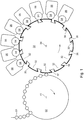
1 eine Vorrichtung zum Bedrucken bzw. zur Dekoration von jeweils eine Mantelfläche aufweisenden Hohlkörpern; -
2 ein Farbwerk insbesondere für die in1 dargestellte Vorrichtung in einer ersten Betriebsstellung; -
3 das Farbwerk insbesondere für die in1 dargestellte Vorrichtung in einer zweiten Betriebsstellung; -
4 eine Schnittdarstellung einer Schlauchpumpe; -
5 eine als Schlauchpumpe ausgebildete Farbpumpe in einem Farbwerk; -
6 eine Rasterwalze mit Rakelbalken, Kammerrakel, Schlauchpumpe und Farbwanne; -
7 eine Reinigungseinrichtung in ihrer Arbeitsstellung zum Reinigen der Mantelfläche einer Rasterwalze; -
8 die Reinigungseinrichtung der7 in einer geöffneten Stellung zum Tausch ihres Reinigungsschwammes; -
9 einen Teil der Anordnung wie in6 , jedoch mit einem Farbrührwerk; -
10 das Farbrührwerk mit seinem Rührorgan an einer ersten Endposition; -
11 das Farbrührwerk mit seinem Rührorgan in einer ersten Arbeitsstellung; -
12 das Farbrührwerk mit seinem Rührorgan an einer zweiten Endposition; -
13 das Farbrührwerk mit seinem Rührorgan in einer zweiten Arbeitsstellung.
-
1 a device for printing or decorating hollow bodies each having a lateral surface; -
2 an inking unit especially for the in1 shown device in a first operating position; -
3rd the inking unit especially for the in1 shown device in a second operating position; -
4th a sectional view of a peristaltic pump; -
5 an ink pump designed as a peristaltic pump in an inking unit; -
6th an anilox roller with doctor bar, chamber doctor blade, hose pump and ink pan; -
7th a cleaning device in its working position for cleaning the outer surface of an anilox roller; -
8th the cleaning facility of the7th in an open position to exchange your cleaning sponge; -
9 part of the arrangement as in6th but with a paint stirrer; -
10 the paint stirrer with its stirrer at a first end position; -
11 the paint stirrer with its stirrer in a first working position; -
12th the paint stirrer with its stirrer at a second end position; -
13th the paint agitator with its agitator in a second working position.
Das Bedrucken insbesondere der Mantelfläche eines Hohlkörpers mit einem z. B. mehrfarbigen Druckmotiv, d. h. mindestens einem Druckbild, erfolgt in einer bevorzugten Ausführung in einem Hochdruckverfahren. Alternative oder zusätzliche Druckverfahren sind z. B. ein Siebdruckverfahren oder ein Offsetdruckverfahren oder ein druckformloses Digitaldruckverfahren. Im Folgenden wird die Erfindung beispielhaft in Verbindung mit einem indirekten Hochdruckverfahren beschrieben, bei dem Druckfarbe zunächst auf ein Drucktuch und erst von dort auf die Mantelfläche eines Hohlkörpers aufgetragen wird. Zur Ausführung dieses speziellen Hochdruckverfahrens wird als Druckform ein Druckklischee auf einer Mantelfläche eines Plattenzylinders angeordnet, weshalb dieser Zylinder mitunter auch als Klischeezylinder bezeichnet wird, insbesondere wenn das Druckklischee z. B. an einer auf dem Zylinder aufgezogenen Sleevehülse angeordnet ist bzw. wird. Der im Weiteren verwendete allgemeinere Begriff „Druckformzylinder“ schließt grundsätzlich beide Ausführungsformen ein, d. h. die klassische Ausführung als Plattenzylinder als auch die Ausführung als ein „Klischeezylinder“. Das für den Druckprozess einsatzfertige Druckklischee ist eine Druckform mit einem Druckrelief, wobei dieses Druckrelief das für den Druckprozess des indirekten Hochdruckverfahrens vorgesehene Druckbild im Gegensatz zum klassischen, d. h. direkten Hochdruckverfahren ungespiegelt wiedergibt, wobei in einem störungsfreien Druckbetrieb nur das Druckrelief an der Übertragung der dem Plattenzylinder vom Farbwerk zugeführten Druckfarbe auf mindestens ein mit diesem Plattenzylinder zusammenwirkenden Drucktuch beteiligt ist. Die auf einem Plattenzylinder aufzuziehende Druckform bzw. das Druckklischee weist einen plattenförmigen vorzugsweise biegsamen Träger endlicher Länge z. B. aus einem Stahlblech auf, wobei auf diesem Träger ein insbesondere flexibler Druckkörper angeordnet ist. Zumindest die in Umfangsrichtung des Plattenzylinders gegenüberliegenden Enden des Trägers können z. B. entsprechend der Krümmung der Mantelfläche des Plattenzylinders vorgebogen oder auch abgewinkelt sein, um eine leichtere Montage der Druckform, d. h. hier insbesondere des Druckklischees auf dem Plattenzylinder zu ermöglichen. Der Träger der Druckform bzw. des Druckklischees hat eine Dicke im Bereich von z. B. 0,2 mm bis 0,3 mm. Das Druckklischee hat einschließlich seines Trägers eine Gesamtdicke im Bereich von z. B. 0,7 mm bis 1,0 mm, vorzugsweise etwa 0,8 mm. Der Druckkörper ist z. B. aus einem Kunststoff gebildet. Der Druckkörper wird zur Herstellung des für den Druckprozess einsatzfähigen Druckklischees z. B. mit einem das Druckbild wiedergebenden Negativfilm belichtet, wobei nicht belichtete Stellen anschließend vom Druckkörper z. B. durch Auswaschen oder mittels eines Lasers entfernt werden.The printing in particular of the outer surface of a hollow body with a z. B. multicolored print motif, d. H. at least one print image takes place in a preferred embodiment in a letterpress process. Alternative or additional printing processes are e.g. B. a screen printing process or an offset printing process or a printing formless digital printing process. In the following, the invention is described by way of example in connection with an indirect letterpress printing process, in which printing ink is first applied to a printing blanket and only from there onto the outer surface of a hollow body. To carry out this special letterpress process, a printing block is arranged as a printing form on a lateral surface of a plate cylinder, which is why this cylinder is sometimes also referred to as a printing block cylinder, especially when the printing block is e.g. B. is or is arranged on a sleeve sleeve pulled onto the cylinder. The more general term “printing forme cylinder” used below basically includes both embodiments, i. H. the classic design as a plate cylinder as well as the design as a "cliché cylinder". The printing block ready for use for the printing process is a printing form with a printing relief, this printing relief being the printing image intended for the printing process of the indirect letterpress printing process, in contrast to the classic, i.e. H. direct letterpress process reproduces unreflected, whereby in a trouble-free printing operation only the printing relief is involved in the transfer of the printing ink supplied to the plate cylinder by the inking unit to at least one printing blanket interacting with this plate cylinder. The printing form or the printing cliché to be drawn up on a plate cylinder has a plate-shaped, preferably flexible, carrier of finite length z. B. from a steel sheet, a particularly flexible pressure body is arranged on this carrier. At least the opposite ends of the carrier in the circumferential direction of the plate cylinder can, for. B. be pre-bent or angled according to the curvature of the lateral surface of the plate cylinder to facilitate assembly of the printing form, d. H. to enable in particular the printing cliché on the plate cylinder. The carrier of the printing form or the printing plate has a thickness in the range of, for. B. 0.2 mm to 0.3 mm. The printing block including its carrier has a total thickness in the range of, for. B. 0.7 mm to 1.0 mm, preferably about 0.8 mm. The pressure body is z. B. formed from a plastic. The printing body is used for the production of the printing cliché z. B. exposed with a negative film reproducing the print image, with unexposed areas then from the printing body z. B. can be removed by washing or by means of a laser.
Eine Vorrichtung zum Bedrucken bzw. zur Dekoration von insbesondere jeweils eine vorzugsweise zylindrische Mantelfläche aufweisenden Hohlkörpern wird auch als ein Dekorator bezeichnet und weist vorzugsweise mehrere, z. B. acht oder zehn oder noch mehr Druckwerke - auch Druckstationen genannt - auf, wobei mindestens eines dieser Druckwerke, in der bevorzugten Ausführung alle diese Druckwerke jeweils einen rotierbaren Druckformzylinder, insbesondere einen als Plattenzylinder ausgebildeten Druckformzylinder und ein Farbwerk aufweisen. Dabei sind die Druckwerke oder Druckstationen und gegebenenfalls auch die Druckformzylinder in dieser Vorrichtung jeweils in einem Gestell gelagert und können in demselben Druckprozess verwendet werden, um auf demselben Hohlkörper ein entsprechend der Zahl der beteiligten Druckwerke bzw. Druckformzylinder mehrfarbiges Druckmotiv auszubilden. Die Lagerung der Druckformzylinder bzw. Plattenzylinder erfolgt jeweils vorzugsweise beidendig, sie kann jedoch auch als eine fliegende Lagerung ausgebildet sein, bei der der betreffende Druckformzylinder bzw. Plattenzylinder nur an einer seiner Stirnseiten jeweils z. B. auf einem vorzugsweise konischen Zapfen gelagert ist. An der Mantelfläche jeden Plattenzylinders ist i.d.R. jeweils nur ein einziges Druckklischee angeordnet, wobei der Träger des Druckklischees den Umfang des betreffenden Plattenzylinders vollständig oder zumindest größtenteils, insbesondere zu mehr als 80% umspannt. Eine in Umfangsrichtung des betreffenden Plattenzylinders gerichtete Länge des Druckkörpers des Druckklischees ist vorzugsweise kürzer ausgebildet als die Umfangslänge des betreffenden Plattenzylinders. Die Druckform bzw. das Druckklischee ist mittels seines Trägers insbesondere magnetisch an der Mantelfläche eines jeden Plattenzylinders angeordnet oder zumindest anordenbar, d. h. die Druckform bzw. das Druckklischee wird dort vorzugsweise magnetisch, d. h. mittels einer magnetischen Haltekraft gehalten. In einer alternativen oder ergänzenden Ausführungsvariante der Vorrichtung zum Bedrucken bzw. zur Dekoration von jeweils eine vorzugsweise zylindrische Mantelfläche aufweisenden Hohlkörpern ist mindestens eines der Druckwerke oder es sind auch mehrere dieser Druckwerke jeweils als ein in einem Digitaldruckverfahren druckformlos druckendes Druckwerk ausgebildet, wobei ein solches Druckwerk insbesondere mindestens einen Inkjetdruckkopf oder einen Laser aufweist.A device for printing or for decorating hollow bodies, in particular each having a preferably cylindrical outer surface, is also referred to as a decorator and preferably has several, e.g. B. eight or ten or even more printing units - also called printing stations - on, at least one of these printing units, in the preferred embodiment, all of these printing units each have a rotatable printing forme cylinder, in particular a printing forme cylinder designed as a plate cylinder and an inking unit. The printing units or printing stations and possibly also the printing forme cylinders in this device are each stored in a frame and can be used in the same printing process to form a multicolored printing motif on the same hollow body according to the number of printing units or printing forme cylinders involved. The printing forme cylinder or plate cylinder is preferably mounted at both ends, but it can also be designed as a floating mounting in which the printing forme cylinder or plate cylinder in question is only z. B. is mounted on a preferably conical pin. On the outer surface of each plate cylinder there is usually only a single printing cliché, the carrier of the printing cliché completely or at least largely, in particular more than 80%, of the circumference of the plate cylinder in question. A length of the printing body of the printing block directed in the circumferential direction of the plate cylinder in question is preferably made shorter than the circumferential length of the plate cylinder in question. The printing forme or the printing cliché is arranged, or at least can be arranged, in particular magnetically on the lateral surface of each plate cylinder by means of its carrier, ie. H. the printing form or the printing cliché is preferably magnetic there, d. H. held by means of a magnetic holding force. In an alternative or additional embodiment of the device for printing or decorating hollow bodies, each preferably having a cylindrical outer surface, at least one of the printing units or several of these printing units are each designed as a printing unit that prints without printing form in a digital printing process, such a printing unit in particular has at least one inkjet print head or a laser.
Die insbesondere gleichzeitige Übertragung von mehreren Druckfarben insbesondere auf die Mantelfläche des betreffenden Hohlkörpers erfordert, dass diese Farbübertragung registerhaltig erfolgt, um im Druckprozess eine gute Druckqualität zu erzielen. Für eine registerhaltige Anordnung der Druckform bzw. des Druckklischees auf der Mantelfläche des betreffenden Druckformzylinders bzw. Plattenzylinders sind in der bevorzugten Ausführung an der Mantelfläche des betreffenden Druckformzylinder bzw. Plattenzylinders vorzugsweise mehrere z. B. in ihrer jeweiligen Position jeweils einstellbare Passstifte vorgesehen, welche in korrespondierende an der Druckform bzw. an dem Druckklischee ausgebildete Aussparungen greifen und der Druckform bzw. dem Druckklischee dadurch bei ihrer bzw. seiner Anordnung auf der Mantelfläche des betreffenden Druckformzylinders bzw. Plattenzylinders dort eine definierte Position geben. Insbesondere kann ein Seitenregister der Druckform bzw. des Druckklischees an einer z. B. geschnittenen Seitenkante dieser Druckform bzw. dieses Druckklischees und ein Umfangsregister dieser Druckform bzw. dieses Druckklischees an einem Anschlag ausgerichtet sein. In einer bevorzugten Ausführung hat jeder Druckformzylinder bzw. Plattenzylinder jeweils einen Durchmesser im Bereich zwischen 100 mm und 150 mm, insbesondere zwischen 120 mm und 130 mm, wobei eine axiale Länge des betreffenden Druckformzylinders bzw. Plattenzylinders jeweils z. B. zwischen 200 mm und 250 mm, insbesondere zwischen 200 mm und 220 mm beträgt. Das auf der Mantelfläche des betreffenden Plattenzylinders anzuordnende Druckklischee hat eine in Axialrichtung des betreffenden Plattenzylinders gerichtete Breite im Bereich von 150 mm bis 200 mm, vorzugsweise etwa 175 mm.The, in particular, simultaneous transfer of several printing inks, in particular to the outer surface of the hollow body in question, requires that this color transfer be carried out in register in order to achieve a good print quality in the printing process. For a register-based arrangement of the printing form or the printing cliché on the outer surface of the relevant printing forme cylinder or plate cylinder, in the preferred embodiment, several z. B. provided in their respective position adjustable dowel pins, which engage in corresponding recesses formed on the printing forme or on the printing cliché and the printing forme or the printing cliché thereby in its or its arrangement on the outer surface of the printing forme cylinder or plate cylinder there one give a defined position. In particular, a page register of the printing form or the printing block can be attached to a z. B. cut side edge of this printing form or this printing cliché and a circumferential register of this printing form or this printing cliché be aligned with a stop. In a preferred embodiment, each printing forme cylinder or plate cylinder each has a diameter in the range between 100 mm and 150 mm, in particular between 120 mm and 130 mm, with an axial length of the printing forme cylinder or plate cylinder in question each z. B. between 200 mm and 250 mm, in particular between 200 mm and 220 mm. The printing block to be arranged on the lateral surface of the plate cylinder in question has a width in the axial direction of the plate cylinder in question in the range from 150 mm to 200 mm, preferably approximately 175 mm.
Jeder der im Druckprozess verwendeten z. B. als Plattenzylinder ausgebildeten Druckformzylinder überträgt mit seiner Druckform bzw. mit seinem Druckklischee jeweils eine bestimmte Druckfarbe auf ein Drucktuch. Bei den verwendeten Druckfarben handelt es sich i.d.R. um vorgemischte, insbesondere auftragsspezifische Sonderfarben, die z. B. hinsichtlich ihrer jeweiligen Verdruckbarkeit in besonderer Weise auf den Werkstoff des zu bedruckenden Hohlkörpers abgestimmt sind, je nachdem, ob eine Oberfläche z. B. aus Aluminium, einem Weißblech oder einem Kunststoff bedruckt wird. Diese auftragsspezifischen Sonderfarben unterscheiden sich zudem üblicherweise auch in ihrem jeweiligen Farbton. In einer bevorzugten Ausführung einer Vorrichtung zum Bedrucken bzw. zur Dekoration von jeweils z. B. eine zylindrische Mantelfläche aufweisenden Hohlkörpern ist eine Druckfarbe von der Druckform bzw. dem Druckklischee auf die Mantelfläche des betreffenden Hohlkörpers übertragende Einrichtung vorgesehen. Diese Druckfarbe übertragende Einrichtung ist vorzugsweise als ein um eine insbesondere horizontale Achse rotierendes Segmentrad ausgebildet, wobei an der Peripherie dieses Segmentrades, d. h. entlang seines Umfangs hintereinander vorzugsweise mehrere, z. B. acht, zehn, zwölf oder noch mehr Drucktücher angeordnet oder zumindest anordenbar sind. Die Druckfarbe übertragende Einrichtung kann als Alternative zum Segmentrad je nach verwendetem Druckverfahren aber auch als eine Dekorationstrommel oder als ein Drucktuchzylinder oder als ein Übertragungszylinder ausgebildet sein, die zumindest beim Drucken jeweils um eine Rotationsachse rotierbar sind. Die Anordnung der Drucktücher am Umfang des Segmentrades erfolgt z. B. dadurch, dass die Drucktücher am Umfang des Segmentrades jeweils z. B. durch eine stoffschlüssige Verbindung, vorzugsweise durch eine Klebung angebracht sind. Die vorzugsweise mehreren Druckformzylinder bzw. Plattenzylinder sind jeweils radial an die an dem Umfang des betreffenden Segmentrades angeordneten Drucktücher angestellt oder zumindest anstellbar. In einer besonders bevorzugten Ausführung einer Vorrichtung zum Bedrucken bzw. zur Dekoration von jeweils eine z. B. zylindrische Mantelfläche aufweisenden Hohlkörpern - d. h. eines Dekorators - ist entlang des Umfangs des Segmentrades hintereinander eine größere Anzahl von Drucktücher angeordnet, als jeweils an das Segmentrad radial angestellte oder zumindest anstellbare Druckformzylinder bzw. Plattenzylinder vorgesehen sind. Die vorzugsweise karussellartig ausgebildete Druckfarbe übertragende Einrichtung, insbesondere das Segmentrad hat einen Durchmesser von z. B. 1.400 mm bis 1.600 mm, vorzugsweise etwa 1.520 mm bis 1.525 mm, und weist bei z. B. acht zugeordneten Druckformzylindern bzw. Plattenzylindern an seinem Umfang hintereinander z. B. zwölf Drucktücher auf. Die Oberfläche eines jeden Druckklischees ist vorzugsweise mit einer größeren Härte ausgebildet als die Härte der jeweiligen Oberfläche der Drucktücher. Die Oberfläche der Drucktücher ist vorzugsweise plan, d. h. ohne eine Profilierung ausgebildet. In einem Betriebszustand, in dem die an dem Druckprozess beteiligten Druckformzylinder bzw. Plattenzylinder jeweils an die Drucktücher des rotativ angetriebenen Segmentrades radial angestellt sind, rollen die jeweiligen Druckformen dieser Druckformzylinder bzw. die jeweiligen Druckklischees dieser Plattenzylinder auf den mit dem Segmentrad bewegten Drucktüchern ab, wobei die Druckklischees zumindest ihr Druckrelief jeweils in das jeweilige Drucktuch eindrücken. Eine Intensität der Eindrückung ist z. B. vor oder zu Beginn eines Druckprozesses z. B. mittels einer Fernbetätigung durch eine Einstellung einer von dem betreffenden Druckformzylinder bzw. Plattenzylinder auf das betreffende Drucktuch des Segmentrades ausgeübten Anpresskraft einstellbar bzw. wird derart eingestellt.Each of the e.g. B. designed as a plate cylinder printing forme cylinder transfers with its printing forme or with its printing cliché in each case a certain printing ink on a printing blanket. The printing inks used are usually premixed, in particular order-specific special colors, e.g. B. with regard to their respective printability in a special way are matched to the material of the hollow body to be printed, depending on whether a surface z. B. made of aluminum, a tinplate or a plastic is printed. These order-specific special colors usually also differ in their respective hue. In a preferred embodiment of a device for printing or for decoration of each z. B. a cylindrical outer surface having hollow bodies, a printing ink is provided from the printing form or the printing block to the surface of the hollow body in question transferring device. This printing ink-transmitting device is preferably designed as a segment wheel rotating about a particularly horizontal axis. H. along its circumference one behind the other preferably several, z. B. eight, ten, twelve or even more printing blankets are arranged or at least can be arranged. As an alternative to the segment wheel, the printing ink-transferring device can, depending on the printing process used, also be designed as a decoration drum or as a blanket cylinder or as a transfer cylinder, each of which can be rotated about an axis of rotation at least during printing. The arrangement of the printing blankets on the circumference of the segment wheel takes place, for. B. in that the printing blankets on the circumference of the segment wheel each z. B. are attached by an integral connection, preferably by an adhesive bond. The preferably several printing forme cylinders or plate cylinders are each adjusted radially or at least adjustable against the printing blankets arranged on the circumference of the segment wheel in question. In a particularly preferred embodiment of a device for printing or decorating one z. B. hollow bodies having cylindrical outer surface - d. H. a decorator - a larger number of printing blankets is arranged one behind the other along the circumference of the segmented wheel than are provided in each case on the segmented wheel radially or at least adjustable printing forme cylinders or plate cylinders. The preferably carousel-like printing ink-transferring device, in particular the segment wheel has a diameter of, for. B. 1,400 mm to 1,600 mm, preferably about 1,520 mm to 1,525 mm, and has at z. B. eight associated printing forme cylinders or plate cylinders on its circumference one behind the other z. B. twelve blankets. The surface of each printing plate is preferably designed with a greater hardness than the hardness of the respective surface of the printing blankets. The surface of the printing blankets is preferably flat, i.e. H. formed without profiling. In an operating state in which the printing form cylinders or plate cylinders involved in the printing process are each positioned radially on the printing blankets of the rotary driven segmented wheel, the respective printing forms of these printing forme cylinders or the respective printing blocks of these plate cylinders roll on the printing blankets moved by the segmented wheel, with the printing plates at least impress their printing relief into the respective printing blanket. An intensity of the impression is e.g. B. before or at the beginning of a printing process z. B. by means of a remote control by setting a pressure force exerted by the relevant printing forme cylinder or plate cylinder on the relevant printing blanket of the segmented wheel, or is set in such a way.
Die hier beispielhaft zu bedruckenden Hohlkörper, z. B. die zu bedruckenden Zweiteildosen, werden z. B. mittels einer die zu bedruckenden Hohlkörper vorzugsweise entlang zumindest eines Teils einer Kreisbahn, d. h. eines Kreisbogens um eine Rotationsachse transportierenden Transporteinrichtung, vorzugsweise mittels mindestens eines Zuführrades, insbesondere mittels eines Mandrelrades kontinuierlich oder in einem eingestellten Takt an jeweils zumindest eines der zur Vorrichtung zum Bedrucken jeweils einer Mantelfläche von Hohlkörpern gehörenden Druckwerke herangeführt und damit in einen Druckbereich von mindestens einem dieser Druckwerke transportiert. Insbesondere werden die zu bedruckenden Hohlkörper mittels der Transporteinrichtung an jeweils zumindest eines der z. B. auf dem Segmentrad angeordneten Drucktücher herangeführt, oder die zu bedruckenden Hohlkörper werden mittels dieser Transporteinrichtung jeweils direkt und unmittelbar, d. h. ohne Zuhilfenahme einer z. B. als Segmentrad ausgebildeten Druckfarbe übertragenden Einrichtung in den jeweiligen Druckbereich von mindestens einem dieser Druckwerke transportiert, was z. B. der Fall ist, wenn das betreffende Druckwerk in einem Direktdruckverfahren, z. B. in einem Inkjetdruckverfahren druckt.The hollow bodies to be printed here by way of example, e.g. B. the two-part cans to be printed, z. B. by means of a transport device that transports the hollow bodies to be printed, preferably along at least part of a circular path, ie a circular arc around an axis of rotation, preferably by means of at least one feed wheel, in particular by means of a mandrel wheel continuously or in a set cycle to in each case at least one of the printing units belonging to the device for printing a lateral surface of hollow bodies and thus transported into a printing area of at least one of these printing units. In particular, the hollow body to be printed by means of the transport device to at least one of the z. B. on the segment wheel arranged printing blankets, or the hollow bodies to be printed are each directly and immediately, ie without the aid of a z. B. designed as a segment wheel printing ink-transmitting device in the respective printing area of at least one of these printing units transported what z. B. is the case when the relevant printing unit in a direct printing process, for. B. prints in an inkjet printing process.
Das wie z. B. das Segmentrad gleichfalls um eine vorzugsweise horizontale Achse rotierende Zuführrad oder Mandrelrad weist konzentrisch zu seiner Umfangslinie in vorzugsweise äquidistanter Verteilung mehrere, z. B. 24 oder 36 Halteeinrichtungen - kurz: Halter - z. B. jeweils in Form eines aus einer Stirnseite des Mandrelrades auskragenden Aufspanndorns oder einer Spindel auf, wobei von jedem Halter jeweils einer der zu bedruckenden Hohlkörper gehalten wird oder zumindest gehalten werden kann. Eine als Mandrelrad ausgebildete Transporteinrichtung wird mitunter auch als ein Drehtisch mit Spindeln bezeichnet. Ein Mandrelrad ist z. B. in der
Zwischen einer Innenwandung des jeweiligen zu bedruckenden Hohlkörpers und der Oberfläche des betreffenden Dorns des Mandrelrades ist vorzugsweise ein Spalt mit einer Weite von weniger als 1 mm, z. B. von 0,2 mm ausgebildet, so dass der zu bedruckende Hohlkörper nicht durch eine Pressung auf dem betreffenden Dorn gehalten wird. Jeder Dorn ist um seine jeweilige Längsachse nahezu reibungslos rotierbar. Jeder der Dorne wird von einem mit dem jeweiligen Dorn zusammenwirkenden Antriebsmittel z. B. mittels Friktion auf eine bestimmte Umfangsgeschwindigkeit eingestellt oder ist zumindest derart einstellbar, so dass jeder von einem Dorn gehaltene zu bedruckende Hohlkörper zusätzlich zur Rotation des Mandrelrades durch eine eigenständig vom Dorn ausgeführte oder zumindest ausführbare Rotation rotierbar ist. Das Aufstülpen des zu bedruckenden Hohlkörpers auf einen der Dorne des Mandrelrades erfolgt vorzugsweise während einer Stillstandsphase des betreffenden Dorns, wobei der betreffende Dorn während seiner Stillstandsphase keine Drehbewegung um seine eigene Längsachse ausführt. Die Belegung eines jeden Dorns mit einem zu bedruckenden Hohlkörper wird vorzugsweise überprüft, z. B. berührungslos mit einem Sensor. Bei einer fehlenden Belegung eines Dorns mit einem zu bedruckenden Hohlkörper wird das Mandrelrad z. B. derart bewegt, dass ein Kontakt des betreffenden freien Dorns und gegebenenfalls noch einiger weniger weiterer Dorne mit einem Drucktuch des Segmentrades zuverlässig vermieden wird.Between an inner wall of the respective hollow body to be printed and the surface of the relevant mandrel of the mandrel wheel, there is preferably a gap with a width of less than 1 mm, e.g. B. formed of 0.2 mm, so that the hollow body to be printed is not held by pressing on the mandrel in question. Each mandrel can be rotated almost smoothly about its respective longitudinal axis. Each of the mandrels is driven by a drive means cooperating with the respective mandrel, e.g. B. is set to a certain circumferential speed by means of friction or is at least adjustable so that each hollow body to be printed on held by a mandrel can be rotated in addition to the rotation of the mandrel wheel by an independently executed or at least executable rotation by the mandrel. The hollow body to be printed is slipped onto one of the mandrels of the mandrel wheel preferably during a standstill phase of the relevant mandrel, the relevant mandrel not executing any rotary movement about its own longitudinal axis during its standstill phase. The occupancy of each mandrel with a hollow body to be printed is preferably checked, e.g. B. contactless with a sensor. If there is no assignment of a mandrel with a hollow body to be printed, the mandrel wheel z. B. moved in such a way that contact of the free mandrel in question and possibly a few other mandrels with a printing blanket of the segment wheel is reliably avoided.
Zu bedruckende Zweiteildosen werden vor ihrer Zuführung z. B. zum Mandrelrad in einer dem Mandrelrad vorgelagerten Bearbeitungsstation hergestellt, z. B. aus einer Ronde tiefgezogen. In einer weiteren Bearbeitungsstation wird an jeder Zweiteildose ihr Rand an ihrer offenen Stirnseite beschnitten. Jede Zweiteildose wird in weiteren Bearbeitungsstationen z. B. gewaschen, insbesondere ihr Inneres ausgewaschen, gegebenenfalls werden die Innenwandung und der Boden der betreffenden Zweiteildose auch lackiert. Zumindest die äußere Mantelfläche einer jeden Zweiteildose wird z. B. grundiert, insbesondere mit einer weißen Grundierung. Nach dem Bedrucken ihrer Mantelfläche wird jede Zweiteildose von ihrem jeweiligen Halter z. B. am Mandrelrad z. B. durch Druckluft oder durch einen vorzugsweise schaltbaren Magneten abgenommen und mindestens einer dem Mandrelrad nachgeordneten Bearbeitungsstation zugeführt, z. B. einer Lackierstation zum Lackieren der äußeren Mantelfläche einer jeden bedruckten Zweiteildose und/oder einer Randbearbeitungsstation. Die bedruckten Zweiteildosen durchlaufen insbesondere einen Trockner, z. B. einen Heißlufttrockner, um die mindestens eine auf ihre jeweilige Mantelfläche aufgebrachte Druckfarbe auszuhärten.Two-part cans to be printed are z. B. to the mandrel wheel in a machining station upstream of the mandrel wheel, z. B. deep-drawn from a round blank. In a further processing station, the edge of each two-piece can is trimmed on its open end. Each two-part box is z. B. washed, in particular their inside washed out, if necessary, the inner wall and the bottom of the two-part box in question are also painted. At least the outer surface of each two-part box is z. B. primed, especially with a white primer. After printing on its outer surface, each two-part can is held by its respective holder, for. B. on the mandrel wheel z. B. removed by compressed air or by a preferably switchable magnet and fed to at least one processing station downstream of the mandrel wheel, z. B. a painting station for painting the outer surface of each printed two-piece can and / or an edge processing station. The printed two-part cans go through in particular a dryer, for. B. a hot air dryer in order to cure the at least one printing ink applied to its respective lateral surface.
Der Druckprozess zum Bedrucken insbesondere der jeweiligen Mantelfläche von z. B. an dem Mandrelrad gehaltenen Hohlkörpern, insbesondere Zweiteildosen, beginnt damit, dass alle für das auf der jeweiligen Mantelfläche des Hohlkörpers zu druckende Druckbild erforderlichen Druckfarben jeweils z. B. von dem jeweiligen Druckklischee der z. B. an das Segmentrad angestellten Plattenzylinder auf dasselbe von einem der am Umfang des Segmentrades angeordneten Drucktücher aufgetragen werden. Das betreffende derart mit allen erforderlichen Druckfarben eingefärbte Drucktuch überträgt sodann in einem Berührungskontakt zwischen Drucktuch und der Mantelfläche des zu bedruckenden Hohlkörpers diese Druckfarben gleichzeitig während einer einzigen Umdrehung des auf einem der Dorne des Mandrelrades gehaltenen zu bedruckenden Hohlkörpers um seine Längsachse auf die Mantelfläche dieses Hohlkörpers. Während der Übertragung der Druckfarben vom Drucktuch auf die Mantelfläche des Hohlkörpers rotiert der z. B. von einem der Dorne des Mandrelrades gehaltene zu bedruckende Hohlkörper mit einer betragsgleichen Umfangsgeschwindigkeit wie das betreffende z. B. am Umfang des Segmentrades angeordnete Drucktuch. Die jeweiligen Umfangsgeschwindigkeiten von Hohlkörper und Drucktuch bzw. Segmentrad sind demnach miteinander synchronisiert, wobei der z. B. auf einem der Dorne des Mandrelrades gehaltene zu bedruckende Hohlkörper insbesondere durch ein auf den betreffenden Dorn wirkendes Antriebsmittel z. B. aus seinem Stillstand insbesondere bis zum Erreichen der Umfangsgeschwindigkeit z. B. des Segmentrades entsprechend beschleunigt wird, wobei die Umfangsgeschwindigkeit des betreffenden Dorns des Mandrelrades vorzugsweise beginnend ab einer ersten Kontaktstelle des zu bedruckenden Hohlkörpers mit dem betreffenden Drucktuch während des Abrollens seiner Mantelfläche auf einer Strecke z. B. von den ersten 50 mm von der Umfangslänge des Drucktuches mit der Umfangsgeschwindigkeit des Segmentrades synchronisiert wird. In der bevorzugten Ausführung gibt das das betreffende Drucktuch tragende Segmentrad die z. B. an dem jeweiligen Dorn des Mandrelrades einzustellende Umfangsgeschwindigkeit vor. Auch die Umfangsgeschwindigkeit des die Druckform tragenden Druckformzylinders oder des das Druckklischee tragenden Plattenzylinders wird oder ist vorzugsweise in Abhängigkeit von der Umfangsgeschwindigkeit z. B. des Segmentrades eingestellt. In der bevorzugten Ausführung sind das Mandrelrad und das Segmentrad jeweils durch einen eigenen Antrieb einzeln angetrieben und von einer Steuereinheit in ihrem jeweiligen Rotationsverhalten gesteuert oder geregelt.The printing process for printing in particular the respective outer surface of z. B. on that Mandrel wheel held hollow bodies, in particular two-part cans, begins with the fact that all the printing inks required for the print image to be printed on the respective outer surface of the hollow body, e.g. B. from the respective printing cliché of the z. B. on the segment wheel employed plate cylinder can be applied to the same by one of the printing blankets arranged on the circumference of the segment wheel. The relevant printing blanket colored with all the necessary printing inks then transfers these printing inks simultaneously during a single rotation of the hollow body to be printed on one of the mandrels of the mandrel wheel around its longitudinal axis to the circumferential surface of this hollow body in a touch contact between the printing blanket and the outer surface of the hollow body to be printed. During the transfer of the printing inks from the blanket to the outer surface of the hollow body, the z. B. held by one of the mandrels of the mandrel wheel to be printed hollow body with a circumferential speed of the same amount as the relevant z. B. arranged on the circumference of the segment wheel printing blanket. The respective circumferential speeds of the hollow body and printing blanket or segment wheel are therefore synchronized with one another, the z. B. held on one of the mandrels of the mandrel wheel to be printed hollow body in particular by a drive means acting on the mandrel in question z. B. from its standstill in particular until reaching the peripheral speed z. B. the segment wheel is accelerated accordingly, the peripheral speed of the mandrel in question of the mandrel wheel, preferably starting from a first contact point of the hollow body to be printed with the printing blanket in question during the rolling of its outer surface on a distance z. B. is synchronized by the first 50 mm of the circumferential length of the blanket with the circumferential speed of the segment wheel. In the preferred embodiment, the segment wheel carrying the printing blanket in question is the z. B. to be set on the respective mandrel of the mandrel wheel circumferential speed. The peripheral speed of the printing forme cylinder carrying the printing form or of the plate cylinder carrying the printing block is or is preferably depending on the peripheral speed, for. B. set the segment wheel. In the preferred embodiment, the mandrel wheel and the segment wheel are each individually driven by their own drive and their respective rotational behavior is controlled or regulated by a control unit.
Insbesondere mit Bezug auf die bisher beschriebene Vorrichtung zum Bedrucken bzw. zur Dekoration insbesondere von jeweils eine z. B. zylindrische Mantelfläche aufweisenden Hohlkörpern werden nachfolgend beispielhaft noch verschiedene Einzelheiten erläutert.
Der Plattenzylinder
Die Farbauftragswalze
In der bevorzugten Ausführung weist zumindest die Rasterwalze
Das Farbreservoir des Farbwerks
Nachdem die Rasterwalze
In einer sehr vorteilhaften Ausbildung der Vorrichtung zum Bedrucken von Hohlkörpern
Die jeweilige Anstellung und/oder Abstellung von Druckformzylinder bzw. Plattenzylinder
In der bevorzugten Ausführung ist auch die Farbauftragswalze
In der bevorzugten Ausführung ist ein jedes der an dem Segmentrad
Beim Bedrucken oder Dekoration von insbesondere jeweils eine vorzugsweise zylindrische Mantelfläche aufweisenden Hohlkörpern, insbesondere von Dosen, geht der Trend immer stärker zu Kleinproduktionen, was im Dosendruck eine Produktion von weniger als 100.000 Dosen, vorzugsweise sogar nur 50.000 Dosen oder weniger pro Serie bedeutet. Kunden erwarten und fordern eine immer individuellere Gestaltung des insbesondere auf der Mantelfläche des betreffenden Hohlkörpers aufzubringenden Druckbildes. Dies bedingt mehrere Wechsel der Druckfarben an der Druckmaschine, d. h. an dem Dekorator pro Arbeitsschicht. Mitunter hat dieser Kundenwunsch zur Folge, dass bei einer Produktionsgeschwindigkeit zwischen 1.500 und 2.500 Stück (Dosen) pro Minute, vorzugsweise zwischen 1.800 und 2.200 Stück (Dosen) pro Minute an der Druckmaschine die Druckfarben praktisch stündlich zu wechseln sind, weil die Druckfarben zumeist als auftragsspezifische Sonderfarben ausgebildet sind und sich damit z. B. im Farbton produktionsabhängig voneinander unterscheiden. Nun ist ein Dekorator nur eine von mehreren Arbeitsstationen in der Produktionsanlage zur Fertigung solcher Hohlkörper. Üblicherweise weist eine solche Produktionsanlage eine Vielzahl von funktional miteinander verketteten, d. h. im Produktionsprozess aufeinander abgestimmten Arbeitsstationen auf. Es ist nicht erwünscht, dass zur Ausführung einer Umrüstung an einem Dekorator aufgrund eines Produktionswechsels die gesamte Produktionsanlage mit all ihren Arbeitsstationen zum Stillstand kommt. Vielmehr sind an verschiedenen Stellen in der Produktionsanlage jeweils ein Zwischenspeicher vorgesehen, in welche die übrigen Arbeitsstationen die von ihnen bearbeiteten und zur Produktion von dekorierten Hohlkörpern erforderlichen Werkstücke zwischenspeichern können, bis die gesamte Produktionsanlage nach der Umrüstung einer einzelnen Arbeitsstation wie einem Dekorator wieder durchgängig produktionsbereit ist. Zum Umrüsten des Dekorators steht daher praktisch maximal nur derjenige Zeitraum zur Verfügung, bis ein diesem Dekorator vorgeordneter Zwischenspeicher durch die fortgesetzte Produktion vorgeordneter Arbeitsstationen gefüllt ist. Dieser Zeitraum beträgt z. B. höchstens 15 bis 20 Minuten. Um in einer gattungsgemäßen Produktionsanlage rasche Produktionswechsel realisieren zu können, sind daher auch zwingend an einem Dekorator kurze Rüstzeiten erforderlich. Dies gilt insbesondere auch für ein in einem Dekorator angeordnetes Druckwerk und/oder Farbwerk, wobei zu beachten ist, dass ein solcher Dekorator z. B. acht bis zwölf Druckwerke und/oder Farbwerke aufweist, so dass bei einem Produktionswechsel unter Umständen auch eine entsprechende Anzahl von Druckfarben ausgewechselt werden muss. Die Realisierung einer schnellen Umrüstung wird noch dadurch erschwert, dass gerade beim Dekorieren von Hohlkörpern, wie z. B. Dosen, d. h. insbesondere beim Bedrucken ihrer jeweiligen Mantelfläche, hochviskose Druckfarben verwendet werden, so dass ein diese Druckfarben verwendendes Farbwerk und/oder Druckwerk nur schwer, d. h. mit erhöhtem Aufwand zu reinigen ist. Denn diese Druckfarben sind aufgrund ihrer Zähigkeit, d. h. geringen Fließfähigkeit und ihres Haftvermögens nicht einfach von farbführenden Bauteilen zu entfernen. Überdies sind die am häufigsten verwendeten Druckfarben, d. h. die auftragsspezifischen Sonderfarben im Vergleich zu anderen Druckfarben, d. h. zu Standarddruckfarben oder zu Druckfarben für andere Druckverfahren wie z. B. dem Offsetdruck recht teuer, so dass mit diesen auftragsspezifischen Druckfarben schon aus wirtschaftlichen Gründen sparsam umzugehen ist und es sich verbietet, im Farbwerk befindliche Restbestände einfach zu entsorgen statt aufzufangen und in einer späteren Produktion weiter zu verwenden. Vor diesem Hintergrund, nämlich der Forderung nach kurzen Umrüstzeiten und dem Umstand, dass die verwendeten Druckfarben teuer sind und ein mit diesen Druckfarben eingefärbtes Farbwerk und/oder Druckwerk nur schwer zu reinigen ist, werden nun folgende Lösungen vorgeschlagen.When printing or decorating hollow bodies, in particular cans, which preferably have a cylindrical outer surface, the trend is increasingly towards small-scale productions, which in can printing means a production of less than 100,000 cans, preferably even only 50,000 cans or less per series. Customers expect and demand an ever more individual design of the print image to be applied, in particular, to the outer surface of the hollow body in question. This requires several changes of the printing inks on the printing machine, ie on the decorator per work shift. Sometimes this customer request has the consequence that at a production speed between 1,500 and 2,500 pieces (cans) per minute, preferably between 1,800 and 2,200 pieces (cans) per minute on the printing machine, the printing inks have to be changed practically every hour, because the printing inks are mostly job-specific Special colors are designed and thus z. B. differ in color depending on the production. Now a decorator is just one of several workstations in the production plant for manufacturing such hollow bodies. Such a production plant usually has a large number of workstations that are functionally linked to one another, ie, workstations that are coordinated with one another in the production process. It is not desirable for the entire production plant with all of its workstations to come to a standstill in order to carry out a conversion on a decorator due to a production change. Rather, an intermediate storage device is provided at various points in the production plant, in which the other workstations can temporarily store the workpieces they have processed and required for the production of decorated hollow bodies, until the entire production plant is continuously ready for production again after a single workstation such as a decorator has been converted . For converting the decorator, therefore, there is practically only the maximum time available until an intermediate storage device arranged upstream of this decorator is filled by the continued production of upstream workstations. This period is z. B. a maximum of 15 to 20 minutes. In order to be able to implement rapid production changes in a generic production plant, short set-up times are therefore also absolutely necessary on a decorator. This also applies in particular to a printing unit and / or inking unit arranged in a decorator, it being important to note that such a decorator z. B. has eight to twelve printing units and / or inking units, so that in the event of a production change, a corresponding number of printing inks may also have to be replaced. The realization of a quick conversion is made even more difficult by the fact that especially when decorating hollow bodies, such as. B. cans, ie in particular when printing their respective outer surface, highly viscous printing inks are used, so that an inking unit and / or printing unit using these printing inks can only be cleaned with difficulty, ie with increased effort. This is because these printing inks are not easy to remove from ink-carrying components due to their toughness, ie low flowability and adhesion. In addition, the most frequently used printing inks, ie the order-specific special colors compared to other printing inks, ie to standard printing inks or to printing inks for other printing processes such as e.g. B. offset printing is quite expensive, so that these order-specific printing inks have to be used sparingly for economic reasons and it is forbidden to simply use remaining stocks in the inking unit to be disposed of instead of being collected and reused in a later production process. Against this background, namely the requirement for short changeover times and the fact that the printing inks used are expensive and an inking unit and / or printing unit colored with these printing inks can only be cleaned with difficulty, the following solutions are now proposed.
Es wird ein Farbwerk
Wie bereits beschrieben und in der
Zu den farbführenden Bauteilen eines insbesondere als ein Kurzfarbwerk ausgebildeten Farbwerks
Es wird daher vorgeschlagen, dass eine Reinigungseinrichtung
Die perspektivischen Darstellungen der
Den
Am stirnseitigen zweiten Ende der Farbwanne
Nachdem das Rührorgan
BezugszeichenlisteList of reference symbols
- 0101
- Hohlkörper; ZweiteildoseHollow body; Two-part box
- 0202
- MandrelradMandrel wheel
- 0303
- SegmentradSegment wheel
- 0404
- Druckformzylinder; PlattenzylinderPrinting form cylinder; Plate cylinder
- 0505
- --
- 0606
- FarbwerkInking unit
- 0707
- FarbauftragswalzeInking roller
- 0808
- RasterwalzeAnilox roller
- 0909
- RakelkammerDoctor blade chamber
- 1010
- --
- 1111
- Motorengine
- 1212th
- Motorengine
- 1313th
- ReiterwalzeRider roll
- 1414th
- PlattenwechslerRecord changer
- 1515th
- --
- 1616
- AuflageflächeSupport surface
- 1717th
- Traversetraverse
- 1818th
- Hebelanordnung, ersteLever assembly, first
- 1919th
- Drehachse, ersteAxis of rotation, first
- 2020th
- --
- 2121
- Antrieb, ersterDrive, first
- 2222nd
- Anschlag, ersterStop, first
- 2323
- Hebelanordnung, zweiteLever assembly, second
- 2424
- Hebelanordnung, dritte; GestellwandLever assembly, third; Rack wall
- 2525th
- --
- 2626th
- Drehachse, zweiteAxis of rotation, second
- 2727
- Antrieb, zweiterDrive, second
- 2828
- Antrieb, dritterDrive, third
- 2929
- Anschlagssystem, erstesStop system, first
- 3030th
- --
- 3131
- Anschlagssystem, zweitesStop system, second
- 3232
-
Segment (
03 )Segment (03 ) - 3333
- DrucktuchPrinting blanket
- 3434
-
Rotationsachse (
03 )Axis of rotation (03 ) - 3535
- --
- 3636
- AussparungRecess
- 3737
-
Kante (
33 )Edge (33 ) - 3838
-
Einhängeschenkel (
33 )Suspension leg (33 ) - 3939
-
Kante (
36 )Edge (36 ) - 4040
- --
- 4141
-
Rotationsachse (
02 )Axis of rotation (02 ) - 4242
- Farbpumpe; SchlauchpumpePaint pump; Peristaltic pump
- 4343
- Rotorrotor
- 4444
- Nockencam
- 4545
- --
- 4646
- Motorengine
- 4747
- PumpengehäusePump housing
- 4848
- SchlauchelementHose element
- 4949
- VerbindungselementConnecting element
- 5050
- --
- 5151
- Behälter zur Bereitstellung von Druckfarbe; FarbwanneContainers for providing printing ink; Paint tray
- 5252
- RakelbalkenSqueegee beam
- 5353
- ReinigungseinrichtungCleaning facility
- 5454
- Schwammsponge
- 5555
- --
- 5656
- LeitungssystemPiping system
- 5757
- Halterholder
- 5858
- EinschubgriffSlide-in handle
- 5959
- FarbrührwerkPaint agitator
- 6060
- --
- 6161
- RührorganAgitator
- 6262
- Antriebdrive
- 6363
- Achse axis
- d04d04
- Außendurchmesserouter diameter
- d07d07
- Außendurchmesserouter diameter
- d08d08
- Außendurchmesserouter diameter
- GG
- GeradeStraight
ZITATE ENTHALTEN IN DER BESCHREIBUNGQUOTES INCLUDED IN THE DESCRIPTION
Diese Liste der vom Anmelder aufgeführten Dokumente wurde automatisiert erzeugt und ist ausschließlich zur besseren Information des Lesers aufgenommen. Die Liste ist nicht Bestandteil der deutschen Patent- bzw. Gebrauchsmusteranmeldung. Das DPMA übernimmt keinerlei Haftung für etwaige Fehler oder Auslassungen.This list of the documents listed by the applicant was generated automatically and is included solely for the better information of the reader. The list is not part of the German patent or utility model application. The DPMA assumes no liability for any errors or omissions.
Zitierte PatentliteraturPatent literature cited
- WO 2012/148576 A1 [0002, 0007]WO 2012/148576 A1 [0002, 0007]
- WO 2011/051072 A1 [0008]WO 2011/051072 A1 [0008]
- EP 0501677 A1 [0009]EP 0501677 A1 [0009]
- DE 3933388 A1 [0010]DE 3933388 A1 [0010]
- EP 1165318 A1 [0021]EP 1165318 A1 [0021]
- WO 2011/156052 A1 [0021]WO 2011/156052 A1 [0021]
- EP 1132207 A1 [0021]EP 1132207 A1 [0021]
Claims (5)
Priority Applications (1)
| Application Number | Priority Date | Filing Date | Title |
|---|---|---|---|
| DE102019123632.0A DE102019123632A1 (en) | 2019-09-04 | 2019-09-04 | Container for providing printing ink in an inking unit of a printing machine |
Applications Claiming Priority (1)
| Application Number | Priority Date | Filing Date | Title |
|---|---|---|---|
| DE102019123632.0A DE102019123632A1 (en) | 2019-09-04 | 2019-09-04 | Container for providing printing ink in an inking unit of a printing machine |
Publications (1)
| Publication Number | Publication Date |
|---|---|
| DE102019123632A1 true DE102019123632A1 (en) | 2021-03-04 |
Family
ID=74564847
Family Applications (1)
| Application Number | Title | Priority Date | Filing Date |
|---|---|---|---|
| DE102019123632.0A Pending DE102019123632A1 (en) | 2019-09-04 | 2019-09-04 | Container for providing printing ink in an inking unit of a printing machine |
Country Status (1)
| Country | Link |
|---|---|
| DE (1) | DE102019123632A1 (en) |
Citations (12)
| Publication number | Priority date | Publication date | Assignee | Title |
|---|---|---|---|---|
| DE3014904A1 (en) * | 1980-04-18 | 1981-11-05 | Hauni-Werke Körber & Co KG, 2050 Hamburg | METHOD AND ARRANGEMENT FOR TRANSFERRING COLOR FROM A COMMERCIAL COLOR CONTAINER TO A CIGARETTE PAPER STRIP |
| DE3933388A1 (en) * | 1988-10-26 | 1990-05-03 | Polygraph Leipzig | COLOR TUNER |
| DE4026729A1 (en) * | 1990-08-24 | 1992-02-27 | Man Miller Druckmasch | Inking system for rotary printing machine - has bag to contain ink and roller to squeeze ink out of bag |
| EP0501677A1 (en) * | 1991-02-27 | 1992-09-02 | J & C MOORES LTD | Ink agitating apparatus |
| DE19515621A1 (en) * | 1995-04-28 | 1996-10-31 | Fischer & Krecke Gmbh & Co | Inking system for printing machines |
| EP1132207A1 (en) * | 2000-03-02 | 2001-09-12 | HINTERKOPF GmbH | Transfer device for hollow articles to be printed or already printed in a printing machine |
| EP1165318A1 (en) * | 1999-02-10 | 2002-01-02 | Sequa Corporation | Mandrel carrier for high speed can decorators |
| DE10236311A1 (en) * | 2002-08-08 | 2004-02-26 | Technotrans Ag | Device for supplying ink to ink reservoir of printer has tub-shaped container of ink with interior emptied through outlet hole associated with cover element with through opening and associated valve assembly to close and prevent dripping |
| DE102004033309A1 (en) * | 2004-07-08 | 2006-02-02 | Technotrans Ag | Device for delivery of paste substances especially printing ink in press has guide cylinder fitted in holder, and cartridge as flexible tubular film connected by one end to bottom piece which includes valve opening into cartridge |
| WO2011051072A1 (en) * | 2009-10-28 | 2011-05-05 | Koenig & Bauer Aktiengesellschaft | Pressure setting device of a chambered doctor blade system |
| WO2011156052A1 (en) * | 2010-06-09 | 2011-12-15 | Stolle Machinery Company | Self-aligning pivotable mandrel assembly |
| WO2012148576A1 (en) * | 2011-04-27 | 2012-11-01 | Stolle Machinery Company, Llc | Can decorator machine, ink station assembly therefor, and can decorating method employing same |
-
2019
- 2019-09-04 DE DE102019123632.0A patent/DE102019123632A1/en active Pending
Patent Citations (12)
| Publication number | Priority date | Publication date | Assignee | Title |
|---|---|---|---|---|
| DE3014904A1 (en) * | 1980-04-18 | 1981-11-05 | Hauni-Werke Körber & Co KG, 2050 Hamburg | METHOD AND ARRANGEMENT FOR TRANSFERRING COLOR FROM A COMMERCIAL COLOR CONTAINER TO A CIGARETTE PAPER STRIP |
| DE3933388A1 (en) * | 1988-10-26 | 1990-05-03 | Polygraph Leipzig | COLOR TUNER |
| DE4026729A1 (en) * | 1990-08-24 | 1992-02-27 | Man Miller Druckmasch | Inking system for rotary printing machine - has bag to contain ink and roller to squeeze ink out of bag |
| EP0501677A1 (en) * | 1991-02-27 | 1992-09-02 | J & C MOORES LTD | Ink agitating apparatus |
| DE19515621A1 (en) * | 1995-04-28 | 1996-10-31 | Fischer & Krecke Gmbh & Co | Inking system for printing machines |
| EP1165318A1 (en) * | 1999-02-10 | 2002-01-02 | Sequa Corporation | Mandrel carrier for high speed can decorators |
| EP1132207A1 (en) * | 2000-03-02 | 2001-09-12 | HINTERKOPF GmbH | Transfer device for hollow articles to be printed or already printed in a printing machine |
| DE10236311A1 (en) * | 2002-08-08 | 2004-02-26 | Technotrans Ag | Device for supplying ink to ink reservoir of printer has tub-shaped container of ink with interior emptied through outlet hole associated with cover element with through opening and associated valve assembly to close and prevent dripping |
| DE102004033309A1 (en) * | 2004-07-08 | 2006-02-02 | Technotrans Ag | Device for delivery of paste substances especially printing ink in press has guide cylinder fitted in holder, and cartridge as flexible tubular film connected by one end to bottom piece which includes valve opening into cartridge |
| WO2011051072A1 (en) * | 2009-10-28 | 2011-05-05 | Koenig & Bauer Aktiengesellschaft | Pressure setting device of a chambered doctor blade system |
| WO2011156052A1 (en) * | 2010-06-09 | 2011-12-15 | Stolle Machinery Company | Self-aligning pivotable mandrel assembly |
| WO2012148576A1 (en) * | 2011-04-27 | 2012-11-01 | Stolle Machinery Company, Llc | Can decorator machine, ink station assembly therefor, and can decorating method employing same |
Similar Documents
| Publication | Publication Date | Title |
|---|---|---|
| EP3169521B1 (en) | Device for printing hollow articles | |
| EP3169520B1 (en) | Device with several printing units each for printing on hollow bodies | |
| EP3169519B1 (en) | Printing unit with plate cylinder and plate changing device | |
| DE102019123631A1 (en) | Inking unit of a printing press | |
| DE102019123634A1 (en) | Ink stirrer for circulating printing ink in an ink pan arranged in an inking unit of a printing machine and inking unit of a printing machine with this ink stirrer | |
| EP3408100B1 (en) | Device for printing hollow bodies, and method for operating said device | |
| EP3487708A1 (en) | Device and method for printing hollow bodies, comprising a linearly adjustable supply device | |
| DE102016201140B4 (en) | Method for operating a device having a segment wheel for printing hollow bodies | |
| EP3169522B1 (en) | Inking unit of a printing unit | |
| WO2016008701A1 (en) | Inking unit of a printing unit | |
| DE102014213813B4 (en) | Device for printing in each case a lateral surface of hollow bodies | |
| DE102019123632A1 (en) | Container for providing printing ink in an inking unit of a printing machine | |
| DE102019123633A1 (en) | Inking unit of a printing press | |
| WO2018149652A1 (en) | Device for printing on hollow bodies | |
| DE102016201139B4 (en) | Device for printing hollow bodies | |
| DE102014213807B4 (en) | Apparatus for printing on each of a lateral surface having hollow bodies | |
| DE102014213812B3 (en) | Device for arranging a printing form cylinder and an inking unit of a printing unit | |
| DE102022114616A1 (en) | Inking unit of a device for printing hollow bodies | |
| DE102014213811A1 (en) | Printing unit with a printing forme cylinder | |
| EP3582969A1 (en) | Method for operating a device for printing hollow bodies | |
| DE102023124564A1 (en) | Inking unit in a hollow body printing press | |
| DE102017201921B4 (en) | Device for printing hollow bodies | |
| DE102023124568A1 (en) | Inking unit in a hollow body printing press | |
| DE102023124567A1 (en) | Inking unit in a hollow body printing press | |
| DE102014213804A1 (en) | Inking unit of a printing unit |
Legal Events
| Date | Code | Title | Description |
|---|---|---|---|
| R012 | Request for examination validly filed | ||
| R016 | Response to examination communication |