DE102019122064A1 - Processing device for laser processing of a workpiece, parts set for a processing device for laser processing of a workpiece and method for laser processing of a workpiece - Google Patents
Processing device for laser processing of a workpiece, parts set for a processing device for laser processing of a workpiece and method for laser processing of a workpiece Download PDFInfo
- Publication number
- DE102019122064A1 DE102019122064A1 DE102019122064.5A DE102019122064A DE102019122064A1 DE 102019122064 A1 DE102019122064 A1 DE 102019122064A1 DE 102019122064 A DE102019122064 A DE 102019122064A DE 102019122064 A1 DE102019122064 A1 DE 102019122064A1
- Authority
- DE
- Germany
- Prior art keywords
- laser beam
- cooling
- processing
- actuator
- machining
- Prior art date
- Legal status (The legal status is an assumption and is not a legal conclusion. Google has not performed a legal analysis and makes no representation as to the accuracy of the status listed.)
- Ceased
Links
- 238000000034 method Methods 0.000 title claims abstract description 16
- 238000012545 processing Methods 0.000 title claims description 144
- 238000003754 machining Methods 0.000 claims abstract description 113
- 238000001816 cooling Methods 0.000 claims abstract description 103
- 239000012809 cooling fluid Substances 0.000 claims abstract description 75
- 230000003287 optical effect Effects 0.000 claims abstract description 26
- 230000010355 oscillation Effects 0.000 claims description 28
- 238000003698 laser cutting Methods 0.000 claims description 10
- 230000001678 irradiating effect Effects 0.000 claims description 2
- 239000007788 liquid Substances 0.000 claims description 2
- 238000007493 shaping process Methods 0.000 description 26
- 238000009826 distribution Methods 0.000 description 11
- 230000004048 modification Effects 0.000 description 10
- 238000012986 modification Methods 0.000 description 10
- 238000011161 development Methods 0.000 description 9
- 230000007774 longterm Effects 0.000 description 9
- 238000011109 contamination Methods 0.000 description 8
- 239000000463 material Substances 0.000 description 8
- 230000003068 static effect Effects 0.000 description 8
- 238000005520 cutting process Methods 0.000 description 6
- 239000011521 glass Substances 0.000 description 6
- HFGPZNIAWCZYJU-UHFFFAOYSA-N lead zirconate titanate Chemical class [O-2].[O-2].[O-2].[O-2].[O-2].[Ti+4].[Zr+4].[Pb+2] HFGPZNIAWCZYJU-UHFFFAOYSA-N 0.000 description 5
- 239000012528 membrane Substances 0.000 description 5
- 230000001681 protective effect Effects 0.000 description 5
- 239000002826 coolant Substances 0.000 description 4
- RYGMFSIKBFXOCR-UHFFFAOYSA-N Copper Chemical compound [Cu] RYGMFSIKBFXOCR-UHFFFAOYSA-N 0.000 description 3
- 239000000919 ceramic Substances 0.000 description 3
- 230000003749 cleanliness Effects 0.000 description 3
- 239000011248 coating agent Substances 0.000 description 3
- 238000000576 coating method Methods 0.000 description 3
- 229910052802 copper Inorganic materials 0.000 description 3
- 239000010949 copper Substances 0.000 description 3
- 230000000694 effects Effects 0.000 description 3
- 239000012530 fluid Substances 0.000 description 3
- 239000002184 metal Substances 0.000 description 3
- 229910052751 metal Inorganic materials 0.000 description 3
- 230000008569 process Effects 0.000 description 3
- VYPSYNLAJGMNEJ-UHFFFAOYSA-N Silicium dioxide Chemical compound O=[Si]=O VYPSYNLAJGMNEJ-UHFFFAOYSA-N 0.000 description 2
- 230000003044 adaptive effect Effects 0.000 description 2
- 239000000835 fiber Substances 0.000 description 2
- 229910052451 lead zirconate titanate Inorganic materials 0.000 description 2
- 229910044991 metal oxide Inorganic materials 0.000 description 2
- 150000004706 metal oxides Chemical class 0.000 description 2
- 239000002245 particle Substances 0.000 description 2
- HBMJWWWQQXIZIP-UHFFFAOYSA-N silicon carbide Chemical compound [Si+]#[C-] HBMJWWWQQXIZIP-UHFFFAOYSA-N 0.000 description 2
- 229910010271 silicon carbide Inorganic materials 0.000 description 2
- XLYOFNOQVPJJNP-UHFFFAOYSA-N water Substances O XLYOFNOQVPJJNP-UHFFFAOYSA-N 0.000 description 2
- BUHVIAUBTBOHAG-FOYDDCNASA-N (2r,3r,4s,5r)-2-[6-[[2-(3,5-dimethoxyphenyl)-2-(2-methylphenyl)ethyl]amino]purin-9-yl]-5-(hydroxymethyl)oxolane-3,4-diol Chemical compound COC1=CC(OC)=CC(C(CNC=2C=3N=CN(C=3N=CN=2)[C@H]2[C@@H]([C@H](O)[C@@H](CO)O2)O)C=2C(=CC=CC=2)C)=C1 BUHVIAUBTBOHAG-FOYDDCNASA-N 0.000 description 1
- 230000004075 alteration Effects 0.000 description 1
- 238000013459 approach Methods 0.000 description 1
- 230000008859 change Effects 0.000 description 1
- 239000005350 fused silica glass Substances 0.000 description 1
- PCHJSUWPFVWCPO-UHFFFAOYSA-N gold Chemical compound [Au] PCHJSUWPFVWCPO-UHFFFAOYSA-N 0.000 description 1
- 239000010931 gold Substances 0.000 description 1
- 229910052737 gold Inorganic materials 0.000 description 1
- 238000003384 imaging method Methods 0.000 description 1
- 230000003993 interaction Effects 0.000 description 1
- 239000000203 mixture Substances 0.000 description 1
- 238000012634 optical imaging Methods 0.000 description 1
- 238000003672 processing method Methods 0.000 description 1
- 230000005855 radiation Effects 0.000 description 1
- 230000035484 reaction time Effects 0.000 description 1
- 229910052594 sapphire Inorganic materials 0.000 description 1
- 239000010980 sapphire Substances 0.000 description 1
- 238000000926 separation method Methods 0.000 description 1
- 230000003595 spectral effect Effects 0.000 description 1
- 238000003756 stirring Methods 0.000 description 1
- 239000000758 substrate Substances 0.000 description 1
Images


Classifications
-
- B—PERFORMING OPERATIONS; TRANSPORTING
- B23—MACHINE TOOLS; METAL-WORKING NOT OTHERWISE PROVIDED FOR
- B23K—SOLDERING OR UNSOLDERING; WELDING; CLADDING OR PLATING BY SOLDERING OR WELDING; CUTTING BY APPLYING HEAT LOCALLY, e.g. FLAME CUTTING; WORKING BY LASER BEAM
- B23K26/00—Working by laser beam, e.g. welding, cutting or boring
- B23K26/36—Removing material
- B23K26/38—Removing material by boring or cutting
-
- B—PERFORMING OPERATIONS; TRANSPORTING
- B23—MACHINE TOOLS; METAL-WORKING NOT OTHERWISE PROVIDED FOR
- B23K—SOLDERING OR UNSOLDERING; WELDING; CLADDING OR PLATING BY SOLDERING OR WELDING; CUTTING BY APPLYING HEAT LOCALLY, e.g. FLAME CUTTING; WORKING BY LASER BEAM
- B23K26/00—Working by laser beam, e.g. welding, cutting or boring
- B23K26/02—Positioning or observing the workpiece, e.g. with respect to the point of impact; Aligning, aiming or focusing the laser beam
- B23K26/04—Automatically aligning, aiming or focusing the laser beam, e.g. using the back-scattered light
- B23K26/046—Automatically focusing the laser beam
-
- B—PERFORMING OPERATIONS; TRANSPORTING
- B23—MACHINE TOOLS; METAL-WORKING NOT OTHERWISE PROVIDED FOR
- B23K—SOLDERING OR UNSOLDERING; WELDING; CLADDING OR PLATING BY SOLDERING OR WELDING; CUTTING BY APPLYING HEAT LOCALLY, e.g. FLAME CUTTING; WORKING BY LASER BEAM
- B23K26/00—Working by laser beam, e.g. welding, cutting or boring
- B23K26/02—Positioning or observing the workpiece, e.g. with respect to the point of impact; Aligning, aiming or focusing the laser beam
- B23K26/06—Shaping the laser beam, e.g. by masks or multi-focusing
- B23K26/064—Shaping the laser beam, e.g. by masks or multi-focusing by means of optical elements, e.g. lenses, mirrors or prisms
- B23K26/0643—Shaping the laser beam, e.g. by masks or multi-focusing by means of optical elements, e.g. lenses, mirrors or prisms comprising mirrors
-
- B—PERFORMING OPERATIONS; TRANSPORTING
- B23—MACHINE TOOLS; METAL-WORKING NOT OTHERWISE PROVIDED FOR
- B23K—SOLDERING OR UNSOLDERING; WELDING; CLADDING OR PLATING BY SOLDERING OR WELDING; CUTTING BY APPLYING HEAT LOCALLY, e.g. FLAME CUTTING; WORKING BY LASER BEAM
- B23K26/00—Working by laser beam, e.g. welding, cutting or boring
- B23K26/08—Devices involving relative movement between laser beam and workpiece
- B23K26/082—Scanning systems, i.e. devices involving movement of the laser beam relative to the laser head
-
- B—PERFORMING OPERATIONS; TRANSPORTING
- B23—MACHINE TOOLS; METAL-WORKING NOT OTHERWISE PROVIDED FOR
- B23K—SOLDERING OR UNSOLDERING; WELDING; CLADDING OR PLATING BY SOLDERING OR WELDING; CUTTING BY APPLYING HEAT LOCALLY, e.g. FLAME CUTTING; WORKING BY LASER BEAM
- B23K26/00—Working by laser beam, e.g. welding, cutting or boring
- B23K26/14—Working by laser beam, e.g. welding, cutting or boring using a fluid stream, e.g. a jet of gas, in conjunction with the laser beam; Nozzles therefor
-
- B—PERFORMING OPERATIONS; TRANSPORTING
- B23—MACHINE TOOLS; METAL-WORKING NOT OTHERWISE PROVIDED FOR
- B23K—SOLDERING OR UNSOLDERING; WELDING; CLADDING OR PLATING BY SOLDERING OR WELDING; CUTTING BY APPLYING HEAT LOCALLY, e.g. FLAME CUTTING; WORKING BY LASER BEAM
- B23K26/00—Working by laser beam, e.g. welding, cutting or boring
- B23K26/14—Working by laser beam, e.g. welding, cutting or boring using a fluid stream, e.g. a jet of gas, in conjunction with the laser beam; Nozzles therefor
- B23K26/142—Working by laser beam, e.g. welding, cutting or boring using a fluid stream, e.g. a jet of gas, in conjunction with the laser beam; Nozzles therefor for the removal of by-products
-
- B—PERFORMING OPERATIONS; TRANSPORTING
- B23—MACHINE TOOLS; METAL-WORKING NOT OTHERWISE PROVIDED FOR
- B23K—SOLDERING OR UNSOLDERING; WELDING; CLADDING OR PLATING BY SOLDERING OR WELDING; CUTTING BY APPLYING HEAT LOCALLY, e.g. FLAME CUTTING; WORKING BY LASER BEAM
- B23K26/00—Working by laser beam, e.g. welding, cutting or boring
- B23K26/14—Working by laser beam, e.g. welding, cutting or boring using a fluid stream, e.g. a jet of gas, in conjunction with the laser beam; Nozzles therefor
- B23K26/146—Working by laser beam, e.g. welding, cutting or boring using a fluid stream, e.g. a jet of gas, in conjunction with the laser beam; Nozzles therefor the fluid stream containing a liquid
-
- B—PERFORMING OPERATIONS; TRANSPORTING
- B23—MACHINE TOOLS; METAL-WORKING NOT OTHERWISE PROVIDED FOR
- B23K—SOLDERING OR UNSOLDERING; WELDING; CLADDING OR PLATING BY SOLDERING OR WELDING; CUTTING BY APPLYING HEAT LOCALLY, e.g. FLAME CUTTING; WORKING BY LASER BEAM
- B23K26/00—Working by laser beam, e.g. welding, cutting or boring
- B23K26/14—Working by laser beam, e.g. welding, cutting or boring using a fluid stream, e.g. a jet of gas, in conjunction with the laser beam; Nozzles therefor
- B23K26/1462—Nozzles; Features related to nozzles
- B23K26/1464—Supply to, or discharge from, nozzles of media, e.g. gas, powder, wire
- B23K26/1476—Features inside the nozzle for feeding the fluid stream through the nozzle
-
- B—PERFORMING OPERATIONS; TRANSPORTING
- B23—MACHINE TOOLS; METAL-WORKING NOT OTHERWISE PROVIDED FOR
- B23K—SOLDERING OR UNSOLDERING; WELDING; CLADDING OR PLATING BY SOLDERING OR WELDING; CUTTING BY APPLYING HEAT LOCALLY, e.g. FLAME CUTTING; WORKING BY LASER BEAM
- B23K26/00—Working by laser beam, e.g. welding, cutting or boring
- B23K26/70—Auxiliary operations or equipment
- B23K26/702—Auxiliary equipment
- B23K26/703—Cooling arrangements
-
- B—PERFORMING OPERATIONS; TRANSPORTING
- B23—MACHINE TOOLS; METAL-WORKING NOT OTHERWISE PROVIDED FOR
- B23K—SOLDERING OR UNSOLDERING; WELDING; CLADDING OR PLATING BY SOLDERING OR WELDING; CUTTING BY APPLYING HEAT LOCALLY, e.g. FLAME CUTTING; WORKING BY LASER BEAM
- B23K37/00—Auxiliary devices or processes, not specially adapted for a procedure covered by only one of the other main groups of this subclass
- B23K37/003—Cooling means for welding or cutting
-
- G—PHYSICS
- G02—OPTICS
- G02B—OPTICAL ELEMENTS, SYSTEMS OR APPARATUS
- G02B26/00—Optical devices or arrangements for the control of light using movable or deformable optical elements
- G02B26/08—Optical devices or arrangements for the control of light using movable or deformable optical elements for controlling the direction of light
- G02B26/0816—Optical devices or arrangements for the control of light using movable or deformable optical elements for controlling the direction of light by means of one or more reflecting elements
- G02B26/0825—Optical devices or arrangements for the control of light using movable or deformable optical elements for controlling the direction of light by means of one or more reflecting elements the reflecting element being a flexible sheet or membrane, e.g. for varying the focus
-
- G—PHYSICS
- G02—OPTICS
- G02B—OPTICAL ELEMENTS, SYSTEMS OR APPARATUS
- G02B26/00—Optical devices or arrangements for the control of light using movable or deformable optical elements
- G02B26/08—Optical devices or arrangements for the control of light using movable or deformable optical elements for controlling the direction of light
- G02B26/10—Scanning systems
- G02B26/101—Scanning systems with both horizontal and vertical deflecting means, e.g. raster or XY scanners
Landscapes
- Physics & Mathematics (AREA)
- Optics & Photonics (AREA)
- Engineering & Computer Science (AREA)
- Mechanical Engineering (AREA)
- Plasma & Fusion (AREA)
- General Physics & Mathematics (AREA)
- Laser Beam Processing (AREA)
Abstract
Es wird eine Bearbeitungsvorrichtung zur Laserbearbeitung eines Werkstücks in einer Bearbeitungszone bereitgestellt, mit einer ersten Schnittstelle für eine Bearbeitungslaserquelle zum Erzeugen eines Bearbeitungslaserstrahls; einer Austrittsöffnung für den Bearbeitungslaserstrahl; einem optischen System zwischen der ersten Schnittstelle und der Austrittsöffnung, das mindestens eine Laserstrahlführungseinrichtung mit mindestens einer beweglichen Oberfläche und mindestens einem Aktuator aufweist, mit dem die bewegliche Oberfläche dynamisch verstellbar ist; und einer Kühleinrichtung zum Kühlen des mindestens einen Aktuators, wobei die Kühleinrichtung mindestens einen Primärkreislauf aufweist, der mit einem ersten Kühlfluid ohne Kontakt zum Aktuator durchströmbar ist. Es wird ferner ein Teilesatz für eine Bearbeitungsvorrichtung zur Laserbearbeitung eines Werkstücks und ein Verfahren zur Laserbearbeitung eines Werkstücks bereitgestellt.A machining device is provided for laser machining a workpiece in a machining zone, with a first interface for a machining laser source for generating a machining laser beam; an exit opening for the machining laser beam; an optical system between the first interface and the exit opening which has at least one laser beam guiding device with at least one movable surface and at least one actuator with which the movable surface is dynamically adjustable; and a cooling device for cooling the at least one actuator, the cooling device having at least one primary circuit through which a first cooling fluid can flow without contact with the actuator. A set of parts for a machining device for laser machining of a workpiece and a method for laser machining of a workpiece are also provided.
Description
Die vorliegende Erfindung betrifft eine Bearbeitungsvorrichtung zur Laserbearbeitung eines Werkstücks, eine Verwendung einer Bearbeitungsvorrichtung zur Laserbearbeitung eines Werkstücks, einen Teilesatz für eine Bearbeitungsvorrichtung zur Laserbearbeitung eines Werkstücks und ein Verfahren zur Laserbearbeitung eines Werkstücks.The present invention relates to a machining device for laser machining a workpiece, a use of a machining device for laser machining a workpiece, a set of parts for a machining device for laser machining a workpiece and a method for laser machining a workpiece.
Bei der Laserbearbeitung von Werkstücken, insbesondere bei Verfahren zum thermischen Trennen von Werkstoffen mittels Laserstrahlung, wie Laserschneiden, werden Laserbearbeitungsvorrichtungen eingesetzt. In vielen Fällen wird dabei ein Laserbearbeitungskopf genutzt, der den Bearbeitungslaserstrahl auf das Werkstück führt, beispielsweise auf ein zu bearbeitendes Blech. Beispielsweise bei Flachbettschneidanlagen wird das Werkstück mit einem. Laserstrahl und einem Gasstrahl bearbeitet. Der Bearbeitungskopf ist als Schneidkopf ausgeführt und leitet die beiden Strahlen in optimaler Ausprägung auf das Werkstück. Je nach Werkstück (Material und Dicke) und gewünschtem Prozess kann ein unterschiedlicher Laserstrahl optimal sein.Laser processing devices are used in the laser processing of workpieces, in particular in processes for the thermal separation of materials by means of laser radiation, such as laser cutting. In many cases, a laser processing head is used that guides the processing laser beam onto the workpiece, for example onto a sheet metal to be processed. For example, in flatbed cutting systems, the workpiece is cut with a. Machined laser beam and a gas beam. The processing head is designed as a cutting head and directs the two beams in the best possible way onto the workpiece. Depending on the workpiece (material and thickness) and the desired process, a different laser beam can be optimal.
Die meisten verfügbaren Schneidköpfe für mittlere Laserleistungen von über 1kW haben eine unveränderbare optische Abbildung des Laserstrahles auf dem zu bearbeitenden Werkstück. Diese Abbildung stellt einen Kompromiss dar. Der Strahl kann zwar für unterschiedliche Materialien, sowie für dünne wie dicke Werkstücke eingesetzt werden. Hingegen geht eine starre optische Abbildung des Laserstrahls für die meisten Materialien und Dicken mit Einbussen in Schnittqualität und/oder Vorschub einher.Most of the available cutting heads for average laser powers of over 1kW have an unchangeable optical image of the laser beam on the workpiece to be processed. This figure represents a compromise. The beam can be used for different materials, as well as for thin and thick workpieces. On the other hand, for most materials and thicknesses, a rigid optical imaging of the laser beam is associated with losses in cut quality and / or feed.
Es wurden daher Zoom-Optiken für die Laserbearbeitung entwickelt und in Schneidköpfen eingesetzt. Mit diesen kann das Abbildungsverhältnis, d.h. die Brennweite der Optik, in einem gewissen Bereich verändert werden, insbesondere in Abhängigkeit von der Art und Dicke des Werkstücks. In einer Zoom-Optik können typischerweise mindestens zwei optische Elemente derart eingestellt werden, dass die Lage des Fokus des Bearbeitungslaserstrahls parallel zu dessen Ausbreitungsrichtung verschoben wird.Therefore zoom optics were developed for laser processing and used in cutting heads. These can be used to change the imaging ratio, i.e. the focal length of the optics, within a certain range, in particular depending on the type and thickness of the workpiece. In zoom optics, at least two optical elements can typically be set in such a way that the position of the focus of the machining laser beam is shifted parallel to its direction of propagation.
Es existieren ferner Ansätze für die Laserbearbeitung, bei welchen Strahlformung des Laserstrahls betrieben wird. Unter Strahlformung kann das Verändern des Strahlparameterprodukts des Laserstrahls und/oder das Verändern des Gemisches der elektromagnetischen Lasermoden und/oder das Variieren der transversalen Verteilung der Leistung des Laserstrahls verstanden werden. Es gibt statische Strahlformung, bei dem das Strahlparameterprodukt zu einem oder mehreren singulären (vereinzelten) Zeitpunkten verstellt wird, wie in
Bei der Laserbearbeitung unter Einsatz der dynamischen Strahlformung wird der Laserstrahl mit Frequenzen von z.B. 100 Hz bis 10 kHz über das zu bearbeitende Werkstück bewegt, d.h. mit Frequenzen, die deutlich höher sind, als die typische Reaktionszeit zwischen Laserstrahl und Material. Somit wird das Werkstück mit einer zeitlich gemittelten oder zeitlich integrierten Leistungsverteilung des Bearbeitungslaserstrahls bearbeitet. Mittels dynamischer Strahlformung können nahezu beliebige Leistungsverteilungen und Intensitätsverteilungen des Laserstrahlspots erzeugt werden. Auch bekannt ist, dass mit derart angepassten Laserstrahlen bessere Schneidergebnisse erzielt werden können, siehe z.B. https://www.iws.fraunhofer. de/en/pressandmedia/press_releases/2016/press_release_2016-15.html.With laser processing using dynamic beam shaping, the laser beam is moved over the workpiece to be processed at frequencies of e.g. 100 Hz to 10 kHz, i.e. at frequencies that are significantly higher than the typical reaction time between the laser beam and the material. The workpiece is thus processed with a time-averaged or time-integrated power distribution of the processing laser beam. By means of dynamic beam shaping, almost any power distribution and intensity distribution of the laser beam spot can be generated. It is also known that better cutting results can be achieved with such adapted laser beams, see e.g. https: //www.iws.fraunhofer. de / en / pressandmedia / press_releases / 2016 / press_release_2016-15.html.
Für die Strahlformung von Laserstrahlen können adaptive bzw. deformierbare Spiegel eingesetzt werden, wie z.B. verfügbar von AOS (Active Optical Systems, LLC) oder Fraunhofer IOF (siehe auch „Schnelle adaptive Fokussierspiegel für die Materialbearbeitung“ https://www.iof.fraunhofer.de/de/pressemedien/pressemitteilungen/2019/LASER-Messe-Highlights.html. Sind Oberflächenbereiche des Spiegels unabhängig voneinander schnell verstellbar, z.B. mit Frequenzen von mehr als 100 Hz, kann mit solchen Spiegeln dynamische Strahlformung betrieben werden.Adaptive or deformable mirrors can be used to shape laser beams, such as those available from AOS (Active Optical Systems, LLC) or Fraunhofer IOF (see also “Fast adaptive focusing mirrors for material processing” https: //www.iof.fraunhofer. de / de / pressemedien / pressemitteilungen / 2019 / LASER-Messe-Highlights.html. If surface areas of the mirror can be quickly adjusted independently of one another, e.g. with frequencies of more than 100 Hz, dynamic beam shaping can be carried out with such mirrors.
Weiter hat das Fraunhofer IWS Dresden gezeigt, dass für die dynamische Strahlformung ein Tip-/Tilt-Piezoscanner (Kipp-Spiegel-Piezoscanner) geeignet scheint, siehe C. Goppold et al., „Tip-Tilt piezo platform scanner qualifies dynamic beam shaping for high laser power in cutting applications“, LIM Konferenz, München, Juni 2019. Hierfür wurde ein ca. 1 Zoll grosser Spiegel an einen Piezo-Aktuator gekoppelt, welcher den Spiegel hochdynamisch bewegt. Nur im Kurzzeitbetrieb wurden dabei bis zu 2 kHz erzielt. Kommerziell erhältliche Galvanoscanner- (bzw. Galvanometerscanner-) Systeme sind typischerweise bis in den kHz-Bereich einsetzbar.The Fraunhofer IWS Dresden has also shown that a tip / tilt piezo scanner (tilting mirror piezo scanner) seems suitable for dynamic beam shaping, see C. Goppold et al., “Tip-Tilt piezo platform scanner qualifies dynamic beam shaping for high laser power in cutting applications “, LIM conference, Munich, June 2019. For this purpose, an approx. 1 inch mirror was coupled to a piezo actuator, which moves the mirror in a highly dynamic manner. Up to 2 kHz was only achieved in short-term operation. Commercially available galvano scanner (or galvanometer scanner) systems can typically be used up to the kHz range.
Jedoch hat sich gezeigt, dass Vorrichtungen, die für die dynamische, Laserstrahlformung am Markt verfügbar sind, z.B. Tip-/Tilt-Piezoscanner, bei hoher Wärmeeinwirkung/-entwicklung, störungsanfällig sind, insbesondere im Bereich höherer Schwingungsfrequenzen (mehrere 100 Hz bis einige kHz) und/oder in Langzeitanwendungen. Bei den resultierenden hohen Schwingungsamplituden ist insbesondere im Dauerbetrieb eine hohe Wärmeentwicklung durch den Aktuator per se festzustellen.However, it has been shown that devices that are available on the market for dynamic laser beam shaping, e.g. tip / tilt piezo scanners, are susceptible to failure when exposed to high levels of heat, especially in the range of higher vibration frequencies (several 100 Hz to several kHz) and / or in long-term applications. With the resulting high oscillation amplitudes, a high level of heat development by the actuator per se can be determined, particularly in continuous operation.
Gemäß
Laserbearbeitungsköpfe müssen hohen Sauberkeitsanforderungen genügen. Bei typischen Vorrichtungen für die Laserstrahlformung mittels Spiegeln, z.B. ein Tip-/Tilt-Piezoscanner, ist unterhalb der Spiegelrückseite eine Öffnung zum Optikraum des Laserbearbeitungskopfs vorhanden. Zur aktiven Kühlung des Scanners kann ein gasförmiges Kühlmedium eingesetzt werden. Hierfür werden grosse Mengen an Kühlmedium (typischer Wert für Kühlluft >100 l/min) in das Scannergehäuse eingeleitet. Dabei kann das Kühlmedium jedoch durch die Öffnung in den Optikraum eintreten und mit der Spiegeloberfläche und weiteren optischen Elementen (z.B. Umlenkspiegel, Linsen und Schutzgläser) in Berührung kommen. Verschmutzungen können jedoch in Wechselwirkung mit dem Laserstrahl eine Beschädigung oder gar Zerstörung dieser optischen Elemente zur Folge haben. Das Kühlmedium kann daher selbst Quelle von Verschmutzungen im Scannergehäuse und/oder im Optikraum sein oder kann im Optikraum vorhandene Verschmutzungen durch hohe Strömungsgeschwindigkeiten aufwirbeln und so in den Wirkbereich des Laserstrahls bei den optischen Elementen führen.Laser processing heads have to meet high cleanliness requirements. In typical devices for laser beam shaping by means of mirrors, e.g. a tip / tilt piezo scanner, an opening to the optics space of the laser processing head is provided below the rear of the mirror. A gaseous cooling medium can be used to actively cool the scanner. For this purpose, large amounts of cooling medium (typical value for cooling air> 100 l / min) are introduced into the scanner housing. However, the cooling medium can enter the optics room through the opening and come into contact with the mirror surface and other optical elements (e.g. deflection mirrors, lenses and protective glasses). However, contamination can, in interaction with the laser beam, damage or even destroy these optical elements. The cooling medium can therefore itself be a source of contamination in the scanner housing and / or in the optics room, or it can stir up existing contamination in the optics room due to high flow velocities and thus lead into the effective area of the laser beam at the optical elements.
Aufgabe der Erfindung ist es, eine Bearbeitungsvorrichtung und ein Verfahren zur Laserbearbeitung eines Werkstücks bereitzustellen, die eine prozesssichere und/oder wenig störungsanfällige Laserstrahlformung ermöglichen.The object of the invention is to provide a processing device and a method for laser processing of a workpiece which enable laser beam shaping that is reliable and / or less susceptible to interference.
Diese Aufgabe wird gelöst durch eine Bearbeitungsvorrichtung zur Laserbearbeitung eines Werkstücks nach Anspruch 1, eine Verwendung einer Bearbeitungsvorrichtung nach Anspruch 12, einen Teilesatz für eine Bearbeitungsvorrichtung zur Laserbearbeitung eines Werkstücks nach Anspruch 13 und ein Verfahren zur Laserbearbeitung eines Werkstücks nach Anspruch 15.This object is achieved by a machining device for laser machining a workpiece according to claim 1, a use of a machining device according to
In einer Ausführungsform der Erfindung wird eine Bearbeitungsvorrichtung zur Laserbearbeitung eines Werkstücks in einer Bearbeitungszone, insbesondere zum Laserschneiden, insbesondere Laserbearbeitungskopf, bereitgestellt, mit einer ersten Schnittstelle für eine Bearbeitungslaserquelle zum Erzeugen eines Bearbeitungslaserstrahls; einer Austrittsöffnung für den Bearbeitungslaserstrahl; einem optischen System zwischen der ersten Schnittstelle und der Austrittsöffnung, das mindestens eine Laserstrahlführungseinrichtung mit mindestens einer beweglichen Oberfläche und mindestens einem Aktuator aufweist, mit dem die bewegliche Oberfläche dynamisch verstellbar ist; und einer Kühleinrichtung zum Kühlen des mindestens einen Aktuators, wobei die Kühleinrichtung mindestens einen Primärkreislauf aufweist, der mit einem ersten Kühlfluid ohne Kontakt zum Aktuator durchströmbar ist.In one embodiment of the invention, a processing device for laser processing of a workpiece in a processing zone, in particular for laser cutting, in particular laser processing head, is provided, with a first interface for a processing laser source for generating a processing laser beam; an exit opening for the machining laser beam; an optical system between the first interface and the exit opening which has at least one laser beam guiding device with at least one movable surface and at least one actuator with which the movable surface is dynamically adjustable; and a cooling device for cooling the at least one actuator, the cooling device having at least one primary circuit through which a first cooling fluid can flow without contact with the actuator.
Zwischen der ersten Schnittstelle und der Austrittsöffnung kann ein Innenraum der Bearbeitungsvorrichtung vorgesehen sein. Die Laserstrahlführungseinrichtung kann eine Öffnung zum Innenraum der Bearbeitungsvorrichtung aufweisen. Die bewegliche Oberfläche kann im Innenraum der Bearbeitungsvorrichtung und/oder in der Öffnung zum Innenraum der Bearbeitungsvorrichtung angeordnet sein.An interior of the processing device can be provided between the first interface and the outlet opening. The laser beam guide device can have an opening to the interior of the processing device. The movable surface can be arranged in the interior of the processing device and / or in the opening to the interior of the processing device.
Die Bearbeitungsvorrichtung ermöglicht, dass der mindestens eine Aktuator gekühlt werden kann, ohne dass das erste Kühlfluid in Kontakt mit dem Aktuator kommt. Eine Verunreinigung des/der Aktuator(en) sowie der beweglichen Oberfläche wird so vermieden. Auf diese Weise wird auch vermieden, dass das erste Kühlfluid aus der Umgebung des Aktuators in den Innenraum der Bearbeitungsvorrichtung, auch Optikraum genannt, eintreten kann und dort mit weiteren optischen Elementen in Berührung kommt oder Verschmutzungspartikel aufwirbelt. Zudem wird/werden durch die Kühlung der Aktuatoren die Funktion(en) der Laserstrahlführungseinrichtung bei hohen Temperaturen stabilisiert, auch im Langzeitbetrieb bei zum Beispiel industriellen Anwendungen. Somit kann die mindestens eine bewegliche Oberfläche durch den mindestens einen gekühlten Aktuator in einem erwünschten Frequenzbereich und sogar bei hohen Frequenzen von mehreren 100 Hz bis einigen kHz zuverlässig verstellt werden sowie prozesssicher und störungsarm arbeiten, insbesondere bei hoher Wärmeeinwirkung/-entwicklung.The processing device enables the at least one actuator to be cooled without the first cooling fluid coming into contact with the actuator. This avoids contamination of the actuator (s) and the moving surface. In this way it is also avoided that the first cooling fluid can enter the interior of the processing device, also called the optics space, from the vicinity of the actuator and come into contact there with further optical elements or whirl up dirt particles. In addition, by cooling the actuators, the function (s) of the laser beam guiding device is / are stabilized at high temperatures, even in long-term operation in, for example, industrial applications. Thus, the at least one movable surface can be reliably adjusted by the at least one cooled actuator in a desired frequency range and even at high frequencies from several 100 Hz to a few kHz and can work reliably and with little disruption, in particular when there is high exposure to / development of heat.
Daher kann in der Bearbeitungsvorrichtung von Ausführungsformen durch Verstellen der mindestens einen beweglichen Oberfläche das Strahlparameterprodukt des zeitlich integrierten Bearbeitungslaserstrahls zuverlässig modifiziert werden, auch in der Langzeitanwendung und bei für Laserbearbeitungen typischer Wärmeeinwirkung/-entwicklung. Zudem kann, wenn die bewegliche Oberfläche nur räumlich verstellt wird, das Strahlparameterprodukt eingestellt und eine statische Strahlformung des Bearbeitungslaserstrahls durchgeführt werden. Wird die bewegliche Oberfläche nicht nur räumlich sondern auch zeitlich verstellt, d.h. im Verlauf eines oder mehrerer Zeiträume, kann das Strahlparameterprodukt eingestellt oder variiert werden, und eine dynamische Strahlformung des Bearbeitungslaserstrahls wird ermöglicht. Auf diese Weise können nahezu beliebige Intensitätsverteilungen des Strahlspots und Strahlparameterprodukte des Bearbeitungslaserstrahls bereitgestellt werden. Aufgrund der beweglichen Oberfläche können ferner die Funktion einer Brennweitenänderung, eine Verstellung der axialen Fokuslage und die Funktionen der statischen und/oder dynamischen Strahlformung in einem einzigen Bauteil implementiert werden. Daher kann eine platzsparende Anordnung des Strahlengangs des Bearbeitungslaserstrahls auch zusammen mit der Kühleinrichtung realisiert werden. Zudem ist es für die Bereitstellung der Funktion der Brennweitenänderung, der Fokuslagenverstellung und der Funktionen der statischen und/oder dynamischen Strahlformung nicht erforderlich, die gesamte Laserstrahlführungseinrichtung zu bewegen oder zu verschieben. Die mindestens eine Laserstrahlführungseinrichtung und/oder der mindestens eine Aktuator können daher ortsfest in der Bearbeitungsvorrichtung vorgesehen sein und gekühlt werden.Therefore, in the processing device of embodiments, by adjusting the at least one movable surface, the beam parameter product of the processing laser beam integrated over time can be modified reliably, even in long-term use and with heat exposure / development typical for laser processing. In addition, if the movable surface is only adjusted spatially, the beam parameter product can be set and static beam shaping of the machining laser beam can be carried out. If the movable surface is not only adjusted spatially but also temporally, ie in the course of one or more time periods, the beam parameter product can be set or varied, and dynamic beam shaping of the machining laser beam is made possible. In this way, almost any intensity distributions of the beam spot and beam parameter products of the processing laser beam can be provided. Because of the movable surface, the function of changing the focal length, adjusting the axial focus position and the functions of static and / or dynamic beam shaping can also be implemented in a single component. Therefore, a space-saving arrangement of the beam path of the machining laser beam can also be implemented together with the cooling device. In addition, in order to provide the function of changing the focal length, adjusting the focus position and the functions of static and / or dynamic beam shaping, it is not necessary to move or displace the entire laser beam guiding device. The at least one laser beam guiding device and / or the at least one actuator can therefore be provided in a stationary manner in the processing device and can be cooled.
In einer Ausführungsform kann die Kühleinrichtung einen geschlossenen Sekundärkreislauf aufweisen, der mit einem zweiten Kühlfluid in Kontakt zum Aktuator durchströmbar ist und von einem ersten der Primärkreisläufe kühlbar ist. Beim Kühlen kann das zweite Kühlfluid also mit dem mindestens einen Aktuator in Kontakt kommen. Zusätzlich ist der Sekundärkreislauf im Wesentlichen geschlossen. In einigen Ausführungsformen kann der Sekundärkreislauf den Innenraum der Bearbeitungsvorrichtung (Optikraum) zumindest partiell beinhalten. Dies kann z.B. dann der Fall sein, wenn zweites Kühlfluid in den Optikraum gelangen kann, insbesondere durch die Öffnung der Laserstrahlführüngseinrichtung zum Optikraum. Auch in diesen Ausführungsformen ist der Sekundärkreislauf im Wesentlichen geschlossen, da aus der Austrittsöffnung der Bearbeitungsvorrichtung und damit aus dem Optikraum nur geringe oder unwesentliche Mengen des zweiten Kühlfluids austreten. Des Weiteren kann das zweite Kühlfluid vom Primärkreislauf gekühlt werden.In one embodiment, the cooling device can have a closed secondary circuit through which a second cooling fluid in contact with the actuator can flow and can be cooled by a first of the primary circuits. During cooling, the second cooling fluid can therefore come into contact with the at least one actuator. In addition, the secondary circuit is essentially closed. In some embodiments, the secondary circuit can at least partially contain the interior of the processing device (optics space). This can be the case, for example, when a second cooling fluid can get into the optics room, in particular through the opening of the laser beam guiding device to the optics room. In these embodiments, too, the secondary circuit is essentially closed, since only small or insignificant quantities of the second cooling fluid emerge from the outlet opening of the processing device and thus from the optics chamber. Furthermore, the second cooling fluid can be cooled by the primary circuit.
Durch diese Maßnahmen kann eine optimale und effektive Kühlung des mindestens einen Aktuators erzielt werden. Gleichzeitig wird vermieden, dass das zweite Kühlfluid Verschmutzungen verursachen kann. Das zweite Kühlfluid zirkuliert nämlich in einem geschlossenen Kühlkreislauf, so dass die Sauberkeit des zweiten Kühlfluids bzw. des Sekundärkreislaufs aufrechterhalten werden kann. Der Sekundärkreislauf und das zweite Kühlfluid genügen somit den gleichen Sauberkeitsanforderungen, wie sie für den Optikraum gelten. Dies gilt auch, wenn ein Teil des zweiten Kühlfluids in den Optikraum gelangt, da der Sekundärkreislauf auch unter Einbeziehung des Optikraums ein im Wesentlichen gegen aussen abgeschlossenes System bildet. Zudem können beliebige Mengen an zweitem Kühlfluid durch den Sekundärkreislauf geströmt werden. Ferner werden aufgrund des im Wesentlichen geschlossenen Sekundärkreislaufs Verluste an zweitem Kühlfluid vermieden und/oder es werden vergleichsweise geringe Mengen an zweitem Kühlfluid benötigt. So wird eine hohe Effizienz der Kühlung erreicht.By means of these measures, optimal and effective cooling of the at least one actuator can be achieved. At the same time, it is avoided that the second cooling fluid can cause contamination. This is because the second cooling fluid circulates in a closed cooling circuit, so that the cleanliness of the second cooling fluid or the secondary circuit can be maintained. The secondary circuit and the second cooling fluid thus meet the same cleanliness requirements as apply to the optics room. This also applies if part of the second cooling fluid reaches the optics space, since the secondary circuit, including the optics space, forms a system that is essentially closed off from the outside. In addition, any desired amounts of second cooling fluid can be flowed through the secondary circuit. Furthermore, because of the essentially closed secondary circuit, losses of the second cooling fluid are avoided and / or comparatively small amounts of the second cooling fluid are required. This achieves a high level of cooling efficiency.
In der Bearbeitungsvorrichtung kann die Kühleinrichtung mindestens ein Element aufweisen ausgewählt aus einem Innenraum, in dem der mindestens eine Aktuator und/oder die Laserstrahlführungseinrichtung zumindest teilweise angeordnet ist, und einer Kühlstruktur. Diese Elemente fördern eine effektive Kühlung des Aktuators.In the processing device, the cooling device can have at least one element selected from an interior space in which the at least one actuator and / or the laser beam guiding device is at least partially arranged, and a cooling structure. These elements promote effective cooling of the actuator.
Dabei kann der Innenraum Teil des Sekundärkreislaufs sein. Ist der mindestens eine Aktuator zumindest teilweise im Innenraum angeordnet, kann dieser mit dem zweiten Kühlfluid gekühlt werden. Ist die Laserstrahlführungseinrichtung zumindest teilweise im Innenraum angeordnet, können nicht nur der mindestens eine Aktuator, sondern auch andere Elemente der Laserstrahlführungseinrichtung, die beim Laserbearbeitungsprozess mit Wärme beaufschlagt werden, mit dem zweiten Kühlfluid gekühlt werden, z.B. mittels Wärmeleitung. Dadurch wird die Zuverlässigkeit der Laserstrahlführungseinrichtung insbesondere bei hohen Frequenzen optimiert.The interior can be part of the secondary circuit. If the at least one actuator is at least partially arranged in the interior, it can be cooled with the second cooling fluid. If the laser beam guiding device is at least partially arranged in the interior, not only the at least one actuator but also other elements of the laser beam guiding device that are exposed to heat during the laser machining process can be cooled with the second cooling fluid, e.g. by means of heat conduction. This optimizes the reliability of the laser beam guiding device, in particular at high frequencies.
Ferner kann die Kühlstruktur Teil des ersten oder eines zweiten der Primärkreisläufe sein. Ist die Kühlstruktur Teil des ersten Primärkreislaufs, kann das erste Kühlfluid nicht nur den Sekundärkreislauf, sondern auch die Kühlstruktur kühlen. Ist die Kühlstruktur Teil des zweiten Primärkreislaufs, können der Sekundärkreislauf und die Kühlstruktur unabhängig voneinander gekühlt werden.Furthermore, the cooling structure can be part of the first or a second of the primary circuits. If the cooling structure is part of the first primary circuit, the first cooling fluid can cool not only the secondary circuit but also the cooling structure. If the cooling structure is part of the second primary circuit, the secondary circuit and the cooling structure can be cooled independently of one another.
In Ausführungsformen der Bearbeitungsvorrichtung kann die Kühlstruktur eine durchströmbare, insbesondere zumindest teilweise den Innenraum der Kühleinrichtung und/oder die Laserstrahlführungseinrichtung umschließende, Wand der Kühleinrichtung aufweisen. Dadurch kann der Innenraum, insbesondere ein darin enthaltenes Gas, das den Aktuator umgibt, z.B. das zweite Kühlfluid, gekühlt werden. Somit kann auch der im Innenraum angeordnete mindestens eine Aktuator gekühlt werden. Zusätzlich oder alternativ kann die Laserstrahlführungseinrichtung zumindest teilweise gekühlt werden. Beispielsweise kann die Wand der Kühleinrichtung zumindest teilweise an einer Außenwand der Laserstrahlführungseinrichtung anliegen. Auf diese Weise können sowohl die Außenwand der Laserstrahlführungseinrichtung als auch andere Teile der Laserstrahlführungseinrichtung mittels Wärmeleitung gekühlt werden.In embodiments of the processing device, the cooling structure can have a wall of the cooling device that can be flowed through, in particular at least partially enclosing the interior of the cooling device and / or the laser beam guiding device. This allows the Inner space, in particular a gas contained therein, which surrounds the actuator, for example the second cooling fluid, can be cooled. The at least one actuator arranged in the interior can thus also be cooled. Additionally or alternatively, the laser beam guiding device can be at least partially cooled. For example, the wall of the cooling device can at least partially bear against an outer wall of the laser beam guiding device. In this way, both the outer wall of the laser beam guiding device and other parts of the laser beam guiding device can be cooled by means of heat conduction.
Alternativ oder zusätzlich kann die Kühlstruktur mindestens eine, insbesondere im Innenraum der Kühleinrichtung angeordnete, durchströmbare Kühlrippe aufweisen. Dadurch kann der Innenraum, insbesondere ein darin enthaltenes Fluid, das den Aktuator umgibt, z.B. Luft, oder ein Fluid das den Aktuator umströmt, z.B. das zweite Kühlfluid, gekühlt werden. Somit kann auch der im Innenraum angeordnete mindestens eine Aktuator gekühlt werden.Alternatively or additionally, the cooling structure can have at least one cooling rib through which a flow can flow, in particular arranged in the interior of the cooling device. As a result, the interior, in particular a fluid contained therein, which surrounds the actuator, e.g. air, or a fluid which flows around the actuator, e.g. the second cooling fluid, can be cooled. The at least one actuator arranged in the interior can thus also be cooled.
Die Bearbeitungsvorrichtung kann in Ausführungsformen eine zweite Schnittstelle aufweisen, an der die Kühleinrichtung und/oder die Laserstrahlführungseinrichtung austauschbar vorgesehen sind. Somit können die Kühleinrichtung oder die Laserstrahlführungseinrichtung oder beide zusammen an der zweiten Schnittstelle angebracht und bei Bedarf entfernt oder ausgetauscht werden.In embodiments, the processing device can have a second interface at which the cooling device and / or the laser beam guiding device are interchangeably provided. Thus, the cooling device or the laser beam guiding device or both together can be attached to the second interface and removed or exchanged if necessary.
Ferner kann das erste Kühlfluid flüssig sein und/oder das zweite Kühlfluid kann gasförmig sein. Auf diese Weise kann der Primärkreislauf z.B. mit H2O als erstes Kühlfluid betrieben werden. Ferner kann der mindestens eine Aktuator von einem gasförmigen zweiten Kühlfluid, z.B. N2, umströmt werden.Furthermore, the first cooling fluid can be liquid and / or the second cooling fluid can be gaseous. In this way, the primary circuit can be operated, for example, with H 2 O as the first cooling fluid. Furthermore, a gaseous second cooling fluid, for example N 2 , can flow around the at least one actuator.
Des Weiteren kann die Kühleinrichtung, insbesondere die Wand der Kühleinrichtung, gasdicht an der Bearbeitungsvorrichtung vorgesehen sein. Damit werden Verluste an erstem Kühlfluid und/oder an zweitem Kühlfluid minimiert.Furthermore, the cooling device, in particular the wall of the cooling device, can be provided gas-tight on the processing device. Losses of the first cooling fluid and / or the second cooling fluid are thus minimized.
In Ausführungsformen der Bearbeitungsvorrichtung kann der mindestens eine Aktuator ausgewählt sein aus einem Piezo-Aktuator, einem Aktuator eines Galvanometer-Scanners, einer Mehrzahl davon und einer Kombination davon. Somit können die genannten Aktuatoren effektiv gekühlt und zuverlässig betrieben werden.In embodiments of the processing device, the at least one actuator can be selected from a piezo actuator, an actuator of a galvanometer scanner, a plurality of these and a combination thereof. Thus, the mentioned actuators can be effectively cooled and operated reliably.
Gemäß Ausführungsformen kann die mindestens eine bewegliche Oberfläche für den Bearbeitungslaserstrahl zumindest teilweise reflektierend sein. Die mindestens eine bewegliche Oberfläche kann alternativ oder zusätzlich dynamisch orientierbar sein. Ferner kann die mindestens eine bewegliche Oberfläche eine kontinuierliche Oberfläche sein, die dynamisch verformbar ist. Alternativ oder zusätzlich kann die bewegliche Oberfläche derart dynamisch verstellbar sein, dass sie das Strahlparameterprodukt des zeitlich integrierten Bearbeitungslaserstrahls modifiziert. Die mindestens- eine bewegliche Oberfläche kann ferner derart verstellbar sein, dass sie die Brennweite des optischen Systems modifiziert. Des Weiteren kann die mindestens eine bewegliche Oberfläche derart verstellbar sein, dass sie die axiale Fokuslage des Bearbeitungslaserstrahls modifiziert. Mit diesen Maßnahmen einzeln oder in Kombination kann der Bearbeitungslaserstrahl in optimaler Ausprägung auf das Werkstück geleitet werden, z.B. angepasst an das Material und/oder die Dicke des Werkstücks, sowie abgestimmt auf den gewünschten Bearbeitungsprozess.According to embodiments, the at least one movable surface can be at least partially reflective for the machining laser beam. The at least one movable surface can alternatively or additionally be dynamically orientable. Furthermore, the at least one movable surface can be a continuous surface that is dynamically deformable. Alternatively or additionally, the movable surface can be dynamically adjustable in such a way that it modifies the beam parameter product of the processing laser beam integrated over time. The at least one movable surface can also be adjustable in such a way that it modifies the focal length of the optical system. Furthermore, the at least one movable surface can be adjusted in such a way that it modifies the axial focus position of the machining laser beam. With these measures individually or in combination, the processing laser beam can be optimally directed onto the workpiece, e.g. adapted to the material and / or the thickness of the workpiece, as well as tailored to the desired processing process.
In Ausführungsformen kann die Laserstrahlführungseinrichtung als die mindestens eine bewegliche Oberfläche mindestens einen Segmentspiegel mit mehreren Spiegelsegmenten, die jeweils dynamisch orientierbar sind, aufweisen. Ferner kann die Laserstrahlführungseinrichtung als die mindestens eine bewegliche Oberfläche mindestens einen dynamisch verformbaren Spiegel aufweisen. Diese Maßnahmen ermöglichen eine hochflexible und/oder hochfrequente dynamische Strahlformung des Bearbeitungslaserstrahls. Alternativ oder zusätzlich kann eine Brennweitenänderung des optischen Systems und/oder Fokuslageneinstellung des Bearbeitungslaserstrahls vorgenommen werden.In embodiments, the laser beam guiding device can have, as the at least one movable surface, at least one segment mirror with a plurality of mirror segments, each of which can be dynamically oriented. Furthermore, the laser beam guiding device can have at least one dynamically deformable mirror as the at least one movable surface. These measures enable highly flexible and / or high-frequency dynamic beam shaping of the machining laser beam. As an alternative or in addition, the focal length of the optical system and / or the adjustment of the focus position of the processing laser beam can be carried out.
In der Bearbeitungsvorrichtung von Ausführungsformen kann die mindestens eine bewegliche Oberfläche derart verstellbar sein, dass sie den Bearbeitungslaserstrahl zumindest senkrecht zur Ausbreitungsrichtung dynamisch bewegt. Die mindestens eine bewegliche Oberfläche kann derart verstellbar sein, dass sie den Bearbeitungslaserstrahl dynamisch bewegt und mindestens eine Fokalpunkt-Oszillation mit mindestens einer Schwingungsamplitude und mindestens einer Schwingungsfrequenz und mit einem Fokalpunkt-Oszillationsweg erzeugt, der einer zwei- oder drei-dimensionalen Lissajous-Figur oder einer Kombination von zwei- oder drei-dimensionalen Lissajous-Figuren entspricht. Auch mit diesen Maßnahmen wird eine hochflexible und hochdynamische und/oder hochfrequente Strahlformung des Bearbeitungslaserstrahls ermöglicht.In the processing device of embodiments, the at least one movable surface can be adjustable in such a way that it dynamically moves the processing laser beam at least perpendicular to the direction of propagation. The at least one movable surface can be adjustable in such a way that it moves the machining laser beam dynamically and generates at least one focal point oscillation with at least one oscillation amplitude and at least one oscillation frequency and with a focal point oscillation path that corresponds to a two- or three-dimensional Lissajous figure or corresponds to a combination of two- or three-dimensional Lissajous figures. With these measures, a highly flexible and highly dynamic and / or high-frequency beam shaping of the machining laser beam is made possible.
In der Bearbeitungsvorrichtung von Ausführungsformen kann der mindestens eine Aktuator dazu eingerichtet sein, die bewegliche Oberfläche hochfrequent dynamisch zu verstellen. Ferner kann die mindestens eine bewegliche Oberfläche mit einer Frequenz zwischen 10 Hz und 15 kHz, bevorzugt zwischen 100 Hz und 10 kHz, weiter bevorzugt zwischen 400 und 10 kHz verstellbar sein. Dies fördert eine dynamische Strahlformung des Bearbeitungslaserstrahls. Insbesondere kann eine hochfrequente dynamische Verstellung der beweglichen Oberfläche und dadurch eine hochfrequente dynamische Bewegung des Bearbeitungslaserstrahls, z.B. ein Strahlpendeln oder eine Fokalpunkt-Oszillation des Bearbeitungslaserstrahls, bewirkt werden.In the processing device of embodiments, the at least one actuator can be designed to adjust the movable surface dynamically at high frequencies. Furthermore, the at least one movable surface can be adjustable with a frequency between 10 Hz and 15 kHz, preferably between 100 Hz and 10 kHz, more preferably between 400 and 10 kHz. This promotes dynamic beam shaping of the Machining laser beam. In particular, a high-frequency dynamic adjustment of the movable surface and thereby a high-frequency dynamic movement of the machining laser beam, for example a beam oscillation or a focal point oscillation of the machining laser beam, can be brought about.
In der Bearbeitungsvorrichtung kann die Laserstrahlführungseinrichtung, insbesondere die mindestens eine bewegliche Oberfläche, derart angeordnet und ausgebildet sein, dass der Bearbeitungslaserstrahl in einem Winkel kleiner, gleich oder größer 90° umgelenkt wird. Dies ermöglicht eine flexible räumliche Konfiguration der Bearbeitungsvorrichtung. Ferner kann die erste Schnittstelle mit einer Bearbeitungslaserquelle zum Erzeugen des Bearbeitungslaserstrahls verbunden oder versehen sein. Zudem kann eine Steuerungseinheit zum Steuern der Laserstrahlführungseinrichtung, insbesondere des mindestens einen Aktuators, vorgesehen sein. Außerdem kann die Bearbeitungslaserquelle eine Laserleistung von mindestens 1 kW, bevorzugt mindestens 4 kW, bevorzugter zwischen 1 bis 30 kW, am meisten bevorzugt zwischen 1 bis 25 kW, bereitstellen.In the processing device, the laser beam guide device, in particular the at least one movable surface, can be arranged and designed in such a way that the processing laser beam is deflected at an angle smaller than, equal to or larger than 90 °. This enables a flexible spatial configuration of the processing device. Furthermore, the first interface can be connected to or provided with a machining laser source for generating the machining laser beam. In addition, a control unit for controlling the laser beam guiding device, in particular the at least one actuator, can be provided. In addition, the processing laser source can provide a laser power of at least 1 kW, preferably at least 4 kW, more preferably between 1 to 30 kW, most preferably between 1 to 25 kW.
Die Erfindung betrifft auch eine Verwendung einer Bearbeitungsvorrichtung nach einer der vorstehenden Ausführungsformen zur Laserbearbeitung eines Werkstücks, insbesondere zum Laserschneiden. Auf diese Weise können die für die Bearbeitungsvorrichtung erläuterten Maßnahmen und vorteilhaften Wirkungen bei der Laserbearbeitung, insbesondere beim Laserschneiden, realisiert werden.The invention also relates to a use of a machining device according to one of the preceding embodiments for laser machining of a workpiece, in particular for laser cutting. In this way, the measures and advantageous effects explained for the machining device can be implemented during laser machining, in particular during laser cutting.
Ferner betrifft die Erfindung einen Teilesatz für eine Bearbeitungsvorrichtung zur Laserbearbeitung eines Werkstücks in einer Bearbeitungszone, insbesondere für eine Bearbeitungsvorrichtung nach einer der vorstehenden Ausführungsformen, insbesondere zum Laserschneiden. Der Teilesatz beinhaltet einen Laserbearbeitungskopf mit einer ersten Schnittstelle für eine Bearbeitungslaserquelle zum Erzeugen eines Bearbeitungslaserstrahls, einer Austrittsöffnung für den Bearbeitungslaserstrahl und einer zweiten Schnittstelle zwischen der ersten Schnittstelle und der Austrittsöffnung. Dabei ist die zweite Schnittstelle dazu eingerichtet, mindestens eine Laserstrahlführungseinrichtung für ein optisches System aufzunehmen, die mindestens eine bewegliche Oberfläche und mindestens einen Aktuator aufweist, mit dem die bewegliche Oberfläche dynamisch verstellbar ist. Zudem beinhaltet der Teilesatz eine Kühleinrichtung zum Kühlen des mindestens einen Aktuators, wobei die Kühleinrichtung mindestens einen Primärkreislauf aufweist, der mit einem ersten Kühlfluid ohne Kontakt zum Aktuator durchströmbar ist. Dabei sind die Laserstrahlführungseinrichtung und die Kühleinrichtung an der zweiten Schnittstelle anordnenbar, insbesondere anbringbar. Der Teilesatz ermöglicht somit die Nachrüstung bestehender Bearbeitungsvorrichtungen mit einer Kühlungseinrichtung zum Kühlen des mindestens einen Aktuators, wie auch eine Reparatur derselben.The invention also relates to a set of parts for a processing device for laser processing a workpiece in a processing zone, in particular for a processing device according to one of the preceding embodiments, in particular for laser cutting. The set of parts includes a laser processing head with a first interface for a processing laser source for generating a processing laser beam, an exit opening for the processing laser beam and a second interface between the first interface and the exit opening. The second interface is set up to receive at least one laser beam guide device for an optical system, which has at least one movable surface and at least one actuator with which the movable surface can be dynamically adjusted. In addition, the set of parts contains a cooling device for cooling the at least one actuator, the cooling device having at least one primary circuit through which a first cooling fluid can flow without contact with the actuator. The laser beam guiding device and the cooling device can be arranged, in particular attached, to the second interface. The set of parts thus enables existing machining devices to be retrofitted with a cooling device for cooling the at least one actuator, as well as repairing the same.
In einer Modifikation der vorstehenden Ausführungsform beinhaltet der Teilesatz mindestens eine Laserstrahlführungseinrichtung für ein optisches System, die mindestens eine bewegliche Oberfläche und mindestens einen Aktuator aufweist, mit dem die bewegliche Oberfläche dynamisch verstellbar ist. Damit kann die Bearbeitungsvorrichtung nicht nur mit einer Kühlungseinrichtung für den Aktuator, sondern auch mit einer Laserstrahlführungseinrichtung versehen werden.In a modification of the above embodiment, the set of parts contains at least one laser beam guiding device for an optical system, which has at least one movable surface and at least one actuator with which the movable surface can be dynamically adjusted. The machining device can thus not only be provided with a cooling device for the actuator, but also with a laser beam guiding device.
Die Erfindung betrifft ferner ein Verfahren zur Laserbearbeitung eines Werkstücks mit einer Bearbeitungsvorrichtung nach einer der vorstehenden Ausführungsformen, insbesondere zum Laserschneiden, mit: Bestrahlen einer Bearbeitungszone eines Werkstücks mit einem Bearbeitungslaserstrahl aus einer Bearbeitungslaserquelle, die an der ersten Schnittstelle der Bearbeitungsvorrichtung vorgesehen ist, durch die Austrittsöffnung der Bearbeitungsvorrichtung; Kühlen des mindestens einen Aktuators der Laserstrahlführungseinrichtung durch Durchströmen des mindestens einen Primärkreislaufs mit dem ersten Kühlfluid ohne Kontakt zum Aktuator; und dynamisches Verstellen der beweglichen Oberfläche mit dem mindestens einen gekühlten Aktuator.The invention further relates to a method for laser machining a workpiece with a machining device according to one of the preceding embodiments, in particular for laser cutting, comprising: irradiating a machining zone of a workpiece with a machining laser beam from a machining laser source, which is provided at the first interface of the machining device, through the outlet opening the processing device; Cooling the at least one actuator of the laser beam guiding device by flowing through the at least one primary circuit with the first cooling fluid without contact with the actuator; and dynamically adjusting the movable surface with the at least one cooled actuator.
Bei dem Verfahren der vorstehenden Ausführungsform kann das Kühlen des Aktuators mindestens einen Schritt aufweisen ausgewählt aus: Durchströmen des geschlossenen Sekundärkreislaufs mit dem zweiten Kühlfluid in Kontakt zum Aktuator, wobei der geschlossene Sekundärkreislauf gekühlt wird durch Durchströmen des ersten der Primärkreisläufe mit dem ersten Kühlfluid; und Durchströmen des ersten und/oder des zweiten der Primärkreisläufe, insbesondere der Kühlstruktur, mit dem ersten Kühlfluid.In the method of the above embodiment, the cooling of the actuator can have at least one step selected from: flowing through the closed secondary circuit with the second cooling fluid in contact with the actuator, wherein the closed secondary circuit is cooled by flowing through the first of the primary circuits with the first cooling fluid; and flowing through the first and / or the second of the primary circuits, in particular the cooling structure, with the first cooling fluid.
In dem Verfahren von Ausführungsformen kann die bewegliche Oberfläche derart dynamisch verstellt werden, dass sie das Strahlparameterprodukt des zeitlich integrierten Bearbeitungslaserstrahls modifiziert. Alternativ oder zusätzlich kann die Laserstrahlführungseinrichtung, insbesondere die mindestens eine bewegliche Oberfläche, den Bearbeitungslaserstrahl zumindest senkrecht zur Ausbreitungsrichtung dynamisch bewegen. Des Weiteren kann die Laserstrahlführungseinrichtung, insbesondere die mindestens eine bewegliche Oberfläche, den Bearbeitungslaserstrahl dynamisch bewegen und mindestens eine Fokalpunkt-Oszillation mit mindestens einer Schwingungsamplitude und mindestens einer Schwingungsfrequenz und mit einem Fokalpunkt-Oszillationsweg erzeugen, der einer zwei- oder drei-dimensionalen Lissajous-Figur oder einer Kombination von zwei- oder drei-dimensionalen Lissajous-Figuren entspricht.In the method of embodiments, the movable surface can be adjusted dynamically in such a way that it modifies the beam parameter product of the temporally integrated machining laser beam. Alternatively or additionally, the laser beam guiding device, in particular the at least one movable surface, can dynamically move the machining laser beam at least perpendicular to the direction of propagation. Furthermore, the laser beam guiding device, in particular the at least one movable surface, can dynamically move the processing laser beam and generate at least one focal point oscillation with at least one oscillation amplitude and at least one oscillation frequency and with a focal point oscillation path that is a two- or three-dimensional Lissajous figure or corresponds to a combination of two- or three-dimensional Lissajous figures.
Mit den Verfahren zur Laserbearbeitung eines Werkstücks der vorstehenden Ausführungsformen können die gleichen Vorteile, Betriebsmodi und Funktionen realisiert werden, wie mit den Ausführungsformen der Bearbeitungsvorrichtung zur Laserbearbeitung eines Werkstücks, insbesondere mit gleichlautenden und/oder analogen Merkmalen.The same advantages, operating modes and functions can be realized with the method for laser machining a workpiece of the above embodiments as with the embodiments of the machining device for laser machining of a workpiece, in particular with identical and / or analogous features.
Weitere Merkmale und Zweckmäßigkeiten ergeben sich aus der folgenden Beschreibung von Ausführungsformen, den Figuren und den Unteransprüchen.Further features and practicalities emerge from the following description of embodiments, the figures and the subclaims.
Alle hier beschriebenen und sich nicht gegenseitig ausschließenden Merkmale von Ausführungsformen können miteinander kombiniert werden. Gleiche Elemente der Ausführungsformen sind in der folgenden Beschreibung mit den gleichen Bezugszeichen versehen. Einzelne oder mehrere Elemente einer Ausführungsform können in den anderen Ausführungsformen genutzt werden ohne weitere Erwähnung. Ausführungsformen der Erfindung werden nun durch die nachfolgenden Beispiele anhand von Figuren genauer beschrieben, ohne sie dadurch einschränken zu wollen. Es zeigen:
-
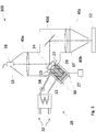
1 schematisch eine Bearbeitungsvorrichtung 100 zur Laserbearbeitung eines Werkstücks als ein erstes Beispiel gemäß Ausführungsformen der Erfindung; -
2 schematisch eine Bearbeitungsvorrichtung 200 zur Laserbearbeitung eines Werkstücks als ein zweites Beispiel gemäß Ausführungsformen der Erfindung; und -
3 schematisch eine Bearbeitungsvorrichtung 300 zur Laserbearbeitung eines Werkstücks als ein drittes Beispiel gemäß Ausführungsformen der Erfindung.
-
1 schematically aprocessing device 100 for laser machining a workpiece as a first example according to embodiments of the invention; -
2 schematically aprocessing device 200 for laser machining a workpiece as a second example according to embodiments of the invention; and -
3 schematically aprocessing device 300 for laser machining a workpiece as a third example according to embodiments of the invention.
BeispieleExamples
Im Folgenden wird die Bearbeitungsvorrichtung gemäß Ausführungsformen der Erfindung unter anderem anhand von Beispielen mit Bearbeitungskopf beschrieben, ohne die Erfindung darauf zu begrenzen. Die Bearbeitungsvorrichtung und das Verfahren gemäß Ausführungsformen der Erfindung können auch ohne Bearbeitungskopf realisiert sein/werden.In the following, the machining device according to embodiments of the invention is described, inter alia, by means of examples with a machining head, without limiting the invention thereto. The processing device and the method according to embodiments of the invention can also be implemented without a processing head.
Ferner gilt hier für die Beschreibung von Wertebereichen, dass die Angabe eines breiten Bereichs mit engeren alternativen oder bevorzugten Bereichen auch Bereiche offenbart, die durch eine beliebige Kombination angegebener unterer Bereichsgrenzen mit angegebenen oberen Bereichsgrenzen gebildet werden können.Furthermore, when describing value ranges, the specification of a broad range with narrower alternative or preferred ranges also reveals ranges that can be formed by any combination of specified lower range limits with specified upper range limits.
Der Begriff „zeitlich integriert“ oder „zeitlich gemittelt“ bedeutet vorliegend über einen Zeitraum oder eine Zeitperiode integriert oder gemittelt. Im Zusammenhang mit einer Fokalpunkt-Oszillation bedeutet dies über mindestens eine Oszillationsperiode integriert oder gemittelt, in Verbindung mit einem Strahlpendeln über mindestens eine Pendelperiode integriert oder gemittelt.The term “integrated over time” or “averaged over time” means integrated or averaged over a period or a time period. In connection with a focal point oscillation, this means integrated or averaged over at least one oscillation period, integrated or averaged over at least one oscillation period in connection with beam oscillation.
Die Begriffe „dynamische Bewegung“ des Laserstrahls oder „dynamisch bewegter“ Laserstrahl und Abwandlungen davon bedeuten vorliegend, dass der Laserstrahl hochfrequent, beispielsweise mit Frequenzen von 10 Hz bis 15 kHz, bewegt wird. Gleiches gilt analog für „dynamisch“ bewegbare, orientierbare und/oder verstellbare Elemente der Bearbeitungsvorrichtung.The terms “dynamic movement” of the laser beam or “dynamically moving” laser beam and modifications thereof mean here that the laser beam is moved at high frequencies, for example at frequencies of 10 Hz to 15 kHz. The same applies analogously to “dynamically” movable, orientable and / or adjustable elements of the processing device.
Die Bearbeitungsvorrichtung
Die Bearbeitungsvorrichtung
Die Bearbeitungsvorrichtung
Im vorliegenden Beispiel besitzt die Laserstrahlführungseinrichtung
Die reflektierende Oberfläche
In diesem Beispiel enthält die Laserstrahlführungseinrichtung
An der Laserstrahlführungseinrichtung
Die Wand
Im Betrieb wird ein Kühlfluid, z.B. Wasser, durch den Primärkreislauf
Für die Laserbearbeitung wird der Spiegel mit der beweglichen Oberfläche
Die Bearbeitungsvorrichtung
In einer Abwandlung (nicht gezeigt) des ersten Beispiels enthält die Laserstrahlführungseinrichtung
Der Sekundärkreislauf
In einer Abwandlung dieses Beispiels beinhaltet der Sekundärkreislauf
Im Betrieb wird das zweite Kühlfluid, vorliegend gasförmiges N2, durch den Sekundärkreislauf
Da der mindestens eine Aktuator
Durch die Kombination des Primärkreislaufs
In
Die Kühleinrichtung
Durch die zweistufige Kühleinrichtung
In einer Abwandlung des Beispiels der
Folgende Anwendungen der vorstehenden Abwandlung des dritten Beispiels mit Segmentspiegel sind möglich: Die Laserstrahlführungseinrichtung
In einer weiteren Abwandlung des dritten Beispiels weist die Laserstrahlführungseinrichtung
In Ausführungsformen der Bearbeitungsvorrichtung ist die mindestens eine bewegliche Oberfläche mittels mindestens eines gekühlten Aktuators dynamisch verstellbar. Ferner kann die mindestens eine bewegliche Oberfläche eine Oberflächeneinheit der Laserstrahlführungseinrichtung bereitstellen, deren Oberflächengeometrie, insbesondere deren Krümmung, dynamisch verstellbar ist. Dadurch kann nicht nur der Bearbeitungslaserstrahl zumindest senkrecht zu seiner Ausbreitungsrichtung geformt und/oder bewegt werden, sondern es kann auch die Divergenz des Bearbeitungslaserstrahls verändert und/oder die Fokuslage des Bearbeitungslaserstrahls parallel zu dessen Ausbreitungsrichtung verschoben werden.In embodiments of the processing device, the at least one movable surface can be adjusted dynamically by means of at least one cooled actuator. Furthermore, the at least one movable surface can provide a surface unit of the laser beam guiding device whose surface geometry, in particular its curvature, is dynamically adjustable. As a result, not only can the machining laser beam be shaped and / or moved at least perpendicular to its direction of propagation, but the divergence of the machining laser beam can also be changed and / or the focus position of the machining laser beam can be shifted parallel to its direction of propagation.
Die Ausführungsformen der Bearbeitungsvorrichtung ermöglichen mit der Laserstrahlführungseinrichtung und der dynamisch verstellbaren beweglichen Oberfläche eine Modifizierung des Strahlparameterprodukts des Bearbeitungslaserstrahls. Die Modifizierung des Strahlparameterprodukts kann mit statischer oder dynamischer Strahlformung des Bearbeitungslaserstrahls erfolgen, wodurch vorteilhafte Intensitätsverteilungen und Leistungsverteilungen seines Strahlspots bereitgestellt werden können.With the laser beam guiding device and the dynamically adjustable movable surface, the embodiments of the machining device enable the beam parameter product of the machining laser beam to be modified. The modification of the beam parameter product can take place with static or dynamic beam shaping of the processing laser beam, whereby advantageous intensity distributions and power distributions of its beam spot can be provided.
Durch die Kühlung des mindestens einen Aktuators werden die vorgenannten Funktionen der Laserstrahlführungseinrichtung auch bei hoher Wärmeeinwirkung/-entwicklung stabilisiert, insbesondere im Langzeitbetrieb bei zum Beispiel industriellen Anwendungen. Somit kann die mindestens eine bewegliche Oberfläche durch den mindestens einen gekühlten Aktuator in einem erwünschten Frequenzbereich und sogar bei hohen Frequenzen von mehreren 100 Hz bis einigen kHz zuverlässig verstellt werden, auch bei hoher Wärmeeinwirkung/-entwicklung und im Langzeitbetrieb.As a result of the cooling of the at least one actuator, the aforementioned functions of the laser beam guiding device are stabilized even in the event of high exposure to / development of heat, particularly in long-term operation in, for example, industrial applications. Thus, the at least one movable surface can be reliably adjusted by the at least one cooled actuator in a desired frequency range and even at high frequencies from several 100 Hz to several kHz, even with high heat exposure / development and in long-term operation.
Die Bearbeitungsvorrichtung gemäß Ausführungsformen ermöglicht ferner, dass der mindestens eine Aktuator gekühlt werden kann, ohne dass das erste Kühlfluid in Kontakt mit diesem kommt. Eine Verunreinigung des Aktuators und des Optikraums der Bearbeitungsvorrichtung mit dem ersten Kühlfluid wird so vermieden. Weitere Ausführungsformen ermöglichen, dass das zweite Kühlfluid, das mit dem Aktuator in Kontakt kommt und diesen kühlt, einen im Wesentlichen geschlossenen Kühlkreislauf durchströmt. Auf diese Weise werden Verschmutzungen und Beschädigungen von optischen Elementen im Optikraum minimiert.The processing device according to embodiments also enables the at least one actuator to be cooled without the first cooling fluid coming into contact therewith. A contamination of the actuator and the optics space of the processing device with the first cooling fluid is avoided. Further embodiments make it possible for the second cooling fluid, which comes into contact with the actuator and cools it, to flow through an essentially closed cooling circuit. In this way, soiling and damage to optical elements in the optics room are minimized.
Abschließend sei darauf hingewiesen, dass die Beschreibung der Erfindung und die Ausführungsbeispiele grundsätzlich nicht einschränkend in Hinblick auf eine bestimmte physikalische Realisierung der Erfindung zu verstehen sind. Alle in Verbindung mit einzelnen Ausführungsformen der Erfindung erläuterten und gezeigten Merkmale können in unterschiedlicher Kombination in dem erfindungsgemäßen Gegenstand vorgesehen sein, um gleichzeitig deren vorteilhafte Wirkungen zu realisieren.Finally, it should be pointed out that the description of the invention and the exemplary embodiments are in principle not to be understood as restrictive with regard to a specific physical implementation of the invention. All the features explained and shown in connection with individual embodiments of the invention can be provided in different combinations in the subject matter of the invention in order to simultaneously realize their advantageous effects.
Der Schutzbereich der vorliegenden Erfindung ist durch die Ansprüche gegeben und wird durch die in der Beschreibung erläuterten oder den Figuren gezeigten Merkmale nicht beschränkt.The scope of protection of the present invention is given by the claims and is not restricted by the features explained in the description or shown in the figures.
Für einen Fachmann ist es insbesondere offensichtlich, dass die Erfindung nicht nur für Laserbearbeitungsanlagen angewendet werden kann, sondern auch für andere Laser umfassende Geräte. Des Weiteren können die Bauteile der Bearbeitungsvorrichtung zur Laserbearbeitung von Werkstücken auf mehrere physikalische Produkte verteilt realisiert werden.It is particularly obvious to a person skilled in the art that the invention can be used not only for laser processing systems, but also for other devices comprising lasers. Furthermore, the components of the processing device for laser processing of workpieces can be implemented in a distributed manner over several physical products.
BezugszeichenlisteList of reference symbols
- 1212th
- Werkstückworkpiece
- 1313
- BearbeitungszoneProcessing zone
- 1414th
- erste Schnittstellefirst interface
- 1515th
- BearbeitungslaserstrahlMachining laser beam
- 1616
- BearbeitungslaserquelleMachining laser source
- 1717th
- zweite Schnittstellesecond interface
- 1818th
- AustrittsöffnungOutlet opening
- 2222nd
- LaserstrahlführungseinrichtungLaser beam guiding device
- 2323
- Öffnungopening
- 2424
- bewegliche Oberflächemovable surface
- 2626th
- AktuatorActuator
- 2727
- SteuerungseinheitControl unit
- 2828
- KühleinrichtungCooling device
- 3030th
- PrimärkreislaufPrimary circuit
- 3232
- PrimärkreislaufPrimary circuit
- 3434
- SekundärkreislaufSecondary circuit
- 3535
- UmwälzpumpeCirculation pump
- 3636
- Innenrauminner space
- 3737
- Kühlstruktur, WandCooling structure, wall
- 40a40a
- Linselens
- 40b40b
- Linselens
- 40d40d
- UmlenkspiegelDeflection mirror
- 40c40c
- SchutzglasProtective glass
- 100100
- BearbeitungsvorrichtungMachining device
- 200200
- BearbeitungsvorrichtungMachining device
- 300300
- BearbeitungsvorrichtungMachining device
ZITATE ENTHALTEN IN DER BESCHREIBUNGQUOTES INCLUDED IN THE DESCRIPTION
Diese Liste der vom Anmelder aufgeführten Dokumente wurde automatisiert erzeugt und ist ausschließlich zur besseren Information des Lesers aufgenommen. Die Liste ist nicht Bestandteil der deutschen Patent- bzw. Gebrauchsmusteranmeldung. Das DPMA übernimmt keinerlei Haftung für etwaige Fehler oder Auslassungen.This list of the documents listed by the applicant was generated automatically and is included solely for the better information of the reader. The list is not part of the German patent or utility model application. The DPMA assumes no liability for any errors or omissions.
Zitierte PatentliteraturPatent literature cited
- EP 3412400 A1 [0005]EP 3412400 A1 [0005]
- US 8781269 B2 [0005]US 8781269 B2 [0005]
- US 9250390 B2 [0005]US 9250390 B2 [0005]
- US 9346126 B2 [0005]US 9346126 B2 [0005]
- EP 2730363 A1 [0005]EP 2730363 A1 [0005]
- EP 2762263 A1 [0005]EP 2762263 A1 [0005]
- DE 2821883 B1 [0005]DE 2821883 B1 [0005]
- DE 102015116033 A1 [0005]DE 102015116033 A1 [0005]
- EP 2778746 B1 [0005]EP 2778746 B1 [0005]
- DE 102015101263 A1 [0005]DE 102015101263 A1 [0005]
- DE 102008053397 B4 [0005]DE 102008053397 B4 [0005]
- US 5777807 A [0010]US 5777807 A [0010]
- US 2001008469 A [0010]US 2001008469 A [0010]
- EP 1104940 A1 [0010]EP 1104940 A1 [0010]
Claims (17)
Priority Applications (6)
| Application Number | Priority Date | Filing Date | Title |
|---|---|---|---|
| DE102019122064.5A DE102019122064A1 (en) | 2019-08-16 | 2019-08-16 | Processing device for laser processing of a workpiece, parts set for a processing device for laser processing of a workpiece and method for laser processing of a workpiece |
| EP20757576.2A EP3921109B1 (en) | 2019-08-16 | 2020-08-14 | Machining apparatus for laser machining a workpiece, set of parts for a machining apparatus for laser machining a workpiece and method for laser machining a workpiece using such machining apparatus |
| CN202080028030.7A CN113677476B (en) | 2019-08-16 | 2020-08-14 | Machining device for laser machining workpieces, kit of parts for a machining device for laser machining workpieces, and method for laser machining workpieces using such a machining device |
| US17/310,982 US11471979B2 (en) | 2019-08-16 | 2020-08-14 | Machining apparatus for laser machining a workpiece, set of parts for a machining apparatus for laser machining a workpiece and method for laser machining a workpiece using such machining apparatus |
| PCT/EP2020/072878 WO2021032625A1 (en) | 2019-08-16 | 2020-08-14 | Machining apparatus for laser machining a workpiece, set of parts for a machining apparatus for laser machining a workpiece and method for laser machining a workpiece using such machining apparatus |
| JP2021560109A JP7217363B2 (en) | 2019-08-16 | 2020-08-14 | Machining Apparatus for Laser Machining a Workpiece, Parts Set for Machining Apparatus for Laser Machining Workpiece, and Method for Laser Machining Workpiece Using Such Machining Apparatus |
Applications Claiming Priority (1)
| Application Number | Priority Date | Filing Date | Title |
|---|---|---|---|
| DE102019122064.5A DE102019122064A1 (en) | 2019-08-16 | 2019-08-16 | Processing device for laser processing of a workpiece, parts set for a processing device for laser processing of a workpiece and method for laser processing of a workpiece |
Publications (1)
| Publication Number | Publication Date |
|---|---|
| DE102019122064A1 true DE102019122064A1 (en) | 2021-02-18 |
Family
ID=72139600
Family Applications (1)
| Application Number | Title | Priority Date | Filing Date |
|---|---|---|---|
| DE102019122064.5A Ceased DE102019122064A1 (en) | 2019-08-16 | 2019-08-16 | Processing device for laser processing of a workpiece, parts set for a processing device for laser processing of a workpiece and method for laser processing of a workpiece |
Country Status (6)
| Country | Link |
|---|---|
| US (1) | US11471979B2 (en) |
| EP (1) | EP3921109B1 (en) |
| JP (1) | JP7217363B2 (en) |
| CN (1) | CN113677476B (en) |
| DE (1) | DE102019122064A1 (en) |
| WO (1) | WO2021032625A1 (en) |
Cited By (6)
| Publication number | Priority date | Publication date | Assignee | Title |
|---|---|---|---|---|
| CN113798710A (en) * | 2021-10-20 | 2021-12-17 | 中国工程物理研究院激光聚变研究中心 | An opening and closing joint structure of a laser light guide arm |
| DE102022002164A1 (en) | 2022-06-15 | 2023-12-21 | Fritz Stepper GmbH & Co. KG. | Laser welding head |
| DE102022116491A1 (en) * | 2022-07-01 | 2024-01-04 | Precitec Gmbh & Co. Kg | LASER PROCESSING HEAD WITH OVERHEATING PROTECTION DEVICE |
| DE102022116486A1 (en) * | 2022-07-01 | 2024-01-04 | Precitec Gmbh & Co. Kg | LASER PROCESSING HEAD WITH A TWO-PHASE CLOSED HEAT EXCHANGER |
| DE102022002959A1 (en) * | 2022-08-15 | 2024-02-15 | Fritz Stepper GmbH & Co. KG. | Welding device and method for welding two workpieces |
| EP4494801A1 (en) | 2023-07-19 | 2025-01-22 | Bystronic Laser AG | Control of an optical system of a laser cutting machine for compensating thermal drift |
Families Citing this family (3)
| Publication number | Priority date | Publication date | Assignee | Title |
|---|---|---|---|---|
| EP3747588A1 (en) * | 2019-06-07 | 2020-12-09 | Bystronic Laser AG | Processing device for laser processing of a workpiece and method for laser processing of a workpiece |
| EP4431222B1 (en) * | 2023-03-14 | 2025-05-14 | Raylase GmbH | Predictive cooling for a laser processing device |
| JP7573701B1 (en) | 2023-08-10 | 2024-10-25 | 株式会社アマダ | Galvanometer mirror and laser processing machine |
Citations (15)
| Publication number | Priority date | Publication date | Assignee | Title |
|---|---|---|---|---|
| DE2821883B1 (en) * | 1978-05-19 | 1979-10-31 | Ibm Deutschland | Device for material processing |
| DE9409869U1 (en) * | 1994-06-17 | 1995-10-12 | Diehl GmbH & Co, 90478 Nürnberg | Deformable mirror, in particular for a laser beam material processing device |
| EP1030206A2 (en) * | 1999-02-17 | 2000-08-23 | Sumitomo Electric Industries, Ltd. | Deformable mirror for laser beam |
| EP1104940A1 (en) * | 1999-12-02 | 2001-06-06 | Piezomechanik GmbH | Solid state actuator, in particular piezoelectric actuator |
| US20010008469A1 (en) * | 2000-01-19 | 2001-07-19 | Klaus Bar | Deformable mirror, in particular for a laser beam material machining apparatus |
| DE102008053397B4 (en) * | 2008-05-20 | 2012-12-27 | Fraunhofer-Gesellschaft zur Förderung der angewandten Forschung e.V. | Method for the fusion cutting of workpieces with laser radiation |
| EP2730363A1 (en) * | 2012-11-12 | 2014-05-14 | Mitsubishi Heavy Industries, Ltd. | Optical system and laser processing apparatus |
| US8781269B2 (en) * | 2010-04-08 | 2014-07-15 | Trumpf Laser- Und Systemtechnik Gmbh | Method and arrangement for generating a laser beam having a differing beam profile characteristic by means of a multi-clad fiber |
| EP2762263A1 (en) * | 2011-09-16 | 2014-08-06 | Amada Company, Limited | Method and device for laser cutting process |
| EP2778746B1 (en) * | 2013-03-12 | 2016-01-13 | Highyag Lasertechnologie GmbH | Optical device for beam formation |
| US9250390B2 (en) * | 2011-12-09 | 2016-02-02 | Lumentum Operations Llc | Varying beam parameter product of a laser beam |
| DE102015116033A1 (en) * | 2014-09-30 | 2016-03-31 | Fanuc Corporation | Laser processing device capable of enlarging the diameter of the focused beam |
| US9346126B2 (en) * | 2011-05-30 | 2016-05-24 | Mitsubishi Heavy Industries, Ltd. | Laser processing head, laser processing apparatus, optical system of laser processing apparatus, laser processing method, and laser focusing method |
| DE102015101263A1 (en) * | 2015-01-28 | 2016-07-28 | Precitec Gmbh & Co. Kg | Device for processing materials by means of laser radiation |
| EP3412400A1 (en) * | 2017-06-09 | 2018-12-12 | Bystronic Laser AG | Beam shaper and use thereof, device for laser beam treatment of a workpiece and use thereof, method for laser beam treatment of a workpiece |
Family Cites Families (32)
| Publication number | Priority date | Publication date | Assignee | Title |
|---|---|---|---|---|
| US4048464A (en) * | 1975-08-22 | 1977-09-13 | Fuji Photo Film Co., Ltd. | Method of and means for cutting hose for high pressure hydraulic systems |
| JPS55100523A (en) * | 1979-01-29 | 1980-07-31 | Nec Corp | Laser working optical device |
| US4202605A (en) * | 1979-04-05 | 1980-05-13 | Rockwell International Corporation | Active segmented mirror |
| JPS60102290A (en) * | 1983-11-09 | 1985-06-06 | Hitachi Ltd | Laser working device |
| IT1196856B (en) * | 1986-12-19 | 1988-11-25 | Fiat Auto Spa | PROCESSING PROCESS OF LARGE CAST IRON MOLDS PARTICULARLY FOR THE MOLDING OF VEHICLE SHEETS AND EQUIPMENT FOR ITS REALIZATION |
| JPH01228691A (en) * | 1988-03-08 | 1989-09-12 | Mitsubishi Electric Corp | Bending mirror for laser bean machine |
| JPH05106957A (en) * | 1991-10-14 | 1993-04-27 | Orion Mach Co Ltd | Cooling device in laser machining machine |
| IL100664A0 (en) * | 1992-01-15 | 1992-09-06 | Laser Ind Ltd | Method and apparatus for controlling a laser beam |
| DE4206792A1 (en) * | 1992-03-04 | 1993-09-09 | Diehl Gmbh & Co | Deformable mirror e.g. for focussing laser beam - has fixing collar of shape-memory alloy, attached by radial forces at one temp. and released at other temp. |
| JP2829192B2 (en) * | 1992-05-15 | 1998-11-25 | 住友電気工業株式会社 | Laser beam scanner |
| JP3060813B2 (en) * | 1993-12-28 | 2000-07-10 | トヨタ自動車株式会社 | Laser processing equipment |
| JPH07261100A (en) * | 1994-03-17 | 1995-10-13 | Hitachi Ltd | Deformable mirror |
| JP3178294B2 (en) * | 1995-03-28 | 2001-06-18 | 三菱電機株式会社 | Laser processing machine |
| JPH10235485A (en) * | 1997-02-26 | 1998-09-08 | Amada Co Ltd | Cooling method for optical parts in laser beam machine and its device |
| JP2000334592A (en) * | 1999-05-25 | 2000-12-05 | Mitsubishi Electric Corp | Optical reflector and cooling method of optical reflector |
| US6605796B2 (en) * | 2000-05-25 | 2003-08-12 | Westar Photonics | Laser beam shaping device and apparatus for material machining |
| DE10052250A1 (en) * | 2000-10-21 | 2002-04-25 | Lt Ultra Prec Technology Gmbh | Adaptive mirror for use as a laser beam guidance component includes a casing assigned with an oval, elliptical mirror element able to be reshaped. |
| EP1447068A1 (en) * | 2003-02-14 | 2004-08-18 | Fameccanica.Data S.p.A. | Process and device for the localised treatment of articles, for example hygienic and sanitary products |
| US6706999B1 (en) * | 2003-02-24 | 2004-03-16 | Electro Scientific Industries, Inc. | Laser beam tertiary positioner apparatus and method |
| EP2238345B1 (en) * | 2007-12-21 | 2011-06-01 | Vestas Wind Systems A/S | A wind turbine generator with a heat exchanger |
| DE102008022014B3 (en) * | 2008-05-02 | 2009-11-26 | Trumpf Laser- Und Systemtechnik Gmbh | Dynamic beam deflection of a laser beam |
| JP5452784B1 (en) * | 2012-09-05 | 2014-03-26 | 三菱電機株式会社 | Laser processing equipment |
| DE112013007410B4 (en) * | 2013-10-15 | 2020-01-30 | Trumpf Laser- Und Systemtechnik Gmbh | Cooling system for an optical element of a laser system and arrangement of a laser system with a cooling system |
| US9366887B2 (en) * | 2014-02-26 | 2016-06-14 | TeraDiode, Inc. | Systems and methods for laser systems with variable beam parameter product utilizing thermo-optic effects |
| ES2887211T3 (en) * | 2015-06-19 | 2021-12-22 | Ipg Photonics Corp | Laser welding system with a laser welding head equipped with dual moving mirrors that provide limited field of view beam movement |
| IT201600070352A1 (en) * | 2016-07-06 | 2018-01-06 | Adige Spa | Process for laser processing of a metal material with control of the transverse power distribution of the laser beam in a working plane, as well as a machine and computer program for carrying out such a process. |
| CN106363299A (en) * | 2016-11-11 | 2017-02-01 | 西安必盛激光科技有限公司 | Ultrahigh-power laser depleting equipment and depleting method thereof |
| US10508803B2 (en) * | 2018-02-06 | 2019-12-17 | Xerox Corporation | Synthetic jets to cool digital micromirror devices |
| CN208255526U (en) * | 2018-05-18 | 2018-12-18 | 宁波大学 | A kind of piezoelectric deforming mirror with compound actuating water cooling function |
| CN108857098A (en) * | 2018-09-06 | 2018-11-23 | 南京艾峰科技有限公司 | A kind of Intelligent Laser sanction head having refrigerating function |
| CN109158764B (en) * | 2018-09-10 | 2020-06-05 | 安徽鹏展电子科技有限公司 | Special novel high efficiency cooling device of laser head |
| EP3747588A1 (en) * | 2019-06-07 | 2020-12-09 | Bystronic Laser AG | Processing device for laser processing of a workpiece and method for laser processing of a workpiece |
-
2019
- 2019-08-16 DE DE102019122064.5A patent/DE102019122064A1/en not_active Ceased
-
2020
- 2020-08-14 EP EP20757576.2A patent/EP3921109B1/en active Active
- 2020-08-14 CN CN202080028030.7A patent/CN113677476B/en active Active
- 2020-08-14 JP JP2021560109A patent/JP7217363B2/en active Active
- 2020-08-14 WO PCT/EP2020/072878 patent/WO2021032625A1/en not_active Ceased
- 2020-08-14 US US17/310,982 patent/US11471979B2/en active Active
Patent Citations (16)
| Publication number | Priority date | Publication date | Assignee | Title |
|---|---|---|---|---|
| DE2821883B1 (en) * | 1978-05-19 | 1979-10-31 | Ibm Deutschland | Device for material processing |
| DE9409869U1 (en) * | 1994-06-17 | 1995-10-12 | Diehl GmbH & Co, 90478 Nürnberg | Deformable mirror, in particular for a laser beam material processing device |
| US5777807A (en) * | 1994-06-17 | 1998-07-07 | Diehl Gmbh & Co. | Deformable mirror, in particular for a laser beam material machining apparatus |
| EP1030206A2 (en) * | 1999-02-17 | 2000-08-23 | Sumitomo Electric Industries, Ltd. | Deformable mirror for laser beam |
| EP1104940A1 (en) * | 1999-12-02 | 2001-06-06 | Piezomechanik GmbH | Solid state actuator, in particular piezoelectric actuator |
| US20010008469A1 (en) * | 2000-01-19 | 2001-07-19 | Klaus Bar | Deformable mirror, in particular for a laser beam material machining apparatus |
| DE102008053397B4 (en) * | 2008-05-20 | 2012-12-27 | Fraunhofer-Gesellschaft zur Förderung der angewandten Forschung e.V. | Method for the fusion cutting of workpieces with laser radiation |
| US8781269B2 (en) * | 2010-04-08 | 2014-07-15 | Trumpf Laser- Und Systemtechnik Gmbh | Method and arrangement for generating a laser beam having a differing beam profile characteristic by means of a multi-clad fiber |
| US9346126B2 (en) * | 2011-05-30 | 2016-05-24 | Mitsubishi Heavy Industries, Ltd. | Laser processing head, laser processing apparatus, optical system of laser processing apparatus, laser processing method, and laser focusing method |
| EP2762263A1 (en) * | 2011-09-16 | 2014-08-06 | Amada Company, Limited | Method and device for laser cutting process |
| US9250390B2 (en) * | 2011-12-09 | 2016-02-02 | Lumentum Operations Llc | Varying beam parameter product of a laser beam |
| EP2730363A1 (en) * | 2012-11-12 | 2014-05-14 | Mitsubishi Heavy Industries, Ltd. | Optical system and laser processing apparatus |
| EP2778746B1 (en) * | 2013-03-12 | 2016-01-13 | Highyag Lasertechnologie GmbH | Optical device for beam formation |
| DE102015116033A1 (en) * | 2014-09-30 | 2016-03-31 | Fanuc Corporation | Laser processing device capable of enlarging the diameter of the focused beam |
| DE102015101263A1 (en) * | 2015-01-28 | 2016-07-28 | Precitec Gmbh & Co. Kg | Device for processing materials by means of laser radiation |
| EP3412400A1 (en) * | 2017-06-09 | 2018-12-12 | Bystronic Laser AG | Beam shaper and use thereof, device for laser beam treatment of a workpiece and use thereof, method for laser beam treatment of a workpiece |
Non-Patent Citations (5)
| Title |
|---|
| FRAUNHOFER-INSTITUT FÜR ANGEWANDTE OPTIK UND FEINMECHANIK IOF: Messe-Highlights 2019: Das Fraunhofer IOF auf der LASER World of PHOTONICS. 03-06-2019. S. 1-4. URL: https://www.iof.fraunhofer.de/content/dam/iof/de/documents/Presse/2019/PM-Messehighligts-LASER_World_of_PHOTONICS-2019-Fraunhofer_IOF.pdf [abgerufen am 2019-10-17] * |
| FRAUNHOFER-INSTITUT FÜR WERKSTOFF-UND STRAHLTECHNIK IWS DRESDEN: Dynamic beam shaping increases the attractiveness of laser beam fusion cutting. 21-10-2016. 2 S. URL: https://www.iws.fraunhofer.de/content/dam/iws/en/documents/press/2016/p16_15_euroBLECH_en.pdf [abgerufen am 2019-10-17] * |
| PHYSIK INSTRUMENTE (PI) GmbH & Co. KG: P-21x Piezoaktor Benutzerhandbuch - Version 1.1.0. Karlsruhe, 2018 (PZ249D). 59 S. - Firmenschrift. URL: https://static.physikinstrumente.com/fileadmin/user_upload/physik_instrumente/files/user_manuals/P-21x-Benutzerhandbuch-PZ249D110.pdf [abgerufen am 2019-10-17] * |
| PHYSIK INSTRUMENTE (PI) GmbH & Co. KG: Piezoelektrische Aktoren. Karlsruhe, 2012 (CAT128D). S. 1-70. - Firmenschrift. URL: https://www.physikinstrumente.de/fileadmin/user_upload/pi_ceramic/files/catalog_CAT/PI_Piezoelektrische_Aktoren_CAT128D.pdf [abgerufen am 2019-10-17] * |
| PIEZOMECHNIK DR. LUTZ PICKELMANN GmbH: Einstieg in die Piezoaktorik. München, 2010. S. 1-75. - Firmenschrift. URL: https://www.piezomechanik.com/fileadmin/filestorage/Kataloge/de/Piezomechanik_Katalog_D_2010-05-05_web.pdf [abgerufen am 2019-10-17] * |
Cited By (9)
| Publication number | Priority date | Publication date | Assignee | Title |
|---|---|---|---|---|
| CN113798710A (en) * | 2021-10-20 | 2021-12-17 | 中国工程物理研究院激光聚变研究中心 | An opening and closing joint structure of a laser light guide arm |
| CN113798710B (en) * | 2021-10-20 | 2024-01-12 | 中国工程物理研究院激光聚变研究中心 | A kind of opening and closing joint structure of laser light guide arm |
| DE102022002164A1 (en) | 2022-06-15 | 2023-12-21 | Fritz Stepper GmbH & Co. KG. | Laser welding head |
| DE102022116491A1 (en) * | 2022-07-01 | 2024-01-04 | Precitec Gmbh & Co. Kg | LASER PROCESSING HEAD WITH OVERHEATING PROTECTION DEVICE |
| DE102022116486A1 (en) * | 2022-07-01 | 2024-01-04 | Precitec Gmbh & Co. Kg | LASER PROCESSING HEAD WITH A TWO-PHASE CLOSED HEAT EXCHANGER |
| DE102022116491B4 (en) * | 2022-07-01 | 2025-11-27 | Precitec Gmbh & Co. Kg | LASER PROCESSING HEAD WITH OVERHEATING PROTECTION DEVICE |
| DE102022002959A1 (en) * | 2022-08-15 | 2024-02-15 | Fritz Stepper GmbH & Co. KG. | Welding device and method for welding two workpieces |
| EP4494801A1 (en) | 2023-07-19 | 2025-01-22 | Bystronic Laser AG | Control of an optical system of a laser cutting machine for compensating thermal drift |
| WO2025017079A1 (en) | 2023-07-19 | 2025-01-23 | Bystronic Laser Ag | Closed-loop control of an optical system of a laser cutting machine in order to compensate for thermal drift |
Also Published As
| Publication number | Publication date |
|---|---|
| CN113677476B (en) | 2023-04-18 |
| JP2022526435A (en) | 2022-05-24 |
| WO2021032625A1 (en) | 2021-02-25 |
| EP3921109B1 (en) | 2022-11-23 |
| CN113677476A (en) | 2021-11-19 |
| US20220040795A1 (en) | 2022-02-10 |
| JP7217363B2 (en) | 2023-02-02 |
| US11471979B2 (en) | 2022-10-18 |
| EP3921109A1 (en) | 2021-12-15 |
Similar Documents
| Publication | Publication Date | Title |
|---|---|---|
| DE102019122064A1 (en) | Processing device for laser processing of a workpiece, parts set for a processing device for laser processing of a workpiece and method for laser processing of a workpiece | |
| DE112012004608B4 (en) | Optical setup for line generation using a microlens array | |
| DE19520187C1 (en) | Optical system for excimer laser | |
| DE102011117607B4 (en) | Optical system and use of the optical system | |
| DE19780124B4 (en) | Arrangement for forming the geometric cross section of a plurality of solid-state and / or semiconductor lasers | |
| DE102019115554A1 (en) | Processing device for laser processing of a workpiece and method for laser processing of a workpiece | |
| DE102008022014B3 (en) | Dynamic beam deflection of a laser beam | |
| DE102013210052B4 (en) | Laser processing device | |
| DE102019125103A1 (en) | Processing device for laser processing of a workpiece, method for laser processing of a workpiece | |
| WO2017001220A1 (en) | Laser-machining head and laser-machining machine comprising same | |
| EP3747588A1 (en) | Processing device for laser processing of a workpiece and method for laser processing of a workpiece | |
| DE102018208752B4 (en) | Device and method for machining workpieces that are difficult to access and use of a device | |
| DE102016211811A1 (en) | F-theta lens and scanner device with it | |
| DE102015212284A1 (en) | Apparatus and method for powder-based laser deposition welding | |
| DE102018106579A1 (en) | Method for processing a workpiece by means of irradiation with laser radiation and device therefor | |
| DE102015200795B3 (en) | Arrangement for irradiating an object surface with a plurality of partial beams of ultrashort pulsed laser radiation | |
| DE102016225701A1 (en) | Method for operating an EUV lithography system | |
| DE10233491A1 (en) | Compact device for imaging a printing form | |
| DE102020121440B4 (en) | Device for generating a defined laser line on a working plane | |
| EP3042551B1 (en) | Beam guiding apparatus and euv radiation generating equipment incorporating same | |
| WO2008061516A1 (en) | Method and device for adjusting the beam diameter of a laser beam passing through an optical element by means of temperature changes | |
| DE102025107882B3 (en) | Laser projection device and method for projecting laser radiation | |
| EP4477347A1 (en) | Laser machining device and laser machining method for processing a workpiece | |
| DE102011006152A1 (en) | Laser trepanning device for setting and varying propagation angle and lateral displacement of laser beam, has control device that is provided to control two orthogonal tilting axes of two tilting mirrors | |
| EP3815835B1 (en) | Laser machining head and method for laser machining a workpiece |
Legal Events
| Date | Code | Title | Description |
|---|---|---|---|
| R012 | Request for examination validly filed | ||
| R082 | Change of representative |
Representative=s name: PATENTANWAELTE GEYER, FEHNERS & PARTNER MBB, DE |
|
| R082 | Change of representative |
Representative=s name: PATENTANWAELTE GEYER, FEHNERS & PARTNER MBB, DE |
|
| R016 | Response to examination communication | ||
| R002 | Refusal decision in examination/registration proceedings | ||
| R003 | Refusal decision now final |