DE102019103248A1 - Laser processing head with the function of rectifying auxiliary gas - Google Patents

Laser processing head with the function of rectifying auxiliary gas Download PDF

Info

Publication number
DE102019103248A1
DE102019103248A1 DE102019103248.2A DE102019103248A DE102019103248A1 DE 102019103248 A1 DE102019103248 A1 DE 102019103248A1 DE 102019103248 A DE102019103248 A DE 102019103248A DE 102019103248 A1 DE102019103248 A1 DE 102019103248A1
Authority
DE
Germany
Prior art keywords
laser processing
processing head
stream
group
flow
Prior art date
Legal status (The legal status is an assumption and is not a legal conclusion. Google has not performed a legal analysis and makes no representation as to the accuracy of the status listed.)
Withdrawn
Application number
DE102019103248.2A
Other languages
German (de)
Inventor
Takashi Izumi
Current Assignee (The listed assignees may be inaccurate. Google has not performed a legal analysis and makes no representation or warranty as to the accuracy of the list.)
Fanuc Corp
Original Assignee
Fanuc Corp
Priority date (The priority date is an assumption and is not a legal conclusion. Google has not performed a legal analysis and makes no representation as to the accuracy of the date listed.)
Filing date
Publication date
Application filed by Fanuc Corp filed Critical Fanuc Corp
Publication of DE102019103248A1 publication Critical patent/DE102019103248A1/en
Withdrawn legal-status Critical Current

Links

Images

Classifications

    • BPERFORMING OPERATIONS; TRANSPORTING
    • B23MACHINE TOOLS; METAL-WORKING NOT OTHERWISE PROVIDED FOR
    • B23KSOLDERING OR UNSOLDERING; WELDING; CLADDING OR PLATING BY SOLDERING OR WELDING; CUTTING BY APPLYING HEAT LOCALLY, e.g. FLAME CUTTING; WORKING BY LASER BEAM
    • B23K26/00Working by laser beam, e.g. welding, cutting or boring
    • B23K26/02Positioning or observing the workpiece, e.g. with respect to the point of impact; Aligning, aiming or focusing the laser beam
    • B23K26/04Automatically aligning, aiming or focusing the laser beam, e.g. using the back-scattered light
    • BPERFORMING OPERATIONS; TRANSPORTING
    • B23MACHINE TOOLS; METAL-WORKING NOT OTHERWISE PROVIDED FOR
    • B23KSOLDERING OR UNSOLDERING; WELDING; CLADDING OR PLATING BY SOLDERING OR WELDING; CUTTING BY APPLYING HEAT LOCALLY, e.g. FLAME CUTTING; WORKING BY LASER BEAM
    • B23K26/00Working by laser beam, e.g. welding, cutting or boring
    • B23K26/02Positioning or observing the workpiece, e.g. with respect to the point of impact; Aligning, aiming or focusing the laser beam
    • B23K26/06Shaping the laser beam, e.g. by masks or multi-focusing
    • BPERFORMING OPERATIONS; TRANSPORTING
    • B23MACHINE TOOLS; METAL-WORKING NOT OTHERWISE PROVIDED FOR
    • B23KSOLDERING OR UNSOLDERING; WELDING; CLADDING OR PLATING BY SOLDERING OR WELDING; CUTTING BY APPLYING HEAT LOCALLY, e.g. FLAME CUTTING; WORKING BY LASER BEAM
    • B23K26/00Working by laser beam, e.g. welding, cutting or boring
    • B23K26/02Positioning or observing the workpiece, e.g. with respect to the point of impact; Aligning, aiming or focusing the laser beam
    • B23K26/06Shaping the laser beam, e.g. by masks or multi-focusing
    • B23K26/064Shaping the laser beam, e.g. by masks or multi-focusing by means of optical elements, e.g. lenses, mirrors or prisms
    • B23K26/0648Shaping the laser beam, e.g. by masks or multi-focusing by means of optical elements, e.g. lenses, mirrors or prisms comprising lenses
    • BPERFORMING OPERATIONS; TRANSPORTING
    • B23MACHINE TOOLS; METAL-WORKING NOT OTHERWISE PROVIDED FOR
    • B23KSOLDERING OR UNSOLDERING; WELDING; CLADDING OR PLATING BY SOLDERING OR WELDING; CUTTING BY APPLYING HEAT LOCALLY, e.g. FLAME CUTTING; WORKING BY LASER BEAM
    • B23K26/00Working by laser beam, e.g. welding, cutting or boring
    • B23K26/14Working by laser beam, e.g. welding, cutting or boring using a fluid stream, e.g. a jet of gas, in conjunction with the laser beam; Nozzles therefor
    • BPERFORMING OPERATIONS; TRANSPORTING
    • B23MACHINE TOOLS; METAL-WORKING NOT OTHERWISE PROVIDED FOR
    • B23KSOLDERING OR UNSOLDERING; WELDING; CLADDING OR PLATING BY SOLDERING OR WELDING; CUTTING BY APPLYING HEAT LOCALLY, e.g. FLAME CUTTING; WORKING BY LASER BEAM
    • B23K26/00Working by laser beam, e.g. welding, cutting or boring
    • B23K26/14Working by laser beam, e.g. welding, cutting or boring using a fluid stream, e.g. a jet of gas, in conjunction with the laser beam; Nozzles therefor
    • B23K26/1435Working by laser beam, e.g. welding, cutting or boring using a fluid stream, e.g. a jet of gas, in conjunction with the laser beam; Nozzles therefor involving specially adapted flow-control means
    • B23K26/1437Working by laser beam, e.g. welding, cutting or boring using a fluid stream, e.g. a jet of gas, in conjunction with the laser beam; Nozzles therefor involving specially adapted flow-control means for flow-rate control
    • BPERFORMING OPERATIONS; TRANSPORTING
    • B23MACHINE TOOLS; METAL-WORKING NOT OTHERWISE PROVIDED FOR
    • B23KSOLDERING OR UNSOLDERING; WELDING; CLADDING OR PLATING BY SOLDERING OR WELDING; CUTTING BY APPLYING HEAT LOCALLY, e.g. FLAME CUTTING; WORKING BY LASER BEAM
    • B23K26/00Working by laser beam, e.g. welding, cutting or boring
    • B23K26/14Working by laser beam, e.g. welding, cutting or boring using a fluid stream, e.g. a jet of gas, in conjunction with the laser beam; Nozzles therefor
    • B23K26/1435Working by laser beam, e.g. welding, cutting or boring using a fluid stream, e.g. a jet of gas, in conjunction with the laser beam; Nozzles therefor involving specially adapted flow-control means
    • B23K26/1438Working by laser beam, e.g. welding, cutting or boring using a fluid stream, e.g. a jet of gas, in conjunction with the laser beam; Nozzles therefor involving specially adapted flow-control means for directional control
    • BPERFORMING OPERATIONS; TRANSPORTING
    • B23MACHINE TOOLS; METAL-WORKING NOT OTHERWISE PROVIDED FOR
    • B23KSOLDERING OR UNSOLDERING; WELDING; CLADDING OR PLATING BY SOLDERING OR WELDING; CUTTING BY APPLYING HEAT LOCALLY, e.g. FLAME CUTTING; WORKING BY LASER BEAM
    • B23K26/00Working by laser beam, e.g. welding, cutting or boring
    • B23K26/14Working by laser beam, e.g. welding, cutting or boring using a fluid stream, e.g. a jet of gas, in conjunction with the laser beam; Nozzles therefor
    • B23K26/1462Nozzles; Features related to nozzles
    • B23K26/1464Supply to, or discharge from, nozzles of media, e.g. gas, powder, wire
    • B23K26/1476Features inside the nozzle for feeding the fluid stream through the nozzle
    • BPERFORMING OPERATIONS; TRANSPORTING
    • B23MACHINE TOOLS; METAL-WORKING NOT OTHERWISE PROVIDED FOR
    • B23KSOLDERING OR UNSOLDERING; WELDING; CLADDING OR PLATING BY SOLDERING OR WELDING; CUTTING BY APPLYING HEAT LOCALLY, e.g. FLAME CUTTING; WORKING BY LASER BEAM
    • B23K26/00Working by laser beam, e.g. welding, cutting or boring
    • B23K26/70Auxiliary operations or equipment
    • B23K26/702Auxiliary equipment
    • BPERFORMING OPERATIONS; TRANSPORTING
    • B23MACHINE TOOLS; METAL-WORKING NOT OTHERWISE PROVIDED FOR
    • B23KSOLDERING OR UNSOLDERING; WELDING; CLADDING OR PLATING BY SOLDERING OR WELDING; CUTTING BY APPLYING HEAT LOCALLY, e.g. FLAME CUTTING; WORKING BY LASER BEAM
    • B23K26/00Working by laser beam, e.g. welding, cutting or boring
    • B23K26/70Auxiliary operations or equipment
    • B23K26/702Auxiliary equipment
    • B23K26/706Protective screens

Landscapes

  • Physics & Mathematics (AREA)
  • Optics & Photonics (AREA)
  • Engineering & Computer Science (AREA)
  • Plasma & Fusion (AREA)
  • Mechanical Engineering (AREA)
  • Fluid Mechanics (AREA)
  • Laser Beam Processing (AREA)

Abstract

Ein Laserbearbeitungskopf weist die Funktion des Gleichrichtens von Hilfsgas auf und umfasst ein Schutzfenster; eine Düse, die ein Hilfsgas zu einem zu bearbeitenden Material bläst; eine Kammer, die den Raum zwischen dem Schutzfenster und der Düse definiert; eine Einströmöffnung, die in der Kammer angeordnet ist und das Hilfsgas einbringt; und einen Stromteilungsvorsprung, der an einer der Einströmöffnung gegenüberliegenden Position angeordnet ist und das Hilfsgas von der Einströmöffnung in einen ersten Strom und einen zweiten Strom, die entlang der Umfangsrichtung einer optischen Achse des Laserlichts fließen, teilt.

Figure DE102019103248A1_0000
A laser processing head has the function of rectifying auxiliary gas and includes a protective window; a nozzle that blows an auxiliary gas to a material to be processed; a chamber defining the space between the protective window and the nozzle; an inflow port disposed in the chamber and introducing the assist gas; and a flow splitting protrusion disposed at a position opposite to the inflow port and dividing the assist gas from the inflow port into a first flow and a second flow flowing along the circumferential direction of an optical axis of the laser light.
Figure DE102019103248A1_0000

Description

Allgemeiner Stand der TechnikGeneral state of the art

Gebiet der ErfindungField of the invention

Die vorliegende Erfindung betrifft einen Laserbearbeitungskopf, und betrifft insbesondere einen Laserbearbeitungskopf mit der Funktion des Gleichrichtens von Hilfsgas.The present invention relates to a laser processing head, and more particularly relates to a laser processing head having the function of rectifying auxiliary gas.

Beschreibung des Stands der TechnikDescription of the Related Art

Eine Laserbearbeitungsvorrichtung ist so aufgebaut, dass sie von einem Laseroszillator erzeugtes Laserlicht durch eine optische Faser oder dergleichen überträgt, durch eine im Inneren eines Laserbearbeitungskopfs ausgebildete Sammellinse auf ein zu bearbeitendes Material fokussiert, und eine Bestrahlung vornimmt. Zwischen der Sammellinse und dem zu bearbeitenden Material ist ein Schutzfenster ausgebildet, das die Sammellinse vor Spritzern, Dämpfen, Teilchen und dergleichen (nachstehend einfach als „Teilchen“ bezeichnet) schützt. Außerdem hat der Laserbearbeitungskopf die Aufgabe, ein Hilfsgas gegen das zu bearbeitende Material zu blasen und geschmolzenes Material wegzublasen, wofür an einem Spitzenende des Laserbearbeitungskopfs eine Düse, die eine Hilfsgasausströmöffnung aufweist, ausgebildet ist.A laser processing apparatus is configured to transmit laser light generated by a laser oscillator through an optical fiber or the like, to focus on a material to be processed by a condenser lens formed in a laser processing head, and to irradiate. Between the condenser lens and the material to be processed, a protective window is formed which protects the condenser lens from splashes, fumes, particles and the like (hereinafter simply referred to as "particles"). In addition, the laser processing head has the task to blow an auxiliary gas against the material to be processed and blow away molten material, for which at a tip end of the laser processing head, a nozzle having a Hilfsgasausströmöffnung is formed.

Als Techniken, die mit der vorliegenden Offenbarung in Zusammenhang stehen, sind zum Beispiel die nachstehenden Literaturbeispiele allgemein bekannt. In der Gebrauchsmuster-Offenlegungsschrift Hei-6-66883 ist eine Laserbearbeitungsdüse offenbart, bei der in dem Hilfsgas ein Wirbelstrom erzeugt wird, indem ein spiralförmiger Vorsprung ausgebildet ist, um den Gasstrom zu der inneren Umfangsfläche der Düse zu führen. Da bei dieser Düse aktiv ein Wirbelstrom in dem Hilfsgas gebildet wird, unterscheidet sich zwar die Wirkung auf die Oberfläche des zu bearbeitenden Materials an der linken und der rechten Seite in der Bewegungsrichtung, doch da hinten in der Bewegungsrichtung eine Hilfsdüse ausgebildet ist, die sich der Hauptdüse folgend bewegt, wird über die gesamte Schnittfläche des zu schneidenden Materials hinweg eine gute Schnittfläche erhalten.As techniques related to the present disclosure, for example, the following literature examples are well known. In Utility Model Laid-Open Hei-6-66883, there is disclosed a laser machining nozzle in which an eddy current is generated in the auxiliary gas by forming a spiral protrusion to guide the gas flow to the inner peripheral surface of the nozzle. In this nozzle, since an eddy current is actively formed in the auxiliary gas, although the effect on the surface of the material to be processed differs on the left and right sides in the moving direction, an auxiliary nozzle is formed in the rear of the movement direction Following the main nozzle, a good cut surface is obtained over the entire cut surface of the material to be cut.

In der Patentoffenlegungsschrift Hei-8-118063 ist eine Laserbearbeitungsvorrichtung offenbart, bei der an der Innenfläche der Düsenöffnung Unebenheiten (spiralförmige Vertiefungen, innengewindeförmige Vertiefungen, ringförmige Vertiefungen, kornförmige Vorsprungsbereiche, oder dergleichen) ausgebildet sind. Bei dieser Düse wird auf eine Optimierung der Fließgeschwindigkeitsverteilung des Hilfsgases abgezielt, indem die Fließgeschwindigkeit des Hilfsgases, das nahe an der Innenfläche der Düsenöffnung vorbeifließt, verringert wird und das Gas nur in dem Mittelbereich der Düsenöffnung mit einer hohen Geschwindigkeit fließt.In Patent Laid-Open Publication Hei-8-118063, there is disclosed a laser processing apparatus in which bumps (spiral depressions, internally-formed depressions, annular depressions, granular projection regions, or the like) are formed on the inner surface of the nozzle opening. In this nozzle, optimization of the flow rate distribution of the auxiliary gas is aimed at by reducing the flow rate of the auxiliary gas flowing close to the inner surface of the nozzle hole and flowing the gas only at the high-speed center portion of the nozzle hole.

In der Patentoffenlegungsschrift 2011-88195 ist ein Aufbau offenbart, der durch Ausbilden von spiralförmigen Vertiefungen oder dergleichen in der Innenwand einer Düsenöffnung mit der Funktion des Gleichrichtens von Hilfsgas versehen ist. Da der Gasstrom bei dieser Düse allmählich konzentriert wird, wird der Druckverlust an dem Spitzenendbereich verringert und kann das Hilfsgas glatt aus der Düsenöffnung ausgestoßen werden.In Patent Laid-Open Publication 2011-88195, there is disclosed a structure provided with the function of rectifying assist gas by forming spiral depressions or the like in the inner wall of a nozzle opening. Since the gas flow is gradually concentrated at this nozzle, the pressure loss at the tip end portion is reduced, and the assist gas can be smoothly ejected from the nozzle hole.

In der Patentoffenlegungsschrift Hei-5-228679 ist ein Bearbeitungsbrenner offenbart, der so ausgeführt ist, dass in dem Bearbeitungsbrenner Gleichrichtungsplatten, die in einer zu der optischen Achse parallelen Richtung verlaufen, angeordnet sind, damit in dem von dem Spitzenende des Bearbeitungsbrenners ausgestoßenen Hilfsgasstrom kein Wirbelstrom entsteht. Dieser Bearbeitungsbrenner löst das Problem, dass das Hilfsgas einerseits auf eine Fläche, an der die Wirbelrichtung des Hilfsgases und die Schneiderichtung übereinstimmen, stark auftrifft und die Schneidefläche ausgehöhlt wird, und das Hilfsgas andererseits auf eine Fläche in der entgegengesetzten Richtung schwach auftrifft und die Beseitigung des geschmolzenen zu bearbeitenden Materials unzureichend wird.In Patent Laid-Open Publication Hei-5-228679, there is disclosed a machining torch arranged to arrange rectifying plates in the processing torch in a direction parallel to the optical axis so as not to generate an eddy current in the auxiliary gas flow discharged from the tip end of the processing torch arises. This machining burner solves the problem that the auxiliary gas impinges strongly on the one hand on a surface where the swirling direction of the auxiliary gas and the cutting direction match, and the cutting surface is hollowed out, and the auxiliary gas on the other hand weakly impinges on a surface in the opposite direction and eliminates the melted material to be processed is insufficient.

Kurzdarstellung der ErfindungBrief description of the invention

Bei einer Bearbeitung, bei der ein Hilfsgas mit einem hohen Druck zu einem zu bearbeitenden Material geblasen wird, entsteht eine Unausgewogenheit des Stroms des von dem Düsenspitzenende ausgestoßenen Hilfsgases, trifft das Hilfsgas nicht gleichmäßig auf das zu bearbeitende Material, und nimmt die Qualität der Laserbearbeitung ab. Es wurde jedoch herausgefunden, dass diese Unausgewogenheit des Stroms des Hilfsgases an dem Düsenspitzenende durch eine ungleiche Verteilung des Drucks im Inneren des Laserbearbeitungskopfs und insbesondere im Inneren einer Kammer, die den Raum zwischen einem Schutzfenster und der Düse definiert, verursacht wird.In a processing in which an auxiliary gas is blown to a material to be processed at a high pressure, an imbalance of the flow of the auxiliary gas ejected from the nozzle tip end occurs, the auxiliary gas does not strike the material to be processed uniformly, and the quality of the laser processing decreases , It has been found, however, that this imbalance in the flow of the auxiliary gas at the nozzle tip end is caused by an unequal distribution of pressure inside the laser processing head, and particularly inside a chamber defining the space between a protective window and the nozzle.

Daher wird eine Technik gewünscht, die das Hilfsgas vor seiner Führung zu der Düse gleichrichtet und den Strom des von dem Düsenspitzendene ausgestoßenen Hilfsgases gleichmäßig gestaltet.Therefore, what is desired is a technique that rectifies the auxiliary gas before it is guided to the nozzle and uniformizes the flow of the auxiliary gas ejected from the nozzle tip end.

Eine Form der vorliegenden Offenbarung stellt einen Laserbearbeitungskopf mit der Funktion des Gleichrichtens von Hilfsgas bereit, wobei der Laserbearbeitungskopf ein Schutzfenster; eine Düse, die ein Hilfsgas zu einem zu bearbeitenden Material bläst; eine Kammer, die den Raum zwischen dem Schutzfenster und der Düse definiert; eine Einströmöffnung, die in der Kammer angeordnet ist und das Hilfsgas einbringt; und einen Stromteilungsvorsprung, der an einer der Einströmöffnung gegenüberliegenden Position angeordnet ist und das Hilfsgas von der Einströmöffnung in einen ersten Strom und einen zweiten Strom, die entlang der Umfangsrichtung einer optischen Achse des Laserlichts fließen, teilt, umfasst.One form of the present disclosure provides a laser processing head having the function of rectifying auxiliary gas, wherein the laser processing head is a protective window; a nozzle that blows an auxiliary gas to a material to be processed; a chamber defining the space between the protective window and the nozzle; a Inflow port disposed in the chamber and introducing the assist gas; and a flow splitting protrusion disposed at a position opposite to the inflow port and dividing the assist gas from the inflow port into a first flow and a second flow flowing along the circumferential direction of an optical axis of the laser light.

Figurenlistelist of figures

  • 1 ist eine schematische Ansicht, die den schematischen Aufbau einer Laserbearbeitungsvorrichtung nach einer Ausführungsform zeigt. 1 FIG. 12 is a schematic view showing the schematic structure of a laser processing apparatus according to an embodiment. FIG.
  • 2A ist ein Längsschnitt eines Laserbearbeitungskopfs bei einer ersten Ausführungsform. 2A is a longitudinal section of a laser processing head in a first embodiment.
  • 2B ist ein Querschnitt des Laserbearbeitungskopfs, der der Schnittlinie A-A in 2A entspricht. 2 B is a cross section of the laser processing head, the section line AA in 2A equivalent.
  • 2C ist eine Vorderansicht, die den von der Hilfsgaseinströmöffnung her gesehenen Stromteilungsvorsprung zeigt. 2C FIG. 16 is a front view showing the current-dividing projection seen from the auxiliary gas inflow port. FIG.
  • 2D ist eine Vorderansicht, die ein Abwandlungsbeispiel des von der Hilfsgaseinströmöffnung her gesehenen Stromteilungsvorsprungs zeigt. 2D FIG. 16 is a front view showing a modification example of the flow dividing projection seen from the auxiliary gas inflow port. FIG.
  • 2E ist eine Vorderansicht, die ein Abwandlungsbeispiel des von der Hilfsgaseinströmöffnung her gesehenen Stromteilungsvorsprungs zeigt. 2E FIG. 16 is a front view showing a modification example of the flow dividing projection seen from the auxiliary gas inflow port. FIG.
  • 3A ist ein Längsschnitt eines Laserbearbeitungskopfs bei einer zweiten Ausführungsform. 3A is a longitudinal section of a laser processing head in a second embodiment.
  • 3B ist ein Querschnitt des Laserbearbeitungskopfs, der der Schnittlinie B-B in 3A entspricht. 3B is a cross section of the laser processing head, the section line BB in 3A equivalent.
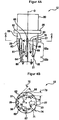
  • 4A ist ein Längsschnitt eines Laserbearbeitungskopfs bei einer dritten Ausführungsform. 4A is a longitudinal section of a laser processing head in a third embodiment.
  • 4B ist ein Querschnitt des Laserbearbeitungskopfs, der der Schnittlinie C-C in 4A entspricht. 4B is a cross section of the laser processing head, the section line CC in 4A equivalent.

Ausführliche ErklärungDetailed explanation

Nachstehend werden Ausführungsformen der vorliegenden Offenbarung unter Bezugnahme auf die beiliegenden Zeichnungen ausführlich erklärt. In den einzelnen Zeichnungen sind gleiche oder ähnliche Aufbauelemente mit gleichen oder ähnlichen Bezugszeichen versehen. Die nachstehend besprochenen Ausführungsformen stellen keine Beschränkung des technischen Gebiets und der Bedeutung der Terminologie der in den Patentansprüchen beschriebenen Erfindung dar. Die Ausdrücke „oben“ und „stromaufwärts“ in der vorliegenden Beschreibung verweisen auf die stromaufwärts befindliche Seite auf dem Pfad des in der Vorwärtsrichtung verlaufenden Laserlichts, und die Ausdrücke „unten“ und „stromabwärts“ verweisen auf die stromabwärts befindliche Seite auf dem Pfad des in der Vorwärtsrichtung verlaufenden Laserlichts.Hereinafter, embodiments of the present disclosure will be explained in detail with reference to the accompanying drawings. In the individual drawings, the same or similar structural elements are provided with the same or similar reference numerals. The embodiments discussed below do not limit the technical scope and meaning of the terminology of the invention described in the claims. The terms "up" and "upstream" in the present specification refer to the upstream side on the path of the forward direction Laser light, and the terms "down" and "downstream" refer to the downstream side on the path of the forward laser light.

1 ist eine schematische Ansicht, die den schematischen Aufbau einer Laserbearbeitungsvorrichtung 10 nach einer Ausführungsform zeigt. Die Laserbearbeitungsvorrichtung 10 umfasst einen Laseroszillator 11, einen Laserbearbeitungskopf 12, der Laserlicht von dem Laseroszillator 11 leitet und zu einem zu bearbeitenden Material 15 strahlt, eine numerische Steuervorrichtung 13, die die gesamte Laserbearbeitungsvorrichtung 10 steuert, und eine Antriebssteuervorrichtung 14, die den Antrieb einer X-Achse, einer Y-Achse und einer Z-Achse eines Bearbeitungstischs 16 und den Antrieb einer V-Achse einer Sammellinse 24 steuert. Der Laserbearbeitungskopf 12 umfasst einen hohlen zylinderförmigen Kopfhauptkörper 20 und eine Düse 22, die an den Kopfhauptkörper 20 angeschlossen ist und ein Hilfsgas von einer Ausströmöffnung 21 gegen das zu bearbeitende Material 15 bläst. 1 is a schematic view showing the schematic structure of a laser processing apparatus 10 according to one embodiment shows. The laser processing device 10 includes a laser oscillator 11 , a laser processing head 12 , the laser light from the laser oscillator 11 leads and to a material to be processed 15 radiates, a numerical control device 13 covering the entire laser processing device 10 controls, and a drive control device 14 that drive a X -Axis, one Y Axis and one Z -Axis of a machining table 16 and the drive of a V Axis of a condenser lens 24 controls. The laser processing head 12 comprises a hollow cylindrical head main body 20 and a nozzle 22 attached to the head main body 20 is connected and an auxiliary gas from an exhaust port 21 against the material to be processed 15 blows.

Der Kopfhauptkörper 20 umfasst eine Kollimationslinse 23, die das Laserlicht von dem Laseroszillator 11 zu parallelem Licht ausführt, die Sammellinse 24, die das Laserlicht an dem zu bearbeitenden Material 15 sammelt, und ein Schutzfenster 25, das die Sammellinse 24 vor Teilchen schützt. Das Schutzfenster 25 ist aus einem durch eine Reflexionsbeschichtung oberflächenbehandelten Glasmaterial oder dergleichen gebildet und verschließt das Innere des Kopfhauptkörpers 20, damit keine Teilchen an der Sammellinse 24 anhaften. Das Schutzfenster 25 ist in Bezug auf die optische Achse des Laserlichts senkrecht angeordnet, kann in Bezug auf die optische Achse des Laserlichts aber auch in einem Winkel von 15 Grad oder mehr geneigt sein. Dadurch wird der Auftreffwinkel von Teilchen, die während der Laserbearbeitung zu dem Schutzfenster 25 fliegen, flach und kann eine Verschmutzung des Schutzfensters 25 unterdrückt werden.The head main body 20 includes a collimating lens 23 receiving the laser light from the laser oscillator 11 to parallel light, the condenser lens 24 that the laser light on the material to be processed 15 collects, and a protective window 25 that the condenser lens 24 protects against particles. The protection window 25 is formed of a glass material or the like surface-treated by a reflection coating and closes the inside of the head main body 20 , so no particles on the condenser lens 24 adhere. The protection window 25 is perpendicular with respect to the optical axis of the laser light, but may be inclined with respect to the optical axis of the laser light but also at an angle of 15 degrees or more. As a result, the angle of incidence of particles that during the laser processing to the protective window 25 fly, flat and may cause pollution of the protective window 25 be suppressed.

2A ist ein Längsschnitt des Laserbearbeitungskopfs 12 bei einer ersten Ausführungsform. Der Laserbearbeitungskopf 12 umfasst ferner eine Kammer 26, die den Raum zwischen dem Schutzfenster 25 und der Düse 22 definiert, eine Einströmöffnung 27, die in der Kammer 26 angeordnet ist und ein Hilfsgas 30 einbringt, und einen Stromteilungsvorsprung 28, der an einer der Einströmöffnung 27 gegenüberliegenden Position angeordnet ist. Die Richtung der Einströmöffnung 27 für das Hilfsgas bildet mit der Richtung der Ausströmöffnung 21 für das Hilfsgas einen rechten Winkel. Da der Stromteilungsvorsprung 28 an einer Stelle ausgebildet wird, an der das Hilfsgas 30 auf die Innenwand der Kammer 26 traf und ein turbulenter Strom erzeugt wurde, wird ein turbulenter Strom des Hilfsgases 30 unterdrückt. 2A is a longitudinal section of the laser processing head 12 in a first embodiment. The laser processing head 12 further comprises a chamber 26 that the space between the protective window 25 and the nozzle 22 defines an inflow opening 27 in the chamber 26 is arranged and an auxiliary gas 30 contributes, and a Stromteilungsvorsprung 28 , at one of the inlet opening 27 is arranged opposite position. The direction of the inflow opening 27 for the auxiliary gas forms with the direction of the discharge opening 21 for the auxiliary gas a right angle. Since the Stromteilungsvorsprung 28 is formed at a position where the auxiliary gas 30 on the inner wall of the chamber 26 met and a turbulent stream was generated, becomes a turbulent flow of the auxiliary gas 30 suppressed.

2B ist ein Querschnitt des Laserbearbeitungskopfs 12, der der Schnittlinie A-A in 2A entspricht. Der Stromteilungsvorsprung 28 weist eine zu der Einströmöffnung 27 hin schmäler werdende sich verjüngende Form, zum Beispiel die Form einer dreieckigen Säule, auf. Der Stromteilungsvorsprung 28 teilt das Hilfsgas 30 in einen ersten Strom 31 und einen zweiten Strom 32, die entlang der Umfangsrichtung der optischen Achse O des Laserlichts fließen. Da das Hilfsgas 30, dessen Strom geteilt wurde, zu der Seite der Einströmöffnung 27 zurückkehrt, entsteht auf Seiten der Einströmöffnung 27 kein niedriger Druck und wird die unausgewogene Verteilung des Drucks in der Kammer verringert. Da es folglich in dem von dem Düsenspitzenende ausgestoßenen Hilfsgas kaum zu einer Unausgewogenheit kommt, trifft das Hilfsgas gleichmäßig auf das zu bearbeitende Material und kann die Qualität der Laserbearbeitung erhöht werden. 2 B is a cross section of the laser processing head 12 , the section line AA in 2A equivalent. The current sharing lead 28 has one to the inflow opening 27 narrowing tapering shape, for example, the shape of a triangular column on. The current sharing lead 28 shares the auxiliary gas 30 into a first stream 31 and a second stream 32 along the circumferential direction of the optical axis O of the laser light flow. Because the auxiliary gas 30 , whose stream has been divided, to the side of the inflow opening 27 returns, arises on the side of the inflow opening 27 no low pressure and reduces the unbalanced distribution of pressure in the chamber. As a result, since there is hardly any imbalance in the auxiliary gas discharged from the nozzle tip end, the assist gas uniformly strikes the material to be processed, and the quality of the laser processing can be increased.

Wie in 2B gezeigt ist es günstig, wenn die Mittelposition der Einströmöffnung 27, die optische Achse O des Laserlichts, und die Position des Spitzenendes des Stromteilungsvorsprungs 28 auf einer geraden Linie angeordnet sind. Da der Stromteilungsvorsprung 28 das Hilfsgas 30 dadurch gleichmäßig nach links und rechts verteilt, erreicht das Fließmengenverhältnis des ersten Stroms 31 und des zweiten Stroms 32 1 : 1 und kann der Druck im Inneren der Kammer 26 gleichmäßig gestaltet werden.As in 2 B it is shown favorably when the center position of the inflow opening 27 , the optical axis O of the laser light, and the position of the tip end of the current-splitting protrusion 28 arranged on a straight line. Since the Stromteilungsvorsprung 28 the auxiliary gas 30 thereby evenly distributed to the left and right reaches the flow amount ratio of the first stream 31 and the second stream 32 1: 1 and can the pressure inside the chamber 26 be designed uniformly.

Wie in 2A gezeigt weisen die Einströmöffnung 27 und der Stromteilungsvorsprung 28 in der zu der optischen Achse O des Laserlichts parallelen Richtung jeweils eine erste Breite 33, 34 auf, und ist die erste Breite 33 der Einströmöffnung 27 vorzugsweise kleiner als die erste Breite 34 des Stromteilungsvorsprungs 28 ausgeführt. Dadurch trifft der Großteil des Hilfsgases 30 von der Einströmöffnung 27 auf den Stromteilungsvorsprung 28 und wird ein turbulenter Strom im Inneren der Kammer 26 unterdrückt.As in 2A shown have the inlet opening 27 and the current splitting protrusion 28 in the to the optical axis O the laser light parallel direction in each case a first width 33 . 34 on, and is the first width 33 the inflow opening 27 preferably smaller than the first width 34 the current division projection 28 executed. As a result, the majority of the auxiliary gas hits 30 from the inlet opening 27 on the current sharing lead 28 and becomes a turbulent stream inside the chamber 26 suppressed.

Wie in 2B gezeigt weisen die Einströmöffnung 27 und der Stromteilungsvorsprung 28 in der zu der optischen Achse O des Laserlichts senkrechten Richtung jeweils eine zweite Breite 35, 36 auf, und ist die zweite Breite 35 der Einströmöffnung 27 vorzugsweise kleiner als die zweite Breite 36 des Stromteilungsvorsprungs 28 ausgeführt. Dadurch trifft der Großteil des Hilfsgases 30 von der Einströmöffnung 27 auf den Stromteilungsvorsprung 28 und wird ein turbulenter Strom im Inneren der Kammer 26 unterdrückt.As in 2 B shown have the inlet opening 27 and the current splitting protrusion 28 in the to the optical axis O the laser light vertical direction each have a second width 35 . 36 on, and is the second width 35 the inflow opening 27 preferably smaller than the second width 36 the current division projection 28 executed. As a result, the majority of the auxiliary gas hits 30 from the inlet opening 27 on the current sharing lead 28 and becomes a turbulent stream inside the chamber 26 suppressed.

2C ist eine von der Einströmöffnung 27 des Hilfsgases her gesehene Vorderansicht des Stromteilungsvorsprungs 28. Da der Stromteilungsvorsprung 28 wie oben erwähnt die Form einer dreieckigen Säule aufweist, teilt er den Strom des Hilfsgases in der zu der optischen Achse O des Laserlichts senkrechten Umfangsrichtung, das heißt, in einen rechtsdrehend fließenden ersten Strom 31 und einen linksdrehend fließenden zweiten Strom 32. Das Hilfsgas, dessen Strom geteilt wurde, fließt nach der Rückkehr zu der Seite der Einströmöffnung von dem Inneren der Kammer mit einem hohen Druck zu der Ausströmöffnung mit einem niedrigen Druck. Damit das Fließmengenverhältnis des ersten Stroms 31 und des zweiten Stroms 32 1 : 1 erreicht, beträgt vorzugsweise auch das Flächenverhältnis der beiden Flächen des Stromteilungsvorsprungs 28, auf die der erste Strom 31 und der zweite Strom 32 treffen, 1 : 1. 2C is one of the inflow port 27 the auxiliary gas ago seen front view of the Stromteilungsvorsprungs 28 , Since the Stromteilungsvorsprung 28 As mentioned above, having the shape of a triangular column, it divides the flow of the auxiliary gas in the direction of the optical axis O of the laser light vertical circumferential direction, that is, in a right-handed flowing first stream 31 and a left-handed flowing second stream 32 , The auxiliary gas whose flow has been divided flows, after returning to the side of the inflow port, from the inside of the high-pressure chamber to the low-pressure outflow port. So that the flow rate ratio of the first stream 31 and the second stream 32 1: 1 is reached, is preferably also the area ratio of the two surfaces of the flow splitting projection 28 to which the first stream 31 and the second stream 32 meet, 1: 1.

2D ist eine Vorderansicht, die ein Abwandlungsbeispiel des von der Einströmöffnung 27 des Hilfsgases her gesehenen Stromteilungsvorsprungs 29 zeigt. Der Stromteilungsvorsprung 29 kann eine zu der Ausströmöffnung der Düse hin schmäler werdende sich verjüngende Form, zum Beispiel die Form einer dreieckigen Pyramide, aufweisen. Der Stromteilungsvorsprung 29 teilt den Strom des Hilfsgases in der Umfangsrichtung der optischen Achse O des Laserlichts, das heißt, in einen nach rechts unten drehend fließenden ersten Strom 37 und einen nach links unten drehend fließenden zweiten Strom 38. Da das Hilfsgas, dessen Strom geteilt wurde, so gleichgerichtet wird, dass es stromabwärts gerichtet wird, wird ein turbulenter Strom im Inneren der Kammer 26 noch stärker unterdrückt. Damit das Fließmengenverhältnis des ersten Stroms 37 und des zweiten Stroms 38 1 : 1 erreicht, beträgt vorzugsweise auch das Flächenverhältnis der beiden Flächen des Stromteilungsvorsprungs 29, auf die der erste Strom 37 und der zweite Strom 38 treffen, 1 : 1. 2D FIG. 16 is a front view showing a modification example of the inflow port. FIG 27 the auxiliary gas ago seen Stromteilungsvorsprungs 29 shows. The current sharing lead 29 For example, a tapered shape, for example, the shape of a triangular pyramid, may be narrowed toward the discharge opening of the nozzle. The current sharing lead 29 divides the flow of the auxiliary gas in the circumferential direction of the optical axis O of the laser light, that is, in a first current flowing down to the right 37 and a second current flowing to the left bottom 38 , Since the auxiliary gas, whose flow has been split, is rectified to be directed downstream, a turbulent flow becomes inside the chamber 26 even more suppressed. So that the flow rate ratio of the first stream 37 and the second stream 38 1 1 reaches, preferably, the area ratio of the two surfaces of the flow splitting protrusion 29 to which the first stream 37 and the second stream 38 meet, 1: 1.

2E ist eine Vorderansicht, die ein Abwandlungsbeispiel des von der Einströmöffnung 27 des Hilfsgases her gesehenen Stromteilungsvorsprungs 52 zeigt. Der Stromteilungsvorsprung 52 kann eine zu der Einströmöffnung 27 hin schmäler werdende sich verjüngende Form, zum Beispiel die Form einer viereckigen Pyramide mit der Spitze 55 an der stromaufwärts gelegenen Seite, aufweisen. Der Stromteilungsvorsprung 52 teilt den Strom des Hilfsgases nicht nur in der Umfangsrichtung der optischen Achse O, das heißt, in einen rechtsdrehend fließenden ersten Strom 53 und einen linksdrehend fließenden zweiten Strom 54, sondern auch in einen stromabwärts fließenden neunten Strom 56. Das Fließmengenverhältnis des ersten Stroms 53, des zweiten Stroms 54 und des neunten Stroms 56 beträgt vorzugsweise 1 : 1 : 2. Damit das Fließmengenverhältnis des ersten Stroms 53, des zweiten Stroms 54 und des neunten Stroms 56 1 : 1 : 2 beträgt, beträgt vorzugsweise auch das Verhältnis der drei Flächen des Stromteilungsvorsprungs 52, auf die der erste Strom 53, der zweite Strom 54 und der neunte Strom 56 treffen, 1 : 1 : 2. 2E FIG. 16 is a front view showing a modification example of the inflow port. FIG 27 the auxiliary gas ago seen Stromteilungsvorsprungs 52 shows. The current sharing lead 52 can one to the inlet opening 27 Narrowing tapered shape, for example, the shape of a square pyramid with the top 55 on the upstream side. The current sharing lead 52 not only divides the flow of the auxiliary gas in the circumferential direction of the optical axis O That is, in a right-handed flowing first stream 53 and a left-handed flowing second stream 54 but also into a ninth stream flowing downstream 56 , The flow rate ratio of the first stream 53 , the second stream 54 and the ninth stream 56 is preferably 1: 1: 2. Thus, the flow rate ratio of the first stream 53 , the second stream 54 and the ninth stream 56 1: 1: 2, is preferably also the ratio of the three surfaces of the flow splitting projection 52 to which the first stream 53 , the second stream 54 and the ninth stream 56 meet, 1: 1: 2.

3A ist ein Längsschnitt eines Laserbearbeitungskopfs 12 bei einer zweiten Ausführungsform, und 3B ist ein Querschnitt des Laserbearbeitungskopfs, der der Schnittlinie B-B in 3A entspricht. Es versteht sich, dass nachstehend nur jene Bereiche erklärt werden, die sich von dem Laserbearbeitungskopf bei der ersten Ausführungsform unterscheiden, und auf eine Erklärung von gleichen Bereichen verzichtet wird. Der Laserbearbeitungskopf 12 bei der zweiten Ausführungsform umfasst nicht nur den oben beschriebenen Stromteilungsvorsprung 29, sondern auch eine erste Gruppe von Gleichrichtungsvorsprüngen 42, 43, die an beiden Seiten des Stromteilungsvorsprungs 29 parallel zu der optischen Achse O des Laserlichts verlaufen und wenigstens einen Teil des ersten Stroms 37 und des zweiten Stroms 38 zu einem zu der Ausströmöffnung 21 der Düse 22 gerichteten dritten Strom 40 und vierten Strom 41 gleichrichten. Außerdem umfasst der Laserbearbeitungskopf 12 eine zweite Gruppe von Gleichrichtungsvorsprüngen 46, 47, die näher als die erste Gruppe von Gleichrichtungsvorsprüngen 42, 43 an der Seite der Einströmöffnung 27 angeordnet sind, parallel zu der optischen Achse O des Laserlichts verlaufen und wenigstens einen Teil des ersten Stroms 37 und des zweiten Stroms 38 zu einem zu der Ausströmöffnung 21 der Düse 22 gerichteten fünften Strom 44 und sechsten Strom 45 gleichrichten. Überdies umfasst der Laserbearbeitungskopf 12 eine dritte Gruppe von Gleichrichtungsvorsprüngen 50, 51, die näher als die zweite Gruppe von Gleichrichtungsvorsprüngen 46, 47 an der Seite der Einströmöffnung 27 angeordnet sind, parallel zu der optischen Achse O des Laserlichts verlaufen und wenigstens einen Teil des ersten Stroms 37 und des zweiten Stroms 38 zu einem zu der Ausströmöffnung 21 der Düse 22 gerichteten siebenten Strom 48 und achten Strom 49 gleichrichten. 3A is a longitudinal section of a laser processing head 12 in a second embodiment, and 3B is a cross section of the laser processing head, the section line BB in 3A equivalent. It is understood that only those portions different from the laser processing head in the first embodiment will be explained below, and an explanation of the same ranges will be omitted. The laser processing head 12 in the second embodiment, not only includes the above-described current-splitting protrusion 29 , but also a first group of rectification protrusions 42 . 43 on either side of the flow splitting tab 29 parallel to the optical axis O of the laser light and at least part of the first current 37 and the second stream 38 to one to the discharge opening 21 the nozzle 22 directed third stream 40 and fourth stream 41 rectify. In addition, the laser processing head includes 12 a second group of rectification protrusions 46 . 47 closer than the first group of rectification protrusions 42 . 43 on the side of the inflow opening 27 are arranged, parallel to the optical axis O of the laser light and at least part of the first current 37 and the second stream 38 to one to the discharge opening 21 the nozzle 22 directed fifth stream 44 and sixth electricity 45 rectify. Moreover, the laser processing head comprises 12 a third group of rectification protrusions 50 . 51 closer than the second group of rectification protrusions 46 . 47 on the side of the inflow opening 27 are arranged, parallel to the optical axis O of the laser light and at least part of the first current 37 and the second stream 38 to one to the discharge opening 21 the nozzle 22 directed seventh stream 48 and pay attention to electricity 49 rectify.

Wie in 3A gezeigt beschränken die erste Gruppe von Gleichrichtungsvorsprüngen 42, 43, die zweite Gruppe von Gleichrichtungsvorsprüngen 46, 47 und die dritte Gruppe von Gleichrichtungsvorsprüngen 50, 51 die Bewegung des im Inneren des Laserbearbeitungskopfs 12 wirbelnden Hilfsgases 30 und richten sie das Hilfsgas 30 geradeaus zu der Ausströmöffnung 21 der Düse 22. Da das von der Düse 22 ausgestoßene Hilfsgas im Großen und Ganzen senkrecht auf das zu bearbeitende Material trifft, wird eine Druckabnahme des Hilfsgases in Bezug auf das zu bearbeitende Material verhindert.As in 3A shown restrict the first group of rectification protrusions 42 . 43 , the second group of rectification tabs 46 . 47 and the third group of rectification protrusions 50 . 51 the movement of the inside of the laser processing head 12 swirling auxiliary gases 30 and set up the auxiliary gas 30 straight ahead to the discharge opening 21 the nozzle 22 , Because of the nozzle 22 ejected auxiliary gas meets by and large perpendicular to the material to be processed, a decrease in pressure of the auxiliary gas is prevented in relation to the material to be processed.

Wie in 3B gezeigt sind die die erste Gruppe von Gleichrichtungsvorsprüngen 42, 43, die zweite Gruppe von Gleichrichtungsvorsprüngen 46, 47 und die dritte Gruppe von Gleichrichtungsvorsprüngen 50, 51 in der Umfangsrichtung der optischen Achse O des Laserlichts vorzugsweise in gleichen Abständen angeordnet und zu Beispiel jeweils in Mittelpunktswinkeln von 45 Grad angeordnet. Dadurch wird die Unausgewogenheit des Drucks im Inneren des Laserbearbeitungskopfs 12 noch weiter verringert.As in 3B shown are the first group of rectification protrusions 42 . 43 , the second group of rectification tabs 46 . 47 and the third group of rectification protrusions 50 . 51 in the circumferential direction of the optical axis O of the laser light are preferably arranged at equal intervals and arranged, for example, at center angles of 45 degrees. This will increase the imbalance of pressure inside the laser processing head 12 even further reduced.

4A ist ein Längsschnitt eines Laserbearbeitungskopfs 12 bei einer dritten Ausführungsform, und 4B ist ein Querschnitt des Laserbearbeitungskopfs 12, der der Schnittlinie C-C in 4A entspricht. Es versteht sich, dass nachstehend nur jene Bereiche erklärt werden, die sich von dem Laserbearbeitungskopf bei der zweiten Ausführungsform unterscheiden, und auf eine Erklärung von gleichen Bereichen verzichtet wird. Eine erste Gruppe von Gleichrichtungsvorsprüngen 62, 63, eine zweite Gruppe von Gleichrichtungsvorsprüngen 66, 67 und eine dritte Gruppe von Gleichrichtungsvorsprüngen 70, 71 bei der dritten Ausführungsform weisen eine zu der Ausströmöffnung 21 der Düse 22 hin schmäler werdende sich verjüngende Form, zum Beispiel die Form einer dreieckigen Säule, auf. Da das Hilfsgas 30 dadurch so gleichgerichtet wird, dass es stromabwärts gerichtet wird, wird ein turbulenter Strom im Inneren der Kammer 26 noch stärker unterdrückt. 4A is a longitudinal section of a laser processing head 12 in a third embodiment, and 4B is a cross section of the laser processing head 12 , the section line CC in 4A equivalent. It is understood that only those portions different from the laser processing head in the second embodiment will be explained below, and an explanation of the same ranges will be omitted. A first group of rectification tabs 62 . 63 , a second group of rectification protrusions 66 . 67 and a third group of rectification protrusions 70 . 71 in the third embodiment, one to the discharge opening 21 the nozzle 22 narrowing tapering shape, for example, the shape of a triangular column on. Because the auxiliary gas 30 is rectified so that it is directed downstream, a turbulent flow in the interior of the chamber 26 even more suppressed.

Wie in 4B gezeigt weisen die erste Gruppe von Gleichrichtungsvorsprüngen 62, 63, die zweite Gruppe von Gleichrichtungsvorsprüngen 66, 67 und die dritte Gruppe von Gleichrichtungsvorsprüngen 70 71 in der zu der optischen Achse O des Laserlichts gewandten Richtung eine jeweils dritte Breite 72, 73, 74 auf, und ist vorzugsweise die dritte Breite 72, der ersten Gruppe von Gleichrichtungsvorsprüngen 62, 63 kleiner als die dritte Breite 73 der zweiten Gruppe von Gleichrichtungsvorsprüngen 66, 67 und die dritte Breite 73 der zweiten Gruppe von Gleichrichtungsvorsprüngen 66, 67 kleiner als die dritte Breite 74 der dritten Gruppe von Gleichrichtungsvorsprüngen 70, 71. Dadurch werden der durch den Stromteilungsvorsprung 29 abgeteilte erste Strom 37 und zweite Strom 38 durch die zweite Gruppe von Gleichrichtungsvorsprüngen 66, 67 gleichgerichtet, sofern sie nicht durch die erste Gruppe von Gleichrichtungsvorsprüngen 62, 63 gleichgerichtet wurden, und durch die dritte Gruppe von Gleichrichtungsvorsprüngen 70, 71 gleichgerichtet, sofern sie nicht durch die zweite Gruppe von Gleichrichtungsvorsprüngen 66, 67 gleichgerichtet wurden. Das heißt, da die gesamte Fließmenge des ersten Stroms 37 und des zweiten Stroms 38 der gesamten Fließmenge von dem dritten Strom 60 bis zu dem achten Strom 69 gleich wird, wird das Hilfsgas im Inneren der Kammer 26 noch stärker gleichgerichtet.As in 4B show the first group of rectification protrusions 62 . 63 , the second group of rectification tabs 66 . 67 and the third group of rectification protrusions 70 71 in the to the optical axis O of the laser light direction each have a third width 72 . 73 . 74 on, and is preferably the third width 72 , the first group of rectification tabs 62 . 63 smaller than the third width 73 the second group of rectification tabs 66 . 67 and the third width 73 the second group of rectification tabs 66 . 67 smaller than the third width 74 the third group of rectification tabs 70 . 71 , This will be the through the flow splitting projection 29 split first stream 37 and second stream 38 through the second group of rectification protrusions 66 . 67 rectified unless provided by the first set of rectification protrusions 62 . 63 rectified and through the third group of rectification protrusions 70 . 71 rectified unless provided by the second set of rectification protrusions 66 . 67 rectified. That is, because the total flow of the first stream 37 and the second stream 38 the total flow of the third stream 60 up to the eighth stream 69 becomes equal, the auxiliary gas is inside the chamber 26 even more rectified.

Wie in 4A gezeigt ist es günstig, wenn die Düse 22 einen Kegelabschnitt 22a und einen an den Kegelabschnitt 22a angeschlossenen Zylinderabschnitt 22b aufweist und die Ausströmöffnung 21 des Hilfsgases in dem Zylinderabschnitt 22b gebildet ist. Da die Gleichrichtung so erfolgt, dass der Zylinderabschnitt 22b das Hilfsgas von der Ausströmöffnung 21 der Düse 22 gerade ausstößt, trifft das Hilfsgas in Bezug auf das zu bearbeitende Material im Großen und Ganzen senkrecht auf und wird die Qualität der Laserbearbeitung verbessert.As in 4A it is shown favorably when the nozzle 22 a cone section 22a and one to the cone section 22a connected cylinder section 22b has and the outflow opening 21 the auxiliary gas in the cylinder portion 22b is formed. Since the rectification is done so that the cylinder section 22b the auxiliary gas from the discharge opening 21 the nozzle 22 just ejects, the auxiliary gas applies generally perpendicular to the material to be processed and the quality of the laser processing is improved.

Bei den oben beschriebenen Ausführungsformen ist der Durchmesser der Ausströmöffnung 21 des Hilfsgases größer als der Durchmesser der Einströmöffnung 27 des Hilfsgases, doch bei anderen Ausführungsformen ist es besser, wenn der Durchmesser der Ausströmöffnung 21 des Hilfsgases kleiner als der Durchmesser der Einströmöffnung 27 des Hilfsgases Dadurch wird der Druck des von der Düse 22 ausgestoßenen Hilfsgases erhöht und die Kraft zum Wegblasen von geschmolzenem Material vergrößert.In the embodiments described above, the diameter of the outflow opening 21 the auxiliary gas is greater than the diameter of the inflow opening 27 the auxiliary gas, but in other embodiments it is better if the diameter of the outflow opening 21 the auxiliary gas is smaller than the diameter of the inflow opening 27 of the auxiliary gas This will reduce the pressure of the nozzle 22 expelled auxiliary gas and increases the power to blow away molten material.

Da gemäß dem oben beschriebenen Laserbearbeitungskopf 12 an jener Stelle, an der das Hilfsgas 30 auf die Innenwand der Kammer 26 traf und ein turbulenter Strom erzeugt wurde, ein Stromteilungsvorsprung 28, 29 ausgebildet wird, wird das Hilfsgas 30 in der Umfangsrichtung der optischen Achse O des Laserlichts gleichgerichtet. Da das gleichgerichtete Hilfsgas 30 zu der Seite der Einströmöffnung 27 zurückkehrt, kommt es an der Seite der Einströmöffnung 27 nicht zu einer Druckabnahme und nimmt die Unausgewogenheit des Drucks im Inneren der Kammer 26 ab. Da es folglich in dem von dem Düsenspitzenende ausgestoßenen Hilfsgas kaum zu einer Unausgewogenheit kommt, trifft das Hilfsgas gleichmäßig auf das zu bearbeitende Material und kann die Qualität der Laserbearbeitung erhöht werden.As according to the laser processing head described above 12 at the point where the auxiliary gas 30 on the inner wall of the chamber 26 met and a turbulent stream was generated, a stream splitting projection 28 . 29 is formed, the auxiliary gas 30 rectified in the circumferential direction of the optical axis O of the laser light. Because the rectified auxiliary gas 30 to the side of the inflow opening 27 returns, it comes to the side of the inlet 27 not to a decrease in pressure and takes the imbalance of pressure inside the chamber 26 from. As a result, since there is hardly any imbalance in the auxiliary gas discharged from the nozzle tip end, the assist gas uniformly strikes the material to be processed, and the quality of the laser processing can be increased.

In der vorliegenden Beschreibung wurden verschiedene Ausführungsformen erklärt, doch versteht sich, dass die vorliegende Erfindung nicht auf die verschiedenen oben beschriebenen Ausführungsformen beschränkt ist, sondern innerhalb des Umfangs, der in den folgenden Patentansprüchen angegeben ist, verschiedene Änderungen vorgenommen werden können.Various embodiments have been explained in the present specification, but it should be understood that the present invention is not limited to the various embodiments described above, but various changes can be made within the scope indicated in the following claims.

Claims (15)

Laserbearbeitungskopf (12) mit der Funktion des Gleichrichtens von Hilfsgas, dadurch gekennzeichnet, dass der Laserbearbeitungskopf ein Schutzfenster (25); eine Düse (22), die ein Hilfsgas zu einem zu bearbeitenden Material bläst; eine Kammer (26), die den Raum zwischen dem Schutzfenster und der Düse definiert; eine Einströmöffnung (27), die in der Kammer angeordnet ist und das Hilfsgas einbringt; und einen Stromteilungsvorsprung (28; 29; 52), der an einer der Einströmöffnung gegenüberliegenden Position angeordnet ist und das Hilfsgas von der Einströmöffnung in einen ersten Strom (31; 37; 53) und einen zweiten Strom (32; 38; 54), die entlang der Umfangsrichtung einer optischen Achse des Laserlichts flie-βen, teilt, umfasst.Laser processing head (12) having the function of rectifying auxiliary gas, characterized in that the laser processing head has a protective window (25); a nozzle (22) blowing an auxiliary gas to a material to be processed; a chamber (26) defining the space between the protective window and the nozzle; an inflow port (27) disposed in the chamber and introducing the assist gas; and a flow splitting protrusion (28; 29; 52) disposed at a position opposite to the inflow port and the assist gas from the inflow port into a first flow (31; 37; 53) and a second flow (32; 38; 54) along the circumferential direction of an optical axis of the laser light flie-βen, divides. Laserbearbeitungskopf nach Anspruch 1, wobei der Stromteilungsvorsprung (28; 29; 52) eine zu der Einströmöffnung (27) hin schmäler werdende sich verjüngende Form aufweist.Laser processing head after Claim 1 wherein the flow splitting protrusion (28; 29; 52) has a tapered shape narrowing towards the inflow opening (27). Laserbearbeitungskopf nach Anspruch 2, wobei der Stromteilungsvorsprung (29; 52) eine zu der Ausströmöffnung (21) der Düse hin schmäler werdende sich verjüngende Form aufweist.Laser processing head after Claim 2 wherein the flow splitting projection (29; 52) has a tapered shape narrowing toward the discharge port (21) of the nozzle. Laserbearbeitungskopf nach Anspruch 1, ferner umfassend eine erste Gruppe von Gleichrichtungsvorsprüngen (42, 43), die an beiden Seiten des Stromteilungsvorsprungs (29) parallel zu der optischen Achse (0) des Laserlichts verlaufen und wenigstens einen Teil des ersten Stroms (37) und des zweiten Stroms (38) zu einem zu der Ausströmöffnung (21) der Düse gerichteten dritten Strom (40) und vierten Strom (41) gleichrichten.Laser processing head after Claim 1 , further comprising a first group of rectifying protrusions (42, 43) extending on both sides of the current splitting protrusion (29) parallel to the optical axis (0) of the laser light and including at least part of the first current (37) and the second current (38 ) to a third stream (40) and fourth stream (41) directed to the discharge port (21) of the nozzle. Laserbearbeitungskopf nach Anspruch 4, ferner umfassend eine zweite Gruppe von Gleichrichtungsvorsprüngen (46, 47), die näher als die erste Gruppe von Gleichrichtungsvorsprüngen (42, 43) an der Seite der Einströmöffnung (27) angeordnet sind, parallel zu der optischen Achse (0) des Laserlichts verlaufen und wenigstens einen Teil des ersten Stroms (37) und des zweiten Stroms (38) zu einem zu der Ausströmöffnung (21) der Düse gerichteten fünften Strom (44) und sechsten Strom (45) gleichrichten.Laser processing head after Claim 4 further comprising a second group of rectification protrusions (46, 47) located closer than the first group of rectification protrusions (42, 43) on the side of the inflow port (27), parallel to the optical axis (0) of the laser light, and rectifying at least a portion of the first stream (37) and the second stream (38) to a fifth stream (44) and sixth stream (45) directed toward the discharge port (21) of the nozzle. Laserbearbeitungskopf nach Anspruch 5, ferner umfassend eine dritte Gruppe von Gleichrichtungsvorsprüngen (50, 51), die näher als die zweite Gruppe von Gleichrichtungsvorsprüngen (4, 47) an der Seite der Einströmöffnung (27) angeordnet sind, parallel zu der optischen Achse (O) des Laserlichts verlaufen und wenigstens einen Teil des ersten Stroms (37) und des zweiten Stroms (38) zu einem zu der Ausströmöffnung (21) der Düse gerichteten siebenten Strom (48) und achten Strom (49) gleichrichten.Laser processing head after Claim 5 further comprising a third group of rectifying protrusions (50, 51) located closer than the second group of rectifying protrusions (4, 47) on the side of the inflow port (27), parallel to the optical axis (O) of the laser light, and rectify at least a portion of the first stream (37) and the second stream (38) to a seventh stream (48) directed toward the discharge port (21) of the nozzle and eighth stream (49). Laserbearbeitungskopf nach Anspruch 6, wobei die erste Gruppe von Gleichrichtungsvorsprüngen (42, 43), die zweite Gruppe von Gleichrichtungsvorsprüngen (46, 47) und die dritte Gruppe von Gleichrichtungsvorsprüngen (50, 51) eine zu der Ausströmöffnung (21) der Düse hin schmäler werdende sich verjüngende Form aufweisen.Laser processing head after Claim 6 wherein the first group of rectification protrusions (42, 43), the second group of rectification protrusions (46, 47), and the third group of rectification protrusions (50, 51) have a tapered shape narrowing toward the nozzle discharge port (21) , Laserbearbeitungskopf nach einem der Ansprüche 1 bis 7, wobei das Fließmengenverhältnis des ersten Stroms (37) und des zweiten Stroms (38) 1 : 1 beträgt.Laser processing head according to one of the Claims 1 to 7 , wherein the flow ratio of the first current (37) and second current (38) is 1: 1. Laserbearbeitungskopf nach Anspruch 6 oder 7, wobei der Stromteilungsvorsprung (52) die Form einer viereckigen Pyramide mit der Spitze (55) an der stromaufwärts gelegenen Seite aufweist und das Hilfsgas außerdem in einen zu der stromabwärts befindlichen Seite fließenden neunten Strom (56) teilt, wobei das Fließmengenverhältnis des ersten Stroms (53), des zweiten Stroms (54) und des neunten Stroms (56) 1 : 1 : 2 beträgtLaser processing head after Claim 6 or 7 wherein the flow splitting protrusion (52) is in the form of a quadrangular pyramid having the tip (55) on the upstream side and dividing the assist gas into a ninth flow (56) flowing to the downstream side, wherein the flow rate ratio of the first flow (52) 53), the second stream (54) and the ninth stream (56) is 1: 1: 2 Laserbearbeitungskopf nach einem der Ansprüche 1 bis 9, wobei die Düse (22) einen Kegelabschnitt (22a) und einen an den Kegelabschnitt angeschlossenen Zylinderabschnitt (22b) aufweist und die Ausströmöffnung (21) des Hilfsgases in dem Zylinderabschnitt (22b) gebildet ist.Laser processing head according to one of the Claims 1 to 9 wherein the nozzle (22) has a cone portion (22a) and a cylinder portion (22b) connected to the cone portion, and the discharge port (21) of the auxiliary gas is formed in the cylinder portion (22b). Laserbearbeitungskopf nach einem der Ansprüche 1 bis 10, wobei die Mittelposition der Einströmöffnung (27), die optische Achse (O) des Laserlichts, und die Spitzenendposition (28a) des Stromteilungsvorsprungs (28) auf einer geraden Linie angeordnet sind.Laser processing head according to one of the Claims 1 to 10 wherein the center position of the inflow port (27), the optical axis (O) of the laser light, and the tip end position (28a) of the flow splitting protrusion (28) are arranged in a straight line. Laserbearbeitungskopf nach einem der Ansprüche 1 bis 11, wobei die Einströmöffnung (27) und der Stromteilungsvorsprung (28) in der zu der optischen Achse (O) des Laserlichts parallelen Richtung jeweils eine erste Breite (33, 34) aufweisen, wobei die erste Breite (33) der Einströmöffnung (27) kleiner als die erste Breite (34) des Stromteilungsvorsprungs (28) ausgeführt ist.Laser processing head according to one of the Claims 1 to 11 wherein the inflow opening (27) and the flow splitting projection (28) each have a first width (33, 34) in the direction parallel to the optical axis (O) of the laser light, the first width (33) of the inflow opening (27) being smaller as the first width (34) of the flow splitting protrusion (28) is executed. Laserbearbeitungskopf nach einem der Ansprüche 1 bis 12, wobei die Einströmöffnung (27) und der Stromteilungsvorsprung (28) in der zu der optischen Achse (O) des Laserlichts senkrechten Richtung jeweils eine zweite Breite (35, 36) aufweisen, wobei die zweite Breite (35) der Einströmöffnung (27) kleiner als die zweite Breite (36) des Stromteilungsvorsprungs (28) ausgeführt ist.Laser processing head according to one of the Claims 1 to 12 wherein the inflow opening (27) and the flow splitting projection (28) each have a second width (35, 36) in the direction perpendicular to the optical axis (O) of the laser light, the second width (35) of the inflow opening (27) being smaller as the second width (36) of the flow splitting protrusion (28) is executed. Laserbearbeitungskopf nach Anspruch 6 oder 7, wobei die erste Gruppe von Gleichrichtungsvorsprüngen (42, 43), die zweite Gruppe von Gleichrichtungsvorsprüngen (46, 47) und die dritte Gruppe von Gleichrichtungsvorsprüngen (50, 51) in der zu der optischen Achse des Laserlichts gewandten Richtung jeweils eine dritte Breite (72, 73, 74) aufweisen, wobei die dritte Breite (72) der ersten Gruppe von Gleichrichtungsvorsprüngen (42, 43) kleiner als die dritte Breite (73) der zweiten Gruppe von Gleichrichtungsvorsprüngen (46, 47) ist, und die dritte Breite (73) der zweiten Gruppe von Gleichrichtungsvorsprüngen (46, 47) kleiner als die dritte Breite (74) der dritten Gruppe von Gleichrichtungsvorsprüngen (50, 51) ist.Laser processing head after Claim 6 or 7 wherein the first group of rectification protrusions (42, 43), the second group of rectification protrusions (46, 47) and the third group of rectification protrusions (50, 51) in the direction toward the optical axis of the laser light each have a third width (72 , 73, 74), wherein the third width (72) of the first group of rectification protrusions (42, 43) is smaller than the third width (73) of the second group of rectification protrusions (46, 47), and the third width (73 ) of the second group of rectification protrusions (46, 47) is smaller than the third width (74) of the third group of rectification protrusions (50, 51). Laserbearbeitungskopf nach einem der Ansprüche 1 bis 14, wobei der Durchmesser der Ausströmöffnung (21) des Hilfsgases kleiner als der Durchmesser der Einströmöffnung (27) des Hilfsgases ist.Laser processing head according to one of the Claims 1 to 14 , wherein the diameter of the outflow opening (21) of the auxiliary gas is smaller than the diameter of the inflow opening (27) of the auxiliary gas.
DE102019103248.2A 2018-02-16 2019-02-11 Laser processing head with the function of rectifying auxiliary gas Withdrawn DE102019103248A1 (en)

Applications Claiming Priority (2)

Application Number Priority Date Filing Date Title
JP2018-026089 2018-02-16
JP2018026089A JP6659745B2 (en) 2018-02-16 2018-02-16 Laser processing head with function to rectify assist gas

Publications (1)

Publication Number Publication Date
DE102019103248A1 true DE102019103248A1 (en) 2019-08-22

Family

ID=67481743

Family Applications (1)

Application Number Title Priority Date Filing Date
DE102019103248.2A Withdrawn DE102019103248A1 (en) 2018-02-16 2019-02-11 Laser processing head with the function of rectifying auxiliary gas

Country Status (4)

Country Link
US (1) US10814424B2 (en)
JP (1) JP6659745B2 (en)
CN (1) CN110170743B (en)
DE (1) DE102019103248A1 (en)

Cited By (1)

* Cited by examiner, † Cited by third party
Publication number Priority date Publication date Assignee Title
CN117506177A (en) * 2023-11-09 2024-02-06 清华大学 Vortex laser processing vector light field particle gradient force field controlled extraction device and method

Families Citing this family (4)

* Cited by examiner, † Cited by third party
Publication number Priority date Publication date Assignee Title
JP6659746B2 (en) * 2018-02-16 2020-03-04 ファナック株式会社 Laser processing head to reduce contamination of protective window
DE102019103659B4 (en) * 2019-02-13 2023-11-30 Bystronic Laser Ag Gas guide, laser cutting head and laser cutting machine
NL2023968B1 (en) * 2019-10-04 2021-06-01 Laser Prec Solutions B V Beam delivery system, method, train and transport system
CN110666365B (en) * 2019-10-20 2021-05-14 济南鼎点数控设备有限公司 Panel laser cutting equipment

Family Cites Families (15)

* Cited by examiner, † Cited by third party
Publication number Priority date Publication date Assignee Title
US3569660A (en) * 1968-07-29 1971-03-09 Nat Res Dev Laser cutting apparatus
CA2064513A1 (en) * 1991-04-01 1992-10-02 Hiroyuki Okuyama Laser output unit
JP2897512B2 (en) * 1992-02-18 1999-05-31 松下電器産業株式会社 Processing torch for laser processing equipment
JP2583343Y2 (en) * 1993-02-22 1998-10-22 川崎重工業株式会社 Laser processing nozzle
JPH0796381A (en) * 1993-09-29 1995-04-11 Kawasaki Steel Corp High power laser welding machine head
DE4437795C2 (en) 1993-10-21 1996-12-12 Mitsubishi Electric Corp Processing head with main and auxiliary gas nozzles for a laser processing device and laser processing device
JPH08118063A (en) 1994-10-25 1996-05-14 Fanuc Ltd Laser beam machining device
JP4055353B2 (en) 2000-11-07 2008-03-05 松下電器産業株式会社 Optical processing equipment
JP2004148360A (en) * 2002-10-30 2004-05-27 Toppan Forms Co Ltd Laser processing head and laser processing system using the same
WO2010113244A1 (en) * 2009-03-31 2010-10-07 トヨタ自動車株式会社 Laser beam machining device
JP2011088195A (en) 2009-10-23 2011-05-06 Ntn Corp Laser beam cutting gas nozzle and method for manufacturing the same
CN202846026U (en) * 2012-09-03 2013-04-03 湖北省电力公司孝感供电公司 Laser cutting head
DE102015208157B4 (en) * 2015-05-04 2017-06-14 Trumpf Werkzeugmaschinen Gmbh + Co. Kg Cutting gas nozzle and laser cutting method with sliding valve sleeve for adjusting the flow characteristics
EP3342528B1 (en) * 2015-11-11 2026-01-07 Kabushiki Kaisha Toshiba Nozzle for machining, machining head, and optical machining device
JP6425678B2 (en) * 2016-03-23 2018-11-21 三菱電機株式会社 Processing head of laser processing device

Cited By (1)

* Cited by examiner, † Cited by third party
Publication number Priority date Publication date Assignee Title
CN117506177A (en) * 2023-11-09 2024-02-06 清华大学 Vortex laser processing vector light field particle gradient force field controlled extraction device and method

Also Published As

Publication number Publication date
US10814424B2 (en) 2020-10-27
JP2019141860A (en) 2019-08-29
CN110170743B (en) 2021-04-23
JP6659745B2 (en) 2020-03-04
US20190255652A1 (en) 2019-08-22
CN110170743A (en) 2019-08-27

Similar Documents

Publication Publication Date Title
DE102019103248A1 (en) Laser processing head with the function of rectifying auxiliary gas
EP0741627B1 (en) Nozzle assembly for laser beam cutting
DE202010012449U1 (en) Nozzle arrangement for a spray gun, in particular for a paint spray gun
DE10123097B4 (en) Tool head for laser material processing
EP0710506B1 (en) Nozzle for paint spray gun
DE102015006484A1 (en) Nozzle arrangement for a spray gun, in particular paint spray gun and spray gun, in particular paint spray gun
EP0985802A1 (en) Film cooling orifice and it's method of manufacture
DE9416015U1 (en) Nozzle arrangement for a paint spray gun
DE102012104771B4 (en) spray gun
DE102019103250A1 (en) Laser processing head, in which contamination of the protective window is suppressed
WO2017093331A1 (en) Laser beam processing device comprising a coupling device for coupling a focused laser beam into a fluid jet
DE102021112833A1 (en) Aperture for a laser processing head
DE102022123817A1 (en) AIR MANAGEMENT SYSTEM FOR LASER WELDING WITH AIR FLOW OPTIMIZING DEFLECTOR
DE102005028243C5 (en) Nozzle arrangement for a laser processing head
DE655055C (en) Pressure atomizer, especially for oil firing
WO2008037310A1 (en) Protective device for the optics of a laser working device with at least one nozzle arranged in a corner region
DE3640818C1 (en) Spray head for producing an air-liquid mixture, in particular for a cooling device
EP2897753B1 (en) Cutting tool which is drivable in rotation
EP4568804A1 (en) Air-guiding device for spatter reduction, spatter deflection and improvement of a weld seam quality in laser beam welding, and welding device
WO2003001120A1 (en) Air humidifying device
WO2019149825A1 (en) Gas supply device and laser processing head comprising same
DE202015003664U1 (en) Nozzle arrangement for a spray gun, in particular paint spray gun and spray gun, in particular paint spray gun
DE102018131886B3 (en) Device for flow control of a process medium for a laser processing device
DE3243230A1 (en) Circulatory scattering head
DE102004001222B4 (en) Nozzle unit for cooking appliance has openings perpendicular to and parallel to axis of symmetry and each connected to chamber into which pipe opens eccentrically

Legal Events

Date Code Title Description
R012 Request for examination validly filed
R016 Response to examination communication
R120 Application withdrawn or ip right abandoned