DE102019102634B3 - Arrangement for mechanically changing a surface and system and aircraft with such an arrangement - Google Patents
Arrangement for mechanically changing a surface and system and aircraft with such an arrangement Download PDFInfo
- Publication number
- DE102019102634B3 DE102019102634B3 DE102019102634.2A DE102019102634A DE102019102634B3 DE 102019102634 B3 DE102019102634 B3 DE 102019102634B3 DE 102019102634 A DE102019102634 A DE 102019102634A DE 102019102634 B3 DE102019102634 B3 DE 102019102634B3
- Authority
- DE
- Germany
- Prior art keywords
- arrangement
- piezo element
- electrodes
- pair
- insulation layer
- Prior art date
- Legal status (The legal status is an assumption and is not a legal conclusion. Google has not performed a legal analysis and makes no representation as to the accuracy of the status listed.)
- Active
Links
Images


Classifications
-
- B—PERFORMING OPERATIONS; TRANSPORTING
- B64—AIRCRAFT; AVIATION; COSMONAUTICS
- B64C—AEROPLANES; HELICOPTERS
- B64C23/00—Influencing air flow over aircraft surfaces, not otherwise provided for
- B64C23/005—Influencing air flow over aircraft surfaces, not otherwise provided for by other means not covered by groups B64C23/02 - B64C23/08, e.g. by electric charges, magnetic panels, piezoelectric elements, static charges or ultrasounds
-
- B—PERFORMING OPERATIONS; TRANSPORTING
- B64—AIRCRAFT; AVIATION; COSMONAUTICS
- B64C—AEROPLANES; HELICOPTERS
- B64C21/00—Influencing air flow over aircraft surfaces by affecting boundary layer flow
- B64C21/10—Influencing air flow over aircraft surfaces by affecting boundary layer flow using other surface properties, e.g. roughness
-
- B—PERFORMING OPERATIONS; TRANSPORTING
- B64—AIRCRAFT; AVIATION; COSMONAUTICS
- B64C—AEROPLANES; HELICOPTERS
- B64C23/00—Influencing air flow over aircraft surfaces, not otherwise provided for
- B64C23/04—Influencing air flow over aircraft surfaces, not otherwise provided for by generating shock waves
-
- B—PERFORMING OPERATIONS; TRANSPORTING
- B64—AIRCRAFT; AVIATION; COSMONAUTICS
- B64C—AEROPLANES; HELICOPTERS
- B64C3/00—Wings
- B64C3/26—Construction, shape, or attachment of separate skins, e.g. panels
-
- B—PERFORMING OPERATIONS; TRANSPORTING
- B64—AIRCRAFT; AVIATION; COSMONAUTICS
- B64D—EQUIPMENT FOR FITTING IN OR TO AIRCRAFT; FLIGHT SUITS; PARACHUTES; ARRANGEMENT OR MOUNTING OF POWER PLANTS OR PROPULSION TRANSMISSIONS IN AIRCRAFT
- B64D15/00—De-icing or preventing icing on exterior surfaces of aircraft
- B64D15/16—De-icing or preventing icing on exterior surfaces of aircraft by mechanical means, e.g. pulsating mats or shoes attached to, or built into, surface
- B64D15/163—De-icing or preventing icing on exterior surfaces of aircraft by mechanical means, e.g. pulsating mats or shoes attached to, or built into, surface using electro-impulsive devices
-
- F—MECHANICAL ENGINEERING; LIGHTING; HEATING; WEAPONS; BLASTING
- F15—FLUID-PRESSURE ACTUATORS; HYDRAULICS OR PNEUMATICS IN GENERAL
- F15D—FLUID DYNAMICS, i.e. METHODS OR MEANS FOR INFLUENCING THE FLOW OF GASES OR LIQUIDS
- F15D1/00—Influencing flow of fluids
- F15D1/10—Influencing flow of fluids around bodies of solid material
-
- H—ELECTRICITY
- H10—SEMICONDUCTOR DEVICES; ELECTRIC SOLID-STATE DEVICES NOT OTHERWISE PROVIDED FOR
- H10N—ELECTRIC SOLID-STATE DEVICES NOT OTHERWISE PROVIDED FOR
- H10N30/00—Piezoelectric or electrostrictive devices
- H10N30/20—Piezoelectric or electrostrictive devices with electrical input and mechanical output, e.g. functioning as actuators or vibrators
- H10N30/202—Piezoelectric or electrostrictive devices with electrical input and mechanical output, e.g. functioning as actuators or vibrators using longitudinal or thickness displacement combined with bending, shear or torsion displacement
-
- H—ELECTRICITY
- H10—SEMICONDUCTOR DEVICES; ELECTRIC SOLID-STATE DEVICES NOT OTHERWISE PROVIDED FOR
- H10N—ELECTRIC SOLID-STATE DEVICES NOT OTHERWISE PROVIDED FOR
- H10N30/00—Piezoelectric or electrostrictive devices
- H10N30/80—Constructional details
- H10N30/87—Electrodes or interconnections, e.g. leads or terminals
-
- B—PERFORMING OPERATIONS; TRANSPORTING
- B64—AIRCRAFT; AVIATION; COSMONAUTICS
- B64D—EQUIPMENT FOR FITTING IN OR TO AIRCRAFT; FLIGHT SUITS; PARACHUTES; ARRANGEMENT OR MOUNTING OF POWER PLANTS OR PROPULSION TRANSMISSIONS IN AIRCRAFT
- B64D15/00—De-icing or preventing icing on exterior surfaces of aircraft
-
- F—MECHANICAL ENGINEERING; LIGHTING; HEATING; WEAPONS; BLASTING
- F15—FLUID-PRESSURE ACTUATORS; HYDRAULICS OR PNEUMATICS IN GENERAL
- F15D—FLUID DYNAMICS, i.e. METHODS OR MEANS FOR INFLUENCING THE FLOW OF GASES OR LIQUIDS
- F15D1/00—Influencing flow of fluids
- F15D1/002—Influencing flow of fluids by influencing the boundary layer
- F15D1/0065—Influencing flow of fluids by influencing the boundary layer using active means, e.g. supplying external energy or injecting fluid
- F15D1/0075—Influencing flow of fluids by influencing the boundary layer using active means, e.g. supplying external energy or injecting fluid comprising electromagnetic or electrostatic means for influencing the state of the fluid, e.g. for ionising the fluid or for generating a plasma
Landscapes
- Engineering & Computer Science (AREA)
- Aviation & Aerospace Engineering (AREA)
- Mechanical Engineering (AREA)
- Physics & Mathematics (AREA)
- Fluid Mechanics (AREA)
- General Engineering & Computer Science (AREA)
- General Electrical Machinery Utilizing Piezoelectricity, Electrostriction Or Magnetostriction (AREA)
Abstract
Die Erfindung betrifft eine Anordnung (1) zur mechanischen Veränderung einer Oberfläche (35). Die Anordnung umfasst eine Isolationsschicht (20), ein Elektrodenpaar (11, 12), welches an oder in der Isolationsschicht (20) angeordnet ist und ein Piezoelement (30), welches an oder in der Isolationsschicht (20) angeordnet ist. Das Piezoelement (30) ist durch die Isolationsschicht (20) von dem Elektrodenpaar (11, 12) getrennt. Das Elektrodenpaar (11, 12) ist dazu ausgeführt, in einem Bereich (21) des Piezoelementes (30) ein elektrisches Feld (13) zu erzeugen, welches das Piezoelement (30) dazu veranlasst, eine mechanische Formänderung auszuführen, um somit eine Oberfläche (35) der Anordnung (1) mechanisch zu verändern. Das Elektrodenpaar (11, 12) ist ferner dazu ausgeführt, das elektrische Feld (13) so zu erzeugen, dass in einer Umgebung (22) der Anordnung (1) das elektrische Feld (13) eine minimale Feldstärke aufweist, um somit ein Plasma (22a) in der Umgebung (22) der Anordnung (1) zu erzeugen.

Description
Gebiet der ErfindungField of the Invention
Die Erfindung betrifft die Beeinflussung von Strömungen an Bauteiloberflächen. Insbesondere betrifft die Erfindung eine Anordnung sowie ein System zur mechanischen Veränderung einer Oberfläche. Ferner betrifft die Erfindung ein Luftfahrzeug mit einer Anordnung zur mechanischen Veränderung einer Oberfläche.The invention relates to influencing flows on component surfaces. In particular, the invention relates to an arrangement and a system for mechanically changing a surface. The invention further relates to an aircraft with an arrangement for mechanically changing a surface.
Hintergrund der ErfindungBackground of the Invention
Die Beeinflussung strömungsrelevanter Bauteiloberflächen ist insbesondere in der Luftfahrt von großer Bedeutung. Dabei führt eine Verschmutzung der Bauteiloberfläche zu einem erhöhten Luftwiderstand. Ebenso kann die Vereisung auf Bauteiloberflächen zu einer Erhöhung des Luftwiderstandes führen. Diese Verunreinigungen bzw. Unebenheiten an der Bauteiloberfläche führen bei Luftfahrzeugen zu erheblichen Luftwiderständen und somit zu erhöhten Betriebskosten des Luftfahrzeugs. Dabei kann es sich oft als umständlich und zeitaufwendig erweisen, diese Verunreinigungen oder Vereisungen manuell von der Bauteiloberfläche zu entfernen. Manchmal ist es gar nicht erst möglich solche Verunreinigungen oder Vereisungen zu entfernen, beispielsweise wenn sie während des Fluges auftreten. Dies führt dann zu einem höheren Luftwiderstand und folglich zu einem größeren Treibstoffverbrauch. Ebenso kann es zu einer Reduzierung des Auftriebs kommen.The influencing of flow-relevant component surfaces is particularly important in aviation. Contamination of the component surface leads to increased air resistance. Icing on component surfaces can also lead to an increase in air resistance. These impurities or unevenness on the component surface lead to considerable air resistance in aircraft and thus to increased operating costs of the aircraft. It can often be cumbersome and time-consuming to manually remove these contaminants or icings from the component surface. Sometimes it is not even possible to remove such contamination or icing, for example if it occurs during the flight. This then leads to a higher air resistance and consequently to a higher fuel consumption. Buoyancy can also be reduced.
Die
Die
Die
Die US 2011 / 0 198 312 A1 beschreibt eine Luftstromerzeugungsvorrichtung mit einem dielektrischen Substrat, einer ersten und zweiten Elektrode sowie einer Energiequelle. Das dielektrische Substrat ist Gas ausgesetzt ist, wobei die erste Elektrode innerhalb des dielektrischen Substrats angeordnet ist und die zweite Elektrode nahe einer Oberfläche des Dielektrikums angeordnet ist, um mit der ersten Elektrode zu korrespondieren. Die Energiequelle legt eine Spannung zwischen der ersten und der zweiten Elektrode an und verwendet einen Teil des Gases zum Erzeugen von Plasma, um einen Luftstrom zu erzeugen.US 2011/0 198 312 A1 describes an air flow generating device with a dielectric substrate, a first and second electrode and an energy source. The dielectric substrate is exposed to gas, the first electrode being disposed within the dielectric substrate and the second electrode being disposed near a surface of the dielectric to correspond to the first electrode. The power source applies a voltage between the first and second electrodes and uses a portion of the gas to generate plasma to create an air flow.
Zusammenfassung der ErfindungSummary of the invention
Es ist eine Aufgabe der vorliegenden Erfindung, die mechanische Beeinflussung von Bauteiloberflächen zu verbessern.It is an object of the present invention to improve the mechanical influence on component surfaces.
Diese Aufgabe wird durch die Gegenstände der unabhängigen Ansprüche gelöst. Beispielhafte Ausführungsformen ergeben sich aus den abhängigen Ansprüchen und der nachfolgenden Beschreibung.This object is solved by the subject matter of the independent claims. Exemplary embodiments result from the dependent claims and the following description.
Gemäß einem Aspekt der Erfindung ist eine Anordnung zur mechanischen Veränderung einer Oberfläche angegeben. Die Anordnung umfasst eine Isolationsschicht, ein Elektrodenpaar, welches an oder in der Isolationsschicht angeordnet ist und ein Piezoelement, welches an oder in der Isolationsschicht angeordnet ist. Das Piezoelement ist durch die Isolationsschicht von dem Elektrodenpaar getrennt. Das Elektrodenpaar ist dazu ausgeführt, in einem Bereich des Piezoelements ein elektrisches Feld zu erzeugen, welches das Piezoelement dazu veranlasst, eine mechanische Formänderung auszuführen, um somit eine Oberfläche der Anordnung mechanisch zu verändern. Das Elektrodenpaar ist ferner dazu ausgeführt, das elektrische Feld so zu erzeugen, dass in einer Umgebung der Anordnung das elektrische Feld eine minimale Feldstärke aufweist, um somit ein Plasma in der Umgebung der Anordnung zu erzeugen.According to one aspect of the invention, an arrangement for mechanically changing a surface is specified. The arrangement comprises an insulation layer, a pair of electrodes which is arranged on or in the insulation layer and a piezo element which is arranged on or in the insulation layer. The piezo element is separated from the pair of electrodes by the insulation layer. The pair of electrodes is designed to generate an electric field in a region of the piezo element, which causes the piezo element to carry out a mechanical change in shape, in order to mechanically change a surface of the arrangement. The pair of electrodes is also designed to generate the electric field in such a way that the electric field has a minimum field strength in an environment of the arrangement, in order thus to generate a plasma in the vicinity of the arrangement.
Mit einer solchen Anordnung ist es möglich, die beispielsweise luftumströmte Oberflächengeometrie eines Bauteils zu verändern, um somit beispielsweise eine im Bereich der Oberfläche auftretende Verunreinigung, Vereisung, etc. gezielt vom Bauteil zu entfernen. Es ist möglich, mit einer solchen Anordnung eine Enteisung der Oberfläche bereitzustellen, indem beispielsweise bestimmte Frequenzen an der Oberfläche erzeugt werden. Die mechanische Veränderung der Oberfläche kann beispielsweise eine Geometrieveränderung der Oberfläche umfassen. Die Veränderung der Oberfläche kann aber auch durch eine Schwingung mit einer bestimmten Frequenz, beispielsweise ca. 1 kHz, verursacht werden. Die mechanische Veränderung der Oberfläche kann dabei so erfolgen, dass die Anordnung, insbesondere die Oberfläche der Anordnung nicht geschädigt wird. Die Oberfläche der Anordnung stellt vorzugsweise eine Grenzfläche zu einer Umgebungsluft dar. Die Oberfläche kann jedoch auch eine Grenzfläche zu einem anderen Bauteil sein. Die Anordnung kann modular ausgebildet sein, so dass die Anordnung an beliebigen Stellen eines Bauteils angebracht werden kann.With such an arrangement, it is possible to change the surface geometry of a component, for example around which air flows, in order to specifically remove, for example, contamination, icing, etc. occurring in the area of the surface from the component. With such an arrangement it is possible to provide defrosting of the surface, for example by generating certain frequencies on the surface. The mechanical change in the surface can include, for example, a change in the geometry of the surface. The change in the surface can also be caused by an oscillation with a certain frequency, for example approx. 1 kHz. The mechanical change of the surface can take place in such a way that the arrangement, in particular the surface of the arrangement, is not damaged. The surface of the arrangement preferably represents an interface to an ambient air However, the surface can also be an interface to another component. The arrangement can have a modular design, so that the arrangement can be attached at any desired point on a component.
Bei der erfindungsgemäßen Anordnung können die Elektroden des Elektrodenpaares mit anderen Worten in der Isolationsschicht vergraben oder an der Oberfläche angeordnet sein. Die beiden Elektroden eines Elektrodenpaares können dabei in unterschiedlichem Abstand von der Oberfläche angeordnet sein. Die Erzeugung des Plasmas dient dabei der Entfernung von Kontaminationen oder Eis an der Oberfläche oder zur Verringerung von Kontaminationsanlagerungen oder zur Beeinflussung der Strömung an der Oberfläche. Das Piezoelement dient der Erzeugung kleiner mechanischer Veränderungen an der Oberfläche, um dadurch Kontaminationen oder Eis von der Oberfläche zu entfernen oder die Anlagerung von Kontaminationen oder Eis zu verringern. Die Anordnung kann daher auch als Enteisungsvorrichtung eingesetzt werden. Das Elektrodenpaar kann das elektrische Feld dabei in der Umgebung so erzeugen, dass das Plasma erzeugt werden kann, so dass das Elektrodenpaar auch als Plasmagenerator bezeichnet werden kann. Dieser Plasmagenerator und das Piezoelement können daher kombiniert werden, um sich in ihrer Wirkung zu ergänzen oder eine bessere Wirkung zu erzielen. Die für die Plasmaerzeugung verwendeten Elektroden des Elektrodenpaares erzeugen also ein elektrisches Feld, wobei dieses elektrische Feld auch das Piezoelement durchsetzt und zu dessen Betrieb verwendet wird. Das bedeutet, dass eine separate elektrische Kontaktierung des Piezoelements vermieden werden kann, was den Herstellungsaufwand verringert.In other words, in the arrangement according to the invention, the electrodes of the pair of electrodes can be buried in the insulation layer or arranged on the surface. The two electrodes of a pair of electrodes can be arranged at different distances from the surface. The generation of the plasma serves to remove contaminations or ice on the surface or to reduce contamination deposits or to influence the flow on the surface. The piezo element is used to generate small mechanical changes on the surface in order to remove contamination or ice from the surface or to reduce the accumulation of contamination or ice. The arrangement can therefore also be used as a deicing device. The pair of electrodes can generate the electric field in the environment such that the plasma can be generated, so that the pair of electrodes can also be referred to as a plasma generator. This plasma generator and the piezo element can therefore be combined in order to complement one another in their effect or to achieve a better effect. The electrodes of the pair of electrodes used for the plasma generation thus generate an electric field, this electric field also penetrating the piezo element and being used for its operation. This means that separate electrical contacting of the piezo element can be avoided, which reduces the manufacturing effort.
Es kann in der Umgebung der Anordnung, insbesondere im Bereich der Oberfläche ferner ein Plasma erzeugt werden, welches in der umgebenden Luft befindliche Teilchen oder Partikel, wie beispielsweise Staubpartikel bewegen bzw. entfernen kann. Hierzu kann eine Ionisierung von Teilchen in der Luft erfolgen.A plasma can also be generated in the vicinity of the arrangement, in particular in the area of the surface, which plasma can move or remove particles or particles, such as dust particles, in the surrounding air. This can be done by ionizing particles in the air.
Bei der erfindungsgemäßen Anordnung kann also ein elektrisches Feld durch das Elektrodenpaar erzeugt werden, so dass die elektrische Feldstärke in der Umgebung des Elektrodenpaars lokal unterschiedlich ist. Damit kann in einem Bereich des in der Nähe zum Elektrodenpaar angeordneten Piezoelements eine elektrische Feldstärke des elektrischen Feldes derart eingestellt werden, dass das Piezoelement dazu angeregt wird eine mechanische Formänderung auszuführen, welche wiederum die Veränderung der Oberfläche der Anordnung bewirkt. Hierfür kann das Elektrodenpaar dazu ausgeführt sein, das elektrische Feld derart zu erzeugen, dass eine elektrische Spannung an dem Piezoelement anliegt, die das Piezoelement dazu anregt, die mechanische Formänderung auszuführen. Die mechanische Formänderung des Piezoelements kann dabei ebenso als eine Geometrieänderung des Piezoelements an sich und dessen umgebendes Material verstanden werden. Durch die Formänderung des Piezoelements wird also eine Formänderung des umgebenden oder in unmittelbarer Umgebung befindlichen Isolationsmaterials der Isolationsschicht bewirkt, so dass diese Formänderung wiederum auf die Oberfläche übertragen wird, welche somit selbst eine Formänderung vollzieht. Die Oberfläche kann dabei eine Grenzfläche zwischen der Isolationsschicht und der Umgebungsluft oder einem auf der Oberfläche befindlichen Material, wie beispielsweise eine Verschmutzung oder Eis, darstellen.In the arrangement according to the invention, an electric field can thus be generated by the pair of electrodes, so that the electric field strength in the vicinity of the pair of electrodes is locally different. An electrical field strength of the electrical field can thus be set in a region of the piezo element arranged in the vicinity of the pair of electrodes in such a way that the piezo element is excited to carry out a mechanical change in shape, which in turn causes the surface of the arrangement to change. For this purpose, the pair of electrodes can be designed to generate the electrical field in such a way that an electrical voltage is applied to the piezo element, which excites the piezo element to carry out the mechanical change in shape. The mechanical change in shape of the piezo element can also be understood as a change in the geometry of the piezo element itself and its surrounding material. The change in shape of the piezo element thus causes a change in shape of the insulation material surrounding or in the immediate vicinity of the insulation layer, so that this change in shape is in turn transferred to the surface, which therefore itself changes the shape. The surface can be an interface between the insulation layer and the ambient air or a material on the surface, such as dirt or ice.
Bei der erfindungsgemäßen Anordnung kann das elektrische Feld durch das Elektrodenpaar ferner so erzeugt werden, dass die elektrische Feldstärke in einer Umgebung der Anordnung ausreichend ist, um das Plasma zu erzeugen. Das Plasma wird dabei vorzugsweise in der die Anordnung umgebenden Luft erzeugt. Mit anderen Worten wird dasselbe elektrische Feld, welches zur Anregung des Piezoelements verwendet wird, auch dazu verwendet, das Plasma zu erzeugen. Hierfür wird durch das mittels des Elektrodenpaars erzeugte elektrische Feld so erzeugt, dass die Feldstärke in unterschiedlichen Bereichen in der Anordnung oder um die Anordnung lokal variiert. Diese lokale Variation der elektrischen Feldstärke des elektrischen Feldes kann zum einen durch die Position oder Ausrichtung der einzelnen Elemente innerhalb der Anordnung und zum anderen durch eine bestimmte Ausprägung der Isolationseigenschaften der Isolationsschicht erreicht werden. Beispielsweise kann ein elektrisches Feld mit einer vorgegebenen Feldstärke im Bereich des Piezoelements durch eine relative Anordnung des Piezoelements bezüglich des Elektrodenpaars eingestellt werden. Ferner kann eine Permittivität der Isolationsschicht im Bereich des Piezoelements oder um das Piezoelement herum so eingestellt sein, dass die vorgegebene Feldstärke im Bereich des Piezoelements erreicht wird, welche vorzugsweise ca. 2kV/mm beträgt. Die Elektroden des Elektrodenpaares können beispielsweise um etwa 0,2 mm beabstandet sein.In the arrangement according to the invention, the electric field can also be generated by the pair of electrodes in such a way that the electric field strength in an environment of the arrangement is sufficient to generate the plasma. The plasma is preferably generated in the air surrounding the arrangement. In other words, the same electric field that is used to excite the piezo element is also used to generate the plasma. For this purpose, the electric field generated by means of the pair of electrodes produces such that the field strength varies locally in different areas in the arrangement or around the arrangement. This local variation of the electric field strength of the electric field can be achieved on the one hand by the position or orientation of the individual elements within the arrangement and on the other hand by a certain expression of the insulation properties of the insulation layer. For example, an electric field with a predetermined field strength in the area of the piezo element can be set by a relative arrangement of the piezo element with respect to the pair of electrodes. Furthermore, a permittivity of the insulation layer in the region of the piezo element or around the piezo element can be set such that the predetermined field strength in the region of the piezo element is achieved, which is preferably approximately 2 kV / mm. The electrodes of the pair of electrodes can be spaced, for example, by approximately 0.2 mm.
Analog dazu kann das elektrische Feld mit einer weiteren vorgegebenen Feldstärke in der Umgebung der Anordnung durch eine relative Anordnung des Elektrodenpaars bezüglich der Oberfläche der Anordnung eingestellt werden. Ferner kann eine Permittivität der Isolationsschicht zwischen dem Elektrodenpaar und der Oberfläche der Anordnung so eingestellt sein, dass die vorgegebene Feldstärke in der Umgebung der Anordnung erreicht wird. Für die Erzeugung des Plasmas in der Umgebung der Anordnung ist eine minimale Feldstärke erforderlich, welche vorzugsweise ca. 6 kV/mm beträgt.Analogously, the electric field can be set with a further predetermined field strength in the vicinity of the arrangement by a relative arrangement of the electrode pair with respect to the surface of the arrangement. Furthermore, a permittivity of the insulation layer between the pair of electrodes and the surface of the arrangement can be set such that the predetermined field strength is achieved in the vicinity of the arrangement. A minimum field strength, which is preferably approximately 6 kV / mm, is required to generate the plasma in the vicinity of the arrangement.
Vorteilhafterweise kann durch die Anregung des Piezoelements mittels des elektrischen Feldes des Elektrodenpaars erreicht werden, dass keine elektrische Kontaktierung, wie beispielsweise ein elektrischer Leiter mit dem Piezoelement verbunden sein muss. Die Isolationsschicht kann vielmehr für das elektrische Feld des Elektrodenpaars zumindest teilweise durchlässig sein, so dass die elektrische Anregung des Piezoelements ausschließlich durch das vom Elektrodenpaar erzeugte elektrische Feld erfolgt. Das Elektrodenpaar kann zwei Elektroden aufweisen, welche verteilt in der Isolationsschicht angeordnet sind. Advantageously, the excitation of the piezo element by means of the electrical field of the electrode pair means that no electrical contact, such as an electrical conductor, has to be connected to the piezo element. Rather, the insulation layer can be at least partially permeable to the electrical field of the electrode pair, so that the electrical excitation of the piezo element takes place exclusively through the electrical field generated by the electrode pair. The pair of electrodes can have two electrodes which are distributed in the insulation layer.
Die Isolationsschicht kann ein beliebiges Isolationsmaterial aufweisen. Die Isolationsschicht kann beispielsweise ein Polymer, einen keramischen Werkstoff, Siliziumdioxid oder Siliziumnitrid aufweisen.The insulation layer can have any insulation material. The insulation layer can have, for example, a polymer, a ceramic material, silicon dioxide or silicon nitride.
Ein Piezoelement im Sinne der vorliegenden Erfindung kann als eine Vorrichtung verstanden werden, das den sog. Piezoeffekt ausnutzt, um durch Anlegen einer elektrischen Spannung, welche durch das elektrische Feld am Piezoelement erzeugt wird, eine mechanische Bewegung auszuführen. Diese mechanische Bewegung kann sich in einer Formänderung des Piezoelements äußern, welche wiederum die umliegende Materialschicht der Isolationsschicht und letztendlich die Oberfläche der Anordnung zu einer Formänderung anregt.A piezo element in the sense of the present invention can be understood as a device which utilizes the so-called piezo effect in order to carry out a mechanical movement by applying an electrical voltage which is generated by the electrical field to the piezo element. This mechanical movement can manifest itself in a change in shape of the piezo element, which in turn stimulates the surrounding material layer of the insulation layer and ultimately the surface of the arrangement to change shape.
Eine Isolationsschicht im Sinne der vorliegenden Erfindung kann als ein Element oder eine Einheit verstanden werden, welches elektrischen Strom nicht oder nur in einem geringen Ausmaß leitet. Die Isolationsschicht kann eine bestimmte Permittivität, auch bezeichnet als dielektrische Leitfähigkeit, aufweisen, welche die Durchlässigkeit des Materials der Isolationsschicht für das elektrische Feld des Elektrodenpaars charakterisiert.An insulation layer in the sense of the present invention can be understood as an element or a unit which does not conduct electrical current or only conducts it to a small extent. The insulation layer can have a certain permittivity, also referred to as dielectric conductivity, which characterizes the permeability of the material of the insulation layer to the electrical field of the pair of electrodes.
Gemäß einer Ausführungsform der Erfindung ist das Piezoelement derart in oder an der Isolationsschicht angeordnet, dass die mechanische Formänderung des Piezoelements auf einer ausschließlichen Anregung durch das vom Elektrodenpaar erzeugte elektrische Feld erfolgt.According to one embodiment of the invention, the piezo element is arranged in or on the insulation layer in such a way that the mechanical change in shape of the piezo element takes place on an exclusive excitation by the electric field generated by the pair of electrodes.
Auf diese Weise kann das Vorsehen eines elektrischen Leiters zur Kontaktierung des Piezoelements mit einer Spannungsquelle vermieden werden, da die für die elektrische Anregung des Piezoelements erforderliche Feldstärke lediglich durch das Elektrodenpaar aufgebracht wird. Damit kann das Piezoelement durch die Isolationsschicht von der Umgebung abgeschirmt und sogar in der Isolationsschicht eingebettet sein. Die Permittivität der Isolationsschicht kann dabei so eingestellt sein, dass eine bestimmte für die Anregung des Piezoelements erforderliche Feldstärke im Bereich des Piezoelements erreicht wird. Es kann auch vorgesehen sein, dass eine bestimmte Feldstärke im Bereich des Piezoelements nicht überschritten wird.In this way, the provision of an electrical conductor for contacting the piezo element with a voltage source can be avoided, since the field strength required for the electrical excitation of the piezo element is only applied by the pair of electrodes. The piezo element can thus be shielded from the surroundings by the insulation layer and even embedded in the insulation layer. The permittivity of the insulation layer can be set such that a certain field strength required for the excitation of the piezo element is achieved in the area of the piezo element. It can also be provided that a certain field strength in the region of the piezo element is not exceeded.
Gemäß einer Ausführungsform der Erfindung ist das Piezoelement innerhalb der Anordnung elektrisch isoliert.According to one embodiment of the invention, the piezo element is electrically insulated within the arrangement.
Wie bereits erwähnt kann durch die Isolationsschicht eine elektrische Isolierung erreicht werden, wobei jedoch die Isolationsschicht für das durch das Elektrodenpaar erzeugte elektrische Feld zumindest teilweise durchlässig bleibt. Eine Kontaktierung des Piezoelements durch einen elektrischen Leiter mit einer externen Spannungsquelle kann damit vermieden werden. Es sei verstanden, dass für die Feldlinien das Brechungsgesetz an der Grenzfläche zwischen den Isolationsschichten unterschiedlicher Permittivitäten gelten kann, insbesondere zwischen verschiedenen Teilschichten der Isolationsschicht.As already mentioned, electrical insulation can be achieved through the insulation layer, but the insulation layer remains at least partially permeable to the electrical field generated by the pair of electrodes. Contacting the piezo element by an electrical conductor with an external voltage source can thus be avoided. It should be understood that the refraction law can apply to the field lines at the interface between the insulation layers of different permittivities, in particular between different sub-layers of the insulation layer.
Gemäß einer Ausführungsform der Erfindung ist das Elektrodenpaar bezüglich des Piezoelements derart angeordnet, dass das erzeugte elektrische Feld in dem Bereich des Piezoelements eine Feldstärke aufweist, die eine maximale Feldstärke nicht überschreitet.According to one embodiment of the invention, the pair of electrodes is arranged with respect to the piezo element in such a way that the electric field generated in the region of the piezo element has a field strength that does not exceed a maximum field strength.
Damit kann sichergestellt werden, dass das Piezoelement eine lange Lebensdauer hat. Insbesondere kann bei hohen Feldstärken und hohen Ansteuerungsfrequenzen im Bereich des Piezoelements aufgrund der hohen Wirkleistung eine Erwärmung des Piezoelements auftreten. Somit kann eine maximale Feldstärke im Bereich des Piezoelements vorzugsweise maximal ca. 2 kV/mm betragen. Es ist jedoch auch möglich, dass die Feldstärke sogar maximal ca. 2,6 kV/mm beträgt. Bei Anregung des Piezoelements in Eigenresonanz kann bei gleichbleibender Verformung die elektrische Feldstärke bis auf 0,1 kV/mm im Bereich des Piezoelements reduziert werden.This can ensure that the piezo element has a long service life. In particular, at high field strengths and high control frequencies in the area of the piezo element, the piezo element can be heated due to the high active power. A maximum field strength in the region of the piezo element can thus preferably be a maximum of approximately 2 kV / mm. However, it is also possible that the field strength is a maximum of approximately 2.6 kV / mm. When the piezo element is excited in its own resonance and the deformation remains the same, the electric field strength can be reduced to 0.1 kV / mm in the region of the piezo element.
Gemäß einer Ausführungsform der Erfindung weist die Anordnung ferner eine Steuerungseinheit auf, die dazu ausgeführt ist, eine Spannungsfrequenz für das Elektrodenpaar einzustellen, um somit einen Ionisierungsgrad des erzeugten Plasmas in der Umgebung der Anordnung zu variieren und/oder die durch das Piezoelement ausgeführte, mechanische Formänderung zu variieren.According to one embodiment of the invention, the arrangement furthermore has a control unit which is designed to set a voltage frequency for the pair of electrodes, in order thus to vary an ionization degree of the plasma generated in the vicinity of the arrangement and / or the mechanical shape change carried out by the piezo element to vary.
Die Steuerungseinheit kann ein Prozessor sein, welcher eine Spannungsquelle für die Anordnung steuert. Die Spannungsquelle kann eine Spannung an dem Elektrodenpaar anlegen. Beispielsweise kann dies eine externe bzw. von der Anordnung separierte Spannungsquelle sein, welche eine Spannung an dem Elektrodenpaar anlegt.The control unit can be a processor which controls a voltage source for the arrangement. The voltage source can apply a voltage to the pair of electrodes. For example, this can be an external voltage source or a voltage source which is separated from the arrangement and which applies a voltage to the pair of electrodes.
Die Spannungsfrequenz kann so eingestellt sein, dass die Feldstärke im Bereich des Piezoelements variiert. Damit kann beispielsweise eine Anregung des Piezoelements erfolgen, so dass dieses Piezoelement Schwingungen mit einer bestimmten Frequenz ausführt. Diese Schwingungen des Piezoelements führen wiederum zu einer Schwingung der Oberfläche mit vorgegebener Frequenz und damit zur mechanischen Veränderung der Oberfläche der Anordnung. Eine am Elektrodenpaar anliegende Spannung beträgt beispielsweise 1,2 kV. The voltage frequency can be set so that the field strength varies in the area of the piezo element. This can be used, for example, to excite the piezo element so that this piezo element executes vibrations at a specific frequency. These vibrations of the piezo element in turn lead to a vibration of the surface with a predetermined frequency and thus to a mechanical change in the surface of the arrangement. A voltage applied to the pair of electrodes is, for example, 1.2 kV.
Gemäß einer Ausführungsform der Erfindung weist die Anordnung eine Mehrzahl von Elektrodenpaaren auf, wobei die Mehrzahl von Elektrodenpaaren dazu ausgeführt ist, in lokal unterschiedlichen Bereichen des Piezoelements jeweils ein elektrisches Feld zu erzeugen, welche das Piezoelement dazu veranlassen, verschiedene mechanische Formänderungen in den lokal unterschiedlichen Bereichen des Piezoelements auszuführen, um somit eine Oberfläche der Anordnung mechanisch zu verändern. Die hierin beschriebenen Merkmale des Elektrodenpaares können im Falle einer Mehrzahl von Elektrodenpaaren für sämtliche Elektrodenpaare gelten.According to one embodiment of the invention, the arrangement has a plurality of electrode pairs, the plurality of electrode pairs being designed to generate an electric field in locally different areas of the piezo element, which cause the piezo element to make various mechanical changes in shape in the locally different areas of the piezo element in order to mechanically change a surface of the arrangement. The features of the electrode pair described here can apply to all electrode pairs in the case of a plurality of electrode pairs.
Somit wird weiterhin die lokal unterschiedliche Veränderung der Oberfläche der Anordnung begünstigt. Beispielweise kann ein erstes Elektrodenpaar ein erstes elektrisches Feld mit einer ersten vorgegebenen Feldstärke in einem ersten Bereich des Piezoelements erzeugen, wodurch eine bestimmte Formänderung im ersten Bereich des Piezoelements hervorgerufen wird. Ein zweites Elektrodenpaar kann ein zweites elektrisches Feld mit einer zweiten vorgegebenen Feldstärke in einem zweiten Bereich des Piezoelements erzeugen, wodurch eine bestimmte Formänderung im zweiten Bereich des Piezoelements hervorgerufen wird. Dadurch können verschiedene Bereiche des Piezoelements unterschiedlich starke Formänderungen ausführen, welche wiederum zu unterschiedlich starken Formänderungen in verschiedenen Bereichen der Oberfläche führen.Thus, the locally different change in the surface of the arrangement is further favored. For example, a first pair of electrodes can generate a first electric field with a first predetermined field strength in a first area of the piezo element, which causes a specific change in shape in the first area of the piezo element. A second pair of electrodes can generate a second electric field with a second predetermined field strength in a second region of the piezo element, whereby a certain change in shape is caused in the second region of the piezo element. As a result, different areas of the piezo element can carry out shape changes of different strengths, which in turn lead to differently strong shape changes in different areas of the surface.
Gemäß einer Ausführungsform der Erfindung weist die Anordnung eine Mehrzahl von Piezoelementen auf, wobei das Elektrodenpaar dazu ausgeführt ist, im Bereich der Mehrzahl von Piezoelementen ein elektrisches Feld zu erzeugen, welches die Mehrzahl von Piezoelementen dazu veranlasst, jeweils unterschiedliche mechanische Formänderungen auszuführen, um somit eine Oberfläche der Anordnung mechanisch zu verändern. Die hierin beschriebenen Merkmale des Piezoelements können im Falle einer Mehrzahl von Piezoelementen für sämtliche Piezoelemente gelten.According to one embodiment of the invention, the arrangement has a plurality of piezo elements, the pair of electrodes being designed to generate an electric field in the region of the plurality of piezo elements, which causes the plurality of piezo elements to carry out different mechanical shape changes in each case, in order to thus achieve a To mechanically change the surface of the arrangement. The features of the piezo element described here can apply to all piezo elements in the case of a plurality of piezo elements.
Somit kann weiterhin die lokal unterschiedliche Veränderung der Oberfläche der Anordnung begünstigt werden. Beispielweise kann das Elektrodenpaar ein elektrisches Feld mit einer vorgegebenen Feldstärke im Bereich eines ersten Piezoelements erzeugen, wodurch eine bestimmte Formänderung des ersten Piezoelements hervorgerufen wird. Das gleiche elektrische Feld kann im Bereich eines zweiten Piezoelements mit einer anderen Feldstärke erzeugt werden, wodurch eine bestimmte Formänderung des zweiten Piezoelements hervorgerufen wird, die sich von der Formänderung des ersten Piezoelements unterscheidet. Dadurch können verschiedene Piezoelemente unterschiedlich starke Formänderungen ausführen, was wiederum zu unterschiedlich starken Formänderungen in verschiedenen Bereichen der Oberfläche führt.The locally different change in the surface of the arrangement can thus also be favored. For example, the pair of electrodes can generate an electric field with a predetermined field strength in the region of a first piezo element, which causes a specific change in shape of the first piezo element. The same electric field can be generated in the area of a second piezo element with a different field strength, which causes a specific change in shape of the second piezo element that differs from the change in shape of the first piezo element. As a result, different piezo elements can carry out shape changes of different strengths, which in turn leads to differently strong shape changes in different areas of the surface.
Gemäß einer Ausführungsform der Erfindung ist das Piezoelement in eine Folie integriert.According to one embodiment of the invention, the piezo element is integrated in a film.
Beispielsweise kann die Folie zumindest einen Teil der Isolationsschicht bilden, wobei das Piezoelements in die Folie integriert ist. Die Folie kann aufgedruckte Leiterbahnen aufweisen, welche die elektrische Verbindung bzw. Kontaktierung des Elektrodenpaars mit der Spannungsquelle bereitstellen. Die Anordnung kann zumindest teilweise als Folie ausgebildet sein, so dass die Anordnung modular auf eine Bauteiloberfläche aufgebracht werden kann. Dies wird nachfolgend noch weiter beschreiben werden.For example, the film can form at least part of the insulation layer, the piezo element being integrated in the film. The film can have printed conductor tracks, which provide the electrical connection or contacting of the electrode pair with the voltage source. The arrangement can be at least partially designed as a film, so that the arrangement can be applied modularly to a component surface. This will be described further below.
Gemäß einer Ausführungsform der Erfindung weist die Anordnung ferner eine elektrische Leiterbahn auf, welche mit dem Elektrodenpaar elektrisch verbunden ist, um eine elektrische Verbindung zwischen dem Elektrodenpaar und einer separaten Spannungsquelle herzustellen.According to one embodiment of the invention, the arrangement further has an electrical conductor track which is electrically connected to the pair of electrodes in order to establish an electrical connection between the pair of electrodes and a separate voltage source.
Damit kann eine Spannung an dem Elektrodenpaar angelegt werden. Die Leiterbahn kann somit in die Anordnung zumindest teilweise integriert sein. Die Leiterbahn kann beispielsweise auf eine Folie der Anordnung aufgedruckt sein.A voltage can thus be applied to the pair of electrodes. The conductor track can thus be at least partially integrated into the arrangement. The conductor track can, for example, be printed on a film of the arrangement.
Es ist auch möglich, die Piezoelemente in der Folie zu integrieren. Dabei sind die Piezoelemente jedoch von der Leiterbahn elektrisch isoliert.It is also possible to integrate the piezo elements in the film. However, the piezo elements are electrically insulated from the conductor track.
Die Folie kann auch eine Sensoreinheit, beispielsweise mit mehreren Sensoren, und deren Verkabelung aufweisen. Damit ist es möglich, dass die Anordnung auch zur Detektion von an der Oberfläche eingebrachten mechanischen Verformungen verwendet wird. In diesem Fall wird sozusagen der umgekehrte piezoelektrische Effekt genutzt, so dass eine Verformung der Anordnung auf die Piezoelemente übertragen wird und diese Verformung durch die Piezoelemente in ein elektrisches Signal umgewandelt wird, welches durch die Sensoreinheit erfasst wird, um somit das Ausmaß oder die Art der äußeren mechanischen Einwirkung zu charakterisieren. Eine entsprechende Auswertung der erfassten Signale kann über eine Steuereinheit erfolgen. Die Folie kann weitere elektronische Komponenten wie Spannungswandler oder Schalter umfassen. Die Sensoreinheit kann auch ein oder mehrere Sensoren in Form von Elektroden aufweisen. Insbesondere können die Elektroden der genannten Elektrodenpaare als Sensoren verwendet werden, beispielsweise um Veränderungen an der Oberfläche der Anordnung zu erfassen.The film can also have a sensor unit, for example with several sensors, and their cabling. It is therefore possible that the arrangement is also used for the detection of mechanical deformations introduced on the surface. In this case, the reverse piezoelectric effect is used, so to speak, so that a deformation of the arrangement is transmitted to the piezo elements and this deformation is converted by the piezo elements into an electrical signal, which is detected by the sensor unit, thus the extent or type of to characterize external mechanical influences. A corresponding evaluation of the detected signals can take place via a control unit. The film can include other electronic components such as voltage converters or switches. The sensor unit can also have one or more sensors in the form of electrodes. In particular, the electrodes of the electrode pairs mentioned can be used as sensors, for example in order to detect changes on the surface of the arrangement.
Gemäß einer Ausführungsform der Erfindung ist ein Abstand zwischen dem Elektrodenpaar und dem Piezoelement bezüglich einer Richtung senkrecht zur Oberfläche variabel.According to one embodiment of the invention, a distance between the pair of electrodes and the piezo element is variable with respect to a direction perpendicular to the surface.
Dabei kann das Piezoelement beispielsweise eine längliche Form aufweisen, wobei bestimmte Bereiche das Piezoelements unterschiedliche Abstände zu einer Ebene aufweisen, in der das Elektrodenpaar liegt oder die Elektrodenpaare liegen. Dabei kann vorgesehen sein, dass die Ebene, in der die Elektroden oder Elektrodenpaare liegen, im Wesentlichen parallel zur Oberfläche der Anordnung verläuft. Das längliche Piezoelement kann in unterschiedlichen Bereichen entlang seiner Ausdehnung auch unterschiedliche Abstände zur Oberfläche aufweisen. Es ist auch möglich, dass die Ebene, in der die Elektroden oder Elektrodenpaare liegen, an lokal unterschiedlichen Stellen verschiedene Abstände zur Oberfläche der Anordnung aufweist. Das Elektrodenpaar bzw. die Elektrodenpaare können auch in einer Ebene mit dem Piezoelement bzw. den Piezoelementen liegen. Diese Zusammenhänge werden in der Figurenbeschreibung noch genauer erläutert werden.The piezo element can have an elongated shape, for example, certain areas of the piezo element being at different distances from a plane in which the pair of electrodes lies or the pairs of electrodes lie. It can be provided that the plane in which the electrodes or electrode pairs lie runs essentially parallel to the surface of the arrangement. The elongated piezo element can also have different distances from the surface in different areas along its extent. It is also possible for the plane in which the electrodes or electrode pairs lie to have different distances from the surface of the arrangement at locally different locations. The pair of electrodes or the pairs of electrodes can also lie in one plane with the piezo element or the piezo elements. These relationships will be explained in more detail in the description of the figures.
Gemäß einer Ausführungsform der Erfindung ist ein Abstand zwischen der Isolationsschicht und einer Auflagefläche der Anordnung bezüglich einer Richtung senkrecht zur Oberfläche variabel.According to one embodiment of the invention, a distance between the insulation layer and a support surface of the arrangement is variable with respect to a direction perpendicular to the surface.
Dabei kann beispielsweise das Piezoelement in Form einer Schicht oder Platte ausgebildet sein, welche die Isolationsschicht von der Auflagefläche beabstandet. Die Auflagefläche kann beispielsweise eine Auflagefläche zur Anbringung der Anordnung auf einem Bauteil sein.In this case, for example, the piezo element can be designed in the form of a layer or plate, which spaces the insulation layer from the contact surface. The contact surface can be, for example, a contact surface for attaching the arrangement to a component.
Gemäß einer Ausführungsform der Erfindung weist die Isolationsschicht eine Permittivität auf, die in einer Richtung senkrecht zur Oberfläche der Anordnung variabel ist.According to one embodiment of the invention, the insulation layer has a permittivity that is variable in a direction perpendicular to the surface of the arrangement.
Damit kann eine gezielte Einstellung der Eigenschaften, insbesondere der Feldstärke des von dem Elektrodenpaar erzeugten elektrischen Feldes innerhalb der Isolationsschicht erfolgen. Die Permittivität nimmt vorzugsweise ausgehend von der Oberfläche der Anordnung in Richtung des Piezoelements zu, so dass eine höhere Feldstärke an der Oberfläche bzw. in der Umgebung der Anordnung bereitgestellt werden kann als in tieferen Bereichen der Isolationsschicht, wo sich das Piezoelement befindet.This enables the properties, in particular the field strength, of the electric field generated by the pair of electrodes to be set within the insulation layer in a targeted manner. The permittivity preferably increases starting from the surface of the arrangement in the direction of the piezo element, so that a higher field strength can be provided on the surface or in the vicinity of the arrangement than in deeper areas of the insulation layer where the piezo element is located.
Gemäß einem Aspekt der Erfindung ist ein Luftfahrzeug mit der erfindungsgemäßen Anordnung angegeben. Das Luftfahrzeug ist beispielsweise ein Flugzeug.According to one aspect of the invention, an aircraft with the arrangement according to the invention is specified. The aircraft is an aircraft, for example.
Gemäß einem Aspekt der Erfindung ist ein System zur mechanischen Veränderung einer Oberfläche angegeben. Das System weist die erfindungsgemäße Anordnung sowie eine Bauteilstruktur oder ein Bauteil auf, welche/welches mit der Anordnung mechanisch verbunden ist.According to one aspect of the invention, a system for mechanically changing a surface is specified. The system has the arrangement according to the invention and a component structure or a component which is mechanically connected to the arrangement.
Die Anordnung kann insbesondere ein Modul darstellen, welches an der Bauteilstruktur eines Bauteils angebracht ist. Beispielsweise kann die Anordnung auf dem Bauteil aufgeklebt, anmontiert oder schwimmend gelagert sein. Die modulare Anordnung kann dabei flexibel ausgestaltet sein und sich einer Oberfläche des Bauteils anpassen. Das Bauteil ist beispielsweise ein Luftfahrzeugbauteil wie eine Flugzeugaußenhaut. Vorzugsweise ist das Bauteil eine Steuerfläche des Luftfahrzeugs wie beispielsweise eine Vorderkantenklappe oder eine Hinterkantenklappe des Luftfahrzeugs. Es ist jedoch auch möglich, dass das Bauteil eine Rotorblattfläche einer Windkraftanlage ist und somit die Anordnung an der Rotorblattfläche eines Rotors der Windkraftanlage angebracht ist.The arrangement can in particular represent a module which is attached to the component structure of a component. For example, the arrangement can be glued, mounted or floating on the component. The modular arrangement can be designed flexibly and adapt to a surface of the component. The component is, for example, an aircraft component such as an aircraft outer skin. The component is preferably a control surface of the aircraft, such as a leading edge flap or a trailing edge flap of the aircraft. However, it is also possible for the component to be a rotor blade surface of a wind power installation and thus for the arrangement to be attached to the rotor blade surface of a rotor of the wind power installation.
Da die Anordnung als Modul auf die Oberfläche des Bauteils oder die Bauteilstruktur aufgebracht werden kann, kann die Oberfläche der Anordnung anschließend eine Teiloberfläche des Bauteils oder der Bauteilstruktur bilden. Die Anordnung kann quasi in das Bauteil oder die Bauteilstruktur integriert werden.Since the arrangement can be applied as a module to the surface of the component or the component structure, the surface of the arrangement can subsequently form a partial surface of the component or the component structure. The arrangement can be integrated into the component or the component structure.
Gemäß einer Ausführungsform der Erfindung weist die Bauteilstruktur ein Material mit anisotropen mechanischen Eigenschaften, ein Faserverbundmaterial, einen kohlenstofffaserverstärkten Kunststoff oder einen Materialverbund aus diesen Materialien auf.According to one embodiment of the invention, the component structure has a material with anisotropic mechanical properties, a fiber composite material, a carbon fiber reinforced plastic or a material composite made of these materials.
Figurenlistelist of figures
-
1 zeigt eine Anordnung zur mechanischen Veränderung einer Oberfläche gemäß einem Ausführungsbeispiel der Erfindung.1 shows an arrangement for mechanically changing a surface according to an embodiment of the invention. -
2 zeigt eine Anordnung zur mechanischen Veränderung einer Oberfläche mit einer Mehrzahl von Piezoelementen gemäß einem Ausführungsbeispiel der Erfindung.2 shows an arrangement for mechanically changing a surface with a plurality of piezo elements according to an embodiment of the invention. -
3 zeigt eine Anordnung zur mechanischen Veränderung einer Oberfläche mit einem geformten Piezoelement gemäß einem Ausführungsbeispiel der Erfindung.3 shows an arrangement for mechanically changing a surface with a shaped piezo element according to an embodiment of the invention. -
4 zeigt eine Anordnung zur mechanischen Veränderung einer Oberfläche mit einer elektrischen Leiterbahn gemäß einem Ausführungsbeispiel der Erfindung.4 shows an arrangement for mechanically changing a surface with an electrical conductor track according to an embodiment of the invention. -
5 zeigt ein System zur mechanischen Veränderung einer Oberfläche gemäß einem Ausführungsbeispiel der Erfindung.5 shows a system for mechanically changing a surface according to an embodiment of the invention.
Detaillierte Beschreibung beispielhafter AusführungsformenDetailed description of exemplary embodiments
Die Darstellungen in den Figuren sind schematisch und nicht maßstäblich.The representations in the figures are schematic and not to scale.
Werden in der folgenden Figurenbeschreibung in verschiedenen Figuren die gleichen Bezugszeichen verwendet, so bezeichnen diese gleiche oder ähnliche Elemente. Gleiche oder ähnliche Elemente können aber auch durch unterschiedliche Bezugszeichen bezeichnet sein.If the same reference symbols are used in different figures in the following description of the figures, these designate the same or similar elements. The same or similar elements can also be denoted by different reference numerals.
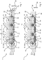
Das Piezoelement
Das Elektrodenpaar
Das Elektrodenpaar
Die Anordnung
Die Elektroden der Elektrodenpaare
Die einzelnen in
Darüber hinaus wird analog zu dem in der
Die übrigen Eigenschaften dieser Anordnung
Durch die Anordnung und Ausprägung der einzelnen Elemente der Anordnung
Über die Steuerungseinheit
Mittels der Steuerungseinheit
Gemäß einer Option kann ein hochfrequentes Umpolarisieren der Elektroden der Elektrodenpaare
Die Isolationsschicht
Die Einführung einer Lage, beispielsweise Folie mit aufgedruckten Leiterbahnen
Das Anbringen der Anordnung
Die erfindungsgemäße Anordnung
Durch eine Abstimmung der Ausrichtung der Piezoelemente
Durch die Wahl verschiedener Frequenzbereiche für die durch die Piezoelemente
Ergänzend ist darauf hinzuweisen, dass „umfassend“ keine anderen Elemente oder Schritte ausschließt und „eine“ oder „ein“ keine Vielzahl ausschließt. Ferner sei darauf hingewiesen, dass Merkmale oder Schritte, die mit Verweis auf eines der obigen Ausführungsbeispiele beschrieben worden sind, auch in Kombination mit anderen Merkmalen oder Schritten anderer oben beschriebener Ausführungsbeispiele verwendet werden können.In addition, it should be noted that "comprehensive" does not exclude other elements or steps and "one" or "one" does not exclude a large number. Furthermore, it should be pointed out that features or steps that have been described with reference to one of the above exemplary embodiments can also be used in combination with other features or steps of other exemplary embodiments described above.
Claims (15)
Priority Applications (3)
| Application Number | Priority Date | Filing Date | Title |
|---|---|---|---|
| DE102019102634.2A DE102019102634B3 (en) | 2019-02-04 | 2019-02-04 | Arrangement for mechanically changing a surface and system and aircraft with such an arrangement |
| GB2001199.5A GB2585407B (en) | 2019-02-04 | 2020-01-28 | Arrangement and system for mechanically changing a surface |
| US16/780,436 US11220328B2 (en) | 2019-02-04 | 2020-02-03 | Arrangement and system for mechanically changing a surface |
Applications Claiming Priority (1)
| Application Number | Priority Date | Filing Date | Title |
|---|---|---|---|
| DE102019102634.2A DE102019102634B3 (en) | 2019-02-04 | 2019-02-04 | Arrangement for mechanically changing a surface and system and aircraft with such an arrangement |
Publications (1)
| Publication Number | Publication Date |
|---|---|
| DE102019102634B3 true DE102019102634B3 (en) | 2020-01-09 |
Family
ID=68943978
Family Applications (1)
| Application Number | Title | Priority Date | Filing Date |
|---|---|---|---|
| DE102019102634.2A Active DE102019102634B3 (en) | 2019-02-04 | 2019-02-04 | Arrangement for mechanically changing a surface and system and aircraft with such an arrangement |
Country Status (3)
| Country | Link |
|---|---|
| US (1) | US11220328B2 (en) |
| DE (1) | DE102019102634B3 (en) |
| GB (1) | GB2585407B (en) |
Cited By (1)
| Publication number | Priority date | Publication date | Assignee | Title |
|---|---|---|---|---|
| CN112607032A (en) * | 2020-12-29 | 2021-04-06 | 重庆交通大学绿色航空技术研究院 | Device and method for realizing flow control and ice shape sensing control of aircraft |
Families Citing this family (2)
| Publication number | Priority date | Publication date | Assignee | Title |
|---|---|---|---|---|
| ES2902432T3 (en) * | 2019-04-02 | 2022-03-28 | Airbus Operations Gmbh | Panels for the cabin of an aircraft |
| CN114084342B (en) * | 2021-12-09 | 2023-12-12 | 重庆邮电大学 | Flexible deformation wing control system based on piezoelectric fiber composite material |
Citations (4)
| Publication number | Priority date | Publication date | Assignee | Title |
|---|---|---|---|---|
| US7988102B2 (en) | 2004-05-13 | 2011-08-02 | Airbus Deutschland Gmbh | Aircraft with a fluid-duct-system |
| US20110198312A1 (en) * | 2008-07-17 | 2011-08-18 | Kabushiki Kaisha Toshiba | Air current generating apparatus and method for manufacturing same |
| EP2886453A1 (en) | 2013-12-18 | 2015-06-24 | Airbus Operations GmbH | Boundary layer control system and aircraft having such a boundary layer control system |
| DE102017128478A1 (en) | 2016-11-30 | 2018-05-30 | Airbus Defence and Space GmbH | Actuators for flow control on surfaces of aerodynamic profiles |
Family Cites Families (8)
| Publication number | Priority date | Publication date | Assignee | Title |
|---|---|---|---|---|
| US20090097976A1 (en) * | 2007-10-15 | 2009-04-16 | General Electric Company | Active damping of wind turbine blades |
| WO2009053984A1 (en) * | 2007-10-26 | 2009-04-30 | Technion - Research & Development Foundation Ltd | Aerodynamic performance enhancements using discharge plasma actuators |
| JP2010192721A (en) * | 2009-02-19 | 2010-09-02 | Fujifilm Corp | Piezoelectric element and method for manufacturing the same and liquid discharger |
| DE102015213975A1 (en) * | 2015-07-23 | 2017-01-26 | Terraplasma Gmbh | Electrode assembly and plasma source for generating a non-thermal plasma and a method for operating a plasma source |
| US10155373B2 (en) * | 2015-10-16 | 2018-12-18 | Quest Integrated, Llc | Printed multifunctional skin for aerodynamic structures, and associated systems and methods |
| EP3222514B1 (en) * | 2016-03-21 | 2019-05-22 | Airbus Operations GmbH | Skin panel with an energy-storing layer for an aircraft or spacecraft and method for manufacturing an energy-storing layer for a skin panel |
| US10512150B2 (en) * | 2018-05-03 | 2019-12-17 | GM Global Technology Operations LLC | Systems and apparatuses for high performance atmosphere thin film piezoelectric resonant plasmas to modulate air flows |
| US10822042B2 (en) * | 2018-12-07 | 2020-11-03 | GM Global Technology Operations LLC | Plasma actuated drag reduction |
-
2019
- 2019-02-04 DE DE102019102634.2A patent/DE102019102634B3/en active Active
-
2020
- 2020-01-28 GB GB2001199.5A patent/GB2585407B/en active Active
- 2020-02-03 US US16/780,436 patent/US11220328B2/en not_active Expired - Fee Related
Patent Citations (4)
| Publication number | Priority date | Publication date | Assignee | Title |
|---|---|---|---|---|
| US7988102B2 (en) | 2004-05-13 | 2011-08-02 | Airbus Deutschland Gmbh | Aircraft with a fluid-duct-system |
| US20110198312A1 (en) * | 2008-07-17 | 2011-08-18 | Kabushiki Kaisha Toshiba | Air current generating apparatus and method for manufacturing same |
| EP2886453A1 (en) | 2013-12-18 | 2015-06-24 | Airbus Operations GmbH | Boundary layer control system and aircraft having such a boundary layer control system |
| DE102017128478A1 (en) | 2016-11-30 | 2018-05-30 | Airbus Defence and Space GmbH | Actuators for flow control on surfaces of aerodynamic profiles |
Cited By (1)
| Publication number | Priority date | Publication date | Assignee | Title |
|---|---|---|---|---|
| CN112607032A (en) * | 2020-12-29 | 2021-04-06 | 重庆交通大学绿色航空技术研究院 | Device and method for realizing flow control and ice shape sensing control of aircraft |
Also Published As
| Publication number | Publication date |
|---|---|
| US11220328B2 (en) | 2022-01-11 |
| US20200247531A1 (en) | 2020-08-06 |
| GB2585407B (en) | 2021-08-04 |
| GB2585407A (en) | 2021-01-13 |
| GB202001199D0 (en) | 2020-03-11 |
Similar Documents
| Publication | Publication Date | Title |
|---|---|---|
| DE102019102634B3 (en) | Arrangement for mechanically changing a surface and system and aircraft with such an arrangement | |
| EP2873617B1 (en) | Device and method for de-icing and/or avoiding ice-buildup and profiled body and aircraft equipped with such a device | |
| EP2886463B1 (en) | Actuator installation method and manufacturing method for ice protection device | |
| DE68908069T2 (en) | Fast-acting countercurrent detachment device. | |
| DE10304530B4 (en) | Deformable aerodynamic profile | |
| EP2828164B1 (en) | Device for detecting critical states of a surface | |
| EP1168463A1 (en) | Fiber composite with integrated piezoelectric actor or sensor | |
| DE102011119844A1 (en) | Composite structure with ice protection device and manufacturing process | |
| DE102010011047A1 (en) | bending transducer | |
| EP2979981B1 (en) | Lightning protection layer for fibre composite structures | |
| EP2602455A1 (en) | Wind energy assembly rotor blade with an electrical heating element | |
| DE102014210570A1 (en) | Temperature control for tempering a battery | |
| WO2009095335A2 (en) | Fiber composite part for an aircraft or spacecraft | |
| EP3244692A1 (en) | Electrically heatable layer stack | |
| DE102018004814A1 (en) | Heated leading edge device, leading edge heating system and aircraft with it | |
| EP3020638A1 (en) | Device and method for de-icing and/or avoiding ice-buildup and profiled body and aircraft equipped with such a device | |
| EP2462023B1 (en) | Device for deicing airplanes | |
| DE102004060675B4 (en) | De-icing of aircraft | |
| DE102017128478B4 (en) | Actuators for flow control on surfaces of aerodynamic profiles | |
| DE202011104749U1 (en) | Multilayer surface heating system | |
| DE102014200443B4 (en) | Sensor element for determining strains | |
| DE102021129229B9 (en) | Piezoelectric transducer | |
| DE102006037900B4 (en) | Arrangement for signal transmission in a structural component made of carbon fiber reinforced plastic (CFRP) | |
| EP1235284B1 (en) | Piezoceramic plate and method of manufacturing the same | |
| DE102019003326A1 (en) | Flow surface of a vehicle with a de-icing device for removing or preventing the formation of ice on the flow surface |
Legal Events
| Date | Code | Title | Description |
|---|---|---|---|
| R012 | Request for examination validly filed | ||
| R016 | Response to examination communication | ||
| R018 | Grant decision by examination section/examining division | ||
| R020 | Patent grant now final | ||
| R079 | Amendment of ipc main class |
Free format text: PREVIOUS MAIN CLASS: H01L0041090000 Ipc: H10N0030200000 |