DE102018207605B9 - MEMS sensor, MEMS sensor system and method for producing a MEMS sensor system - Google Patents
MEMS sensor, MEMS sensor system and method for producing a MEMS sensor system Download PDFInfo
- Publication number
- DE102018207605B9 DE102018207605B9 DE102018207605.7A DE102018207605A DE102018207605B9 DE 102018207605 B9 DE102018207605 B9 DE 102018207605B9 DE 102018207605 A DE102018207605 A DE 102018207605A DE 102018207605 B9 DE102018207605 B9 DE 102018207605B9
- Authority
- DE
- Germany
- Prior art keywords
- mems sensor
- volume
- membrane
- opening
- housing
- Prior art date
- Legal status (The legal status is an assumption and is not a legal conclusion. Google has not performed a legal analysis and makes no representation as to the accuracy of the status listed.)
- Active
Links
Images




Classifications
-
- B—PERFORMING OPERATIONS; TRANSPORTING
- B81—MICROSTRUCTURAL TECHNOLOGY
- B81B—MICROSTRUCTURAL DEVICES OR SYSTEMS, e.g. MICROMECHANICAL DEVICES
- B81B7/00—Microstructural systems ; Auxiliary parts of microstructural devices or systems
- B81B7/0032—Packages or encapsulation
- B81B7/0061—Packages or encapsulation suitable for fluid transfer from the MEMS out of the package or vice versa, e.g. transfer of liquid, gas, sound
-
- B—PERFORMING OPERATIONS; TRANSPORTING
- B81—MICROSTRUCTURAL TECHNOLOGY
- B81B—MICROSTRUCTURAL DEVICES OR SYSTEMS, e.g. MICROMECHANICAL DEVICES
- B81B7/00—Microstructural systems ; Auxiliary parts of microstructural devices or systems
- B81B7/0032—Packages or encapsulation
-
- B—PERFORMING OPERATIONS; TRANSPORTING
- B81—MICROSTRUCTURAL TECHNOLOGY
- B81B—MICROSTRUCTURAL DEVICES OR SYSTEMS, e.g. MICROMECHANICAL DEVICES
- B81B7/00—Microstructural systems ; Auxiliary parts of microstructural devices or systems
- B81B7/0009—Structural features, others than packages, for protecting a device against environmental influences
-
- B—PERFORMING OPERATIONS; TRANSPORTING
- B81—MICROSTRUCTURAL TECHNOLOGY
- B81B—MICROSTRUCTURAL DEVICES OR SYSTEMS, e.g. MICROMECHANICAL DEVICES
- B81B3/00—Devices comprising flexible or deformable elements, e.g. comprising elastic tongues or membranes
- B81B3/0018—Structures acting upon the moving or flexible element for transforming energy into mechanical movement or vice versa, i.e. actuators, sensors, generators
- B81B3/0021—Transducers for transforming electrical into mechanical energy or vice versa
-
- B—PERFORMING OPERATIONS; TRANSPORTING
- B81—MICROSTRUCTURAL TECHNOLOGY
- B81B—MICROSTRUCTURAL DEVICES OR SYSTEMS, e.g. MICROMECHANICAL DEVICES
- B81B7/00—Microstructural systems ; Auxiliary parts of microstructural devices or systems
- B81B7/02—Microstructural systems ; Auxiliary parts of microstructural devices or systems containing distinct electrical or optical devices of particular relevance for their function, e.g. microelectro-mechanical systems [MEMS]
-
- B—PERFORMING OPERATIONS; TRANSPORTING
- B81—MICROSTRUCTURAL TECHNOLOGY
- B81C—PROCESSES OR APPARATUS SPECIALLY ADAPTED FOR THE MANUFACTURE OR TREATMENT OF MICROSTRUCTURAL DEVICES OR SYSTEMS
- B81C1/00—Manufacture or treatment of devices or systems in or on a substrate
- B81C1/00015—Manufacture or treatment of devices or systems in or on a substrate for manufacturing microsystems
- B81C1/00134—Manufacture or treatment of devices or systems in or on a substrate for manufacturing microsystems comprising flexible or deformable structures
- B81C1/00158—Diaphragms, membranes
-
- B—PERFORMING OPERATIONS; TRANSPORTING
- B81—MICROSTRUCTURAL TECHNOLOGY
- B81C—PROCESSES OR APPARATUS SPECIALLY ADAPTED FOR THE MANUFACTURE OR TREATMENT OF MICROSTRUCTURAL DEVICES OR SYSTEMS
- B81C1/00—Manufacture or treatment of devices or systems in or on a substrate
- B81C1/00015—Manufacture or treatment of devices or systems in or on a substrate for manufacturing microsystems
- B81C1/00261—Processes for packaging MEMS devices
- B81C1/00309—Processes for packaging MEMS devices suitable for fluid transfer from the MEMS out of the package or vice versa, e.g. transfer of liquid, gas, sound
-
- G—PHYSICS
- G01—MEASURING; TESTING
- G01L—MEASURING FORCE, STRESS, TORQUE, WORK, MECHANICAL POWER, MECHANICAL EFFICIENCY, OR FLUID PRESSURE
- G01L9/00—Measuring steady of quasi-steady pressure of fluid or fluent solid material by electric or magnetic pressure-sensitive elements; Transmitting or indicating the displacement of mechanical pressure-sensitive elements, used to measure the steady or quasi-steady pressure of a fluid or fluent solid material, by electric or magnetic means
- G01L9/0041—Transmitting or indicating the displacement of flexible diaphragms
-
- G—PHYSICS
- G01—MEASURING; TESTING
- G01N—INVESTIGATING OR ANALYSING MATERIALS BY DETERMINING THEIR CHEMICAL OR PHYSICAL PROPERTIES
- G01N29/00—Investigating or analysing materials by the use of ultrasonic, sonic or infrasonic waves; Visualisation of the interior of objects by transmitting ultrasonic or sonic waves through the object
- G01N29/22—Details, e.g. general constructional or apparatus details
- G01N29/24—Probes
- G01N29/2418—Probes using optoacoustic interaction with the material, e.g. laser radiation, photoacoustics
- G01N29/2425—Probes using optoacoustic interaction with the material, e.g. laser radiation, photoacoustics optoacoustic fluid cells therefor
-
- H—ELECTRICITY
- H04—ELECTRIC COMMUNICATION TECHNIQUE
- H04R—LOUDSPEAKERS, MICROPHONES, GRAMOPHONE PICK-UPS OR LIKE ACOUSTIC ELECTROMECHANICAL TRANSDUCERS; ELECTRIC HEARING AIDS; PUBLIC ADDRESS SYSTEMS
- H04R19/00—Electrostatic transducers
- H04R19/005—Electrostatic transducers using semiconductor materials
-
- H—ELECTRICITY
- H04—ELECTRIC COMMUNICATION TECHNIQUE
- H04R—LOUDSPEAKERS, MICROPHONES, GRAMOPHONE PICK-UPS OR LIKE ACOUSTIC ELECTROMECHANICAL TRANSDUCERS; ELECTRIC HEARING AIDS; PUBLIC ADDRESS SYSTEMS
- H04R19/00—Electrostatic transducers
- H04R19/04—Microphones
-
- B—PERFORMING OPERATIONS; TRANSPORTING
- B81—MICROSTRUCTURAL TECHNOLOGY
- B81B—MICROSTRUCTURAL DEVICES OR SYSTEMS, e.g. MICROMECHANICAL DEVICES
- B81B2201/00—Specific applications of microelectromechanical systems
- B81B2201/02—Sensors
- B81B2201/0214—Biosensors; Chemical sensors
-
- B—PERFORMING OPERATIONS; TRANSPORTING
- B81—MICROSTRUCTURAL TECHNOLOGY
- B81B—MICROSTRUCTURAL DEVICES OR SYSTEMS, e.g. MICROMECHANICAL DEVICES
- B81B2201/00—Specific applications of microelectromechanical systems
- B81B2201/02—Sensors
- B81B2201/0257—Microphones or microspeakers
-
- B—PERFORMING OPERATIONS; TRANSPORTING
- B81—MICROSTRUCTURAL TECHNOLOGY
- B81B—MICROSTRUCTURAL DEVICES OR SYSTEMS, e.g. MICROMECHANICAL DEVICES
- B81B2201/00—Specific applications of microelectromechanical systems
- B81B2201/02—Sensors
- B81B2201/0264—Pressure sensors
-
- B—PERFORMING OPERATIONS; TRANSPORTING
- B81—MICROSTRUCTURAL TECHNOLOGY
- B81B—MICROSTRUCTURAL DEVICES OR SYSTEMS, e.g. MICROMECHANICAL DEVICES
- B81B2203/00—Basic microelectromechanical structures
- B81B2203/01—Suspended structures, i.e. structures allowing a movement
- B81B2203/0127—Diaphragms, i.e. structures separating two media that can control the passage from one medium to another; Membranes, i.e. diaphragms with filtering function
-
- B—PERFORMING OPERATIONS; TRANSPORTING
- B81—MICROSTRUCTURAL TECHNOLOGY
- B81B—MICROSTRUCTURAL DEVICES OR SYSTEMS, e.g. MICROMECHANICAL DEVICES
- B81B2207/00—Microstructural systems or auxiliary parts thereof
- B81B2207/01—Microstructural systems or auxiliary parts thereof comprising a micromechanical device connected to control or processing electronics, i.e. Smart-MEMS
- B81B2207/012—Microstructural systems or auxiliary parts thereof comprising a micromechanical device connected to control or processing electronics, i.e. Smart-MEMS the micromechanical device and the control or processing electronics being separate parts in the same package
-
- B—PERFORMING OPERATIONS; TRANSPORTING
- B81—MICROSTRUCTURAL TECHNOLOGY
- B81B—MICROSTRUCTURAL DEVICES OR SYSTEMS, e.g. MICROMECHANICAL DEVICES
- B81B2207/00—Microstructural systems or auxiliary parts thereof
- B81B2207/09—Packages
-
- G—PHYSICS
- G01—MEASURING; TESTING
- G01N—INVESTIGATING OR ANALYSING MATERIALS BY DETERMINING THEIR CHEMICAL OR PHYSICAL PROPERTIES
- G01N2291/00—Indexing codes associated with group G01N29/00
- G01N2291/02—Indexing codes associated with the analysed material
- G01N2291/021—Gases
-
- H—ELECTRICITY
- H04—ELECTRIC COMMUNICATION TECHNIQUE
- H04R—LOUDSPEAKERS, MICROPHONES, GRAMOPHONE PICK-UPS OR LIKE ACOUSTIC ELECTROMECHANICAL TRANSDUCERS; ELECTRIC HEARING AIDS; PUBLIC ADDRESS SYSTEMS
- H04R2201/00—Details of transducers, loudspeakers or microphones covered by H04R1/00 but not provided for in any of its subgroups
- H04R2201/003—Mems transducers or their use
Landscapes
- Engineering & Computer Science (AREA)
- Microelectronics & Electronic Packaging (AREA)
- Physics & Mathematics (AREA)
- Computer Hardware Design (AREA)
- Acoustics & Sound (AREA)
- Signal Processing (AREA)
- Manufacturing & Machinery (AREA)
- Chemical & Material Sciences (AREA)
- Analytical Chemistry (AREA)
- General Health & Medical Sciences (AREA)
- Health & Medical Sciences (AREA)
- General Physics & Mathematics (AREA)
- Immunology (AREA)
- Biochemistry (AREA)
- Pathology (AREA)
- Life Sciences & Earth Sciences (AREA)
- Optics & Photonics (AREA)
- Toxicology (AREA)
- Micromachines (AREA)
- Electrostatic, Electromagnetic, Magneto- Strictive, And Variable-Resistance Transducers (AREA)
- Pressure Sensors (AREA)
Abstract
MEMS-Sensorsystem mit:
einem Systemgehäuse (34), das ein Systemvolumen (38) aufweist; und
einem MEMS-Sensor mit:
einem Sensorgehäuse (12);
einer Membran (14), die in dem Sensorgehäuse (12) angeordnet ist, wobei ein erstes Teilvolumen (16) des Sensorgehäuses (12) an einer ersten Hauptseite (221) der Membran (14) angrenzt und ein zweites Teilvolumen (18) des Sensorgehäuses (12) an einer zweiten Hauptseite (222) der Membran (14) angrenzt, wobei die zweite Hauptseite (222) der ersten Hauptseite (221) gegenüberliegend angeordnet ist;
einer ersten Öffnung (241) in dem Sensorgehäuse (12), die an das erste Teilvolumen (16) angrenzt;
einer zweiten Öffnung (242) in dem Sensorgehäuse (12), die das zweite Teilvolumen (18) akustisch transparent mit einer äußeren Umgebung des Sensorgehäuses (12) verbindet; und
einem elastischen Element (44),
das in der ersten Öffnung (241) angeordnet ist und ausgebildet ist, um basierend auf einem Fluiddruck (P) in der äußeren Umgebung des Sensorgehäuses einen Inhalt des ersten Teilvolumens (16) zu verändern;
wobei das MEMS-Sensorsystem so ausgestaltet ist, dass das Systemvolumen (38) über die erste Öffnung (241) gekoppelt ist, wobei der MEMS-Sensor über die zweite Öffnung (242) mit einer Umgebung (26) des MEMS-Sensorsystems fluidisch gekoppelt ist;
wobei das Systemvolumen eine Resonanzfrequenz der Membran (14) für einen Fluidschall in der Umgebung des MEMS-Sensorsystem einstellt.

a system housing (34) having a system volume (38); and
a MEMS sensor with:
a sensor housing (12);
a membrane (14) arranged in the sensor housing (12), wherein a first partial volume (16) of the sensor housing (12) adjoins a first main side (22 1 ) of the membrane (14) and a second partial volume (18) of the sensor housing (12) adjoins a second main side (22 2 ) of the membrane (14), wherein the second main side (22 2 ) is arranged opposite the first main side (22 1 );
a first opening (24 1 ) in the sensor housing (12) adjacent to the first partial volume (16);
a second opening (24 2 ) in the sensor housing (12) which connects the second partial volume (18) in an acoustically transparent manner with an external environment of the sensor housing (12); and
an elastic element (44),
which is arranged in the first opening (24 1 ) and is designed to change a content of the first partial volume (16) based on a fluid pressure (P) in the external environment of the sensor housing;
wherein the MEMS sensor system is designed such that the system volume (38) is coupled via the first opening (24 1 ), wherein the MEMS sensor is fluidically coupled to an environment (26) of the MEMS sensor system via the second opening (24 2 );
wherein the system volume sets a resonance frequency of the membrane (14) for a fluid sound in the environment of the MEMS sensor system.
Description
Die vorliegende Offenbarung bezieht sich auf einen MEMS-Sensor, beispielsweise ein MEMS-Mikrofon oder einen Drucksensor, auf ein MEMS-Sensorsystem und auf ein Verfahren zum Bereitstellen eines MEMS-Sensorsystems. Die vorliegende Offenbarung bezieht sich ferner auf ein MEMS-Mikrofon mit zwei Schalleintrittsöffnungen (Dual Port Microphone).The present disclosure relates to a MEMS sensor, for example a MEMS microphone or a pressure sensor, to a MEMS sensor system and to a method for providing a MEMS sensor system. The present disclosure further relates to a MEMS microphone with two sound inlet openings (dual port microphone).
Membrane aufweisende mikroelektromechanische Systeme (MEMS) können in Siliziumtechnologie hergestellt sein und können eine auf der Auslenkung der Membran basierte Funktionalität aufweisen. Beispiele für solche MEMS sind MEMS-Mikrofone und/oder MEMS-Lautsprecher, die basierend auf einem inversen Betrieb ein elektrisches Signal in einen Schalldruck überführen (Lautsprecher) oder eine Variation im Schalldruck in ein elektrisches Signal überführen (Mikrofone). Auf dem Prinzip der Überführung eines Schalldrucks in eine elektrisches Signal basieren auch Drucksensoren, die ebenfalls als MEMS ausführbar sind.Microelectromechanical systems (MEMS) with membranes can be manufactured using silicon technology and can have a functionality based on the deflection of the membrane. Examples of such MEMS are MEMS microphones and/or MEMS loudspeakers, which convert an electrical signal into a sound pressure based on an inverse operation (loudspeakers) or convert a variation in the sound pressure into an electrical signal (microphones). Pressure sensors, which can also be implemented as MEMS, are also based on the principle of converting a sound pressure into an electrical signal.
In
In
In
In
In
In
In
In
In
In
Wünschenswert wären MEMS-Sensoren, MEMS-Sensorsysteme und ein Verfahren zum Herstellen eines MEMS-Sensorsystems, die eine hohe Vielfalt bezüglich der Vorrichtung oder Systeme, in welchen der spätere MEMS-Sensor eingesetzt wird, aufweisen.It would be desirable to have MEMS sensors, MEMS sensor systems and a method for producing a MEMS sensor system that have a high degree of diversity with regard to the device or systems in which the subsequent MEMS sensor is used.
Beispiele schaffen einen MEMS-Sensor mit einem Sensorgehäuse, einer Membran, die in dem Sensorgehäuse angeordnet ist, wobei ein erstes Teilvolumen des Sensorgehäuses an einer ersten Hauptseite der Membran angrenzt und ein zweites Teilvolumen des Sensorgehäuses an einer zweiten Hauptseite der Membran angrenzt, wobei die zweite Hauptseite der ersten Hauptseite gegenüberliegend angeordnet ist. Der MEMS-Sensor umfasst eine erste Öffnung in dem Sensorgehäuse, die das erste Teilvolumen mit einer äußeren Umgebung des Sensorgehäuses akustisch verbindet. Der MEMS-Sensor umfasst eine zweite Öffnung in dem Sensorgehäuse, die das zweite Teilvolumen mit der äußeren Umgebung des Sensorgehäuses akustisch verbindet. Dies ermöglicht den Einsatz des MEMS-Sensors in unterschiedlichen Systemen bei gleicher oder vergleichbarer Auslegung der Einzelkomponenten. So kann beispielsweise ein Back Volume (rückseitiges Volumen) unterschiedlich ausgestaltet werden, um den Frequenzgang der Membran zu beeinflussen oder einzustellen, so dass ein identisches MEMS-Modul in unterschiedlichen Systemen (Back Volumes) unterschiedliche Eigenschaften zeigt und deshalb flexibel einsetzbar ist.Examples provide a MEMS sensor with a sensor housing, a membrane arranged in the sensor housing, wherein a first partial volume of the sensor housing adjoins a first main side of the membrane and a second partial volume of the sensor housing adjoins a second main side of the membrane, wherein the second main side is arranged opposite the first main side. The MEMS sensor comprises a first opening in the sensor housing, which acoustically connects the first partial volume with an external environment of the sensor housing. The MEMS sensor comprises a second opening in the sensor housing, which acoustically connects the second partial volume with the external environment of the sensor housing. This enables the MEMS sensor to be used in different systems with the same or comparable design of the individual components. For example, a back volume can be designed differently in order to influence or adjust the frequency response of the membrane, so that an identical MEMS module shows different properties in different systems (back volumes) and can therefore be used flexibly.
Gemäß einem Beispiel umfasst ein MEMS-Sensor ein Sensorgehäuse und eine Membran, die in dem Sensorgehäuse angeordnet ist. Ein erstes Teilvolumen des Sensorgehäuses grenzt an einer ersten Hauptseite der Membran an und ein zweites Teilvolumen des Sensorgehäuses grenzt an einer zweiten Hauptseite der Membran an. Die zweite Hauptseite ist der ersten Hauptseite gegenüberliegend angeordnet. Eine erste Öffnung in dem Sensorgehäuse akustisch transparent verbindet das erste Teilvolumen mit einer äußeren Umgebung des Sensorgehäuses. Eine zweite Öffnung in dem Sensorgehäuse grenzt an das zweite Teilvolumen an. Der MEMS-Sensor umfasst ein elastisches Element, das in der zweiten Öffnung angeordnet ist und ausgebildet ist, um basierend auf einem Fluiddruck in der äußeren Umgebung einen Inhalt des zweiten Teilvolumens zu verändern. Dies ermöglicht eine Einstellung eines Drucks in dem zweiten Teilvolumen durch Auslenkung des flexiblen Elements und so eine Einstellung des Frequenzgangs der Membran, so dass auch dieser MEMS-Sensor flexibel einsetzbar ist.According to one example, a MEMS sensor comprises a sensor housing and a membrane arranged in the sensor housing. A first partial volume of the sensor housing adjoins a first main side of the membrane and a second partial volume of the sensor housing adjoins a second main side of the membrane. The second main side is arranged opposite the first main side. A first opening in the sensor housing acoustically transparently connects the first partial volume to an external environment of the sensor housing. A second opening in the sensor housing adjoins the second partial volume. The MEMS sensor comprises an elastic element arranged in the second opening and designed to change a content of the second partial volume based on a fluid pressure in the external environment. This enables a pressure in the second partial volume to be adjusted by deflecting the flexible element and thus an adjustment of the frequency response of the membrane, so that this MEMS sensor can also be used flexibly.
Ausführungsbeispiele schaffen ein MEMS-Sensorsystem gemäß Anspruch 1 und gemäß Anspruch 9 sowie ein Verfahren gemäß Anspruch 10Embodiments provide a MEMS sensor system according to claim 1 and claim 9 and a method according to
Ausführungsbeispiele werden nachfolgend Bezug nehmend auf die beiliegenden Zeichnungen erläutert. Es zeigen:
-
1 eine schematische Seitenschnittansicht eines MEMS-Sensors gemäß einem Ausführungsbeispiel: -
2 eine schematische Seitenschnittansicht eines MEMS-Sensors gemäß einem Ausführungsbeispiel, mit einem mehrteiligen MEMS-Gehäuse; -
3 eine schematische perspektivische Ansicht eines MEMS-Sensorsystems gemäß einem Ausführungsbeispiel; -
4 eine schematische Seitenschnittansicht eines MEMS-Sensorsystems gemäß einem Ausführungsbeispiel mit einem mehrteiligen Gehäuse; -
5 eine schematische Seitenschnittansicht eines MEMS-Sensorsystems, bei dem ein akustisch transparentes Material in einer Öffnung angeordnet ist; -
6 eine schematische Seitenschnittansicht eines MEMS-Sensorsystems gemäß einem weiteren Ausführungsbeispiel, das einen MEMS-Sensor gemäß einem Ausführungsbeispiel umfasst, bei dem ein Systemvolumen auf einer anderen Seite angeordnet ist als in5 ; -
7 eine schematische Seitenschnittansicht eines MEMS-Sensorsystems, das einen MEMS-Sensor gemäß einem Ausführungsbeispiel aufweist, der verglichen mit dem MEMS-Sensor aus6 das akustisch transparente Material in der Öffnung aufweist; -
8a eine schematischen Seitenschnittansicht von Druckverläufen in einem MEMS-Sensorsystem gemäß einem Ausführungsbeispiel; -
8b eine schematische Seitenschnittansicht des MEMS-Sensorsystems aus8a , bei dem die Geschwindigkeit des Fluids in dem Teilvolumen dargestellt ist; -
8c eine schematische Seitenschnittansicht des MEMS-Sensorsystems aus8a , bei dem eine Erwärmung der Gehäusestrukturen dargestellt ist; -
9a einen schematischen Frequenzgang eines Bottom-Port-Mikrofons -
9b einen schematischen Frequenzgang eines MEMS-Sensors gemäß einem Ausführungsbeispiel; -
10 eine schematische Seitenschnittansicht eines MEMS-Sensors gemäß einem Ausführungsbeispiel beschrieben mit einem elastischen Element in einer Öffnung zwischen einem Teilvolumen und einem Systemvolumen; -
11 eine schematische Seitenschnittansicht eines MEMS-Sensorsystems gemäß einem Ausführungsbeispiel, bei dem der MEMS-Sensor aus10 in dem Systemgehäuse angeordnet ist; und -
12 ein schematisches Ablaufdiagramm eines Verfahrens gemäß einem Ausführungsbeispiel.
-
1 a schematic side sectional view of a MEMS sensor according to an embodiment: -
2 a schematic side sectional view of a MEMS sensor according to an embodiment, with a multi-part MEMS housing; -
3 a schematic perspective view of a MEMS sensor system according to an embodiment; -
4 a schematic side sectional view of a MEMS sensor system according to an embodiment with a multi-part housing; -
5 a schematic side sectional view of a MEMS sensor system in which an acoustically transparent material is arranged in an opening; -
6 a schematic side sectional view of a MEMS sensor system according to another embodiment, which comprises a MEMS sensor according to an embodiment in which a system volume is arranged on a different side than in5 ; -
7 a schematic side sectional view of a MEMS sensor system comprising a MEMS sensor according to an embodiment, which compared with the MEMS sensor of6 which has acoustically transparent material in the opening; -
8a a schematic side sectional view of pressure curves in a MEMS sensor system according to an embodiment; -
8b a schematic side sectional view of the MEMS sensor system8a , where the velocity of the fluid in the partial volume is represented; -
8c a schematic side sectional view of the MEMS sensor system8a , which shows heating of the housing structures; -
9a a schematic frequency response of a bottom port microphone -
9b a schematic frequency response of a MEMS sensor according to an embodiment; -
10 a schematic side sectional view of a MEMS sensor according to an embodiment described with an elastic element in an opening between a partial volume and a system volume; -
11 a schematic side sectional view of a MEMS sensor system according to an embodiment in which the MEMS sensor consists of10 is arranged in the system housing; and -
12 a schematic flow diagram of a method according to an embodiment.
Bevor nachfolgend Ausführungsbeispiele im Detail anhand der Zeichnungen näher erläutert werden, wird darauf hingewiesen, dass identische, funktionsgleiche oder gleichwirkende Elemente, Objekte und/oder Strukturen in den unterschiedlichen Figuren mit den gleichen Bezugszeichen versehen sind, so dass die in den unterschiedlichen Ausführungsbeispielen dargestellte Beschreibung dieser Elemente austauschbar ist bzw. aufeinander angewendet werden kann.Before the following embodiments are explained in detail with reference to the drawings, it is pointed out that identical, functionally equivalent or equivalent elements, objects and/or structures in the different figures are provided with the same reference numerals, so that the description of these elements shown in the different embodiments is interchangeable or can be applied to one another.
Nachfolgende Ausführungen beziehen sich auf MEMS-Sensoren, auf MEMS-Sensorsysteme und auf ein Verfahren zum Herstellen eines MEMS-Sensors. Die nachfolgenden Ausführungen beziehen sich dabei insbesondere auf MEMS-Sensoren und mikroelektromechanische Systeme, bei denen die Bewegung oder Auslenkung einer Membran mittels eines elektrischen Signals erfasst wird und/oder basierend auf dem elektrischen Signal eine Bewegung oder Auslenkung der Membran angeregt wird. Obwohl die nachfolgenden Ausführungen auf MEMS-Sensoren, etwa Mikrofone oder Drucksensoren, gerichtet sind, können die speziellen Ausgestaltungen, die im Zusammenhang hiermit beschrieben werden, auch für MEMS-Lautsprecher angewendet werden. Alternativ oder zusätzlich zur Verwendung als Schallwandler bzw. Mikrofon können die MEMS-Sensoren auch als Drucksensoren verwendet werden, beispielsweise als Differenzdrucksensor, bei dem unterschiedliche Drücke durch die unterschiedlichen Öffnungen (Ports) an der Membran 14 wirken.The following statements relate to MEMS sensors, MEMS sensor systems and a method for producing a MEMS sensor. The following statements relate in particular to MEMS sensors and microelectromechanical systems in which the movement or deflection of a membrane is detected by means of an electrical signal and/or a movement or deflection of the membrane is stimulated based on the electrical signal. Although the following statements are directed at MEMS sensors, such as microphones or pressure sensors, the special designs described in connection with this can also be used for MEMS loudspeakers. Alternatively or in addition to use as a sound transducer or microphone, the MEMS sensors can also be used as pressure sensors, for example as a differential pressure sensor in which different pressures act through the different openings (ports) on the
MEMS können beispielsweise in Siliziumtechnologie hergestellt werden, etwa durch Bereitstellen oder Erzeugen eines Schichtstapels mit einem oder mehreren Halbleitern, wobei auch Dotierungen derselben und/oder die Verwendung anderer Materialien wie elektrisch isolierende Materialien und/oder metallischer Materialien möglich ist.MEMS can be manufactured using silicon technology, for example by providing or creating a layer stack with one or more semiconductors, whereby doping of the same and/or the use of other materials such as electrically insulating materials and/or metallic materials is also possible.
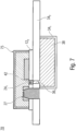
Das Sensorgehäuse 12 weist eine erste Öffnung 241 und eine zweite Öffnung 242 auf, wobei durch die Öffnung 241 das erste Teilvolumen 16 mit einer äußeren Umgebung 26 des MEMS-Sensors akustisch transparent verbunden ist. Durch die Öffnung 242 ist das zweite Teilvolumen 18 akustisch transparent mit der äußeren Umgebung 26 verbunden und/oder fluidisch gekoppelt. Gemäß einem Ausführungsbeispiel sind die Öffnungen 241 und 242 unverschlossene und unblockierte Öffnungen in dem Sensorgehäuse 12. Weitere Ausführungsbeispiele schaffen MEMS-Sensoren, bei denen ein akustisch transparentes Material in der ersten und/oder zweiten Öffnung angeordnet ist, wobei akustisch transparent so zu verstehen ist, dass eine Schalldämpfung von höchstens 3 dB(A), höchstens 2,5 dB(A) oder höchstens 2 dB(A) erhalten wird.The
Der MEMS-Sensor kann gemäß einer Möglichkeit seiner Verwendung so eingesetzt werden, dass er einen Druck oder eine Druckvariation in dem ersten Teilvolumen 16 oder dem zweiten Teilvolumen 18 detektiert, indem der Druck oder die Druckvariation zu einer Auslenkung der Membran 14 führt. Insbesondere im Bereich der dynamischen Auslenkung, etwa zur Schallerfassung oder in der Verwendung im Rahmen fotoakustischer Sensoren kann die Empfindlichkeit und/oder der Frequenzgang der Membran 14 durch einen Druck und/oder eine Größe in dem gegenüberliegenden Teilvolumen 18 bzw. 16 beeinflusst oder bestimmt sein. Die fluidische und akustisch transparente Kopplung dieses als Back Volume verwendeten Teilvolumens mit der äußeren Umgebung kann es ermöglichen, den MEMS-Sensor 10 in einem Systemgehäuse einzusetzen, dessen inneres Volumen dann das Back Volume mit beeinflusst, so dass der resultierende Frequenzgang der Membran 14 inklusive einer entsprechenden Eckfrequenz durch das Systemvolumen bestimmt ist. Dies ermöglicht es, die Frequenzeigenschaften des MEMS-Sensors 10 basierend auf dem Systemgehäuse einzustellen, so dass eine applikationsspezifische Anpassung an unterschiedliche Systemgehäuse vereinfacht ist oder ganz entfallen kann.According to one possible use, the MEMS sensor can be used to detect a pressure or a pressure variation in the first
Der möglicherweise zwischen dem ersten Teilvolumen 16 und dem zweiten Teilvolumen 18 bestehende akustische Kurzschluss kann in einer späteren Verwendung durch Einbau in einem Systemgehäuse behoben oder beseitigt werden, indem das Systemgehäuse eine Trennung zwischen dem Außenbereich, der mit der Membran 14 fluidisch gekoppelt ist und dem Inneren des Systemvolumens vornimmt.The acoustic short circuit that may exist between the first
Die Membran 14 kann ein oder mehrere Lüftungslöcher (Ventilation Holes) 32 aufweisen, die eine fluidische Kopplung zwischen den Teilvolumina 16 und 18 bereitstellen, wobei dies jedoch unter Einwirkung eines fluidischen Widerstands erfolgt, das bedeutet, die Belüftungsöffnungen 32 sind akustisch zumindest teilweise intransparent, so dass eine Druckvariation in dem Teilvolumen 16 oder 18 zu einer Auslenkung der Membran 14 führt. Ventilation Holes 32 in der Membran 14 können zum Druckausgleich zwischen den Seiten der Membran 14 genutzt werden. Obwohl die Membranöffnung das erste Teilvolumen 16 und das zweite Teilvolumen 18 miteinander fluidisch koppelt, kann diese Kopplung akustisch zumindest teilweise intransparent sein. Beispielsweise kann die Kopplung durch die Membranöffnung als Tiefpass für eine Druckänderung in dem Teilvolumen 16 und/oder 18 wirken.The
Das beschriebene Systemvolumen 38 kann hierbei genutzt werden, um den entsprechenden Referenzdruck einzustellen und gegebenenfalls zu verändern. Das bedeutet, über das Systemvolumen kann ein veränderlicher Druck an die Membran 14 anlegbar sein, etwa über das Teilvolumen 16.The
Obwohl die MEMS-Sensorsysteme 30 und 40 so beschrieben sind, dass sie den MEMS-Sensor 20 umfassen, kann alternativ oder zusätzlich auch der MEMS-Sensor 10 angeordnet sein.Although the
Beeinflusst von der Anordnung des MEMS-Sensors 20 in dem Systemvolumen 34 kann das Teilvolumen 18 eine Druckzugangsöffnung oder Schallzugangsöffnung (Sound Port) bereitstellen, der beispielsweise als Bottom Sound Port (unterer Sound Port) bezeichnet wird. Demgegenüber kann die Öffnung 241 als Top Sound Port (oberer Sound Port) bezeichnet werden, wobei die Begriffe „unten/oben“ beliebig änderbar oder vertauschbar sind. Influenced by the arrangement of the
Eine elektronische Datenverarbeitung des MEMS-Sensorsystems 40 kann dabei auf einem elektrisch erfassten Auslenksignal beruhen, welches die Auslenkung der Membran 14 wiedergibt und welches von der ASIC 28 empfangen werden kann. Die ASIC 28 kann eine Vorverarbeitung des Auslenksignals ausführen und ein vorverarbeitetes Auslenksignal über die Schaltungsstrukturen des Gehäuseteils 122 bereitstellen, welche unverarbeitet oder weiterverarbeitet über Schaltungsstrukturen des Gehäuseteils 342 als Sensorsignal dem MEMS-Sensorsystem 40 bereitgestellt werden. Das bedeutet, dass das MEMS-Sensorsystem eine Ausleseschaltung in Form der Schaltung 122 aufweisen kann, die konfiguriert ist, um ein verarbeitetes Auslenksignal, das mit der Auslenkung der Membran 14 korreliert, und das beispielsweise von der ASIC 28 erhalten wird, zu erhalten und/oder bereitzustellen. Das MEMS-Sensorsystem weist eine Systemschaltung auf, die beispielsweise in der kundenseitigen Schaltung des Systemgehäuses, etwa in dem Gehäuseteil 342 integriert sein kann, und die mit der Ausleseschaltung, das bedeutet, mit Schaltungsstrukturen des Gehäuseteils 122, elektrisch verbunden ist.Electronic data processing of the
Das bedeutet, dass ein MEMS-Sensor gemäß hierin beschriebenen Ausführungsbeispielen eine Ausleseschaltung aufweisen kann, die konfiguriert ist, um ein verarbeitetes Auslenksignal, das auf eine Auslenkung der Membran 14 basiert, zu erhalten, etwa indem ein entsprechendes Signal von der ASIC zu Schaltungsstrukturen in dem Gehäuseteil 122 geleitet werden. Ferner kann der MEMS-Sensor ausgebildet sein, um ein Sensorsignal bereitzustellen, wobei die Ausleseschaltung mit einer Systemschaltung elektrisch verbindbar ist. Die Systemschaltung kann beispielsweise zumindest teilweise als Schaltungsstrukturen in dem Gehäuseteil 342 gebildet sein.This means that a MEMS sensor according to embodiments described herein may have a readout circuit configured to obtain a processed deflection signal based on a deflection of the
Das akustisch transparente Material 42 kann akustisch gekoppelt sein, das bedeutet, es kann sich in einem akustisch relevanten Bereich des MEMS-Sensorsystems 50 oder des MEMS-Sensors 55 befinden. Dies wird beispielsweise dadurch erreicht, dass das akustisch transparente Material 42 das Teilvolumen 16 mit der Volumenerweiterung, d. h., das Systemvolumen 38 fluidisch koppelt und/oder dass das akustisch transparente Material 42 das Volumen 422 mit der äußeren Umgebung 26 fluidisch koppelt.The acoustically
Das akustisch transparente Material 42 kann beispielsweise porös gebildet sein und so eine mechanische Barriere für Nässe, Feuchte und/oder Partikel bereitstellen, während eine geringe oder vernachlässigbare akustische Beeinflussung des MEMS erhalten wird. Alternativ kann auch eine vorgegebene Beeinflussung erfolgen, so dass basierend auf dem akustisch transparenten Material eine akustische Anpassung zusätzlich zum mechanischen Schutz erhalten wird. Das bedeutet, obwohl das akustisch transparente Material 42 bevorzugt einen geringen Einfluss auf die akustische Kopplung zwischen dem Teilvolumen 16 und dem Systemvolumen 38 bewirkt, kann gemäß anderen bevorzugten Ausführungsformen auch eine Einstellung einer akustischen Kopplung zwischen dem benachbarten Teilvolumen und der äußeren Umgebung bereitstellen. Insbesondere kann ein derartiges akustisch transparentes Material porös ausgestaltet sein und zwar Schallwellen durchlassen, diese jedoch an einen Frequenzgang der Membran 14 anpassen. Hierfür können unterschiedliche Materialien eingesetzt werden, die bestimmte Frequenzbereiche absorbieren oder weniger absorbieren bzw. dämpfen.The acoustically
Das Systemvolumen 38 kann so angeordnet sein, dass es nicht, wie es beispielsweise in
Die hierin beschriebenen Ausführungsbeispiele beziehen sich darauf, dass das Back Volume einer Membran, etwa der Membran 14 durch eine Back-Volume-Erweiterung, dass bedeutet, das Systemvolumen, angepasst wird. Gemäß Ausführungsbeispielen kann das einstellende kombinatorische Volumen entweder an der ersten Seite 221 oder an der zweiten Seite 222 der Membran 14 angeordnet sein. Basierend hierauf kann entweder die erste Öffnung 241 oder die zweite Öffnung 242 mit dem Systemvolumen 38 gekoppelt sein und die andere Öffnung mit der Umgebung 26 fluidisch gekoppelt sein. Das Systemvolumen kann in beiden Fällen eine Resonanzfrequenz der Membran 14 für einen Fluidschall in der Umgebung 26 des MEMS-Sensorsystems 60 einstellen. Das Einstellen kann über die Membranauslenkung, etwa mittels eines Drucks in dem Systemvolumen 38 und/oder dem Teilvolumen 16 und/oder durch einen Volumeninhalt, das bedeutet, eine physikalische Ausdehnung, des kombinatorischen Volumens und/oder der Einzelvolumina 16 und/oder 38 erfolgen. Obwohl das Systemvolumen 38 als ein einzelnes Volumen dargestellt ist, ist es ebenfalls möglich, das Systemvolumen 38 in mehrere Teilvolumina zu unterteilen.The embodiments described herein relate to the back volume of a membrane, such as the
In MEMS-Sensoren gemäß hierin beschriebenen Ausführungsbeispielen kann eine Auswerteschaltung, etwa die ASIC 28 mit einem Licht im transparenten Material bedeckt sein, welches auch als Globe Top bezeichnet wird. Dies ermöglicht die optische Schirmung und/oder mechanischen Schutz der ASIC 28.In MEMS sensors according to embodiments described herein, an evaluation circuit, such as the
Die ASIC und die Membranstruktur können auf einem gemeinsamen Träger, etwa einer Leiterplatte (PCB) angeordnet sein, was eine einfache Auswertung der Schaltung ermöglicht.The ASIC and the membrane structure can be arranged on a common carrier, such as a printed circuit board (PCB), which enables easy evaluation of the circuit.
Ausführungsbeispiele sind darauf gerichtet, Mikrofonstrukturen, die als sogenannte „Top-Port-Konfiguration“, das bedeutet, ein Loch im Lid, und sogenannte „Bottom-Port-Konfigurationen“ (Loch in der PCB) zusammenzuführen. Dies ermöglicht die Verwendung des Gehäuses 12 als Standard-Lid. Ferner ermöglicht es die Verwendung des PCB als Standard-PCB, insbesondere als Standardträger für das MEMS-Mikrofon. Verglichen mit bekannten Herstellungskonzepten ermöglicht dies einen unveränderten Produktionsablauf. Durch Erweitern des Teilvolumens 16 und/oder 18 durch das Systemvolumen 38 kann die Eckfrequenz der Membran 14 verringert werden. Alternativ oder zusätzlich kann der Frequenzbereich des Mikrofons erweitert werden.Embodiments are directed to combining microphone structures known as a "top port configuration", meaning a hole in the lid, and so-called "bottom port configurations" (hole in the PCB). This enables the
Ausführungsbeispiele ermöglichen es, konventionelle Mikrofone auf MEMS-Basis als ultrasensitive Differenzdrucksensoren einzusetzen, da der Frequenzgang anpassbar ist. Ausführungsbeispiele ermöglichen insbesondere eine Feinjustierung der unteren Eckfrequenz während des Einsatzes des MEMS-Sensors im Feld. Durch die Möglichkeit der Einstellung des Frequenzgangs kann eine Plug-and-Play-Funktion der Module erhalten werden. Ausführungsbeispiele ermöglichen einen Einsatz oder einen Verbau von vorgetesteten und Qualitätskriterien entsprechenden Bauteilen im weiterführenden Fertigungs- oder Montageprozess.Embodiments make it possible to use conventional MEMS-based microphones as ultra-sensitive differential pressure sensors, since the frequency response is adjustable. Embodiments make it possible in particular to fine-tune the lower corner frequency during use of the MEMS sensor in the field. The ability to adjust the frequency response enables the modules to have a plug-and-play function. Embodiments make it possible to use or install pre-tested components that meet quality criteria in the further manufacturing or assembly process.
Anhand der nachfolgenden
Anhand der
Anhand der
Dies ermöglicht die Anpassung des Frequenzgangs der Membran 14 durch einen in dem entsprechenden Teilvolumen herrschenden Druck, was alternativ oder zusätzlich zur Veränderung des Volumens möglich ist.This allows the frequency response of the
Gemäß einer vorteilhaften Ausführungsform umfasst ein MEMS-Sensorsystem eine Steuereinheit, die ausgebildet ist, um einen Laufzeitunterschied eines akustischen Signals zwischen der ersten Öffnung und der zweiten Öffnung auszuwerten, und um unter Verwendung eines Auslenksignals, das auf einer Auslenkung der Membran 14 basiert oder basierend auf einem hiervon abgeleiteten Signal, etwa durch Signalverarbeitung, eine aktive Schallunterdrückung bezüglich des Auslenksignals bereitzustellen. So können beispielsweise Laufzeitunterschiede einer Schallwelle durch die Öffnung 221 verglichen mit einer Laufzeit durch die Öffnung 222 dazu führen, dass ein gleiches oder identisches Schallmuster zu unterschiedlichen Zeitpunkten an die Membran 14 auftrifft, so dass eine zeitversetzte Beeinflussung der Membran 14 erfolgt. Diese kann in der Membran 14 ausgewertet werden. Alternativ ist es ebenfalls möglich, die entsprechenden einzelnen Signalverläufe beispielsweise in den Öffnungen 221 und 222 auszuwerten. Dies kann beispielsweise über die Anordnung einer ersten und einer zweiten Membran erfolgen. Ein MEMS-Sensorsystem kann eine Ausleseschaltung aufweisen, die beispielsweise in dem als Schaltung gebildeten Gehäuseteil 122 integriert sein kann. Die Ausleseschaltung kann konfiguriert sein, um ein verarbeitetes Auslenksignal, das mit der Auslenkung der Membran 14 korreliert, zu erhalten und/oder bereitzustellen. Hierfür können Schaltungsstrukturen des Gehäuseteils 122 beispielsweise mit der ASIC verbunden sein. Die Anordnung des elastischen Elements ist mit dem anderen hierin beschriebenen Ausführungsbeispiel kombinierbar. So kann beispielsweise der MEMS-Sensor 10, 20, 40, 55 und/oder 65 und/oder 75 mit einem derartigen elastischen Element ausgestattet sein.According to an advantageous embodiment, a MEMS sensor system comprises a control unit which is designed to evaluate a time difference of an acoustic signal between the first opening and the second opening, and to provide active sound suppression with respect to the deflection signal using a deflection signal which is based on a deflection of the
MEMS-Sensoren gemäß hierin beschriebenen Ausführungsbeispielen können ferner einen optischen und/oder thermischen Emitter aufweisen, so dass der MEMS-Sensor als fotoakustischer Gassensor gebildet ist. Derartige fotoakustische Gassensoren können ebenso wie MEMS-Mikrofone eine auslenkbare Membran nutzen, um basierend auf einer Wechselwirkung zwischen der ausgesendeten thermischen Strahlung und einem Gas in dem Teilvolumen 16 und/oder 18 ausgelenkt zu werden, wobei diese Auslenkung Rückschlüsse auf ein Gas zwischen dem optischen und/oder thermischen Emitter und der Membran 14 ermöglicht.MEMS sensors according to embodiments described herein can further comprise an optical and/or thermal emitter, so that the MEMS sensor is formed as a photoacoustic gas sensor. Such photoacoustic gas sensors, like MEMS microphones, can use a deflectable membrane to be deflected based on an interaction between the emitted thermal radiation and a gas in the
Das zweite Teilvolumen ist so ausgestaltet, dass ein Frequenzgang der Membran ansprechend auf eine Druckänderung in einer Systemumgebung, die mit dem ersten Teilvolumen fluidisch gekoppelt ist, an eine Zielvorgabe angepasst ist. Der Frequenzgang beinhaltet dabei die Eckfrequenz. Diese kann typischerweise in einem Bereich von zumindest 1 Hz und höchstens 200 Hz, zumindest 1,5 Hz und höchstens 150 Hz oder zumindest 2 Hz und höchstens 90 Hz eingestellt werden.The second partial volume is designed such that a frequency response of the membrane is adapted to a target specification in response to a pressure change in a system environment that is fluidically coupled to the first partial volume. The frequency response includes the corner frequency. This can typically be set in a range of at least 1 Hz and at most 200 Hz, at least 1.5 Hz and at most 150 Hz, or at least 2 Hz and at most 90 Hz.
Das Verfahren 1200 kann so ausgeführt sein, dass die Membran als Differenzdrucksensor bereitgestellt wird, der in Abwesenheit eines Gehäuses gebildet ist, wobei das Anordnen der Membran eine Integration des Differenzdrucksensors in das Systemvolumen umfasst.The
Das bedeutet, dass beispielsweise unter erneuter Bezugnahme auf die
MEMS-Sensoren und MEMS-Sensorsysteme ermöglichen eine einfache und robuste Verarbeitung und/oder einen entsprechenden Transport der MEMS-Sensoren. Gemäß Ausführungsbeispielen kann die Aufbringung eines Chips (MEMS-Sensor) auf einen System-Chip oder Träger, was auch als DIE-Bonding-Process bezeichnet wird, vermieden werden, da dieser direkt während der Fertigung des MEMS-Sensorsystems, beispielsweise ein Mobiltelefon oder dergleichen, erfolgen kann und somit während der Herstellung des MEMS-Sensors ausgelassen werden kann. Gleichgebildete MEMS-Sensoren können für eine hohe Anzahl unterschiedlicher MEMS-Sensorsysteme eingesetzt werden, da eine Anpassung an das jeweilige Aufgabengebiet durch das Systemvolumen erfolgen kann. Dies ermöglicht auch einen schnellen Herstellungsprozess. Für Endanwender ermöglicht dies den Vorteil, den Frequenzgang der Membran 14, insbesondere die Eckfrequenz selbst zu definieren, indem das Systemvolumen entsprechend angepasst wird. Der Absolutdruck und/oder der Umgebungsdruck können hierbei mit dem Systemvolumen korrelieren. Dies ermöglicht auch zusätzliche Sensormöglichkeiten, beispielsweise einen Absolutdrucksensor als zweite Membran, die auf dem externen Gehäuse angeordnet wird. Diese Möglichkeiten können unter Beibehaltung bestehender Layouts integriert werden. Gemäß Beispielen kann eine komplett identische Geometrie genutzt werden und/oder eine unveränderte Anschlussführung (Pinout). Das Signal kann dennoch in seiner Charakteristik verändert werden.MEMS sensors and MEMS sensor systems enable simple and robust processing and/or corresponding transport of the MEMS sensors. According to embodiments, the application of a chip (MEMS sensor) to a system chip or carrier, which is also referred to as a DIE bonding process, can be avoided because this can take place directly during the manufacture of the MEMS sensor system, for example a mobile phone or the like, and can thus be omitted during the manufacture of the MEMS sensor. MEMS sensors of the same design can be used for a large number of different MEMS sensor systems because an adaptation to the respective task area can be made through the system volume. This also enables a fast manufacturing process. For end users, this offers the advantage of defining the frequency response of the
Obwohl manche Aspekte im Zusammenhang mit einer Vorrichtung beschrieben wurden, versteht es sich, dass diese Aspekte auch eine Beschreibung des entsprechenden Verfahrens darstellen, sodass ein Block oder ein Bauelement einer Vorrichtung auch als ein entsprechender Verfahrensschritt oder als ein Merkmal eines Verfahrensschrittes zu verstehen ist. Analog dazu stellen Aspekte, die im Zusammenhang mit einem oder als ein Verfahrensschritt beschrieben wurden, auch eine Beschreibung eines entsprechenden Blocks oder Details oder Merkmals einer entsprechenden Vorrichtung dar.Although some aspects have been described in connection with a device, it is understood that these aspects also represent a description of the corresponding method, so that a block or a component of a device is also to be understood as a corresponding method step or as a feature of a method step. Analogously, aspects that have been described in connection with or as a method step also represent a description of a corresponding block or details or feature of a corresponding device.
Bei manchen Ausführungsbeispielen kann ein programmierbares Logikbauelement (beispielsweise ein feldprogrammierbares Gatterarray, ein FPGA) dazu verwendet werden, manche oder alle Funktionalitäten der hierin beschriebenen Verfahren durchzuführen. Bei manchen Ausführungsbeispielen kann ein feldprogrammierbares Gatterarray mit einem Mikroprozessor zusammenwirken, um eines der hierin beschriebenen Verfahren durchzuführen. Allgemein werden die Verfahren bei einigen Ausführungsbeispielen seitens einer beliebigen Hardwarevorrichtung durchgeführt. Diese kann eine universell einsetzbare Hardware wie ein Computerprozessor (CPU) sein oder für das Verfahren spezifische Hardware, wie beispielsweise ein ASIC.In some embodiments, a programmable logic device (e.g., a field programmable gate array, an FPGA) may be used to perform some or all of the functionality of the methods described herein. In some embodiments, a field programmable gate array may interact with a microprocessor to perform any of the methods described herein. In general, in some embodiments, the methods are performed by any hardware device. This may be general-purpose hardware such as a computer processor (CPU) or hardware specific to the method such as an ASIC.
Die oben beschriebenen Ausführungsbeispiele stellen lediglich eine Veranschaulichung der Prinzipien der vorliegenden Erfindung dar. Es versteht sich, dass Modifikationen und Variationen der hierin beschriebenen Anordnungen und Einzelheiten anderen Fachleuten einleuchten werden. Deshalb ist beabsichtigt, dass die Erfindung lediglich durch den Schutzumfang der nachstehenden Patentansprüche und nicht durch die spezifischen Einzelheiten, die anhand der Beschreibung und der Erläuterung der Ausführungsbeispiele hierin präsentiert wurden, beschränkt sei.The above-described embodiments are merely illustrative of the principles of the present invention. It is understood that modifications and variations of the arrangements and details described herein will occur to others skilled in the art. Therefore, it is intended that the invention be limited only by the scope of the following claims and not by the specific details presented in the description and explanation of the embodiments herein.
Claims (10)
Priority Applications (4)
| Application Number | Priority Date | Filing Date | Title |
|---|---|---|---|
| DE102018207605.7A DE102018207605B9 (en) | 2018-05-16 | 2018-05-16 | MEMS sensor, MEMS sensor system and method for producing a MEMS sensor system |
| US16/400,365 US11492249B2 (en) | 2018-05-16 | 2019-05-01 | MEMS sensor, MEMS sensor system and method for producing a MEMS sensor system |
| CN201910395404.8A CN110498385B (en) | 2018-05-16 | 2019-05-13 | MEMS sensor, MEMS sensor system and manufacturing method thereof |
| KR1020190056816A KR102726769B1 (en) | 2018-05-16 | 2019-05-15 | Mems sensor, mems sensor system and method for producing a mems sensor system |
Applications Claiming Priority (1)
| Application Number | Priority Date | Filing Date | Title |
|---|---|---|---|
| DE102018207605.7A DE102018207605B9 (en) | 2018-05-16 | 2018-05-16 | MEMS sensor, MEMS sensor system and method for producing a MEMS sensor system |
Publications (3)
| Publication Number | Publication Date |
|---|---|
| DE102018207605A1 DE102018207605A1 (en) | 2019-11-21 |
| DE102018207605B4 DE102018207605B4 (en) | 2023-12-28 |
| DE102018207605B9 true DE102018207605B9 (en) | 2024-07-04 |
Family
ID=68419697
Family Applications (1)
| Application Number | Title | Priority Date | Filing Date |
|---|---|---|---|
| DE102018207605.7A Active DE102018207605B9 (en) | 2018-05-16 | 2018-05-16 | MEMS sensor, MEMS sensor system and method for producing a MEMS sensor system |
Country Status (4)
| Country | Link |
|---|---|
| US (1) | US11492249B2 (en) |
| KR (1) | KR102726769B1 (en) |
| CN (1) | CN110498385B (en) |
| DE (1) | DE102018207605B9 (en) |
Families Citing this family (16)
| Publication number | Priority date | Publication date | Assignee | Title |
|---|---|---|---|---|
| CN119255168A (en) | 2018-10-05 | 2025-01-03 | 美商楼氏电子有限公司 | Method of forming a MEMS diaphragm including wrinkles |
| US11206494B2 (en) | 2018-10-05 | 2021-12-21 | Knowles Electronics, Llc | Microphone device with ingress protection |
| DE112019005007T5 (en) | 2018-10-05 | 2021-07-15 | Knowles Electronics, Llc | Acoustic transducer with a low pressure zone and membranes that have increased compliance |
| DE102019134279B3 (en) | 2019-12-13 | 2021-05-27 | Infineon Technologies Ag | Photoacoustic sensors and MEMS components |
| DE102019134267A1 (en) * | 2019-12-13 | 2021-06-17 | Infineon Technologies Ag | Photoacoustic detector unit, photoacoustic sensor and related manufacturing processes |
| DE102020122812B4 (en) * | 2020-09-01 | 2026-03-26 | Infineon Technologies Ag | Photoacoustic sensors and associated manufacturing processes |
| CN112146703B (en) * | 2020-09-21 | 2022-08-16 | 中国电子科技集团公司第三研究所 | Temperature, pressure and acoustic integrated MEMS (micro-electromechanical systems) underwater sensor and system |
| US12240748B2 (en) | 2021-03-21 | 2025-03-04 | Knowles Electronics, Llc | MEMS die and MEMS-based sensor |
| US11528546B2 (en) | 2021-04-05 | 2022-12-13 | Knowles Electronics, Llc | Sealed vacuum MEMS die |
| US11540048B2 (en) | 2021-04-16 | 2022-12-27 | Knowles Electronics, Llc | Reduced noise MEMS device with force feedback |
| DE102021112811B3 (en) * | 2021-05-18 | 2022-08-04 | Infineon Technologies Ag | GAS SENSOR WITH A MOBILIZING ELEMENT, PROCESS FOR ITS MANUFACTURE AND USE FOR THE DETECTION OF GASES |
| US11649161B2 (en) | 2021-07-26 | 2023-05-16 | Knowles Electronics, Llc | Diaphragm assembly with non-uniform pillar distribution |
| US11772961B2 (en) | 2021-08-26 | 2023-10-03 | Knowles Electronics, Llc | MEMS device with perimeter barometric relief pierce |
| US12552659B2 (en) | 2021-10-06 | 2026-02-17 | Knowles Electronics, Llc | MEMS die and MEMS-based sensor |
| US11780726B2 (en) | 2021-11-03 | 2023-10-10 | Knowles Electronics, Llc | Dual-diaphragm assembly having center constraint |
| WO2025007306A1 (en) * | 2023-07-05 | 2025-01-09 | 瑞声声学科技(深圳)有限公司 | Mems microphone |
Citations (13)
| Publication number | Priority date | Publication date | Assignee | Title |
|---|---|---|---|---|
| US20020106828A1 (en) | 2001-01-24 | 2002-08-08 | Loeppert Peter V. | Silicon capacitive microphone |
| DE10303263A1 (en) | 2003-01-28 | 2004-08-05 | Infineon Technologies Ag | Sensor module contains sealing arrangement that acoustically isolates microphone so that detection is only possible in direction perpendicular to active surface over opening in circuit board |
| DE102004011149B3 (en) | 2004-03-08 | 2005-11-10 | Infineon Technologies Ag | Microphone and method of making a microphone |
| US20080267431A1 (en) | 2005-02-24 | 2008-10-30 | Epcos Ag | Mems Microphone |
| US20090074222A1 (en) | 2006-05-09 | 2009-03-19 | Chung Dam Song | Directional silicon condenser microphone having additional back chamber |
| DE102010062149A1 (en) | 2009-11-30 | 2011-06-01 | Infineon Technologies Ag | MEMS microphone housing and MEMS microphone module |
| US20110195745A1 (en) | 2008-07-30 | 2011-08-11 | Funai Electric Co., Ltd. | Microphone Unit and Mobile Phone Provided with the Same |
| DE102015103321A1 (en) | 2014-03-06 | 2015-09-10 | Infineon Technologies Ag | Double diaphragm mems microphone without backplate element |
| US20160044409A1 (en) | 2011-11-17 | 2016-02-11 | Invensense, Inc. | Microphone module with sound pipe |
| US20160157011A1 (en) | 2014-11-28 | 2016-06-02 | Hyundai Motor Company | Microphone device and control method thereof |
| EP2552124B1 (en) | 2010-06-01 | 2016-07-27 | Funai Electric Co., Ltd. | Substrate with electro-acoustic conversion element mounted thereon, microphone unit, and manufacturing methods therefor |
| EP2194730B1 (en) | 2008-12-05 | 2017-01-11 | Onpa Technologies Inc. | Voice input apparatus |
| US20180070158A1 (en) | 2015-08-07 | 2018-03-08 | Knowles Electronics, Llc | Ingress protection for reducing particle infiltration into acoustic chamber of a mems microphone package |
Family Cites Families (12)
| Publication number | Priority date | Publication date | Assignee | Title |
|---|---|---|---|---|
| GB0605576D0 (en) * | 2006-03-20 | 2006-04-26 | Oligon Ltd | MEMS device |
| EP1892572B1 (en) | 2006-08-25 | 2011-07-20 | FUJIFILM Corporation | Method for preparing a lithographic printing plate |
| EP2237571A1 (en) * | 2009-03-31 | 2010-10-06 | Nxp B.V. | MEMS transducer for an audio device |
| DE102009019446B4 (en) * | 2009-04-29 | 2014-11-13 | Epcos Ag | MEMS microphone |
| DE102011087963A1 (en) * | 2010-12-14 | 2012-06-14 | Robert Bosch Gmbh | Microphone package, has housing cover connected with housing bottom by connection material that has low hardening temperature and/or requires short time for curing than another connection material connecting cover with microphone chip |
| DE102012209235B4 (en) * | 2012-05-31 | 2023-08-10 | Robert Bosch Gmbh | Sensor module with two micromechanical sensor elements |
| DE102012215897A1 (en) * | 2012-09-07 | 2014-03-13 | Robert Bosch Gmbh | Transducer device i.e. microelectromechanical system microphone, has coil formed to induce eddy current to membrane, for determination of sound pressure represented by acoustic signal depending on eddy current and impedance of coil |
| US9809448B2 (en) * | 2013-03-13 | 2017-11-07 | Invensense, Inc. | Systems and apparatus having MEMS acoustic sensors and other MEMS sensors and methods of fabrication of the same |
| US9494477B2 (en) * | 2014-03-31 | 2016-11-15 | Infineon Technologies Ag | Dynamic pressure sensor |
| US10367430B2 (en) * | 2016-01-11 | 2019-07-30 | Infineon Technologies Ag | System and method for a variable flow transducer |
| KR20170112567A (en) * | 2016-03-31 | 2017-10-12 | 엘지이노텍 주식회사 | Composite sensor package |
| US9961464B2 (en) * | 2016-09-23 | 2018-05-01 | Apple Inc. | Pressure gradient microphone for measuring an acoustic characteristic of a loudspeaker |
-
2018
- 2018-05-16 DE DE102018207605.7A patent/DE102018207605B9/en active Active
-
2019
- 2019-05-01 US US16/400,365 patent/US11492249B2/en active Active
- 2019-05-13 CN CN201910395404.8A patent/CN110498385B/en active Active
- 2019-05-15 KR KR1020190056816A patent/KR102726769B1/en active Active
Patent Citations (13)
| Publication number | Priority date | Publication date | Assignee | Title |
|---|---|---|---|---|
| US20020106828A1 (en) | 2001-01-24 | 2002-08-08 | Loeppert Peter V. | Silicon capacitive microphone |
| DE10303263A1 (en) | 2003-01-28 | 2004-08-05 | Infineon Technologies Ag | Sensor module contains sealing arrangement that acoustically isolates microphone so that detection is only possible in direction perpendicular to active surface over opening in circuit board |
| DE102004011149B3 (en) | 2004-03-08 | 2005-11-10 | Infineon Technologies Ag | Microphone and method of making a microphone |
| US20080267431A1 (en) | 2005-02-24 | 2008-10-30 | Epcos Ag | Mems Microphone |
| US20090074222A1 (en) | 2006-05-09 | 2009-03-19 | Chung Dam Song | Directional silicon condenser microphone having additional back chamber |
| US20110195745A1 (en) | 2008-07-30 | 2011-08-11 | Funai Electric Co., Ltd. | Microphone Unit and Mobile Phone Provided with the Same |
| EP2194730B1 (en) | 2008-12-05 | 2017-01-11 | Onpa Technologies Inc. | Voice input apparatus |
| DE102010062149A1 (en) | 2009-11-30 | 2011-06-01 | Infineon Technologies Ag | MEMS microphone housing and MEMS microphone module |
| EP2552124B1 (en) | 2010-06-01 | 2016-07-27 | Funai Electric Co., Ltd. | Substrate with electro-acoustic conversion element mounted thereon, microphone unit, and manufacturing methods therefor |
| US20160044409A1 (en) | 2011-11-17 | 2016-02-11 | Invensense, Inc. | Microphone module with sound pipe |
| DE102015103321A1 (en) | 2014-03-06 | 2015-09-10 | Infineon Technologies Ag | Double diaphragm mems microphone without backplate element |
| US20160157011A1 (en) | 2014-11-28 | 2016-06-02 | Hyundai Motor Company | Microphone device and control method thereof |
| US20180070158A1 (en) | 2015-08-07 | 2018-03-08 | Knowles Electronics, Llc | Ingress protection for reducing particle infiltration into acoustic chamber of a mems microphone package |
Also Published As
| Publication number | Publication date |
|---|---|
| CN110498385B (en) | 2024-08-30 |
| US20190352175A1 (en) | 2019-11-21 |
| KR102726769B1 (en) | 2024-11-07 |
| KR20190131443A (en) | 2019-11-26 |
| DE102018207605B4 (en) | 2023-12-28 |
| DE102018207605A1 (en) | 2019-11-21 |
| CN110498385A (en) | 2019-11-26 |
| US11492249B2 (en) | 2022-11-08 |
Similar Documents
| Publication | Publication Date | Title |
|---|---|---|
| DE102018207605B9 (en) | MEMS sensor, MEMS sensor system and method for producing a MEMS sensor system | |
| DE102014100464B4 (en) | Multi MEMS module | |
| DE102005008511B4 (en) | MEMS microphone | |
| DE102011075260B4 (en) | MEMS microphone | |
| DE112013006821B4 (en) | Capacitive sensor, acoustic sensor, and microphone | |
| DE60003441T2 (en) | PRESSURE CONVERTER | |
| DE102014108962A1 (en) | Electronic device with a large back volume for an electromechanical transducer | |
| DE69611983T2 (en) | Microphone system with in-situ reduced sensitivity to acceleration | |
| DE102012209235B4 (en) | Sensor module with two micromechanical sensor elements | |
| DE60303561T2 (en) | Hearing aid with directional microphones | |
| EP3295683B1 (en) | Sound converter arrangement with mems sound converters | |
| EP0331992B1 (en) | Capacitive sound transducer | |
| DE102020134651B4 (en) | MEMS microphone with integrated resistive heating | |
| DE102015223712B4 (en) | microphone | |
| DE102018110689B4 (en) | Photoacoustic gas sensors and method for operating a photoacoustic gas sensor | |
| DE102004011148B3 (en) | Microphone esp. semiconductor capacitor microphone for use in mobile telephones and the like having space between chip and substrate in pressure communication with space between chip and cover | |
| DE102020135152B4 (en) | INVISIBLE MICROPHONE ASSEMBLY FOR A VEHICLE | |
| DE102022106135A1 (en) | MEMS DIE AND MEMS BASED SENSOR | |
| DE102014214153A1 (en) | surface mount microphone package, microphone assembly, mobile phone and method for recording microphone signals | |
| DE112010002028T5 (en) | Microphone with reduced vibration sensitivity | |
| DE102020113974A1 (en) | VENTED ACOUSTIC TRANSDUCERS AND RELATED PROCEDURES AND SYSTEMS | |
| DE102020126222A1 (en) | Sub-miniature microphone | |
| US11863925B2 (en) | Apparatus and method for MEMS microphone performance via back volume | |
| DE112019005790T5 (en) | Force feedback compensated absolute pressure sensor | |
| DE112013003536T5 (en) | Capacitive sensor, acoustic sensor and microphone |
Legal Events
| Date | Code | Title | Description |
|---|---|---|---|
| R012 | Request for examination validly filed | ||
| R016 | Response to examination communication | ||
| R016 | Response to examination communication | ||
| R016 | Response to examination communication | ||
| R016 | Response to examination communication | ||
| R016 | Response to examination communication | ||
| R018 | Grant decision by examination section/examining division | ||
| R020 | Patent grant now final | ||
| R082 | Change of representative |