DE102018121740A1 - Hand-held electrical device with a movable handle - Google Patents
Hand-held electrical device with a movable handle Download PDFInfo
- Publication number
- DE102018121740A1 DE102018121740A1 DE102018121740.4A DE102018121740A DE102018121740A1 DE 102018121740 A1 DE102018121740 A1 DE 102018121740A1 DE 102018121740 A DE102018121740 A DE 102018121740A DE 102018121740 A1 DE102018121740 A1 DE 102018121740A1
- Authority
- DE
- Germany
- Prior art keywords
- housing
- holding device
- electrical
- handle
- electrical device
- Prior art date
- Legal status (The legal status is an assumption and is not a legal conclusion. Google has not performed a legal analysis and makes no representation as to the accuracy of the status listed.)
- Withdrawn
Links
Images


Classifications
-
- A—HUMAN NECESSITIES
- A47—FURNITURE; DOMESTIC ARTICLES OR APPLIANCES; COFFEE MILLS; SPICE MILLS; SUCTION CLEANERS IN GENERAL
- A47L—DOMESTIC WASHING OR CLEANING; SUCTION CLEANERS IN GENERAL
- A47L9/00—Details or accessories of suction cleaners, e.g. mechanical means for controlling the suction or for effecting pulsating action; Storing devices specially adapted to suction cleaners or parts thereof; Carrying-vehicles specially adapted for suction cleaners
- A47L9/32—Handles
- A47L9/322—Handles for hand-supported suction cleaners
-
- B—PERFORMING OPERATIONS; TRANSPORTING
- B25—HAND TOOLS; PORTABLE POWER-DRIVEN TOOLS; MANIPULATORS
- B25F—COMBINATION OR MULTI-PURPOSE TOOLS NOT OTHERWISE PROVIDED FOR; DETAILS OR COMPONENTS OF PORTABLE POWER-DRIVEN TOOLS NOT PARTICULARLY RELATED TO THE OPERATIONS PERFORMED AND NOT OTHERWISE PROVIDED FOR
- B25F5/00—Details or components of portable power-driven tools not particularly related to the operations performed and not otherwise provided for
- B25F5/02—Construction of casings, bodies or handles
- B25F5/025—Construction of casings, bodies or handles with torque reaction bars for rotary tools
- B25F5/026—Construction of casings, bodies or handles with torque reaction bars for rotary tools in the form of an auxiliary handle
Landscapes
- Engineering & Computer Science (AREA)
- Mechanical Engineering (AREA)
- Details Of Connecting Devices For Male And Female Coupling (AREA)
- Casings For Electric Apparatus (AREA)
- Clamps And Clips (AREA)
- Switch Cases, Indication, And Locking (AREA)
- Electric Vacuum Cleaner (AREA)
- Portable Power Tools In General (AREA)
Abstract
Die Erfindung betrifft ein handgeführtes Elektrogerät (1) mit einem Gehäuse (2) und einem an dem Gehäuse (2) angeordneten Handgriff (3), welcher relativ zu dem Gehäuse (2) verlagerbar ist, wobei der Handgriff (3) mittels einer ringförmig ausgebildeten Halteeinrichtung (4) an dem Gehäuse (2) gelagert ist, welche das Gehäuse (2) in Umfangsrichtung zumindest teilweise umgibt. Um die Verwendung des Elektrogerätes (1) für einen Nutzer ergonomischer zu gestalten, wird vorgeschlagen, dass der Handgriff (3) relativ zu der Halteeinrichtung (4) schwenkbar an dieser gelagert ist.
Description
Gebiet der TechnikTechnical field
Die Erfindung betrifft ein handgeführtes Elektrogerät, insbesondere ein Reinigungsgerät, mit einem Gehäuse und einem an dem Gehäuse angeordneten Handgriff, welcher relativ zu dem Gehäuse verlagerbar ist, wobei der Handgriff mittels einer ringförmig ausgebildeten Halteeinrichtung an dem Gehäuse gelagert ist, die das Gehäuse in Umfangsrichtung zumindest teilweise umgibt.The invention relates to a hand-held electrical device, in particular a cleaning device, with a housing and a handle arranged on the housing, which can be displaced relative to the housing, the handle being mounted on the housing by means of a ring-shaped holding device which at least extends the housing in the circumferential direction partially surrounds.
Stand der TechnikState of the art
Handgeführte Elektrogeräte sind im Stand der Technik beispielsweise als Reinigungsgeräte oder elektrische Werkzeuge bekannt. Insbesondere gehören zu den handgeführten Elektrogeräten Staubsauger, Wischgeräte, Poliergeräte, Schraubendreher, Bohrmaschinen, Bohrhämmer und dergleichen.Hand-held electrical devices are known in the prior art, for example, as cleaning devices or electrical tools. In particular, the handheld electronic devices include vacuum cleaners, wiping devices, polishing devices, screwdrivers, drilling machines, rotary hammers and the like.
Es sind im Stand der Technik beispielsweise Bohrmaschinen bekannt, die einen Handgriff aufweisen, der von einer rotierbar an der Bohrmaschine gelagerten Halteeinrichtung getragen wird und eine Längserstreckung in zu der ringförmigen Halteeinrichtung radialer Richtung aufweist. Der Handgriff kann um seine Längsachse rotiert werden, um die Halteeinrichtung auf der Bohrmaschine festzuklemmen.For example, drilling machines are known in the prior art which have a handle which is carried by a holding device which is rotatably mounted on the drilling machine and which has a longitudinal extent in the radial direction with respect to the annular holding device. The handle can be rotated about its longitudinal axis in order to clamp the holding device on the drilling machine.
Des Weiteren sind Reinigungsgeräte bekannt, die als akkubetriebene Geräte ausgebildet sind. Diese werden vorzugsweise zur Reinigung von Überbodenflächen benutzt, wobei der Nutzer das Reinigungsgerät in seiner Hand trägt. Dafür wird das Reinigungsgerät mittels des an dem Gehäuse angeordneten Handgriffs getragen und über die zu reinigende Fläche geführt.Furthermore, cleaning devices are known which are designed as battery-operated devices. These are preferably used for cleaning surface areas, with the user carrying the cleaning device in his hand. For this purpose, the cleaning device is carried by means of the handle arranged on the housing and guided over the surface to be cleaned.
Die Offenlegungsschrift
Zusammenfassung der ErfindungSummary of the invention
Ausgehend von dem vorgenannten Stand der Technik ist es Aufgabe der Erfindung, die Handhabbarkeit eines handgeführten Elektrogerätes zu verbessern, insbesondere so, dass einem Nutzer weitere Varianten zum Ergreifen des Gerätes ermöglicht werden.Starting from the aforementioned prior art, it is an object of the invention to improve the manageability of a hand-held electrical device, in particular in such a way that further variants for gripping the device are made possible for a user.
Zur Lösung der vorgenannten Aufgabe wird vorgeschlagen, dass der Handgriff relativ zu der Halteeinrichtung schwenkbar an dieser gelagert ist.To achieve the aforementioned object, it is proposed that the handle be pivotably mounted on the holding device relative to the holding device.
Erfindungsgemäß ist der Handgriff schwenkbar an der Halteeinrichtung gelagert. Dadurch ist nicht nur eine relative Verlagerung der Halteeinrichtung an dem Gehäuse möglich, sondern zusätzlich auch eine Verlagerung des Handgriffs relativ zu der Halteeinrichtung. Insbesondere kann der Handgriff zwischen einer Stellung, in welcher der Handgriff parallel zu der Längserstreckung des Gehäuses ausgerichtet ist, und einer Stellung, in welcher der Handgriff orthogonal zu der Längserstreckung des Gehäuses ausgerichtet ist, verschwenkt werden. Der Handgriff kann beispielsweise in verschiedenen definierten Winkelstellungen festgesetzt werden, vorzugsweise in 45°-Schritten. Diese Rotation kann dadurch ermöglicht werden, dass beispielsweise bei einem Betätigen eines Entriegelungselements des Handgriffs eine Klemmkraft zwischen dem Handgriff und der Halteeinrichtung aufgehoben wird. Je nachdem, von welcher Seite ein Nutzer das Elektrogerät halten und bedienen möchte, kann somit eine individuelle Stellung des Handgriffs an dem Elektrogerät bereitgestellt werden.According to the invention, the handle is pivotally mounted on the holding device. As a result, not only a relative displacement of the holding device on the housing is possible, but also a displacement of the handle relative to the holding device. In particular, the handle can be pivoted between a position in which the handle is aligned parallel to the longitudinal extent of the housing and a position in which the handle is aligned orthogonal to the longitudinal extent of the housing. The handle can, for example, be fixed in various defined angular positions, preferably in 45 ° steps. This rotation can be made possible in that a clamping force between the handle and the holding device is released, for example, when an unlocking element of the handle is actuated. Depending on the side from which a user wishes to hold and operate the electrical device, an individual position of the handle on the electrical device can thus be provided.
Die Halteeinrichtung ist vorzugsweise an dem Gehäuse des Elektrogerätes in Richtung einer Längserstreckung des Elektrogerätes linear verschiebbar gelagert. Dadurch kann der Handgriff in axiale Richtung des Elektrogerätes verschoben werden, um eine Greifposition für einen Nutzer vorteilhaft zu variieren. Die lineare Verschiebbarkeit ist vorzugsweise in einem Längenbereich von mindestens 25 mm und bis zu 300 mm gegeben. Dafür ist das Gehäuse des Elektrogerätes zumindest bezogen auf einen axialen Längenabschnitt vorteilhaft zylindrisch ausgebildet, so dass eine lineare Verschiebung an dem Gehäuse ermöglicht wird. Durch die vorgeschlagene Ausgestaltung ist es möglich, die Position des Handgriffs relativ zu dem Schwerpunkt des Elektrogerätes nennenswert zu variieren, so dass in unterschiedlichen Anwendungssituationen eine angenehme Geräteführung über den Handgriff möglich ist. Beispielsweise kann der Handgriff dadurch bei einem Wechsel von einer Bodenanwendung zu einer Überkopfanwendung des Elektrogerätes vorteilhaft verstellt werden. Bei einer Bodenanwendung ist beispielsweise eine Lage des Schwerpunktes nahe an einem Handgelenk des Nutzers vorteilhaft. Bei einer Anwendung in einem Bereich einer Zimmerdecke ist eine Schwerpunktslage zwischen dem Ellenbogen und dem Handgelenk des Nutzers vorteilhaft. Bei anderen Anwendungen wiederum kann eine Schwerpunktlage zwischen Hand und Handgelenk des Nutzers vorteilhaft sein. Es ergibt sich somit eine flexible Anpassung der Position des Handgriffs, welche Ergonomieaspekten bei der Handhabung des Elektrogerätes Rechnung trägt, indem auf den Körper des Nutzers, insbesondere dessen Handgelenk, wirkende Drehmomente und Kräfte verringert werden.The holding device is preferably mounted on the housing of the electrical device so as to be linearly displaceable in the direction of a longitudinal extent of the electrical device. As a result, the handle can be displaced in the axial direction of the electrical device in order to advantageously vary a gripping position for a user. The linear displaceability is preferably given in a length range of at least 25 mm and up to 300 mm. For this purpose, the housing of the electrical device is advantageously cylindrical, at least in relation to an axial length section, so that a linear displacement on the housing is made possible. The proposed design makes it possible to significantly vary the position of the handle relative to the center of gravity of the electrical device, so that it is possible to handle the device comfortably in different application situations. For example, the handle can advantageously be adjusted when changing from a floor application to an overhead application of the electrical device. In the case of a floor application, for example, a position of the center of gravity close to a wrist of the user is advantageous. At When used in an area of a ceiling, a center of gravity between the elbow and the wrist of the user is advantageous. In other applications, a center of gravity between the user's hand and wrist can be advantageous. This results in a flexible adjustment of the position of the handle, which takes ergonomic aspects into account when handling the electrical device by reducing torques and forces acting on the body of the user, in particular his wrist.
Des Weiteren kann vorgesehen sein, dass die Halteeinrichtung alternativ oder zusätzlich in Umfangsrichtung des Elektrogerätes rotierbar an dem Gehäuse gelagert ist. Durch diese Ausgestaltung kann die Halteeinrichtung nicht nur in Längsrichtung des Elektrogerätes verlagert werden, sondern auch um das Gehäuse des Elektrogerätes rotiert werden, so dass der an der Halteeinrichtung angeordnete Handgriff seine Position in Umfangsrichtung des Gehäuses des Elektrogerätes verändert. Durch diese Ausgestaltung kann die Position des Handgriffs beispielsweise auf die Bedürfnisse von Linkshändern oder Rechtshändern angepasst werden. Je nachdem welche Angriffsseite ein Nutzer für die Führung des Elektrogerätes wünscht, kann derjenige Umfangsabschnitt des Gehäuses gewählt werden, an welchem der Handgriff besonders vorteilhaft positioniert ist. Ebenso kann das Elektrogerät dadurch beispielsweise auch bezogen auf eine übliche Benutzungsrichtung des Elektrogerätes von oben oder von unten ergriffen werden.Furthermore, it can be provided that the holding device is alternatively or additionally rotatably mounted on the housing in the circumferential direction of the electrical device. With this configuration, the holding device can not only be displaced in the longitudinal direction of the electrical device, but can also be rotated around the housing of the electrical device, so that the handle arranged on the holding device changes its position in the circumferential direction of the housing of the electrical device. With this configuration, the position of the handle can be adapted, for example, to the needs of left-handed or right-handed people. Depending on which attack side a user desires for guiding the electrical device, the circumferential section of the housing on which the handle is particularly advantageously positioned can be selected. Likewise, the electrical device can also be gripped from above or below, for example in relation to a normal direction of use of the electrical device.
Die Halteeinrichtung kann geschlossen ringförmig ausgebildet sein, jedoch alternativ auch nur einen Umfangsteilbereich des Gehäuses umspannen, so dass sich eine offene C-Form der Halteeinrichtung ergibt. Die Halteeinrichtung und damit auch der Handgriff lassen sich somit über die Außenfläche des Gehäuses verschieben und/oder um das Gehäuse herum drehen. Dadurch lassen sich entsprechend einer aktuellen Arbeitsaufgabe verschiedene Griffstellungen relativ zu dem Schwerpunkt des Gerätes einstellen, die eine Handhabung erleichtern.The holding device can have a closed, ring-shaped design, but alternatively can also span only a peripheral partial area of the housing, so that an open C-shape of the holding device results. The holding device and thus also the handle can thus be moved over the outer surface of the housing and / or rotated around the housing. As a result, different handle positions relative to the center of gravity of the device can be set according to a current work task, which facilitate handling.
Vorzugsweise ist zwischen der Außenwandung des Gehäuses und der Innenwandung der Halteeinrichtung ein Gleitelement angeordnet oder eine Gleitschicht ausgebildet, welche eine Beschädigung oder ein Verkratzen des Gehäuses durch die Halteeinrichtung verhindert. Insbesondere kann die Halteeinrichtung an der in Richtung des Gehäuses gewandten Innenseite eine Beschichtung aufweisen, die einen Materialabrieb an dem Gehäuse des Elektrogerätes verhindern. Eine solche Gleitbeschichtung kann beispielsweise ein Gleitlack sein, welcher Reibkräfte zwischen dem Gehäuse und der Halteeinrichtung verringert. Alternativ kann die Halteeinrichtung jedoch auch, zumindest teilweise, aus einem Elastomer hergestellt sein, so dass beispielsweise ein Verkratzen des Gehäuses verhindert ist.A sliding element or a sliding layer is preferably arranged between the outer wall of the housing and the inner wall of the holding device, which prevents damage or scratching of the housing by the holding device. In particular, the holding device can have a coating on the inside facing the housing, which prevents material abrasion on the housing of the electrical device. Such a sliding coating can be, for example, a sliding varnish, which reduces frictional forces between the housing and the holding device. Alternatively, however, the holding device can also, at least partially, be made of an elastomer, so that, for example, scratching of the housing is prevented.
Es kann vorgesehen sein, dass die Halteeinrichtung das Gerätegehäuse bezogen auf einen Mittelpunkt einer orthogonal zu der Längserstreckung des Gerätes ausgebildeten Geräteebene vollständig umgibt. Die Halteeinrichtung kann jedoch auch als ein segmentiertes Element ausgebildet sein, welches eine Haltekraft durch bezogen auf den Mittelpunkt gegenüberliegenden Umfangssegmente auf ein Festlager der Halteeinrichtung oder des Gehäuses überträgt.It can be provided that the holding device completely surrounds the device housing in relation to a center point of a device plane formed orthogonal to the longitudinal extent of the device. However, the holding device can also be designed as a segmented element which transmits a holding force to a fixed bearing of the holding device or of the housing by circumferential segments lying opposite one another in relation to the center point.
Es wird vorgeschlagen, dass die Halteeinrichtung form- und/oder kraftschlüssig an dem Gehäuse gehalten ist. Bei einer formschlüssigen Halterung weist eine Innenseite der Halteeinrichtung eine Kontur auf, die mit einer Kontur der Außenseite des Gehäuse korrespondiert, so dass korrespondierende Formelemente der Halteeinrichtung und des Gehäuses geeignet sind, eine eingestellte Position der Halteeinrichtung an dem Gehäuse zu fixieren. Alternativ oder zusätzlich ist es möglich, dass die Halteeinrichtung kraftschlüssig an dem Gehäuse gehalten ist. Dazu kann die Halteeinrichtung beispielsweise auf das Gehäuse aufgeklemmt sein. Besonders bevorzugt ist eine Kombination aus einer formschlüssigen und einer kraftschlüssigen Halterung, so dass die Position der Halteeinrichtung und damit auch die Position des Handgriffs in definierten Positionen festgesetzt werden kann. Eine Klemmkraft der Halteeinrichtung wird vorzugsweise zusätzlich durch die formschlüssige Halterung unterstützt, so dass die Klemmkraft insgesamt reduziert werden kann, um beispielsweise auch Beschädigungen des Gehäuses zu verringern oder das Lösen einer Klemmbefestigung durch einen Nutzer zu erleichtern.It is proposed that the holding device be held on the housing in a positive and / or non-positive manner. In the case of a form-fitting holder, an inside of the holding device has a contour which corresponds to a contour of the outside of the housing, so that corresponding shaped elements of the holding device and of the housing are suitable for fixing a set position of the holding device on the housing. Alternatively or additionally, it is possible for the holding device to be held on the housing in a force-locking manner. For this purpose, the holding device can be clamped onto the housing, for example. A combination of a positive and a non-positive holder is particularly preferred, so that the position of the holding device and thus also the position of the handle can be fixed in defined positions. A clamping force of the holding device is preferably additionally supported by the form-fitting holder, so that the clamping force can be reduced overall, for example to reduce damage to the housing or to make it easier for a user to release a clamp fastening.
Insbesondere wird vorgeschlagen, dass ein Durchmesser der ringförmigen Halteeinrichtung reversibel variierbar ist, wobei die Halteeinrichtung insbesondere als eine Klemmschelle und/oder als ein mit einer rückstellenden Federkraft beaufschlagter Sprengring ausgebildet ist. Die rotatorische und/ oder translatorische Bewegung der Halteeinrichtung wird über einen Kraftschluss der Halteeinrichtung mit dem Gehäuse des Elektrogerätes ermöglicht. Dabei ist die Halteeinrichtung während eines Normalzustands auf dem Gehäuse festgespannt und wird zur Ermöglichung einer Verstellung aufgespreizt. Das Aufspreizen kann beispielsweise mittels eines Entriegelungselementes erfolgen, welches keilförmig in eine Öffnung der ringförmigen Halteeinrichtung getrieben wird. Die Halteeinrichtung kann dabei aus mehreren konzentrisch angeordneten Schichten bestehen, wobei eine Außenschicht ein Aufnahmeelement für eine innere Schicht bildet. Die innere Schicht verfügt über Klemmelemente zur Verbindung mit dem Gehäuse des Elektrogerätes, während die Außenschicht relativ zu dem Gehäuse unbewegt bleibt. Die Halteeinrichtung bzw. deren klemmende Funktion kann durch Betätigen eines Entriegelungselementes gelöst werden, welches beispielsweise einen mit einer rückstellenden Federkraft beaufschlagten Sprengring aufspreizt, der sich der Rückstellkraft folgend form- und kraftschlüssig um das Gerätegehäuse legt. Des Weiteren kann die Halteeinrichtung auch eine Klemmschelle sein, die beispielsweise mittels eines Schraub- oder Ratschenmechanismus gegen das Gehäuse gezogen wird.In particular, it is proposed that a diameter of the annular holding device can be reversibly varied, the holding device being designed in particular as a clamp and / or as a snap ring acted upon by a resetting spring force. The rotational and / or translational movement of the holding device is made possible by a frictional connection of the holding device to the housing of the electrical device. The holding device is clamped onto the housing during a normal state and is spread open to enable an adjustment. The spreading can take place, for example, by means of an unlocking element which is driven in a wedge shape into an opening of the annular holding device. The holding device can consist of several concentrically arranged layers, an outer layer forming a receiving element for an inner layer. The inner layer has clamping elements for connection to the housing of the electrical device, while the outer layer remains unmoved relative to the housing. The holding device or its clamping function can be released by actuating an unlocking element which, for example, expands a snap ring which is acted upon by a resilient spring force and which, following the restoring force, lies positively and non-positively around the device housing. Furthermore, the holding device can also be a clamp that is pulled against the housing, for example by means of a screw or ratchet mechanism.
Des Weiteren wird vorgeschlagen, dass die Halteeinrichtung mittels einer Nut-Feder-Verbindung relativ zu dem Gehäuse verlagerbar ist, wobei an dem Gehäuse oder der Halteeinrichtung zumindest eine Nut in axialer Richtung oder Umfangsrichtung ausgebildet ist, in welche ein Vorsprung der Halteeinrichtung oder des Gehäuses eingreift. Die Nut bildet dabei eine Führungskulisse für den korrespondierenden Vorsprung. Die Nut kann entweder in dem Gehäuse oder der Halteeinrichtung ausgebildet sein bzw. entsprechend auch der Vorsprung entweder an dem Gehäuse oder der Halteeinrichtung. Die Nut kann sich beispielsweise in axiale Richtung erstrecken, so dass eine lineare Verschiebung der Halteeinrichtung relativ zu dem Gehäuse ermöglicht wird. Des Weiteren kann eine Nut in Umfangsrichtung des Gehäuses bzw. der Halteeinrichtung ausgebildet sein, so dass eine Rotation der Halteeinrichtung um das Gehäuse ermöglicht wird. Dabei ist es auch möglich, mehrere Nuten an der Halteeinrichtung bzw. dem Gehäuse auszubilden, welche sich kreuzen und ein Raster mit definierten Verlagerungswegen für die Halteeinrichtung an dem Gehäuse vorgeben.Furthermore, it is proposed that the holding device can be displaced relative to the housing by means of a tongue and groove connection, at least one groove being formed on the housing or the holding device in the axial direction or circumferential direction, into which a projection of the holding device or the housing engages . The groove forms a guide link for the corresponding projection. The groove can either be formed in the housing or the holding device or, correspondingly, the projection either on the housing or the holding device. The groove can extend, for example, in the axial direction, so that a linear displacement of the holding device relative to the housing is made possible. Furthermore, a groove can be formed in the circumferential direction of the housing or the holding device, so that rotation of the holding device around the housing is made possible. It is also possible to form a plurality of grooves on the holding device or the housing which intersect and define a grid with defined displacement paths for the holding device on the housing.
Es wird des Weiteren vorgeschlagen, dass das Gehäuse und die Halteeinrichtung korrespondierende Verbindungselemente und/oder korrespondierende elektrische Kontakte aufweisen, wobei zumindest das Gehäuse oder die Halteeinrichtung eine Mehrzahl von Verbindungselementen und/oder elektrischen Kontakten aufweist, von welchen zumindest ein Verbindungselement und/oder ein elektrischer Kontakt in Abhängigkeit von einer Verlagerungsstellung der Halteeinrichtung mit einem Verbindungselement und/oder einem elektrischen Kontakt der Halteeinrichtung oder des Gehäuses verbindbar ist. Beispielsweise kann das Gehäuse eine Mehrzahl von Verbindungselementen bereitstellen, während die Halteeinrichtung nur ein einziges dazu korrespondierendes Verbindungselement aufweist. Bei einer axialen Verlagerung der Halteeinrichtung bzw. einer Rotation der Halteeinrichtung kann das einzelne Verbindungselement der Halteeinrichtung dabei in die hintereinander angeordneten Verbindungselemente des Gehäuses eingreifen. Dadurch ergibt sich eine stufenweise Verstellung der Position der Halteeinrichtung an dem Gehäuse. Des Weiteren ist es auch möglich, dass sowohl das Gehäuse, als auch die Halteeinrichtung mehrere Verbindungselemente aufweisen, so dass sich der Verlagerungsbereich der Halteeinrichtung zusätzlich vergrößern kann oder eine Abstufung verschiedener Positionen der Halteeinrichtung verfeinert werden kann. Ebenso ist es auch umgekehrt möglich, dass das Gehäuse nur ein einziges Verbindungselement bereitstellt und die Halteeinrichtung eine Mehrzahl von Verbindungselementen. Die Verbindungselemente können beispielsweise einerseits Materialaussparungen und andererseits Materialvorsprünge sein, die in die korrespondierenden Materialaussparungen eingreifen können. Beispielsweise sind die Materialvorsprünge als in radiale Richtung verlagerbare, vorzugsweise federbeaufschlagte, Sperrbolzen ausgebildet, welche zum Ermöglichen einer Verlagerung der Halteeinrichtung von einer hervorstehenden Stellung in eine zurückverlagerte Stellung verlagert werden können, um den Vorsprung aus der Aussparung zu lösen. Des Weiteren ist es auch möglich, dass die korrespondierenden Verbindungselemente Teil einer Außenverzahnung des Gehäuses bzw. Innenverzahnung der Halteeinrichtung sind. Die korrespondierenden Zähne des Gehäuses und der Halteeinrichtung können in einer Vielzahl verschiedener Rotationsstellungen ineinandergreifen, wobei ein Lösen der Verzahnung entweder durch ein Aufspreizen der ringförmigen Halteeinrichtung oder durch Überwindung eines Losbrechmomentes möglich ist. Die Materialaussparungen können bezogen auf eine axiale Richtung oder Umfangsrichtung als Nuten ausgebildet sein, so dass in einer Richtung eine stufenlose Verstellung möglich ist und in dazu orthogonaler Richtung eine stufenweise Verstellung, welche durch die Abstände der Materialaussparungen bzw. Rastzähne vorgegeben ist. Beispielsweise kann in Umfangsrichtung des Gehäuses eine Verzahnung mit in Umfangsrichtung hintereinanderliegenden Zähnen ausgebildet sein, welche bezogen auf die axiale Richtung Nuten bilden. Des Weiteren können das Gehäuse und die Halteeinrichtung auch korrespondierende elektrische Kontakte aufweisen, die je nach der axialen Position bzw. Umfangsstellung der Halteeinrichtung an dem Gehäuse eine elektrische Verbindung zwischen einer elektrischen Komponente des Elektrogerätes und einer elektrischen Komponente der Halteeinrichtung bzw. des Handgriffs bereitstellen. Besonders bevorzugt können die elektrischen Kontakte auch in die zuvor vorgeschlagenen Verbindungselemente integriert sein, so dass es bei einer Verbindung zweier korrespondierender Verbindungselemente gleichzeitig auch zu einer elektrischen Kontaktierung kommt.It is further proposed that the housing and the holding device have corresponding connecting elements and / or corresponding electrical contacts, at least the housing or the holding device having a plurality of connecting elements and / or electrical contacts, of which at least one connecting element and / or an electrical one Contact depending on a displacement position of the holding device with a connecting element and / or an electrical contact of the holding device or the housing can be connected. For example, the housing can provide a plurality of connecting elements, while the holding device has only a single connecting element corresponding thereto. In the event of an axial displacement of the holding device or a rotation of the holding device, the individual connecting element of the holding device can engage in the connecting elements of the housing arranged one behind the other. This results in a gradual adjustment of the position of the holding device on the housing. Furthermore, it is also possible for both the housing and the holding device to have a plurality of connecting elements, so that the displacement range of the holding device can be increased further or a gradation of different positions of the holding device can be refined. Conversely, it is also possible for the housing to provide only a single connecting element and for the holding device to provide a plurality of connecting elements. The connecting elements can, for example, be material cutouts on the one hand and material projections on the other hand, which can engage in the corresponding material cutouts. For example, the material projections are designed as radial, preferably spring-loaded, locking pins which can be displaced from a protruding position to a displaced position to enable the holding device to be displaced in order to release the protrusion from the recess. Furthermore, it is also possible for the corresponding connecting elements to be part of an external toothing of the housing or an internal toothing of the holding device. The corresponding teeth of the housing and the holding device can mesh with one another in a large number of different rotational positions, it being possible for the toothing to be released either by spreading out the annular holding device or by overcoming a breakaway torque. The material cutouts can be designed as grooves in relation to an axial direction or circumferential direction, so that a stepless adjustment is possible in one direction and a stepwise adjustment in the orthogonal direction, which is predetermined by the spacing of the material cutouts or locking teeth. For example, a toothing can be formed in the circumferential direction of the housing with teeth lying one behind the other in the circumferential direction, which form grooves in relation to the axial direction. Furthermore, the housing and the holding device can also have corresponding electrical contacts which, depending on the axial position or circumferential position of the holding device on the housing, provide an electrical connection between an electrical component of the electrical device and an electrical component of the holding device or the handle. Particularly preferably, the electrical contacts can also be integrated into the previously proposed connecting elements, so that when two corresponding connecting elements are connected, electrical contacting also occurs at the same time.
Des Weiteren wird vorgeschlagen, dass die Halteeinrichtung zwei konzentrisch ineinander angeordnete Ringelemente aufweist, von welchen ein erstes radial inneres Ringelement eine elektrische Kontaktschiene aufweist, die eine elektrische Verbindung zu einer Energiequelle des Elektrogerätes aufweist, und wobei ein zweites radial äußeres Ringelement einen entlang der Kontaktschiene verlagerbaren elektrischen Stromabnehmer aufweist, der bei einer Verlagerungsbewegung des zweiten Ringelementes relativ zu dem ersten Ringelement einen elektrischen Kontakt zu der Kontaktschiene beibehält. Der Stromabnehmer ist vorzugsweise permanent mit der Kontaktschiene verbunden, so dass eine Energieübertragung unabhängig von einer aktuellen Stellung der Halteeinrichtung relativ zu dem Gehäuse gegeben ist. Gemäß dieser Ausgestaltung ist die elektrische Kontaktierung des Elektrogerätes für die Halteeinrichtung immer ortsfest. Die rotatorische und translatorische Bewegung der Halteeinrichtung kann ebenfalls wieder über einen Kraftschluss und/oder Formschluss erfolgen. Die elektrische Kontaktierung kann vorzugsweise in den Klemmmechanismus der Halteeinrichtung integriert sein. Um eine elektrische Kontaktierung auch bei einer linearen Verschiebung in Längsrichtung des Elektrogerätes beibehalten zu können, sind an dem Gehäuse vorzugsweise über eine bestimmte Länge elektrische Kontakte angeordnet, die eine stufenweise Verbindung mit der Halteeinrichtung, insbesondere deren ringförmiger Kontaktschiene, erlauben.Furthermore, it is proposed that the holding device have two ring elements arranged concentrically one inside the other, of which a first radially inner ring element has an electrical contact rail, which has an electrical connection to an energy source of the electrical device, and a second radially outer one Ring element has an electrical current collector which can be displaced along the contact rail and which maintains electrical contact with the contact rail when the second ring element is displaced relative to the first ring element. The current collector is preferably permanently connected to the contact rail, so that energy is transmitted regardless of a current position of the holding device relative to the housing. According to this configuration, the electrical contacting of the electrical device for the holding device is always stationary. The rotational and translational movement of the holding device can also take place again by means of a force fit and / or form fit. The electrical contact can preferably be integrated in the clamping mechanism of the holding device. In order to be able to maintain electrical contact even with a linear displacement in the longitudinal direction of the electrical device, electrical contacts are preferably arranged on the housing over a certain length, which allow a gradual connection to the holding device, in particular its annular contact rail.
Des Weiteren wird vorgeschlagen, dass die Halteeinrichtung und/oder der Handgriff einen elektrischen Schalter zur Steuerung eines elektrischen Verbrauchers des Elektrogerätes aufweist. Der elektrische Schalter ist gemäß einer Ausführung beispielsweise ein An-Aus-Schalter zur Betätigung eines elektrischen Verbrauchers des Elektrogerätes. Beispielsweise kann durch den elektrischen Schalter eine Motor-Gebläse-Einheit des Elektrogerätes an- und ausgeschaltet werden. Der elektrische Schalter kann als abnehmbares Element ausgeführt sein, so dass dieser über eine drahtlose Kommunikationsverbindung zusätzlich eine Fernsteuerung des Elektrogerätes erlaubt. Der Schalter kann zudem auch eine drahtlose Kommunikationseinrichtung zur Verbindung mit anderen Elektrogeräten aufweisen. Zudem ist es durch die elektrische Verbindung zwischen dem Gehäuse des Elektrogerätes und der Halteeinrichtung bzw. dem Haltegriff auch möglich, an der Halteeinrichtung oder dem Haltegriff ein Display auszubilden, auf welchem einem Nutzer Informationen dargestellt werden können und/oder der Nutzer Eingaben tätigen kann.Furthermore, it is proposed that the holding device and / or the handle have an electrical switch for controlling an electrical consumer of the electrical device. According to one embodiment, the electrical switch is, for example, an on-off switch for actuating an electrical consumer of the electrical device. For example, a motor-blower unit of the electrical device can be switched on and off by the electrical switch. The electrical switch can be designed as a removable element, so that it additionally allows remote control of the electrical device via a wireless communication connection. The switch can also have a wireless communication device for connection to other electrical devices. In addition, because of the electrical connection between the housing of the electrical device and the holding device or the handle, it is also possible to form a display on the holding device or the handle on which information can be presented to a user and / or the user can make inputs.
FigurenlisteFigure list
Im Folgenden wird die Erfindung anhand von Ausführungsbeispielen näher erläutert. Es zeigen:
-
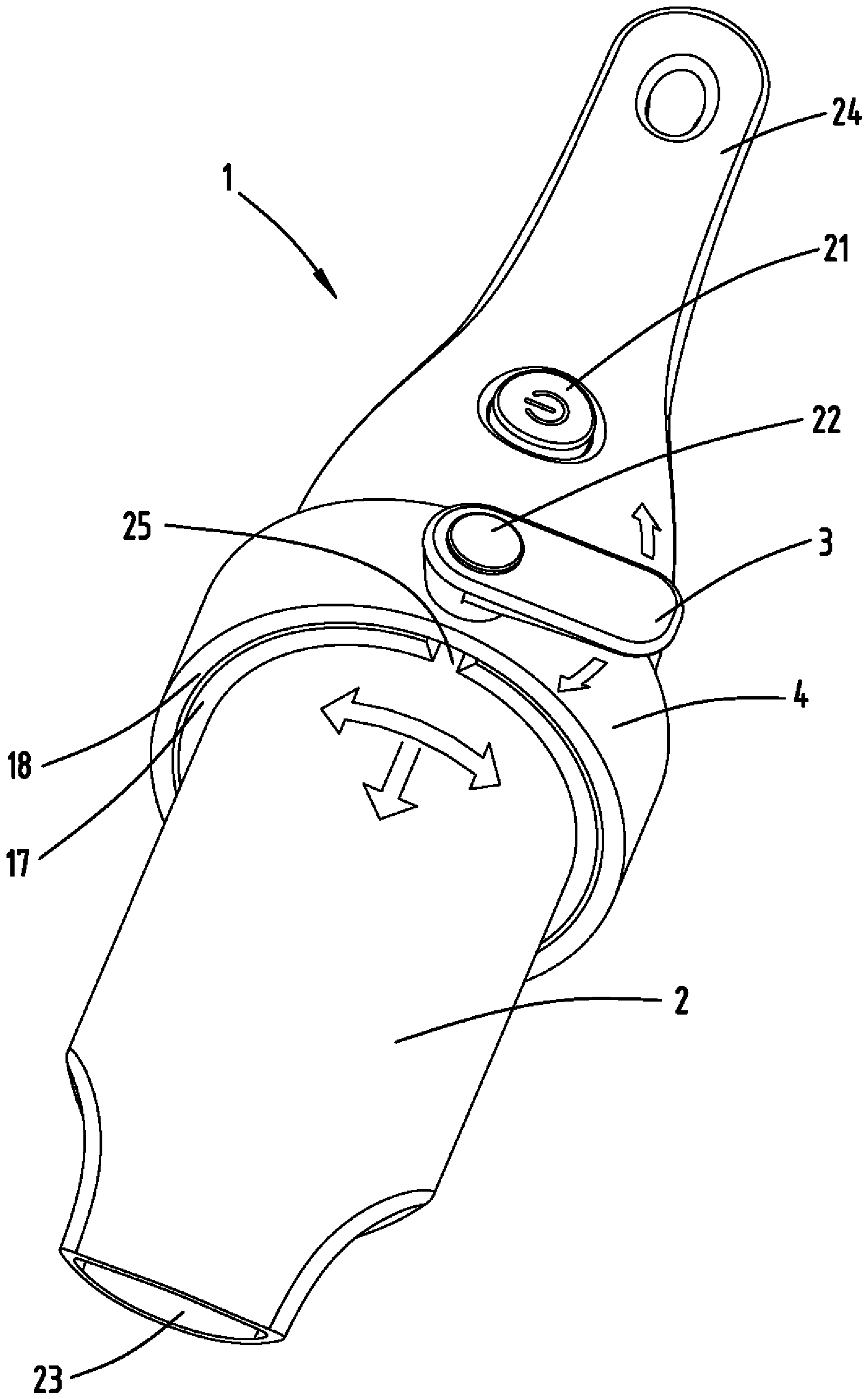
1 ein Elektrogerät mit einer erfindungsgemäßen Halteeinrichtung für einen Handgriff, -
2 eine perspektivische Darstellung der Halteeinrichtung, -
3 einen Querschnitt durch die Halteeinrichtung, -
4 einen vergrößerten Teilausschnitt der Halteeinrichtung gemäß3 in einer ersten Stellung, -
5 den in4 dargestellten Teilausschnitt der Halteeinrichtung in einer zweiten Stellung, -
6 eine Halteeinrichtung gemäß einer weiteren Ausführungsform, -
7 einen vergrößerten Teilausschnitt der Halteeinrichtung gemäß6 , -
8 eine Halteeinrichtung gemäß einer weiteren Ausführungsform, -
9 einen vergrößerten Teilausschnitt der Halteeinrichtung gemäß8 , -
10 eine Halteeinrichtung gemäß einer weiteren Ausführungsform, -
11 eine Halteeinrichtung gemäß einer weiteren Ausführungsform.
-
1 an electrical device with a holding device according to the invention for a handle, -
2nd a perspective view of the holding device, -
3rd a cross section through the holding device, -
4th an enlarged partial section of the holding device according to3rd in a first position, -
5 the in4th partial section of the holding device shown in a second position, -
6 a holding device according to a further embodiment, -
7 an enlarged partial section of the holding device according to6 , -
8th a holding device according to a further embodiment, -
9 an enlarged partial section of the holding device according to8th , -
10th a holding device according to a further embodiment, -
11 a holding device according to a further embodiment.
Beschreibung der AusführungsformenDescription of the embodiments
Die Halteeinrichtung
Die
Die
Die
Es kann zudem vorgesehen sein, dass die Verbindungselemente
Die
Obwohl die Erfindung in den Figuren beispielhaft anhand eines Reinigungsgerätes verdeutlicht wurde, versteht es sich, dass das Elektrogerät
BezugszeichenlisteReference list
- 11
- ElektrogerätElectrical appliance
- 22nd
- Gehäusecasing
- 33rd
- HandgriffHandle
- 44th
- HalteeinrichtungHolding device
- 55
- NutGroove
- 66
- Vorsprunghead Start
- 77
- VerbindungselementFastener
- 88th
- VerbindungselementFastener
- 99
- VerbindungselementFastener
- 1010th
- VerbindungselementFastener
- 1111
- VerbindungselementFastener
- 1212th
- VerbindungselementFastener
- 1313
- VerbindungselementFastener
- 1414
- VerbindungselementFastener
- 1515
- VerbindungselementFastener
- 1616
- VerbindungselementFastener
- 1717th
- RingelementRing element
- 1818th
- RingelementRing element
- 1919th
- KontaktschieneContact rail
- 2020th
- StromabnehmerPantograph
- 2121
- Schalterswitch
- 2222
- EntriegelungselementUnlocking element
- 2323
- SaugmundSuction mouth
- 2424th
- GehäusegriffHandle
- 2525th
- RingöffnungRing opening
- 2626
- DurchgangsöffnungThrough opening
- 2727
- FederelementSpring element
ZITATE ENTHALTEN IN DER BESCHREIBUNG QUOTES INCLUDE IN THE DESCRIPTION
Diese Liste der vom Anmelder aufgeführten Dokumente wurde automatisiert erzeugt und ist ausschließlich zur besseren Information des Lesers aufgenommen. Die Liste ist nicht Bestandteil der deutschen Patent- bzw. Gebrauchsmusteranmeldung. Das DPMA übernimmt keinerlei Haftung für etwaige Fehler oder Auslassungen.This list of documents listed by the applicant has been generated automatically and is only included for the better information of the reader. The list is not part of the German patent or utility model application. The DPMA assumes no liability for any errors or omissions.
Zitierte PatentliteraturPatent literature cited
- DE 102015118621 A1 [0005]DE 102015118621 A1 [0005]
Claims (8)
Priority Applications (6)
| Application Number | Priority Date | Filing Date | Title |
|---|---|---|---|
| DE102018121740.4A DE102018121740A1 (en) | 2018-09-06 | 2018-09-06 | Hand-held electrical device with a movable handle |
| TW108131346A TW202017715A (en) | 2018-09-06 | 2019-08-30 | Handheld electronic device with displaceable handle capable of making electronic device more convenient for user to operate |
| ES19194846T ES2969858T3 (en) | 2018-09-06 | 2019-09-02 | Portable electric device with movable handle |
| EP19194846.2A EP3623111B1 (en) | 2018-09-06 | 2019-09-02 | Hand-held electric appliance with a displaceable handle |
| JP2019159757A JP2020040201A (en) | 2018-09-06 | 2019-09-02 | Handheld-type electric device having displaceable handle |
| CN201910826748.XA CN110876585B (en) | 2018-09-06 | 2019-09-03 | Hand-held electrical device with movable handle |
Applications Claiming Priority (1)
| Application Number | Priority Date | Filing Date | Title |
|---|---|---|---|
| DE102018121740.4A DE102018121740A1 (en) | 2018-09-06 | 2018-09-06 | Hand-held electrical device with a movable handle |
Publications (1)
| Publication Number | Publication Date |
|---|---|
| DE102018121740A1 true DE102018121740A1 (en) | 2020-03-12 |
Family
ID=67840953
Family Applications (1)
| Application Number | Title | Priority Date | Filing Date |
|---|---|---|---|
| DE102018121740.4A Withdrawn DE102018121740A1 (en) | 2018-09-06 | 2018-09-06 | Hand-held electrical device with a movable handle |
Country Status (6)
| Country | Link |
|---|---|
| EP (1) | EP3623111B1 (en) |
| JP (1) | JP2020040201A (en) |
| CN (1) | CN110876585B (en) |
| DE (1) | DE102018121740A1 (en) |
| ES (1) | ES2969858T3 (en) |
| TW (1) | TW202017715A (en) |
Cited By (1)
| Publication number | Priority date | Publication date | Assignee | Title |
|---|---|---|---|---|
| DE102023118984A1 (en) * | 2023-07-18 | 2025-01-23 | Miele & Cie. Kg | Combined locking element for use with a fixed component and a movable component |
Families Citing this family (1)
| Publication number | Priority date | Publication date | Assignee | Title |
|---|---|---|---|---|
| DE102022134161A1 (en) | 2021-12-22 | 2023-06-22 | Festool Gmbh | Hand machine tool with handle housing part that can be mounted in angular positions |
Citations (6)
| Publication number | Priority date | Publication date | Assignee | Title |
|---|---|---|---|---|
| DE102006055014A1 (en) * | 2006-11-22 | 2008-05-29 | Robert Bosch Gmbh | Additional handle with eccentric clamping lever for a hand tool |
| DE102007047030A1 (en) * | 2007-10-01 | 2009-04-02 | Metabowerke Gmbh | Electric hand tool |
| DE102009000598A1 (en) * | 2008-02-15 | 2009-08-20 | Robert Bosch Gmbh | Vibration-decoupled handle |
| DE102011010039A1 (en) * | 2011-01-28 | 2012-08-02 | C. & E. Fein Gmbh | Power tool has housing, on which spindle collar is provided with clamping portion, where handle grip is fixed on clamping portion by using clamping strap |
| WO2015007323A1 (en) * | 2013-07-18 | 2015-01-22 | Alfred Kärcher Gmbh & Co. Kg | Appliance holder for a portable hard-surface cleaning appliance |
| US20170273251A1 (en) * | 2016-03-23 | 2017-09-28 | Yamabiko Corporation | Blow operation device |
Family Cites Families (6)
| Publication number | Priority date | Publication date | Assignee | Title |
|---|---|---|---|---|
| DE102004003202B4 (en) * | 2004-01-22 | 2022-05-25 | Robert Bosch Gmbh | Handle with detection device |
| DE102008000516A1 (en) * | 2008-03-05 | 2009-09-10 | Robert Bosch Gmbh | Additional handle and hand tool |
| DE102009027570A1 (en) * | 2009-07-09 | 2011-01-13 | Robert Bosch Gmbh | Device for positioning and fixing a device, in particular a handle on a power tool |
| DE102009047394A1 (en) * | 2009-12-02 | 2011-06-09 | Robert Bosch Gmbh | Hand machine tool device |
| DE102013202832A1 (en) * | 2013-02-21 | 2014-08-21 | Robert Bosch Gmbh | Hand tool and method for operating the hand tool |
| DE102015118621B4 (en) | 2015-10-30 | 2024-09-19 | Vorwerk & Co. Interholding Gmbh | Cleaning device with a pivoting handle |
-
2018
- 2018-09-06 DE DE102018121740.4A patent/DE102018121740A1/en not_active Withdrawn
-
2019
- 2019-08-30 TW TW108131346A patent/TW202017715A/en unknown
- 2019-09-02 JP JP2019159757A patent/JP2020040201A/en active Pending
- 2019-09-02 ES ES19194846T patent/ES2969858T3/en active Active
- 2019-09-02 EP EP19194846.2A patent/EP3623111B1/en active Active
- 2019-09-03 CN CN201910826748.XA patent/CN110876585B/en active Active
Patent Citations (6)
| Publication number | Priority date | Publication date | Assignee | Title |
|---|---|---|---|---|
| DE102006055014A1 (en) * | 2006-11-22 | 2008-05-29 | Robert Bosch Gmbh | Additional handle with eccentric clamping lever for a hand tool |
| DE102007047030A1 (en) * | 2007-10-01 | 2009-04-02 | Metabowerke Gmbh | Electric hand tool |
| DE102009000598A1 (en) * | 2008-02-15 | 2009-08-20 | Robert Bosch Gmbh | Vibration-decoupled handle |
| DE102011010039A1 (en) * | 2011-01-28 | 2012-08-02 | C. & E. Fein Gmbh | Power tool has housing, on which spindle collar is provided with clamping portion, where handle grip is fixed on clamping portion by using clamping strap |
| WO2015007323A1 (en) * | 2013-07-18 | 2015-01-22 | Alfred Kärcher Gmbh & Co. Kg | Appliance holder for a portable hard-surface cleaning appliance |
| US20170273251A1 (en) * | 2016-03-23 | 2017-09-28 | Yamabiko Corporation | Blow operation device |
Cited By (2)
| Publication number | Priority date | Publication date | Assignee | Title |
|---|---|---|---|---|
| DE102023118984A1 (en) * | 2023-07-18 | 2025-01-23 | Miele & Cie. Kg | Combined locking element for use with a fixed component and a movable component |
| DE102023118984B4 (en) * | 2023-07-18 | 2026-02-05 | Miele & Cie. Kg | Household appliance with a combined safety element for use with a fixed component and a moving component |
Also Published As
| Publication number | Publication date |
|---|---|
| CN110876585A (en) | 2020-03-13 |
| JP2020040201A (en) | 2020-03-19 |
| CN110876585B (en) | 2022-07-05 |
| TW202017715A (en) | 2020-05-16 |
| EP3623111C0 (en) | 2023-11-01 |
| EP3623111A1 (en) | 2020-03-18 |
| ES2969858T3 (en) | 2024-05-23 |
| EP3623111B1 (en) | 2023-11-01 |
Similar Documents
| Publication | Publication Date | Title |
|---|---|---|
| DE69218051T2 (en) | Striking tool holder | |
| DE69528980T2 (en) | CHUCK | |
| EP2745992B1 (en) | Tool attachment for a manual tool machine | |
| EP0661025B1 (en) | Cleaning tool for teeth | |
| DE202014101301U1 (en) | power tool | |
| DE102015204806B4 (en) | hand-held power tool | |
| EP3315263A1 (en) | Hand-held machine tool comprising a shiftable gearbox | |
| EP3263289B1 (en) | Handheld machine tool | |
| DE102020001377A1 (en) | Work tool | |
| DE112018003406T5 (en) | Ratchet wrench | |
| DE102004058175A1 (en) | Hand tool | |
| DE102010013252A1 (en) | Hand-held cleaning device for cleaning pipelines | |
| DE202017101409U1 (en) | Auxiliary handle and working tool | |
| DE102018127090A1 (en) | Hand-held cleaning device | |
| EP2539094A1 (en) | Handheld machine tool | |
| EP3623111B1 (en) | Hand-held electric appliance with a displaceable handle | |
| DE102014217992B4 (en) | Battery pack for a hand tool | |
| DE102012203221A1 (en) | Hand tool machine, particularly for use as screwdriver, has tool insert with electrically conductive actuating sleeve which is surrounded partially by insulating sleeve arranged on tool housing | |
| DE102019102667A1 (en) | Screwdriver with gear ratio | |
| DE102020201243B3 (en) | Quick-change chuck for reversible locking of an insert tool on a processing device | |
| EP3260237A1 (en) | Long-shafted tool, system consisting of a long-shafted tool with a first manipulator and a second manipulator and use for such a tool and such a system | |
| DE102020108873A1 (en) | Tool for pressing and / or expanding a pipe section | |
| DE10260324A1 (en) | Cordless, electric power tool for workers, has cover to enclose outer peripheries of fastening screws and stopper to detachably position cover on outer periphery of hammer case | |
| DE102019128050B4 (en) | Vacuum cleaning device with a chamber lid with a locking device | |
| EP2110208A1 (en) | Telescopic handle with locking device |
Legal Events
| Date | Code | Title | Description |
|---|---|---|---|
| R083 | Amendment of/additions to inventor(s) | ||
| R163 | Identified publications notified | ||
| R005 | Application deemed withdrawn due to failure to request examination |