DE102018108829A1 - retaining element - Google Patents
retaining element Download PDFInfo
- Publication number
- DE102018108829A1 DE102018108829A1 DE102018108829.9A DE102018108829A DE102018108829A1 DE 102018108829 A1 DE102018108829 A1 DE 102018108829A1 DE 102018108829 A DE102018108829 A DE 102018108829A DE 102018108829 A1 DE102018108829 A1 DE 102018108829A1
- Authority
- DE
- Germany
- Prior art keywords
- spacer
- vehicle component
- threaded
- retaining
- holding
- Prior art date
- Legal status (The legal status is an assumption and is not a legal conclusion. Google has not performed a legal analysis and makes no representation as to the accuracy of the status listed.)
- Pending
Links
- 125000006850 spacer group Chemical group 0.000 claims abstract description 142
- 239000000463 material Substances 0.000 claims abstract description 18
- 229920002725 thermoplastic elastomer Polymers 0.000 claims description 5
- 238000001746 injection moulding Methods 0.000 description 7
- 239000004033 plastic Substances 0.000 description 6
- 230000000694 effects Effects 0.000 description 4
- 230000006978 adaptation Effects 0.000 description 3
- 238000007789 sealing Methods 0.000 description 3
- 238000003780 insertion Methods 0.000 description 2
- 230000037431 insertion Effects 0.000 description 2
- 230000000284 resting effect Effects 0.000 description 2
- 230000002441 reversible effect Effects 0.000 description 2
- 238000003466 welding Methods 0.000 description 2
- BUHVIAUBTBOHAG-FOYDDCNASA-N (2r,3r,4s,5r)-2-[6-[[2-(3,5-dimethoxyphenyl)-2-(2-methylphenyl)ethyl]amino]purin-9-yl]-5-(hydroxymethyl)oxolane-3,4-diol Chemical compound COC1=CC(OC)=CC(C(CNC=2C=3N=CN(C=3N=CN=2)[C@H]2[C@@H]([C@H](O)[C@@H](CO)O2)O)C=2C(=CC=CC=2)C)=C1 BUHVIAUBTBOHAG-FOYDDCNASA-N 0.000 description 1
- 238000004026 adhesive bonding Methods 0.000 description 1
- 230000001419 dependent effect Effects 0.000 description 1
- 230000000670 limiting effect Effects 0.000 description 1
- 239000007788 liquid Substances 0.000 description 1
- 230000014759 maintenance of location Effects 0.000 description 1
- 230000036961 partial effect Effects 0.000 description 1
- 238000011084 recovery Methods 0.000 description 1
- 230000002829 reductive effect Effects 0.000 description 1
- 239000007787 solid Substances 0.000 description 1
- 239000000243 solution Substances 0.000 description 1
Images
Classifications
-
- B—PERFORMING OPERATIONS; TRANSPORTING
- B62—LAND VEHICLES FOR TRAVELLING OTHERWISE THAN ON RAILS
- B62D—MOTOR VEHICLES; TRAILERS
- B62D27/00—Connections between superstructure or understructure sub-units
- B62D27/06—Connections between superstructure or understructure sub-units readily releasable
- B62D27/065—Connections between superstructure or understructure sub-units readily releasable using screwthread
-
- F—MECHANICAL ENGINEERING; LIGHTING; HEATING; WEAPONS; BLASTING
- F16—ENGINEERING ELEMENTS AND UNITS; GENERAL MEASURES FOR PRODUCING AND MAINTAINING EFFECTIVE FUNCTIONING OF MACHINES OR INSTALLATIONS; THERMAL INSULATION IN GENERAL
- F16B—DEVICES FOR FASTENING OR SECURING CONSTRUCTIONAL ELEMENTS OR MACHINE PARTS TOGETHER, e.g. NAILS, BOLTS, CIRCLIPS, CLAMPS, CLIPS OR WEDGES; JOINTS OR JOINTING
- F16B37/00—Nuts or like thread-engaging members
- F16B37/04—Devices for fastening nuts to surfaces, e.g. sheets, plates
- F16B37/041—Releasable devices
- F16B37/043—Releasable devices with snap action
-
- F—MECHANICAL ENGINEERING; LIGHTING; HEATING; WEAPONS; BLASTING
- F16—ENGINEERING ELEMENTS AND UNITS; GENERAL MEASURES FOR PRODUCING AND MAINTAINING EFFECTIVE FUNCTIONING OF MACHINES OR INSTALLATIONS; THERMAL INSULATION IN GENERAL
- F16B—DEVICES FOR FASTENING OR SECURING CONSTRUCTIONAL ELEMENTS OR MACHINE PARTS TOGETHER, e.g. NAILS, BOLTS, CIRCLIPS, CLAMPS, CLIPS OR WEDGES; JOINTS OR JOINTING
- F16B5/00—Joining sheets or plates, e.g. panels, to one another or to strips or bars parallel to them
- F16B5/02—Joining sheets or plates, e.g. panels, to one another or to strips or bars parallel to them by means of fastening members using screw-thread
- F16B5/0216—Joining sheets or plates, e.g. panels, to one another or to strips or bars parallel to them by means of fastening members using screw-thread the position of the plates to be connected being adjustable
- F16B5/0233—Joining sheets or plates, e.g. panels, to one another or to strips or bars parallel to them by means of fastening members using screw-thread the position of the plates to be connected being adjustable allowing for adjustment perpendicular to the plane of the plates
-
- B—PERFORMING OPERATIONS; TRANSPORTING
- B62—LAND VEHICLES FOR TRAVELLING OTHERWISE THAN ON RAILS
- B62D—MOTOR VEHICLES; TRAILERS
- B62D25/00—Superstructure or monocoque structure sub-units; Parts or details thereof not otherwise provided for
- B62D25/08—Front or rear portions
-
- F—MECHANICAL ENGINEERING; LIGHTING; HEATING; WEAPONS; BLASTING
- F16—ENGINEERING ELEMENTS AND UNITS; GENERAL MEASURES FOR PRODUCING AND MAINTAINING EFFECTIVE FUNCTIONING OF MACHINES OR INSTALLATIONS; THERMAL INSULATION IN GENERAL
- F16B—DEVICES FOR FASTENING OR SECURING CONSTRUCTIONAL ELEMENTS OR MACHINE PARTS TOGETHER, e.g. NAILS, BOLTS, CIRCLIPS, CLAMPS, CLIPS OR WEDGES; JOINTS OR JOINTING
- F16B37/00—Nuts or like thread-engaging members
- F16B37/14—Cap nuts; Nut caps or bolt caps
- F16B37/145—Sleeve nuts, e.g. combined with bolts
Landscapes
- Engineering & Computer Science (AREA)
- General Engineering & Computer Science (AREA)
- Mechanical Engineering (AREA)
- Chemical & Material Sciences (AREA)
- Combustion & Propulsion (AREA)
- Transportation (AREA)
- Connection Of Plates (AREA)
Abstract
Die Erfindung betrifft ein Halteelement zum Halten einer ersten Fahrzeugkomponente, vorzugsweise eines Anbauteils, an einer zweiten Fahrzeugkomponente, vorzugsweise einem Trägerteil, wobei das Halteelement ein mit der ersten Fahrzeugkomponente verbindbares Verbindungsteil sowie ein Distanzteil umfasst, wobei das Distanzteil und das Verbindungsteil in einer Axialrichtung verstellbar miteinander verbunden oder verbindbar sind, und wobei das Distanzteil eine Oberfläche aus einem ersten Material aufweist und die zweite Fahrzeugkomponente an dem Distanzteil gehalten werden kann, so dass die Oberfläche des Distanzteils der zweiten Fahrzeugkomponente zugewandt ist, wobei ein Anlageelement aus einem zweiten Material vorgesehen ist, wobei das zweite Material weicher ist als das erste Material, und wobei das Anlageelement eine Anlagefläche aufweist, die dazu ausgebildet ist, im an dem Distanzteil gehaltenen Zustand der zweiten Fahrzeugkomponente an der zweiten Fahrzeugkomponente anzuliegen.
Description
Die Erfindung betrifft ein Halteelement zum Halten einer ersten Fahrzeugkomponente, vorzugsweise eines Anbauteils, an einer zweiten Fahrzeugkomponente, vorzugsweise einem Trägerteil, wobei das Halteelement ein mit der ersten Fahrzeugkomponente verbindbares Verbindungsteil sowie ein Distanzteil umfasst, wobei das Distanzteil und das Verbindungsteil in einer Axialrichtung verstellbar miteinander verbunden oder verbindbar sind, und wobei das Distanzteil eine Oberfläche aus einem ersten Material aufweist und die zweite Fahrzeugkomponente an dem Distanzteil gehalten werden kann, so dass die Oberfläche des Distanzteils der zweiten Fahrzeugkomponente zugewandt ist.The invention relates to a holding element for holding a first vehicle component, preferably an attachment, on a second vehicle component, preferably a carrier part, wherein the holding element comprises a connectable with the first vehicle component connecting part and a spacer, wherein the spacer and the connecting part in an axial direction adjustable with each other are connected or connectable, and wherein the spacer has a surface of a first material and the second vehicle component can be held on the spacer, so that the surface of the spacer faces the second vehicle component.
Mit derartigen Halteelementen können Anbauteile zum Beispiel an Karosserieteilen von Automobilen gehalten werden. Bei den Anbauteilen kann es sich zum Beispiel um Anbauteile für den Außenbereich des Automobils, wie Gehäuse für Fahrzeuglichtern handeln. Aufgrund von Positionstoleranzen kann der Abstand zwischen dem Anbauteil und dem Trägerteil, beispielsweise einem Karosserieteil, variieren. Um eine jederzeit feste Verbindung unter Vermeidung unerwünschter Geräuschbildung sicherzustellen, können hinsichtlich ihrer axialen Position anpassbare Distanzteile vorgesehen sein, die sich im fertig montierten Zustand an einer dem Bauteil zugewandten Seite des Trägerteils anlegen.With such holding elements attachments can be kept, for example, on body parts of automobiles. The attachments may be, for example, attachments for the exterior of the automobile, such as housing for vehicle lights. Due to positional tolerances, the distance between the attachment and the support member, such as a body part, vary. In order to ensure an always solid connection while avoiding unwanted noise, can be provided with respect to their axial position adjustable spacers, which create in the assembled state on a component side facing the support member.
Aus
Aus
Bei bekannten Halteelementen, bei denen das Trägerteil an einer Oberfläche des Distanzteils anliegt, kann es im Betrieb zu unerwünschter Geräuschentwicklung kommen. Dies gilt insbesondere bei den für eine ausreichende Belastbarkeit der Komponenten des Halteelements erforderlichen Materialien.In known holding elements, in which the carrier part rests against a surface of the spacer, it may cause undesirable noise during operation. This applies in particular to the materials required for a sufficient load capacity of the components of the holding element.
Ausgehend von dem erläuterten Stand der Technik liegt der Erfindung die Aufgabe zugrunde, ein Halteelement der eingangs genannten Art bereitzustellen, dass bei jederzeit ausreichender Belastbarkeit eine unerwünschte Geräuschentwicklung vermeidet.Based on the explained prior art, the present invention seeks to provide a holding element of the type mentioned that at any time sufficient load capacity avoids unwanted noise.
Die Erfindung löst die Aufgabe durch den Gegenstand von Anspruch 1. Vorteilhafte Ausgestaltungen finden sich in den abhängigen Ansprüchen, der Beschreibung und den Figuren.The invention achieves the object by the subject matter of claim 1. Advantageous embodiments can be found in the dependent claims, the description and the figures.
Für ein Halteelement der eingangs genannten Art löst die Erfindung die Aufgabe dadurch, dass ein Anlageelement aus einem zweiten Material vorgesehen ist, wobei das zweite Material weicher ist als das erste Material, und wobei das Anlageelement eine Anlagefläche aufweist, die dazu ausgebildet ist, im an dem Distanzteil gehaltenen Zustand der zweiten Fahrzeugkomponente an der zweiten Fahrzeugkomponente anzuliegen.For a retaining element of the type mentioned, the invention solves the problem in that a contact element is provided of a second material, wherein the second material is softer than the first material, and wherein the abutment element has a contact surface, which is adapted to the in the spacer held state of the second Vehicle component to abut the second vehicle component.
Das Anlageelement kann an dem Distanzteil angeordnet sein. Es bildet eine aus einem gegenüber dem Material der Oberfläche des Distanzteils weicheren Material bestehende Anlagefläche aus, die im montierten Zustand an der zweiten Fahrzeugkomponente, beispielsweise einem Trägerteil, anliegt. Auf diese Weise können Geräusche aufgrund eines direkten Kontakts zwischen der Oberfläche des Distanzteils und der zweiten Fahrzeugkomponente vermieden oder zumindest vermindert werden. Die Anlagefläche kann insbesondere dazu ausgebildet sein, im an dem Distanzteil gehaltenen Zustand der zweiten Fahrzeugkomponente an die zweite Fahrzeugkomponente angedrückt zu werden. Hierdurch wird eine besonders gute Geräuschminderung erreicht. Es ist weiterhin möglich, dass im an dem Distanzteil gehaltenen Zustand der zweiten Fahrzeugkomponente nur die Anlagefläche des Anlageelements an der zweiten Fahrzeugkomponente anliegt, nicht jedoch die Oberfläche des Distanzteils. Neben der Geräuschminderung kann durch die an der zweiten Fahrzeugkomponente anliegende Anlagefläche des Anlageelements auch eine Dichtwirkung gegenüber einem Durchtritt von Flüssigkeiten oder ähnlichem erreicht werden.The contact element can be arranged on the spacer. It forms a bearing surface which is made of a material that is softer than the material of the surface of the spacer and, in the mounted state, rests against the second vehicle component, for example a carrier part. In this way, noise due to direct contact between the surface of the spacer and the second vehicle component can be avoided or at least reduced. In particular, the contact surface can be designed to be pressed against the second vehicle component in the state of the second vehicle component held on the spacer part. As a result, a particularly good noise reduction is achieved. It is also possible that in the state held on the spacer part of the second vehicle component, only the contact surface of the abutment element bears against the second vehicle component, but not the surface of the spacer. In addition to the noise reduction can be achieved by the voltage applied to the second vehicle component contact surface of the contact element, a sealing effect against a passage of liquids or the like.
Gleichzeitig kann bei dem erfindungsgemäßen Halteelement in an sich bekannter Weise die axiale Relativposition zwischen Distanzteil und Verbindungsteil angepasst werden. Die Axialrichtung kann senkrecht zur Oberfläche des Distanzteils bzw. zur Anlagefläche des Anlageelements verlaufen. Indem einerseits die erste Fahrzeugkomponente mit dem Verbindungsteil verbindbar ist bzw. durch das Verbindungsteil gehalten werden kann, und andererseits die zweite Fahrzeugkomponente an dem Distanzteil gehalten werden kann, kann durch eine axiale Relativbewegung zwischen Distanzteil und Verbindungsteil in an sich bekannter Weise ein Toleranzausgleich in Bezug auf die Position der ersten und zweiten Fahrzeugkomponente erfolgen.At the same time, the axial relative position between the spacer and the connecting part can be adjusted in a manner known per se in the holding element according to the invention. The axial direction can extend perpendicular to the surface of the spacer or to the contact surface of the contact element. By on the one hand the first vehicle component is connectable to the connecting part or can be held by the connecting part, and on the other hand, the second vehicle component can be held on the spacer, can by an axial relative movement between the spacer and connecting part in a conventional manner a tolerance compensation with respect to the position of the first and second vehicle components take place.
Die erste Fahrzeugkomponente kann wie erläutert ein Anbauteil eines Fahrzeugs sein. Die zweite Fahrzeugkomponente kann wie erläutert ein Trägerteil eines Fahrzeugs sein. Bei dem Fahrzeug kann es sich beispielsweise um einen PKW oder LKW handeln. Das Anbauteil kann zum Beispiel ein Anbauteil für den Außenbereich des Fahrzeugs sein. Beispielsweise kann es sich bei dem Anbauteil um ein Gehäuseteil handeln, zum Beispiel für eine Außenleuchte des Fahrzeugs. Das Distanzteil kann aus Kunststoff bestehen. Es kann zum Beispiel in einem Spritzgussverfahren hergestellt sein. Auch das Verbindungsteil kann aus Kunststoff bestehen. Es kann ebenfalls in einem Spritzgussverfahren hergestellt sein. Auch das Anlageelement kann aus einem Kunststoff bestehen, hergestellt beispielsweise in einem Spritzgussverfahren. Das Distanzteil kann eine zum Beispiel hohlzylindrische Grundform besitzen.The first vehicle component may be as described an attachment of a vehicle. As explained, the second vehicle component may be a carrier part of a vehicle. The vehicle may be, for example, a car or truck. The attachment may be, for example, an attachment for the exterior of the vehicle. For example, the attachment may be a housing part, for example for an exterior light of the vehicle. The spacer can be made of plastic. It can be made, for example, in an injection molding process. Also, the connecting part may consist of plastic. It may also be made by injection molding. Also, the contact element may consist of a plastic, prepared for example in an injection molding process. The spacer may have, for example, a hollow cylindrical basic shape.
Gemäß einer die Geräuschminderung weiter optimierenden Ausgestaltung kann die Anlagefläche über die Oberfläche des Distanzteils überstehen, insbesondere in der Axialrichtung.According to an embodiment further optimizing the noise reduction, the contact surface can project beyond the surface of the spacer, in particular in the axial direction.
Zur weiteren Verbesserung der Geräuschminderung und einer gegebenenfalls zusätzlichen Abdichtwirkung kann die Anlagefläche nach einer weiteren Ausgestaltung ringförmig geschlossen ausgebildet sein.To further improve the noise reduction and optionally additional sealing effect, the contact surface may be formed annularly closed according to a further embodiment.
Das Anlageelement kann gemäß einer weiteren Ausgestaltung eine Durchgangsöffnung für eine Halteschraube zum Halten der zweiten Fahrzeugkomponente an dem Distanzteil begrenzen. Die Einführrichtung der Halteschraube zum Halten der zweiten Fahrzeugkomponente bzw. die Längsachse der Halteschraube definiert dann gleichzeitig die Axialrichtung.The abutment element can, according to a further embodiment, delimit a passage opening for a retaining screw for holding the second vehicle component on the spacer part. The insertion direction of the retaining screw for holding the second vehicle component or the longitudinal axis of the retaining screw then simultaneously defines the axial direction.
Das Halteelement kann gemäß einer weiteren Ausgestaltung einen Klemmabschnitt aufweisen, der dazu ausgebildet ist, eine durch die Durchgangsöffnung des Distanzteils geführte Halteschraube zu kontaktieren, so dass ein Drehmoment von der Halteeschraube auf das Distanzteil übertragbar ist, wobei der Klemmabschnitt durch das Anlageelement ausgebildet ist. Der Klemmabschnitt kann zum Beispiel einen gegenüber dem übrigen Querschnitt der Durchgangsöffnung verengten Querschnitt bilden. Der verengte Querschnitt ist derart ausgebildet, dass eine z. B. in ein Innengewinde des Verbindungsteils einzuschraubende Halteschraube aufgrund ihres Durchmessers klemmend an dem Klemmabschnitt anliegt. Dadurch wird ein Reibschluss erzeugt. Es erfolgt eine klemmende Mitnahme bei einer Drehung der Halteschraube, wie sie zum Einschrauben in das Innengewinde des Verbindungsteils erfolgt. Das Distanzteil dreht sich also mit der Halteschraube mit. Dadurch kann im Zuge des Einschraubens der Halteschraube in das Verbindungsteil ein Schrauben des Distanzteils auf bzw. in einem mit einem Gewinde des Distanzteils zusammenwirkenden Gewinde des Verbindungsteils erfolgen.According to a further embodiment, the retaining element may have a clamping section which is designed to contact a retaining screw guided through the passage opening of the spacer, so that a torque can be transmitted from the retaining screw to the spacer, wherein the clamping section is formed by the contact element. The clamping portion may, for example, form a cross-section which is narrower than the remaining cross-section of the passage opening. The narrowed cross-section is formed such that a z. B. screwed into an internal thread of the connecting part holding screw due to their diameter clamped against the clamping portion. This creates a frictional connection. There is a clamping entrainment with a rotation of the retaining screw, as it is done for screwing into the internal thread of the connecting part. The spacer thus rotates with the retaining screw. As a result, in the course of screwing the retaining screw into the connecting part, the spacer can be screwed on or in a thread of the connecting part cooperating with a thread of the spacer.
Gemäß einer weiteren Ausgestaltung kann das Anlageelement durch einen in das Distanzteil eingesetzten Einsatz gebildet sein. Der Einsatz kann hohlzylindrisch sein. Der Einsatz kann beispielsweise in einen Kopfabschnitt des Distanzteils eingesetzt sein. Er kann eine mit einem Innengewinde des Verbindungsteils fluchtende Durchgangsöffnung bilden. In dieser Durchgangsöffnung kann dann der mindestens eine Klemmabschnitt ausgebildet sein. Der Kopfabschnitt kann die Oberfläche des Distanzteils bilden. Der Einsatz kann dann geringfügig über die Oberfläche vorstehen. Die Anlagefläche kann gemäß einer weiteren diesbezüglichen Ausgestaltung durch einen ringförmigen Anlageflansch des Einsatzes gebildet sein.According to a further embodiment, the abutment element may be formed by an insert inserted into the spacer. The insert can be hollow cylindrical. The insert can be used for example in a head portion of the spacer. It can form a passage opening aligned with an internal thread of the connecting part. The at least one clamping section can then be formed in this passage opening. The head portion may form the surface of the spacer. The insert can then slightly over the Protruding surface. The contact surface can be formed according to a further related embodiment by an annular abutment flange of the insert.
Für eine besonders gute Geräuschminderung und gegebenenfalls Dichtwirkung kann das Anlageelement aus einem thermoplastischen Elastomer (TPE) bestehen. Ein solches Material bietet außerdem einen guten Reibschluss und eine ausreichende Elastizität, so dass der Klemmabschnitt seine Wirkung besonders gut entfalten kann und auch bei mehrfacher Montage und Demontage keine Beschädigung des Klemmabschnitts eintritt. Der Klemmabschnitt kann zum Beispiel in einem Zweikomponenten-Spritzgussverfahren an einen Grundkörper des Distanzteils angespritzt sein. Entsprechend kann auch der das Anlageelement bildende Einsatz in einem Zweikomponenten-Spritzgussverfahren an den Grundkörper des Distanzteils angespritzt sein. Der Einsatz könnte aber auch anderweitig an dem Distanzteil gehalten sein, beispielsweise durch Verrastung.For a particularly good noise reduction and optionally sealing effect, the contact element may consist of a thermoplastic elastomer (TPE). Such a material also offers a good frictional engagement and sufficient elasticity, so that the clamping portion can develop its effect particularly well and no damage to the clamping portion occurs even with multiple assembly and disassembly. The clamping portion may be molded onto a base body of the spacer, for example, in a two-component injection molding process. Correspondingly, the insert forming the abutment element can also be molded onto the main body of the spacer in a two-component injection molding process. The insert could also be held elsewhere on the spacer, for example by locking.
Das Verbindungsteil kann nach einer weiteren Ausgestaltung ein mit der ersten Fahrzeugkomponente verbindbares Gewindeteil sein und das Distanzteil und das Gewindeteil können zusammenwirkende Gewinde aufweisen, so dass das Distanzteil mit dem Gewindeteil verschraubt werden kann. Beispielsweise kann das Gewindeteil ein Außengewinde aufweisen und das Distanzteil ein Innengewinde aufweisen, mit dem es auf das Außengewinde des Gewindeteils aufgeschraubt werden kann. Es wäre allerdings auch eine umgekehrte Ausgestaltung möglich, bei der das Gewindeteil ein Innengewinde und das Distanzteil ein Außengewinde aufweist, mit dem es in das Innengewinde des Gewindeteils eingeschraubt werden kann. Durch diese Ausgestaltungen kann die axiale Relativposition zwischen Gewindeteil und Distanzteil in besonders einfacher Weise eingestellt werden.The connecting part may be connectable to the first vehicle component threaded part according to a further embodiment and the spacer and the threaded portion may have cooperating threads, so that the spacer can be screwed to the threaded portion. For example, the threaded part may have an external thread and the spacer part have an internal thread, with which it can be screwed onto the external thread of the threaded part. However, it would also be a reverse configuration possible in which the threaded part has an internal thread and the spacer has an external thread with which it can be screwed into the internal thread of the threaded part. By these embodiments, the axial relative position between the threaded part and spacer can be adjusted in a particularly simple manner.
Die Erfindung betrifft auch ein System aus einer ersten Fahrzeugkomponente, vorzugsweise einem Anbauteil, und einem erfindungsgemäßen Halteelement, wobei das Verbindungsteil ein mit der ersten Fahrzeugkomponente verbindbares Gewindeteil mit einem Innengewinde für eine Halteschraube ist, wobei das Distanzteil eine im mit dem Gewindeteil verschraubten Zustand mit dem Innengewinde des Gewindeteils fluchtende Durchgangsöffnung für die Halteschraube aufweist. Die zweite Fahrzeugkomponente kann dabei zwischen einem Kopf der Halteschraube und dem Distanzteil gehalten werden, so dass die Anlagefläche des Anlageelements an der zweiten Fahrzeugkomponente anliegt, vorzugsweise an diese angedrückt wird.The invention also relates to a system comprising a first vehicle component, preferably an attachment, and a retaining element according to the invention, wherein the connecting part is a threaded part connectable to the first vehicle component with an internal thread for a retaining screw, wherein the spacer part has a state bolted to the threaded part Internal thread of the threaded part has aligned through hole for the retaining screw. The second vehicle component can be held between a head of the retaining screw and the spacer, so that the contact surface of the contact element rests against the second vehicle component, preferably is pressed against this.
Das Gewindeteil des Halteelements weist ein Innengewinde auf, in das eine Halteschraube eingeschraubt werden kann. Außerdem weist das Distanzteil ein Gewinde auf, das mit einem korrespondierenden Gewinde des Gewindeteils zusammenwirkt, so dass das Distanzteil mit dem Gewindeteil verschraubt werden kann. The threaded portion of the retaining element has an internal thread into which a retaining screw can be screwed. In addition, the spacer has a thread which cooperates with a corresponding thread of the threaded part, so that the spacer can be screwed to the threaded part.
Das Distanzteil weist eine Durchgangsöffnung auf, die bei mit dem Gewindeteil verschraubtem Distanzteil mit dem Innengewinde des Gewindeteils fluchtet. Die Halteschraube kann folglich durch die Durchgangsöffnung des Distanzteils hindurch in das Innengewinde des Gewindeteils eingeschraubt werden. Vor dem Einschrauben der Halteschraube kann die zweite Fahrzeugkomponente, beispielsweise ein Trägerteil, mit einer Durchgangsöffnung so auf das Distanzteil aufgelegt werden, dass die Durchgangsöffnung der zweiten Fahrzeugkomponente mit der Durchgangsöffnung des Distanzteils fluchtet. Anschließend kann die Halteschraube durch die Durchgangsöffnung der zweiten Fahrzeugkomponente und die Durchgangsöffnung des Distanzteils hindurch in das Innengewinde des Gewindeteils eingeschraubt werden. Die zweite Fahrzeugkomponente kann auf diese Weise wie erläutert beispielsweise zwischen einem Kopf der Halteschraube und dem Distanzteil klemmend gehalten werden. Das Einschrauben der Halteschraube kann zum Beispiel von der Innenseite des Karosserieteils erfolgen, wenn es sich bei der ersten Fahrzeugkomponente, insbesondere dem Anbauteil, um ein Außenteil des Fahrzeugs handelt. Die erste Fahrzeugkomponente wird an dem Gewindeteil des Halteelements gehalten, so dass auf diese Weise die erste Fahrzeugkomponente an der zweiten Fahrzeugkomponente gehalten ist.The spacer has a through opening, which is aligned with screwed to the threaded part spacer with the internal thread of the threaded part. The retaining screw can consequently be screwed through the passage opening of the spacer into the internal thread of the threaded part. Before screwing in the retaining screw, the second vehicle component, for example a carrier part, can be placed onto the spacer with a passage opening in such a way that the passage opening of the second vehicle component is aligned with the passage opening of the spacer. Subsequently, the retaining screw can be screwed through the passage opening of the second vehicle component and the passage opening of the spacer into the internal thread of the threaded part. The second vehicle component can be clamped in this way, as explained, for example, between a head of the retaining screw and the spacer. The screwing in of the retaining screw can take place, for example, from the inside of the body part, if the first vehicle component, in particular the attachment, is an outer part of the vehicle. The first vehicle component is held on the threaded part of the holding element, so that in this way the first vehicle component is held on the second vehicle component.
Durch ein Verschrauben des Distanzteils mit dem Gewindeteil kann die axiale Relativposition zwischen Distanzteil und Gewindeteil angepasst werden. Axial meint in diesem Zusammenhang in Richtung der Längsachse der zusammenwirkenden Gewinde von Distanzteil und Gewindeteil. So kann durch Aufschrauben des Distanzteils auf das Gewindeteil das Distanzteil axial an das Gewindeteil angenähert werden. Durch Abschrauben des Distanzteils von dem Gewindeteil kann das Distanzteil axial vom Gewindeteil entfernt werden. Dadurch kann wie erläutert ein Toleranzausgleich in Bezug auf die Position der Fahrzeugkomponenten erfolgen. So kann das Distanzteil von dem Gewindeteil abgeschraubt werden, bis die Anlagefläche des Anlageelements an einer dem Distanzteil zugewandten Seite der zweiten Fahrzeugkomponente anliegt. Auf diese Weise wird im fertig montierten Zustand eine jederzeit feste Verbindung zwischen den Fahrzeugkomponenten erreicht und unerwünschte Geräusche, zum Beispiel Klappergeräusche, werden vermieden.By screwing the spacer with the threaded part, the axial relative position between the spacer and threaded part can be adjusted. Axial means in this context in the direction of the longitudinal axis of the cooperating thread of the spacer and threaded part. Thus, by screwing the spacer on the threaded portion, the spacer can be axially approximated to the threaded portion. By unscrewing the spacer from the threaded portion, the spacer can be removed axially from the threaded portion. As a result, tolerance compensation with respect to the position of the vehicle components can take place as explained. Thus, the spacer can be unscrewed from the threaded portion until the contact surface of the abutment element rests against a side facing the spacer part of the second vehicle component. In this way, a permanently fixed connection between the vehicle components is achieved in the assembled state and unwanted noise, such as rattling noises are avoided.
Das Distanzteil kann einen das mit dem Gewindeteil zusammenwirkende Gewinde ausbildenden Gewindeabschnitt und einen eine Kontaktfläche mit der zweiten Fahrzeugkomponente ausbildenden Kopfabschnitt umfassen. Der Kopfabschnitt kann im Vergleich zu dem Gewindeabschnitt vergrößerte Querschnittsabmessungen besitzen. Dadurch wird eine vergrößerte, der zweiten Fahrzeugkomponente zugewandte Oberfläche erreicht. Weiterhin kann ein Endanschlag für ein Einschrauben des Distanzteils in das Gewindeteil vorgesehen sein. Dies kann die Handhabbarkeit verbessern. Das erfindungsgemäße System kann auch die Halteschraube umfassen. The spacer may include a thread portion cooperating with the thread cooperating thread portion and a contact surface with the second vehicle component forming head portion. The head portion may have enlarged cross-sectional dimensions as compared to the threaded portion. As a result, an enlarged, the second vehicle component facing surface is achieved. Furthermore, an end stop for screwing the spacer can be provided in the threaded portion. This can improve the handleability. The system according to the invention may also comprise the retaining screw.
Nach einer weiteren Ausgestaltung können sich das Innengewinde des Gewindeteils und die zusammenwirkenden Gewinde des Distanzteils und des Gewindeteils in Axialrichtung zumindest abschnittsweise überlappen. Es ergibt sich ein besonders kompakter Aufbau, da die zusammenwirkenden Gewinde von Distanzteil und Gewindeteil einerseits und das Innengewinde des Gewindeteils andererseits in Axialrichtung nicht hintereinander angeordnet sind, sondern sich zumindest abschnittsweise, gegebenenfalls auch vollständig, überlappen. Das Gewindeteil kann zum Beispiel einen sich von dem Halteabschnitt erstreckenden hohlzylindrischen Gewindeabschnitt aufweisen, dessen Innenfläche das Innengewinde des Gewindeteils zum Einschrauben der Halteschraube bildet und dessen Außenfläche das Außengewinde zum Aufschrauben des Distanzteils bildet.According to a further embodiment, the internal thread of the threaded part and the cooperating threads of the spacer and the threaded part may overlap in the axial direction at least in sections. This results in a particularly compact design, since the cooperating threads of the spacer and threaded part on the one hand and the internal thread of the threaded part on the other hand are not arranged one behind the other in the axial direction, but overlap at least in sections, possibly even completely. The threaded portion may, for example, have a hollow cylindrical threaded portion extending from the holding portion, the inner surface of which forms the internal thread of the threaded portion for screwing in the retaining screw and the outer surface of which forms the external thread for screwing on the spacer.
Das Innengewinde des Gewindeteils einerseits und die zusammenwirkenden Gewinde des Gewindeteils und des Distanzteils andererseits können dabei derart ausgebildet sein, dass bei einer Drehung der Halteschraube zum Einschrauben in das Innengewinde des Gewindeteils das Distanzteil von dem Gewindeteil abgeschraubt wird. Durch eine geeignete Ausgestaltung der Gewinde kann zum Beispiel erreicht werden, dass das Distanzteil bei einer Drehung der Halteschraube zum Einschrauben in das Gewindeteil und dem dabei erfolgenden Mitnehmen des Distanzteils dieses von dem Gewindeteil abgeschraubt wird, das Distanzstück und das Gewindeteil also axial voneinander entfernt werden. Das Gewinde des Distanzteils und das mit diesem zusammenwirkende Gewinde des Gewindeteils können zum Beispiel Linksgewinde sein. Das Innengewinde des Gewindeteils kann zum Beispiel ein Rechtsgewinde sein. Natürlich ist aber auch eine umgekehrte Ausgestaltung denkbar.The internal thread of the threaded part on the one hand and the cooperating threads of the threaded part and the spacer on the other hand can be designed such that upon rotation of the retaining screw for screwing into the internal thread of the threaded part, the spacer is unscrewed from the threaded portion. By a suitable design of the thread can be achieved, for example, that the spacer is unscrewed in a rotation of the retaining screw for screwing into the threaded portion and thereby taking away the spacer this from the threaded portion, the spacer and the threaded portion are therefore axially removed from each other. The thread of the spacer and cooperating with this thread of the threaded portion may be, for example, left-hand thread. The internal thread of the threaded part may be a right-hand thread, for example. Of course, however, a reverse configuration is conceivable.
Nach einer weiteren diesbezüglichen Ausgestaltung kann vorgesehen sein, dass der Klemmabschnitt derart ausgebildet ist, dass eine in das Innengewinde des Gewindeteils einzuschraubende Halteschraube das Distanzteil bis zu einem Grenzdrehmoment klemmend mitnimmt, und die Halteschraube bei Überschreiten des Grenzdrehmoments unter Einschrauben in das Innengewinde des Gewindeteils relativ zu dem Distanzteil gedreht wird. Bis zu dem Grenzdrehmoment ist der Reibschluss zwischen dem Klemmabschnitt und der Halteschraube ausreichend, so dass die Halteschraube in dem Klemmabschnitt nicht durchdreht, das Distanzteil über den Klemmabschnitt bei ihrer Drehung also mitdreht. Wird das Grenzdrehmoment überschritten, wird der Reibschluss dagegen überwunden. Die Halteschraube rutscht in dem Klemmabschnitt durch, so dass die Halteschraube sich in der Durchgangsöffnung mit dem Klemmabschnitt dreht, ohne dass das Distanzteil weiter mitgedreht wird. Das Grenzdrehmoment wird durch Auswahl der Materialien und der durch den Klemmabschnitt verursachten Querschnittsverengung derart gewählt, dass es erst bei einem Anschlag des Distanzteils bzw. der Anlagefläche an einer zugewandten Seite der zweiten Fahrzeugkomponente überschritten wird. Dadurch wird das Distanzteil beim Einschrauben der Halteschraube automatisch von dem Gewindeteil abgeschraubt, bis das Distanzteil bzw. die Anlagefläche an der zugewandten Seite der zweiten Fahrzeugkomponente zur Anlage gelangt. Auf diese Weise wird in besonders einfacher Weise und unter Berücksichtigung von Positionstoleranzen sichergestellt, dass das Distanzteil bzw. die Anlagefläche im fertig montierten Zustand an der zweiten Fahrzeugkomponente anliegt. Es erfolgt ein automatischer Toleranzausgleich. Unerwünschte Geräusche, zum Beispiel Klappergeräusche, werden sicher vermieden.According to a further related embodiment can be provided that the clamping portion is formed such that a screwed into the internal thread of the threaded portion retaining screw the spacer to a limit torque entraining, and the retaining screw when exceeding the limit torque while screwing into the internal thread of the threaded portion relative to the spacer is rotated. Up to the limit torque of the frictional engagement between the clamping portion and the retaining screw is sufficient, so that the retaining screw in the clamping portion does not rotate, thus rotates the spacer over the clamping portion in their rotation. If the limit torque is exceeded, the frictional engagement is overcome. The retaining screw slips in the clamping portion, so that the retaining screw rotates in the through hole with the clamping portion, without the spacer is further rotated. The limit torque is selected by selecting the materials and the cross-sectional constriction caused by the clamping portion such that it is exceeded only at a stop of the spacer or the contact surface on a facing side of the second vehicle component. As a result, the spacer is automatically unscrewed when screwing in the retaining screw of the threaded portion until the spacer or the contact surface on the side facing the second vehicle component comes to rest. In this way, it is ensured in a particularly simple manner and taking account of positional tolerances that the spacer or the contact surface rests in the finished assembled state on the second vehicle component. There is an automatic tolerance compensation. Unwanted noise, for example, rattling noises are avoided safely.
Für ein Herausschrauben des Distanzteils zur Anpassung an etwaige Positionstoleranzen ist es möglich, allerdings nicht erforderlich, dass die Halteschraube, die für ein Einschrauben in das Gewindeteil vorgesehen ist, zu diesem Zeitpunkt bereits in das Innengewinde des Gewindeteils eingreift und in dieses eingeschraubt wird. Es ist insbesondere auch möglich, dass dieser Eingriff bzw. dieses Einschrauben erst erfolgt, wenn das Grenzdrehmoment überschritten ist.For unscrewing the spacer to adapt to any positional tolerances, it is possible, but not required, that the retaining screw, which is provided for screwing into the threaded part, at this time already engaged in the internal thread of the threaded part and is screwed into this. In particular, it is also possible that this intervention or this screwing takes place only when the limit torque is exceeded.
Die vorgenannten Ausgestaltungen ermöglichen ein Anpassen des Distanzteils, ohne dass das Distanzteil hierfür von außen zugänglich sein müsste, beispielsweise für ein diesbezügliches Werkzeug. Ein gesondertes Werkzeug für die Anpassung des Distanzteils ist nicht erforderlich. Es können zunächst die Fahrzeugkomponenten in der vorgesehenen Stellung zueinander positioniert werden und anschließend das Distanzteil auf den jeweils tatsächlich vorliegenden Abstand zwischen den Fahrzeugkomponenten eingestellt werden.The abovementioned embodiments make it possible to adapt the spacer part, without the spacer part having to be accessible from the outside for this purpose, for example for a tool of this type. A separate tool for the adaptation of the spacer is not required. First, the vehicle components can be positioned in the intended position relative to each other, and then the spacer can be set to the distance actually actually present between the vehicle components.
Gemäß einer weiteren Ausgestaltung kann zwischen dem Distanzteil und dem Gewindeteil ein Anschlag vorgesehen sein, der einem (insbesondere vollständigen) Abschrauben des Distanzteils von dem Gewindeteil bei Erreichen einer Endposition entgegenwirkt. Ein solcher Anschlag bildet eine Gewindesicherung, die ein (vollständiges) Abschrauben des Distanzteils von dem Gewindeteil über die Endposition hinaus verhindert oder zumindest eine (im Vergleich zu einer normalen Handhabungskraft) erhöhte Handhabungskraft erfordert. Die Endposition kann kurz vor einem vollständigen Abschrauben des Distanzteils erreicht sein oder bereits früher. Der Anschlag kann einen an dem Gewindeteil ausgebildeten starren Anschlagarm und eine an dem Distanzteil ausgebildete Anschlagfläche umfassen. Die an dem Distanzteil ausgebildete Anschlagfläche kann zum Beispiel durch eine radiale Erhebung des Distanzteils gebildet sein. In einer Endposition schlägt die radiale Erhebung des drehbaren Distanzteils dann an dem starren Anschlagarm an.According to a further embodiment, a stop can be provided between the spacer and the threaded part, which (in particular complete) unscrewing the spacer of counteracts the threaded part upon reaching an end position. Such a stopper provides a thread lock which prevents (complete) unscrewing of the spacer from the threaded portion beyond the end position or at least requires increased handling force (as compared to a normal handling force). The final position can be reached shortly before a complete unscrewing of the spacer or earlier. The stop may comprise a rigid stop arm formed on the threaded part and a stop surface formed on the spacer part. The stop surface formed on the spacer can be formed, for example, by a radial elevation of the spacer. In an end position, the radial elevation of the rotatable spacer then abuts against the rigid stop arm.
Das Gewindeteil kann nach einer weiteren Ausgestaltung einen Halteabschnitt zum Halten der ersten Fahrzeugkomponente aufweisen, wobei der Halteabschnitt mindestens ein Rastelement aufweist, das mit mindestens einem korrespondierenden Rastelement der ersten Fahrzeugkomponente zur lösbaren Verrastung der ersten Fahrzeugkomponente an den Gewindeteil zusammenwirkt. Bei in den Halteabschnitt des Gewindeteils eingesetzter erster Fahrzeugkomponente verrasten die Rastelemente von Gewindeteil und erster Fahrzeugkomponente miteinander, so dass das Gewindeteil und damit das Halteelement lösbar an der ersten Fahrzeugkomponente gehalten sind. Durch diese lösbare Verbindung ist eine mehrfache Demontage und Wiedermontage möglich. Gleichzeitig kann das Halteelement mit dem Gewindeteil an der ersten Fahrzeugkomponente vormontiert werden, wobei die lösbare Verrastung eine Verliersicherung bildet, so dass sich die erste Fahrzeugkomponente und das Halteelement auch im Zuge eines Transports von einem Lieferanten zu einem Kunden nicht lösen können. Im montierten Zustand bildet die Rastverbindung darüber hinaus eine Diebstahlsicherung, die eine Demontage der ersten Fahrzeugkomponente von außen zumindest erheblich erschwert oder nur durch Zerstörung der Rastverbindung ermöglicht.The threaded portion may comprise a holding portion for holding the first vehicle component according to a further embodiment, wherein the holding portion has at least one locking element which cooperates with at least one corresponding locking element of the first vehicle component for releasably locking the first vehicle component to the threaded portion. When inserted in the holding portion of the threaded portion of the first vehicle component engage the locking elements of the threaded portion and the first vehicle component with each other, so that the threaded portion and thus the holding element are releasably held on the first vehicle component. Through this detachable connection a multiple disassembly and reassembly is possible. At the same time, the holding element can be pre-assembled with the threaded portion on the first vehicle component, wherein the releasable locking forms a captive, so that the first vehicle component and the holding element can not solve in the course of transport from a supplier to a customer. In the assembled state, the locking connection also forms an anti-theft device, which makes disassembly of the first vehicle component from the outside at least considerably more difficult or only possible by destroying the latching connection.
Der Halteabschnitt des Gewindeteils kann gemäß einer weiteren Ausgestaltung eine Halteaufnahme bilden, in die die erste Fahrzeugkomponente eingeschoben werden kann. Die erste Fahrzeugkomponente kann eine Ausnehmung aufweisen, in die wiederum das Gewindeteil mit seinem Halteabschnitt eingeschoben wird. Dadurch ergibt sich eine einfache Montage durch eine rein translatorische Relativbewegung und gleichzeitig eine gesicherte Verbindung zwischen der ersten Fahrzeugkomponente und dem Gewindeteil. Die Ausnehmung der ersten Fahrzeugkomponente kann zum Beispiel eine durch einen C-förmigen Wandabschnitt gebildete Aufnahmenut sein. Das Gewindeteil kann dann an zwei gegenüberliegenden Außenseiten Längsnuten besitzen, die auf die Enden des C-förmigen Wandabschnitts aufgeschoben werden.The holding portion of the threaded portion may form a holding receptacle, in which the first vehicle component can be inserted according to another embodiment. The first vehicle component may have a recess into which in turn the threaded part is inserted with its holding portion. This results in a simple assembly by a purely translational relative movement and at the same time a secure connection between the first vehicle component and the threaded part. The recess of the first vehicle component may be, for example, a receiving groove formed by a C-shaped wall portion. The threaded portion may then have on two opposite outer sides longitudinal grooves which are pushed onto the ends of the C-shaped wall portion.
Nach einer weiteren Ausgestaltung kann vorgesehen sein, dass das mindestens eine Rastelement der ersten Fahrzeugkomponente mindestens eine Rastausnehmung ist, und dass das mindestens eine Rastelement des Halteabschnitts mindestens ein in die mindestens eine Rastausnehmung eingreifender elastischer Rastarm ist. Der elastische Rastarm kann an seinem freien Ende zum Beispiel einen Rasthaken aufweisen. Bei Einsetzen der ersten Fahrzeugkomponente in den Halteabschnitt des Gewindeteils wird der Rastarm zunächst elastisch aus seiner Ruheform verformt. Bei Erreichen der Rastausnehmung greift der Rasthaken des Rastarms rastend in die Rastausnehmung ein und hintergreift diese unter Rückverformung des Rastarms in Richtung seiner Ruheform. Der in die Rastausnehmung eingreifende Rasthaken bietet einen erheblichen Widerstand gegen ein Lösen, was die Verliersicherung bzw. Diebstahlsicherung weiter verbessert.According to a further embodiment, it can be provided that the at least one latching element of the first vehicle component is at least one latching recess, and that the at least one latching element of the holding section is at least one resilient latching arm engaging in the at least one latching recess. The elastic latching arm may have, for example, a latching hook at its free end. When inserting the first vehicle component in the holding portion of the threaded portion of the locking arm is first deformed elastically from its resting form. Upon reaching the recess of the latching hook of the latching arm engages latching into the recess and engages behind this under recovery deformation of the latching arm in the direction of its rest shape. The engaging in the recess recess locking hook provides considerable resistance to loosening, which further improves the captive or theft protection.
Das Halteelement, insbesondere das Gewindeteil des Halteelements, kann weiterhin unlösbar mit der ersten Fahrzeugkomponente verbunden sein. Das Halteelement, insbesondere das Gewindeteil des Halteelements, kann weiterhin durch Verschrauben, Verkleben und/oder Verschweißen mit der ersten Fahrzeugkomponente verbunden sein. Als Schweißverbindungen kommen beispielsweise Reibschweißverbindungen oder Ultraschallschweißverbindungen in Frage. Eine solche vorzugsweise unlösbare Verbindung wird insbesondere nach dem Verrasten des Halteabschnitts an der ersten Fahrzeugkomponente hergestellt. Die Rastverbindung kann dann insbesondere die Vormontageposition sichern. Die weitere, vorzugsweise unlösbare Verbindung sichert das Halteelement noch besser an der ersten Fahrzeugkomponente.The retaining element, in particular the threaded part of the retaining element, can furthermore be permanently connected to the first vehicle component. The holding element, in particular the threaded part of the holding element, may be further connected by screwing, gluing and / or welding to the first vehicle component. As welded joints, for example Reibschweißverbindungen or ultrasonic welding connections come into question. Such a preferably non-detachable connection is produced in particular after the latching of the holding section on the first vehicle component. The locking connection can then secure in particular the pre-assembly. The further, preferably insoluble connection secures the retaining element even better on the first vehicle component.
Ein Ausführungsbeispiel der Erfindung wird nachfolgend anhand von Figuren näher erläutert. Es zeigen schematisch:
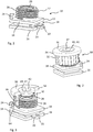
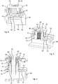
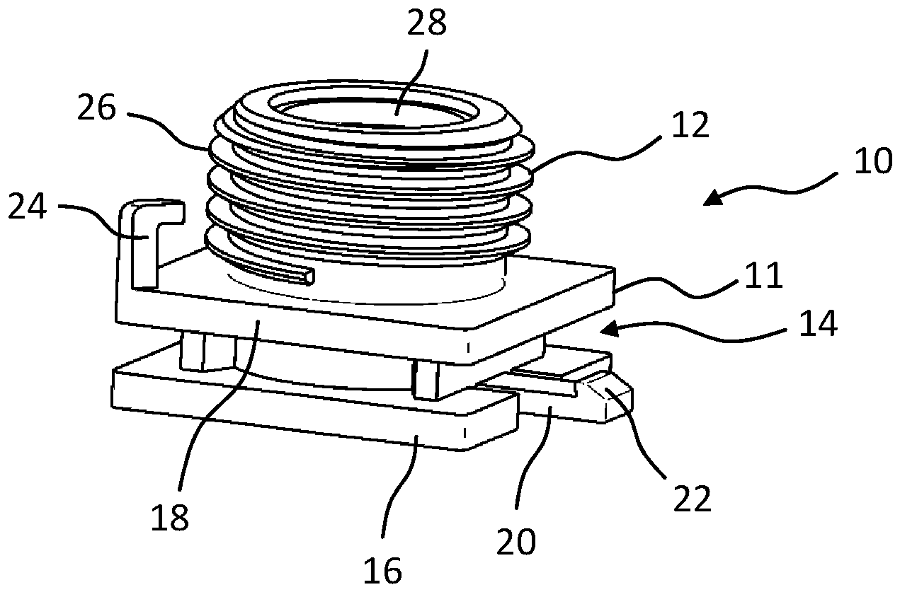
-
1 ein Gewindeteil eines Halteelements eines erfindungsgemäßen Systems in einer perspektivischen Ansicht, -
2 das Gewindeteil aus1 mit einem mit diesem verschraubten Distanzteil des Halteelements in einer perspektivischen Ansicht, -
3 eine teilgeschnittene perspektivische Darstellung des in2 gezeigten Gewindeteils und Distanzteils, -
4 das in2 gezeigte Gewindeteil und Distanzteil im an einem Anbauteil gehaltenen Zustand in einer perspektivischen Ansicht, -
5 eine teilgeschnittene perspektivische Ansicht des in4 gezeigten Gewindeteils, Distanzteils und Anbauteils, und -
6 eine Schnittansicht des in4 gezeigten Gewindeteils, Distanzteils und Anbauteils im an einem Trägerteil befestigten Zustand.
-
1 a threaded part of a holding element of a system according to the invention in a perspective view, -
2 the threaded part1 with a screwed with this spacer part of the holding element in a perspective view, -
3 a partially cutaway perspective view of the in2 shown threaded part and spacer, -
4 this in2 shown thread part and spacer in the held on an attachment state in a perspective view, -
5 a partially cutaway perspective view of the in4 shown threaded part, spacer and attachment, and -
6 a sectional view of the in4 shown threaded part, spacer and attachment in the attached to a support member state.
Soweit nichts anderes angegeben ist, bezeichnen in den Figuren gleiche Bezugszeichen gleiche Gegenstände.Unless otherwise indicated, like reference characters designate like items throughout the figures.
Das in
Das Halteelement des erfindungsgemäßen Systems umfasst darüber hinaus ein Distanzteil
Durch Aufschrauben oder Abschrauben des Distanzteils
In den
Zum Halten des Anbauteils
In dem in
An der Außenseite des Gewindeabschnitts
BezugszeichenlisteLIST OF REFERENCE NUMBERS
- 1010
- Gewindeteilthreaded part
- 1111
- Halteabschnittholding section
- 1212
- Gewindeabschnittthreaded portion
- 1414
- Halteaufnahmeholding receptacle
- 1616
- Erste GrundplatteFirst base plate
- 1818
- Zweite GrundplatteSecond base plate
- 2020
- Rastarmdetent arm
- 2222
- Rasthakenlatch hook
- 2424
- Anschlagarmstop arm
- 2626
- Außengewindeexternal thread
- 2828
- Innengewindeinner thread
- 3030
- Distanzteilspacer
- 3232
- Gewindeabschnittthreaded portion
- 3434
- Kopfabschnittheader
- 3636
- Kontaktflächecontact area
- 3838
- Innengewindeinner thread
- 4040
- Einsatz, AnlageelementInsert, contact element
- 4141
- Anlageflächecontact surface
- 4242
- Klemmabschnittclamping section
- 4444
- Anbauteilattachment
- 4646
- Wandabschnittwall section
- 48, 5048, 50
- Enden des C-förmigen WandabschnittsEnds of the C-shaped wall section
- 5252
- Rastausnehmungrecess
- 5454
- Trägerteilsupport part
- 5656
- DurchgangsöffnungThrough opening
- 5858
- Halteschrauberetention screw
- 6060
- Schraubenkopfscrew head
- 6262
- Unterlegscheibewasher
- 6464
- Radiale ErhebungRadial survey
ZITATE ENTHALTEN IN DER BESCHREIBUNG QUOTES INCLUDE IN THE DESCRIPTION
Diese Liste der vom Anmelder aufgeführten Dokumente wurde automatisiert erzeugt und ist ausschließlich zur besseren Information des Lesers aufgenommen. Die Liste ist nicht Bestandteil der deutschen Patent- bzw. Gebrauchsmusteranmeldung. Das DPMA übernimmt keinerlei Haftung für etwaige Fehler oder Auslassungen.This list of the documents listed by the applicant has been generated automatically and is included solely for the better information of the reader. The list is not part of the German patent or utility model application. The DPMA assumes no liability for any errors or omissions.
Zitierte PatentliteraturCited patent literature
- EP 0840021 A1 [0003]EP 0840021 A1 [0003]
- US 5492388 A [0003]US 5492388 A [0003]
- WO 2016/126284 A1 [0004]WO 2016/126284 A1 [0004]
Claims (13)
Applications Claiming Priority (4)
| Application Number | Priority Date | Filing Date | Title |
|---|---|---|---|
| DE102017108000.7 | 2017-04-13 | ||
| DE102017108000 | 2017-04-13 | ||
| DE102018107595 | 2018-03-29 | ||
| DE102018107595.2 | 2018-03-29 |
Publications (1)
| Publication Number | Publication Date |
|---|---|
| DE102018108829A1 true DE102018108829A1 (en) | 2018-10-18 |
Family
ID=63678909
Family Applications (2)
| Application Number | Title | Priority Date | Filing Date |
|---|---|---|---|
| DE102018108830.2A Pending DE102018108830A1 (en) | 2017-04-13 | 2018-04-13 | System of an attachment and a holding element |
| DE102018108829.9A Pending DE102018108829A1 (en) | 2017-04-13 | 2018-04-13 | retaining element |
Family Applications Before (1)
| Application Number | Title | Priority Date | Filing Date |
|---|---|---|---|
| DE102018108830.2A Pending DE102018108830A1 (en) | 2017-04-13 | 2018-04-13 | System of an attachment and a holding element |
Country Status (1)
| Country | Link |
|---|---|
| DE (2) | DE102018108830A1 (en) |
Cited By (4)
| Publication number | Priority date | Publication date | Assignee | Title |
|---|---|---|---|---|
| CN112443556A (en) * | 2019-09-05 | 2021-03-05 | 伊利诺斯工具制品有限公司 | Spacer assembly |
| DE102021100676A1 (en) | 2020-01-14 | 2021-07-15 | Illinois Tool Works Inc. | Retaining element for attaching an attachment |
| DE102021118920A1 (en) | 2020-08-13 | 2022-02-17 | Illinois Tool Works Inc. | tolerance compensation device |
| DE102024123741A1 (en) | 2023-08-24 | 2025-02-27 | Illinois Tool Works Inc. | tolerance compensation element |
Families Citing this family (4)
| Publication number | Priority date | Publication date | Assignee | Title |
|---|---|---|---|---|
| DE102019110701A1 (en) | 2019-04-25 | 2020-10-29 | Bayerische Motoren Werke Aktiengesellschaft | HOLDING ELEMENT FOR HOLDING A COMPONENT TO BE FIXED AND A HOLDING SYSTEM WITH SUCH |
| DE102019114008A1 (en) * | 2019-05-24 | 2020-11-26 | Bayerische Motoren Werke Aktiengesellschaft | Tolerance compensation fastening system with improved functionality |
| CN114109999B (en) | 2020-08-31 | 2026-03-17 | 伊利诺斯工具制品有限公司 | Nut Fastener Assembly |
| DE102021205411A1 (en) * | 2021-05-27 | 2022-12-01 | Witte Automotive Gmbh | Device for compensating for tolerances between two components to be connected |
Citations (3)
| Publication number | Priority date | Publication date | Assignee | Title |
|---|---|---|---|---|
| US5492388A (en) | 1992-12-28 | 1996-02-20 | Nissan Motor Co., Ltd. | Structure for steering member |
| EP0840021A1 (en) | 1996-11-05 | 1998-05-06 | Jörg Schwarzbich | Device for connecting assembling elements |
| WO2016126284A1 (en) | 2015-02-02 | 2016-08-11 | Illinois Tool Works Inc. | Spacer nut |
-
2018
- 2018-04-13 DE DE102018108830.2A patent/DE102018108830A1/en active Pending
- 2018-04-13 DE DE102018108829.9A patent/DE102018108829A1/en active Pending
Patent Citations (3)
| Publication number | Priority date | Publication date | Assignee | Title |
|---|---|---|---|---|
| US5492388A (en) | 1992-12-28 | 1996-02-20 | Nissan Motor Co., Ltd. | Structure for steering member |
| EP0840021A1 (en) | 1996-11-05 | 1998-05-06 | Jörg Schwarzbich | Device for connecting assembling elements |
| WO2016126284A1 (en) | 2015-02-02 | 2016-08-11 | Illinois Tool Works Inc. | Spacer nut |
Cited By (5)
| Publication number | Priority date | Publication date | Assignee | Title |
|---|---|---|---|---|
| CN112443556A (en) * | 2019-09-05 | 2021-03-05 | 伊利诺斯工具制品有限公司 | Spacer assembly |
| DE102021100676A1 (en) | 2020-01-14 | 2021-07-15 | Illinois Tool Works Inc. | Retaining element for attaching an attachment |
| DE102021118920A1 (en) | 2020-08-13 | 2022-02-17 | Illinois Tool Works Inc. | tolerance compensation device |
| US11560912B2 (en) | 2020-08-13 | 2023-01-24 | Illinois Tool Works Inc. | Tolerance compensation device |
| DE102024123741A1 (en) | 2023-08-24 | 2025-02-27 | Illinois Tool Works Inc. | tolerance compensation element |
Also Published As
| Publication number | Publication date |
|---|---|
| DE102018108830A1 (en) | 2018-10-18 |
Similar Documents
| Publication | Publication Date | Title |
|---|---|---|
| DE102018108829A1 (en) | retaining element | |
| EP1626185B1 (en) | Adjusting unit for adjusting the distance between two construction units | |
| EP1979634B1 (en) | Mounting unit for the fastening eyelet of a belt buckle | |
| DE102017117002A1 (en) | Device for fastening a component to a carrier component | |
| DE102011001052A1 (en) | Fastening device with tolerance compensation | |
| DE202005010873U1 (en) | Tolerance equalizing unit for automatic equalizing of tolerances in the distance between two structural components and is cost effective to produce | |
| DE102010024870A1 (en) | Device for fastening a component to a fastening bolt | |
| DE102018201496A1 (en) | Tolerance compensation device and method for producing a tolerance compensation device | |
| DE102014221266A1 (en) | Quick fastener, method for joining two components by means of the quick fastener and manufacturing method therefor | |
| DE202008002633U1 (en) | Mounting arrangement with automatic three-dimensional tolerance compensation | |
| DE102021100676A1 (en) | Retaining element for attaching an attachment | |
| DE102014103535A1 (en) | Device for fastening a component to a carrier component | |
| DE102016109499A1 (en) | System of a component and a fastening device | |
| WO2020200776A1 (en) | Multipart adjustment element for a tolerance compensation assembly | |
| DE102022129440A1 (en) | Fastening device and method for fastening components to bolts | |
| DE102017108335A1 (en) | Mounting arrangement and a corresponding cabinet housing | |
| EP2161185A1 (en) | Device for fastening a stay to a mudguard | |
| EP3581811A1 (en) | System for attaching a first component to a second component | |
| DE102012022239A1 (en) | Component for attachment to a carrier component of an automobile | |
| DE102019206750B4 (en) | Device for compensating tolerances between a first component and a second component | |
| DE102009018781B4 (en) | joint assembly | |
| DE102004048436A1 (en) | Sleeve for securing bolts in bores has flexible hooks on its outside which lock it into bore and resilient arm which projects into sleeve and locks bolt in position | |
| DE602004000592T2 (en) | Connecting device for a control cable end | |
| DE102019100396A1 (en) | Fastening device for fastening a handle support to a motor vehicle body panel | |
| DE102017129954A1 (en) | Fastening system for fastening a component to a vehicle body |
Legal Events
| Date | Code | Title | Description |
|---|---|---|---|
| R082 | Change of representative |
Representative=s name: MEISSNER BOLTE PATENTANWAELTE RECHTSANWAELTE P, DE Representative=s name: HGF EUROPE LLP, DE Representative=s name: HGF EUROPE LP, DE |
|
| R082 | Change of representative |
Representative=s name: HGF EUROPE LLP, DE Representative=s name: HGF EUROPE LP, DE |
|
| R012 | Request for examination validly filed | ||
| R016 | Response to examination communication |