DE102018108381A1 - Muscle force drive and device with a muscle power drive - Google Patents
Muscle force drive and device with a muscle power drive Download PDFInfo
- Publication number
- DE102018108381A1 DE102018108381A1 DE102018108381.5A DE102018108381A DE102018108381A1 DE 102018108381 A1 DE102018108381 A1 DE 102018108381A1 DE 102018108381 A DE102018108381 A DE 102018108381A DE 102018108381 A1 DE102018108381 A1 DE 102018108381A1
- Authority
- DE
- Germany
- Prior art keywords
- receiving tray
- drive
- rotation
- receiving
- drive lever
- Prior art date
- Legal status (The legal status is an assumption and is not a legal conclusion. Google has not performed a legal analysis and makes no representation as to the accuracy of the status listed.)
- Ceased
Links
Images


Classifications
-
- B—PERFORMING OPERATIONS; TRANSPORTING
- B62—LAND VEHICLES FOR TRAVELLING OTHERWISE THAN ON RAILS
- B62M—RIDER PROPULSION OF WHEELED VEHICLES OR SLEDGES; POWERED PROPULSION OF SLEDGES OR SINGLE-TRACK CYCLES; TRANSMISSIONS SPECIALLY ADAPTED FOR SUCH VEHICLES
- B62M1/00—Rider propulsion of wheeled vehicles
- B62M1/24—Rider propulsion of wheeled vehicles with reciprocating levers, e.g. foot levers
-
- B—PERFORMING OPERATIONS; TRANSPORTING
- B62—LAND VEHICLES FOR TRAVELLING OTHERWISE THAN ON RAILS
- B62J—CYCLE SADDLES OR SEATS; AUXILIARY DEVICES OR ACCESSORIES SPECIALLY ADAPTED TO CYCLES AND NOT OTHERWISE PROVIDED FOR, e.g. ARTICLE CARRIERS OR CYCLE PROTECTORS
- B62J1/00—Saddles or other seats for cycles; Arrangement thereof; Component parts
- B62J1/005—Saddles having a seating area with multiple separate weight bearing surfaces
-
- B—PERFORMING OPERATIONS; TRANSPORTING
- B62—LAND VEHICLES FOR TRAVELLING OTHERWISE THAN ON RAILS
- B62M—RIDER PROPULSION OF WHEELED VEHICLES OR SLEDGES; POWERED PROPULSION OF SLEDGES OR SINGLE-TRACK CYCLES; TRANSMISSIONS SPECIALLY ADAPTED FOR SUCH VEHICLES
- B62M1/00—Rider propulsion of wheeled vehicles
- B62M1/18—Rider propulsion of wheeled vehicles by movement of rider's saddle
Landscapes
- Engineering & Computer Science (AREA)
- Mechanical Engineering (AREA)
- Chemical & Material Sciences (AREA)
- Combustion & Propulsion (AREA)
- Transportation (AREA)
- Rehabilitation Tools (AREA)
Abstract
Ein Muskelkraftantrieb (2, 22) weist einen ersten Antriebshebel (5, 23) auf, der eine erste Aufnahmeschale (7, 26) konkaven Querschnitts aufweist und der an einem ersten Lager (6) um eine Drehachse (11) drehbar gelagert ist. Ferner weist der Muskelkraftantrieb (2, 22) einen zum ersten Antriebshebel (5, 23) im Gegentakt beweglichen zweiten Antriebshebel (8, 24) auf, der eine zweite Aufnahmeschale (10, 29) konkaven Querschnitts aufweist und der an einem zweiten Lager (9) um die Drehachse (11) drehbar gelagert ist. Beide Aufnahmeschalen (7, 26; 10, 29) sind bezüglich eines Drehsinns um die Drehachse (11) gleich orientiert. Das erste Lager (6) und das zweite Lager (9) begrenzen ein lichtes Maß und bei Projektion der Aufnahmeschalen (7, 26; 10; 29) auf eine zum lichten Maß im Wesentlichen parallele Gerade ist eine entlang der Geraden gemessene größte Entfernung zwischen voneinander abgewandten Seiten der ersten Aufnahmeschale (7, 26) und der zweiten Aufnahmeschale (10, 29) höchstens gleich dem lichten Maß.

Description
Die vorliegende Erfindung betrifft einen Muskelkraftantrieb, und insbesondere einen Muskelkraftantrieb für den Beinbetrieb bzw. einen beinbetriebenen Muskelkraftantrieb, mit einem ersten Antriebshebel, der eine erste Aufnahmeschale konkaven Querschnitts aufweist und der an einem ersten Lager um eine Drehachse drehbar gelagert ist, und einem zum ersten Antriebshebel im Gegentakt beweglichen zweiten Antriebshebel, der eine zweite Aufnahmeschale konkaven Querschnitts aufweist und der an einem zweiten Lager um die Drehachse drehbar gelagert ist. Beide Aufnahmeschalen sind bezüglich eines Drehsinns um die Drehachse gleich orientiert.The present invention relates to a muscular power drive, and more particularly to a leg-powered muscle power drive, having a first drive lever having a first receiving cup of concave cross section and rotatably supported at a first bearing about an axis of rotation and one to the first drive lever push-pull movable second drive lever, which has a second receiving tray of concave cross-section and which is rotatably mounted on a second bearing about the axis of rotation. Both receiving shells are oriented the same with respect to a direction of rotation about the axis of rotation.
Bekanntlich versteht man unter einem manuellen Antrieb oder auch Muskelkraftantrieb einen Antrieb für ein Werkzeug, eine Maschine, ein Fahrzeug oder eine sonstige technische Einrichtung mittels Muskelkraft. Gelegentlich spricht man auch von Muskelkraftbetrieb, so zum Beispiel bei muskelkraftbetriebenen Fahrzeugen, wobei als muskelkraftbetriebene Fahrzeuge alle Arten von Fahrzeugen aufgefasst werden, die rein durch Nutzung der Muskelkraft bewegt werden, welche von Fahrern der muskelkraftbetriebenen Fahrzeuge aufgebracht wird, und die nicht durch Maschinen oder äußere Kräfte wie beispielsweise Wind angetrieben werden.As is known, a manual drive or even a power drive means a drive for a tool, a machine, a vehicle or another technical device by means of muscle power. Occasionally one also speaks of muscle power operation, for example in muscle-powered vehicles, where muscle-powered vehicles are understood to be all types of vehicles that are moved purely by the use of the muscular force applied by drivers of the muscle-powered vehicles and not by machines or external Forces such as wind are driven.
Ein bekanntes Beispiel für ein muskelkraftbetriebenes Fahrzeug bzw. für ein Fahrzeug mit Muskelkraftantrieb ist das Fahrrad. Fahrräder weisen im Allgemeinen starr konstruierte Fahrradsättel auf, die sich in erster Linie durch ihre Polsterung und ihre Ausformung unterscheiden, um Druckstellen oder Schmerzen beim Fahren zu minimieren.A well-known example of a muscular powered vehicle or a powered vehicle is the bicycle. Bicycles generally have rigidly constructed bicycle saddles that differ primarily by their padding and shape to minimize pressure points or pain when riding.
Beispielsweise ist in der
Ferner sind geteilte Sättel bekannt, beispielsweise aus der
In der
Ferner sind geteilte Sättel mit einer Drehmomentumlenkung in verschiedenen Ausführungen bekannt, allerdings in einer Achsebene der beweglichen Sattelhälften mit einem Sitz für das Gesäß. Die
Des Weiteren ist in der
Schließlich zeigt die
Zusammenfassend sind Sitze bekannter herkömmlicher Muskelkraftantriebe für den Beinbetrieb wie zum Beispiel Fahrradsättel oder auch zweiseitige, bekannte Sattelsysteme meist direkt an der Lastaufnahme des Körpers durch die Beckenknochen einer Bedienperson beteiligt. Sie stellen hier einen mehr oder weniger großen Widerstand im Bewegungsablauf dar, der zu Knochenhautreizungen und ähnlichen Beschwerden führen kann, die mit Schmerzsignalen wahrgenommen werden. Der Verwendung derartiger Muskelkraftantriebe wird dadurch erheblich beeinträchtigt.In summary, seats known conventional muscle power for leg operation such as bicycle saddles or two-sided, known saddle systems are usually directly involved in the load of the body through the pelvic bone of an operator. Here they represent a more or less great resistance in the movement process, which can lead to periosteum irritations and similar complaints, which are perceived with pain signals. The use of such muscle power is significantly affected.
Es ist die Aufgabe der vorliegenden Erfindung, einen Muskelkraftantrieb und eine Vorrichtung mit einem derartigen Muskelkraftantrieb zu schaffen, die bei Betriebspersonen auftretende Druckstellen oder Schmerzen vermeiden.It is the object of the present invention to provide a muscle power drive and a device with such a muscle power drive, which avoid pressure points or pain occurring in operating personnel.
Diese Aufgabe wird durch den Muskelkraftantrieb mit den im Anspruch 1 genannten Merkmalen und die Vorrichtung mit den im Anspruch 6 genannten Merkmalen gelöst. Bevorzugte Ausführungsformen sind Gegenstand der abhängigen Ansprüche.This object is achieved by the muscle power drive with the features mentioned in
Gemäß der vorliegenden Erfindung begrenzen das erste Lager und das zweite Lager ein lichtes Maß und bei Projektion der Aufnahmeschalen auf eine zum lichten Maß im Wesentlichen parallele Gerade ist eine entlang der Geraden gemessene größte Entfernung zwischen voneinander abgewandten Seiten der ersten Aufnahmeschale und der zweiten Aufnahmeschale höchstens gleich dem lichten Maß bzw. kleiner als das lichte Maß. Als lichtes Maß, auch Lichtmaß oder Lichte oder Öffnungsmaß genannt, bezeichnet man im Allgemeinen die Breite oder Höhe eines Hohlraums oder eines Raumes, beziehungsweise den freien Abstand zwischen angrenzenden Bauteilen oder begrenzenden Hüllflächen. Folglich bezeichnet ein vom ersten Lager und vom zweiten Lager begrenztes lichtes Maß einen freien Abstand oder gegenstandsfreien Abstand oder einen Raum oder Freiraum zwischen dem ersten Lager und dem zweiten Lager. Anders ausgedrückt ist der Abstand oder Raum zwischen dem ersten Lager und dem zweiten Lager unverstellt oder hindernisfrei bzw. zwischen dem ersten Lager und dem zweiten Lager ist kein Hindernis oder Gegenstand vorhanden. Weil zudem das lichte Maß wenigstens gleich oder größer ist als die größte Entfernung zwischen voneinander abgewandten Seiten der ersten Aufnahmeschale und der zweiten Aufnahmeschale bei Projektion derselben auf eine zum lichten Maß parallele Gerade, schwebt das Gesäß einer den Muskelkraftantrieb betätigenden Person, deren jeweilige Oberschenkel in der ersten und der zweiten Aufnahmeschale aufgenommen sind, frei in der Luft. Mit anderen Worten ist der Muskelkraftantrieb derart ausgebildet, dass das Gesäß einer Bedienperson, deren jeweilige Oberschenkel in der ersten und der zweiten Aufnahmeschale aufgenommen sind bzw. deren linker Oberschenkel in der ersten Aufnahmeschale aufgenommen ist und deren rechter Oberschenkel in der zweiten Aufnahmeschale aufgenommen ist, frei in der Luft schwebt. Beispielsweise kann das Gesäß dabei zwischen dem ersten und dem zweiten Lager bzw. in einem Raum zwischen der ersten und zweiten Aufnahmeschale und dem ersten und zweiten Lager positioniert sein.According to the present invention, the first bearing and the second bearing limit a light measure and projection of the receiving shells to a straight line substantially parallel straight line measured along the straightest distance between opposite sides of the first receiving tray and the second receiving tray is at most equal the clear dimension or smaller than the clear dimension. As a light measure, also called Lichtmaß or light or opening dimension, called generally the Width or height of a cavity or space, or the free distance between adjacent components or limiting envelope surfaces. Thus, a light amount defined by the first bearing and the second bearing means a free distance or pitch or a space or clearance between the first bearing and the second bearing. In other words, the distance or space between the first bearing and the second bearing is undisturbed or free of obstacles, or there is no obstacle or object between the first bearing and the second bearing. In addition, because the clear dimension is at least equal to or greater than the maximum distance between facing away from each other sides of the first receiving tray and the second receiving tray when projecting the same on a straight line parallel to parallel dimension, floats the buttocks of a person operating the muscle power drive, their respective thighs in the first and second receiving tray are included, free in the air. In other words, the power drive is designed such that the buttocks of an operator whose respective thighs are accommodated in the first and the second receiving tray or whose left thigh is received in the first receiving tray and the right thigh is received in the second receiving tray, free floating in the air. For example, the buttocks can be positioned between the first and the second bearing or in a space between the first and second receiving tray and the first and second bearing.
Beim erfindungsgemäßen Muskelkraftantrieb werden somit die Beckenknochen und das Hinterteil als Auflagefläche ausgespart und es treten auch keine Berührungspunkte mit den Hoden oder dem Dammbereich auf. Für diese Körperbereiche wird vielmehr eine Lastübertragung ausgespart. Stattdessen wird dem abwechselnd Gewicht übertragenden Körperteil, also im Wechsel dem linken und rechten Oberschenkel, eine optimale Unterstützung und Lagerung ermöglicht. Da der erste und der zweite Antriebshebel im Gegentakt beweglich sind, wird durch die Kraftausübung eines Oberschenkels, der denjenigen Antriebshebel nach unten drückt, in dessen Aufnahmeschale er aufgenommen ist, in gleichem Maße durch eine Drehmomentübertragung von einer Seite zur anderen der jeweilige andere Antriebshebel entsprechend nach oben gedrückt. Zudem ist beim Muskelkraftantrieb der vorliegenden Erfindung ein Scheuern oder Rutschen der empfindlichen Körperteile, das bei allen bekannten Sattelkonzepten nicht gänzlich vermieden werden kann, konstruktionsbedingt ausgeschlossen.When muscle power drive according to the invention thus the pelvic bone and the hindquarters are recessed as a support surface and there are no points of contact with the testicles or the perineal area. For these body areas rather a load transfer is omitted. Instead, the alternately weight-transmitting body part, ie alternately the left and right thigh, optimal support and storage is possible. Since the first and the second drive lever are movable in push-pull, by the exercise of a thigh, which pushes those drive lever down, in the receiving tray he is taken to the same extent by a torque transmission from one side to the other of the respective other drive lever according to pressed up. In addition, in the muscle power of the present invention, a chafing or slipping of the sensitive body parts, which can not be completely avoided in all known saddle concepts, due to the design excluded.
Bei einer bevorzugten Ausführungsform eines Muskelkraftantriebs sind jeweilige Linien, die durch Scheitelpunkte der jeweiligen Querschnitte an jeweiligen der Drehachse zugewandten Enden und an jeweiligen von der Drehachse abgewandten Enden der jeweiligen Aufnahmeschalen verlaufen, zur Drehachse windschief orientiert. Mit einem derartigen Muskelkraftantrieb ist es möglich, eine durch Drehpunkte der Oberschenkel einer Bedienperson des Muskelkraftantriebs verlaufende Beindrehachse mit der Drehachse in Deckung zu bringen. Hierbei befindet sich das Becken der Bedienperson zwischen dem ersten und dem zweiten Lager angeordnet, also innerhalb des von diesen beiden Lagern begrenzten lichten Maßes. Da sich in einem solchen Fall die Antriebshebel und die Oberschenkel um dieselbe Drehachse drehen, sind die Oberschenkel und die Aufnahmeschalen in jeder Phase der Auf- und Abwärtsbewegung deckungsgleich und es findet kein Verschieben der Oberschenkel innerhalb der Aufnahmeschalen statt.In a preferred embodiment of a muscle power drive, respective lines that run through vertexes of the respective cross sections at respective ends facing the axis of rotation and at respective ends of the respective receiving shells facing away from the axis of rotation are oriented skewed with respect to the axis of rotation. With such a muscle power drive, it is possible to bring a pivoting axis of rotation of the thighs of an operator of the muscle power drive Beindrehachse with the axis of rotation in coincidence. Here, the pelvis of the operator is disposed between the first and the second bearing, ie within the limited by these two camps clear measure. Since, in such a case, the drive levers and the thighs rotate about the same axis of rotation, the thighs and the receiving cups are congruent at each stage of the up and down movement and there is no displacement of the thighs within the receiving cups.
Vorteilhafterweise ist die erste Aufnahmeschale dazu eingerichtet, verschiedene Positionen und/oder verschiedene Orientierungen am ersten Antriebshebel einzunehmen und/oder die zweite Aufnahmeschale ist dazu eingerichtet, verschiedene Positionen und/oder verschiedene Orientierungen am zweiten Antriebshebel einzunehmen oder die erste Aufnahmeschale ist bezüglich des ersten Antriebshebels fixiert und/oder die zweite Aufnahmeschale ist bezüglich des zweiten Antriebshebels fixiert. Bei einem derartig ausgebildeten Muskelkraftantrieb ist eine Einstellung der Aufnahmeschalen nach ergonomischen Gesichtspunkten möglich, was die Betätigung des Muskelkraftantriebs weiter erleichtert. Ferner kann der Muskelkraftantrieb vorteilhaft wenigstens einen Kippmechanismus oder wenigstens eine Schienenführung für die erste Aufnahmeschale und/oder für die zweite Aufnahmeschale aufweisen. Der Kippmechanismus, der insbesondere eine Drehmomentumlenkung bewirken kann, kann beispielsweise drei Kegelräder oder ein Planetengetriebe aufweisen. Mittels derartiger Einrichtungen kann sichergestellt werden, dass eventuelle Ungleichmäßigkeiten bei der Bewegung der Antriebshebel und der in den Aufnahmeschalen aufgenommenen Oberschenkel ausgeglichen werden und die Oberschenkel innerhalb der Aufnahmeschalen nicht verrutschen. Hingegen sind bezüglich des jeweiligen Antriebshebels fixierte Aufnahmeschalen relativ zum Antriebshebel weder verkippbar noch verschiebbar, das heißt dass sowohl deren Orientierung zum Antriebshebel als auch deren Position am Antriebshebel fixiert oder unveränderlich ist.Advantageously, the first receiving tray is adapted to occupy different positions and / or different orientations on the first drive lever and / or the second receiving tray is adapted to occupy different positions and / or different orientations on the second drive lever or the first receiving tray is fixed relative to the first drive lever and / or the second receiving tray is fixed with respect to the second drive lever. In such a trained muscle power drive adjustment of the receiving shells after ergonomic considerations is possible, which further facilitates the operation of the muscle power drive. Furthermore, the muscle power drive may advantageously have at least one tilting mechanism or at least one rail guide for the first receiving tray and / or for the second receiving tray. The tilting mechanism, which can in particular cause a torque deflection, can for example have three bevel gears or a planetary gear. By means of such devices it can be ensured that any irregularities in the movement of the drive lever and the thighs received in the receiving shells are compensated and the thighs do not slip within the receiving shells. By contrast, with respect to the respective drive lever fixed receiving shells are neither tiltable nor displaceable relative to the drive lever, that is that both their orientation to the drive lever and its position fixed to the drive lever or fixed.
Vorzugsweise ist die erste Aufnahmeschale und/oder die zweite Aufnahmeschale wenigstens teilweise oder vollständig aus Kunststoff oder Kohlenstoff bzw. Carbon hergestellt oder mit Kunststoff oder Kohlenstoff bzw. Carbon beschichtet. Solcherart beschichtete Aufnahmeschalen weisen insbesondere einen geringen Reibungswert auf, so dass bei derartigen Aufnahmeschalen ein Verrutschen der Oberschenkel innerhalb der Aufnahmeschalen in Kauf genommen werden kann. Zudem können die Aufnahmeschalen mit einer Polsterung ausgestattet sein.Preferably, the first receiving tray and / or the second receiving tray is at least partially or completely made of plastic or carbon or carbon or coated with plastic or carbon or carbon. In particular, such coated receiving trays have a low coefficient of friction, so that at such receiving shells slipping of the thighs within the receiving trays can be accepted. In addition, the receiving trays can be equipped with a padding.
Bei einer Vorrichtung mit wenigstens einem Muskelkraftantrieb kann es sich ganz Allgemein um ein Fahrzeug oder ein Sportgerät oder ein Werkzeug oder eine Maschine handelt. So kann beispielsweise ein Fahrrad oder ein sogenanntes Spinning-Bike einen derartigen Muskelkraftantrieb aufweisen.In a device with at least one manual power drive, it can be very generally a vehicle or a sports device or a tool or a machine. For example, a bicycle or a so-called spinning bike may have such a muscle power drive.
Die Vorrichtung kann vorzugsweise einen Rahmen aufweisen, an dem der Muskelkraftantrieb lösbar oder fest angeordnet ist. Je nach Bedarf kann der Muskelkraftantrieb von derartigen Vorrichtungen entfernt und zum Beispiel durch einen anderen Muskelkraftantrieb ersetzt werden.The device may preferably have a frame on which the muscle power drive is detachably or firmly arranged. As needed, the muscular drive can be removed from such devices and replaced, for example, by another muscle drive.
Vorteilhaft weist die Vorrichtung wenigstens einen Stromspeicher und/oder wenigstens einen Elektromotor und/oder wenigstens eine Stromerzeugungseinrichtung auf. Handelt es sich bei der Vorrichtung beispielsweise um ein E-Bike, so kann die von der Betriebsperson aufgewendete Bewegungsenergie in elektrischen Strom zur Speisung des Stromspeichers oder der Batterie umgewandelt werden. Ferner kann der Elektromotor eines E-Bikes mit einem Getriebe zur Bewegung der Antriebshebel genutzt werden.Advantageously, the device has at least one power store and / or at least one electric motor and / or at least one power generating device. For example, if the device is an e-bike, the kinetic energy spent by the operator may be converted to electrical power to power the power storage or battery. Furthermore, the electric motor of an e-bike can be used with a transmission for moving the drive lever.
Die Erfindung wird nachfolgend anhand bevorzugter Ausführungsbeispiele unter Zuhilfenahme von Figuren näher erläutert. Es zeigen:
-
1 eine Draufsicht auf einen Teil eines Fahrrades mit einem Muskelkraftantrieb; -
2 eine Seitenansicht des Fahrrades aus der1 ; -
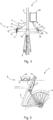
3 eine Detailansicht des Muskelkraftantriebs; -
4 die Seitenansicht der2 mit Bedienperson; -
5 einen Muskelkraftantrieb mit beweglichen Aufnahmeschalen.
-
1 a plan view of a part of a bicycle with a manual power drive; -
2 a side view of the bike from the1 ; -
3 a detailed view of the muscle power drive; -
4 the side view of2 with operator; -
5 a muscle power drive with movable receiving shells.
In der
Der Muskelkraftantrieb
Die Bewegungen des ersten Antriebshebels
Wie in der Detailansicht der
Beide Aufnahmeschalen
Beim Fahren des Fahrrades
In der
Um dem Fahrer
Beim Muskelkraftantrieb
Insbesondere erleichtert es die Beweglichkeit der beiden Aufnahmeschalen
Bezugszeichenliste LIST OF REFERENCE NUMBERS
- 1.1.
- Fahrradbicycle
- 2.Second
- MuskelkraftantriebMuscle power drive
- 3.Third
- Rahmenframe
- 4.4th
- Hinterradrear wheel
- 5.5th
- erster Antriebshebelfirst drive lever
- 6.6th
- erstes Lagerfirst camp
- 7.7th
- erste Aufnahmeschalefirst receiving tray
- 8.8th.
- zweiter Antriebshebelsecond drive lever
- 9.9th
- zweites Lagersecond camp
- 10.10th
- zweite Aufnahmeschalesecond receiving tray
- 11.11th
- Drehachseaxis of rotation
- 12.12th
- Wellewave
- 13.13th
- erstes Ritzelfirst pinion
- 14.14th
- zweites Ritzelsecond pinion
- 15.15th
- erste Kettefirst chain
- 16.16th
- drittes Ritzelthird pinion
- 17.17th
- viertes Ritzelfourth pinion
- 18.18th
- erstes Zahnradfirst gear
- 19.19th
- zweites Zahnradsecond gear
- 20.20th
- zweite Kettesecond chain
- 21.21st
- Fahrerdriver
- 22.22nd
- MuskelkraftantriebMuscle power drive
- 23.23rd
- erster Antriebshebelfirst drive lever
- 24.24th
- zweiter Antriebshebelsecond drive lever
- 25.25th
- erster Hebelarmfirst lever arm
- 26.26th
- erste Aufnahmeschalefirst receiving tray
- 27.27th
- erster Kippmechanismusfirst tilting mechanism
- 28.28th
- zweiter Hebelarmsecond lever arm
- 29.29th
- zweite Aufnahmeschalesecond receiving tray
- 30.30th
- zweiter Kippmechanismussecond tilting mechanism
- 31.31st
- erste Schienenführungfirst rail guide
- 32.32nd
- zweite Schienenführungsecond rail guide
ZITATE ENTHALTEN IN DER BESCHREIBUNG QUOTES INCLUDE IN THE DESCRIPTION
Diese Liste der vom Anmelder aufgeführten Dokumente wurde automatisiert erzeugt und ist ausschließlich zur besseren Information des Lesers aufgenommen. Die Liste ist nicht Bestandteil der deutschen Patent- bzw. Gebrauchsmusteranmeldung. Das DPMA übernimmt keinerlei Haftung für etwaige Fehler oder Auslassungen.This list of the documents listed by the applicant has been generated automatically and is included solely for the better information of the reader. The list is not part of the German patent or utility model application. The DPMA assumes no liability for any errors or omissions.
Zitierte PatentliteraturCited patent literature
- DE 10309352 A1 [0004]DE 10309352 A1 [0004]
- US 5725274 [0004]US 5725274 [0004]
- DE 10215916 A1 [0005]DE 10215916 A1 [0005]
- US 6142562 A1 [0006]US 6142562 A1 [0006]
- US 4089559 [0007]US 4089559 [0007]
- KR 1020110017084 A [0008]KR 1020110017084 A [0008]
- DE 102004048424 A1 [0009]DE 102004048424 A1 [0009]
Claims (8)
Priority Applications (2)
| Application Number | Priority Date | Filing Date | Title |
|---|---|---|---|
| DE102018108381.5A DE102018108381A1 (en) | 2018-04-09 | 2018-04-09 | Muscle force drive and device with a muscle power drive |
| EP19167452.2A EP3552942A1 (en) | 2018-04-09 | 2019-04-04 | Muscle power drive and device comprising a muscle power drive |
Applications Claiming Priority (1)
| Application Number | Priority Date | Filing Date | Title |
|---|---|---|---|
| DE102018108381.5A DE102018108381A1 (en) | 2018-04-09 | 2018-04-09 | Muscle force drive and device with a muscle power drive |
Publications (1)
| Publication Number | Publication Date |
|---|---|
| DE102018108381A1 true DE102018108381A1 (en) | 2019-10-10 |
Family
ID=66101868
Family Applications (1)
| Application Number | Title | Priority Date | Filing Date |
|---|---|---|---|
| DE102018108381.5A Ceased DE102018108381A1 (en) | 2018-04-09 | 2018-04-09 | Muscle force drive and device with a muscle power drive |
Country Status (2)
| Country | Link |
|---|---|
| EP (1) | EP3552942A1 (en) |
| DE (1) | DE102018108381A1 (en) |
Citations (8)
| Publication number | Priority date | Publication date | Assignee | Title |
|---|---|---|---|---|
| US4089559A (en) | 1976-09-13 | 1978-05-16 | Prange Bernard H | Vehicle seat |
| US5725274A (en) | 1995-03-31 | 1998-03-10 | Bergmeister; Josef | Bicycle seat |
| US6142562A (en) | 1999-01-21 | 2000-11-07 | Varan; Cyrus | Bicycle seat |
| DE10215916A1 (en) | 2002-04-11 | 2003-10-23 | Paul Icking | Comfort saddle for bicycles, fitness appliances, etc. consists of softly padded left and right sections moving up and down with pedal movement, to prevent numbness and skin irritation |
| DE10309352A1 (en) | 2003-03-03 | 2004-09-23 | Hans Scholz | saddle |
| DE102004048424A1 (en) | 2004-10-05 | 2006-04-13 | Bruno Gruber | Saddle for cycle or exercise machine has two thigh supports connected to one another through connecting device for contra vertical swivel movement |
| KR20110017084A (en) | 2009-08-13 | 2011-02-21 | 유현규 | A partition type bicycle saddle structure |
| DE102016012073A1 (en) * | 2016-10-10 | 2018-04-12 | Axel Kraaz | Saddle arrangement for a pedal-driven device |
Family Cites Families (3)
| Publication number | Priority date | Publication date | Assignee | Title |
|---|---|---|---|---|
| FR2537007A1 (en) * | 1982-12-06 | 1984-06-08 | Levrier Francois | Apparatus for re-education and muscle development of the quadriceps |
| KR20160056739A (en) * | 2014-11-12 | 2016-05-20 | 이경현 | Hip outer shaft type saddle |
| KR101712517B1 (en) * | 2015-02-09 | 2017-03-09 | 대구가톨릭대학교산학협력단 | Bicycle driving apparatus using a thighs |
-
2018
- 2018-04-09 DE DE102018108381.5A patent/DE102018108381A1/en not_active Ceased
-
2019
- 2019-04-04 EP EP19167452.2A patent/EP3552942A1/en not_active Withdrawn
Patent Citations (8)
| Publication number | Priority date | Publication date | Assignee | Title |
|---|---|---|---|---|
| US4089559A (en) | 1976-09-13 | 1978-05-16 | Prange Bernard H | Vehicle seat |
| US5725274A (en) | 1995-03-31 | 1998-03-10 | Bergmeister; Josef | Bicycle seat |
| US6142562A (en) | 1999-01-21 | 2000-11-07 | Varan; Cyrus | Bicycle seat |
| DE10215916A1 (en) | 2002-04-11 | 2003-10-23 | Paul Icking | Comfort saddle for bicycles, fitness appliances, etc. consists of softly padded left and right sections moving up and down with pedal movement, to prevent numbness and skin irritation |
| DE10309352A1 (en) | 2003-03-03 | 2004-09-23 | Hans Scholz | saddle |
| DE102004048424A1 (en) | 2004-10-05 | 2006-04-13 | Bruno Gruber | Saddle for cycle or exercise machine has two thigh supports connected to one another through connecting device for contra vertical swivel movement |
| KR20110017084A (en) | 2009-08-13 | 2011-02-21 | 유현규 | A partition type bicycle saddle structure |
| DE102016012073A1 (en) * | 2016-10-10 | 2018-04-12 | Axel Kraaz | Saddle arrangement for a pedal-driven device |
Also Published As
| Publication number | Publication date |
|---|---|
| EP3552942A1 (en) | 2019-10-16 |
Similar Documents
| Publication | Publication Date | Title |
|---|---|---|
| DE69519943T2 (en) | Wheelchair frame | |
| DE2742719C2 (en) | Exercise bike | |
| EP1454823A2 (en) | Saddle | |
| DE20210395U1 (en) | Magnetic control of a trim wheel | |
| DE102013216826A1 (en) | Two-wheeled vehicle with spring-loaded pinionswing | |
| DE10014531A1 (en) | Adjustable pedal for fitting in motor vehicles and equipment has a pedal tread, a pedal arm with devices for holding connections for operating pull wires and a mounting on a pedal frame with several inter-movable parts. | |
| DE60306178T2 (en) | ADJUSTABLE PEDAL UNIT FOR A MOTOR VEHICLE | |
| DE102020131206A1 (en) | Support device adjustable by electric motor | |
| EP2038161A2 (en) | Steering device and operating method for it | |
| AT507144B1 (en) | A pedal drive | |
| DE102018108381A1 (en) | Muscle force drive and device with a muscle power drive | |
| DE69835019T2 (en) | ROTATABLE VEHICLE SEAT | |
| DE29802643U1 (en) | Locomotion and / or training device | |
| DE602004005147T2 (en) | Adjustable pedal unit for vehicles | |
| DE9003931U1 (en) | Foldable bicycle | |
| DE19801524B4 (en) | Sitting and / or lying furniture | |
| DE10057394B4 (en) | Pedal wheel or scooter | |
| DE102017000144B3 (en) | Bicycle with arm drive | |
| DE3827153C1 (en) | Wheel-chair | |
| DE102011056471B4 (en) | Hand-operated scooter | |
| DE102016012073A1 (en) | Saddle arrangement for a pedal-driven device | |
| EP1604881A1 (en) | Adjustable steering column; method for adjusting a steering column | |
| DE212008000106U1 (en) | Bicycle or exercise bike seat | |
| DE202008007475U1 (en) | Seatpost for a bicycle | |
| DE19502739A1 (en) | Exercise bike with extra drive for therapy use |
Legal Events
| Date | Code | Title | Description |
|---|---|---|---|
| R163 | Identified publications notified | ||
| R012 | Request for examination validly filed | ||
| R002 | Refusal decision in examination/registration proceedings | ||
| R003 | Refusal decision now final |