DE102018108008A1 - Device for compressed air generation for an internal combustion engine with an additional valve - Google Patents
Device for compressed air generation for an internal combustion engine with an additional valve Download PDFInfo
- Publication number
- DE102018108008A1 DE102018108008A1 DE102018108008.5A DE102018108008A DE102018108008A1 DE 102018108008 A1 DE102018108008 A1 DE 102018108008A1 DE 102018108008 A DE102018108008 A DE 102018108008A DE 102018108008 A1 DE102018108008 A1 DE 102018108008A1
- Authority
- DE
- Germany
- Prior art keywords
- valve
- additional
- gas exchange
- additional valve
- cylinder unit
- Prior art date
- Legal status (The legal status is an assumption and is not a legal conclusion. Google has not performed a legal analysis and makes no representation as to the accuracy of the status listed.)
- Withdrawn
Links
Images


Classifications
-
- F—MECHANICAL ENGINEERING; LIGHTING; HEATING; WEAPONS; BLASTING
- F02—COMBUSTION ENGINES; HOT-GAS OR COMBUSTION-PRODUCT ENGINE PLANTS
- F02D—CONTROLLING COMBUSTION ENGINES
- F02D17/00—Controlling engines by cutting out individual cylinders; Rendering engines inoperative or idling
- F02D17/02—Cutting-out
- F02D17/023—Cutting-out the inactive cylinders acting as compressor other than for pumping air into the exhaust system
-
- F—MECHANICAL ENGINEERING; LIGHTING; HEATING; WEAPONS; BLASTING
- F01—MACHINES OR ENGINES IN GENERAL; ENGINE PLANTS IN GENERAL; STEAM ENGINES
- F01L—CYCLICALLY OPERATING VALVES FOR MACHINES OR ENGINES
- F01L1/00—Valve-gear or valve arrangements, e.g. lift-valve gear
- F01L1/12—Transmitting gear between valve drive and valve
- F01L1/18—Rocking arms or levers
- F01L1/181—Centre pivot rocking arms
-
- F—MECHANICAL ENGINEERING; LIGHTING; HEATING; WEAPONS; BLASTING
- F01—MACHINES OR ENGINES IN GENERAL; ENGINE PLANTS IN GENERAL; STEAM ENGINES
- F01L—CYCLICALLY OPERATING VALVES FOR MACHINES OR ENGINES
- F01L1/00—Valve-gear or valve arrangements, e.g. lift-valve gear
- F01L1/26—Valve-gear or valve arrangements, e.g. lift-valve gear characterised by the provision of two or more valves operated simultaneously by same transmitting-gear; peculiar to machines or engines with more than two lift-valves per cylinder
- F01L1/267—Valve-gear or valve arrangements, e.g. lift-valve gear characterised by the provision of two or more valves operated simultaneously by same transmitting-gear; peculiar to machines or engines with more than two lift-valves per cylinder with means for varying the timing or the lift of the valves
-
- F—MECHANICAL ENGINEERING; LIGHTING; HEATING; WEAPONS; BLASTING
- F01—MACHINES OR ENGINES IN GENERAL; ENGINE PLANTS IN GENERAL; STEAM ENGINES
- F01L—CYCLICALLY OPERATING VALVES FOR MACHINES OR ENGINES
- F01L3/00—Lift-valve, i.e. cut-off apparatus with closure members having at least a component of their opening and closing motion perpendicular to the closing faces; Parts or accessories thereof
- F01L3/20—Shapes or constructions of valve members, not provided for in preceding subgroups of this group
-
- F—MECHANICAL ENGINEERING; LIGHTING; HEATING; WEAPONS; BLASTING
- F01—MACHINES OR ENGINES IN GENERAL; ENGINE PLANTS IN GENERAL; STEAM ENGINES
- F01L—CYCLICALLY OPERATING VALVES FOR MACHINES OR ENGINES
- F01L3/00—Lift-valve, i.e. cut-off apparatus with closure members having at least a component of their opening and closing motion perpendicular to the closing faces; Parts or accessories thereof
- F01L3/24—Safety means or accessories, not provided for in preceding sub- groups of this group
-
- F—MECHANICAL ENGINEERING; LIGHTING; HEATING; WEAPONS; BLASTING
- F02—COMBUSTION ENGINES; HOT-GAS OR COMBUSTION-PRODUCT ENGINE PLANTS
- F02B—INTERNAL-COMBUSTION PISTON ENGINES; COMBUSTION ENGINES IN GENERAL
- F02B33/00—Engines characterised by provision of pumps for charging or scavenging
- F02B33/02—Engines with reciprocating-piston pumps; Engines with crankcase pumps
- F02B33/06—Engines with reciprocating-piston pumps; Engines with crankcase pumps with reciprocating-piston pumps other than simple crankcase pumps
- F02B33/22—Engines with reciprocating-piston pumps; Engines with crankcase pumps with reciprocating-piston pumps other than simple crankcase pumps with pumping cylinder situated at side of working cylinder, e.g. the cylinders being parallel
-
- F—MECHANICAL ENGINEERING; LIGHTING; HEATING; WEAPONS; BLASTING
- F02—COMBUSTION ENGINES; HOT-GAS OR COMBUSTION-PRODUCT ENGINE PLANTS
- F02B—INTERNAL-COMBUSTION PISTON ENGINES; COMBUSTION ENGINES IN GENERAL
- F02B33/00—Engines characterised by provision of pumps for charging or scavenging
- F02B33/02—Engines with reciprocating-piston pumps; Engines with crankcase pumps
- F02B33/28—Component parts, details or accessories of crankcase pumps, not provided for in, or of interest apart from, subgroups F02B33/02 - F02B33/26
- F02B33/30—Control of inlet or outlet ports
-
- F—MECHANICAL ENGINEERING; LIGHTING; HEATING; WEAPONS; BLASTING
- F02—COMBUSTION ENGINES; HOT-GAS OR COMBUSTION-PRODUCT ENGINE PLANTS
- F02D—CONTROLLING COMBUSTION ENGINES
- F02D13/00—Controlling the engine output power by varying inlet or exhaust valve operating characteristics, e.g. timing
- F02D13/02—Controlling the engine output power by varying inlet or exhaust valve operating characteristics, e.g. timing during engine operation
- F02D13/0276—Actuation of an additional valve for a special application, e.g. for decompression, exhaust gas recirculation or cylinder scavenging
-
- F—MECHANICAL ENGINEERING; LIGHTING; HEATING; WEAPONS; BLASTING
- F02—COMBUSTION ENGINES; HOT-GAS OR COMBUSTION-PRODUCT ENGINE PLANTS
- F02D—CONTROLLING COMBUSTION ENGINES
- F02D13/00—Controlling the engine output power by varying inlet or exhaust valve operating characteristics, e.g. timing
- F02D13/02—Controlling the engine output power by varying inlet or exhaust valve operating characteristics, e.g. timing during engine operation
- F02D13/06—Cutting-out cylinders
-
- F—MECHANICAL ENGINEERING; LIGHTING; HEATING; WEAPONS; BLASTING
- F01—MACHINES OR ENGINES IN GENERAL; ENGINE PLANTS IN GENERAL; STEAM ENGINES
- F01L—CYCLICALLY OPERATING VALVES FOR MACHINES OR ENGINES
- F01L1/00—Valve-gear or valve arrangements, e.g. lift-valve gear
- F01L1/12—Transmitting gear between valve drive and valve
- F01L1/14—Tappets; Push rods
-
- F—MECHANICAL ENGINEERING; LIGHTING; HEATING; WEAPONS; BLASTING
- F01—MACHINES OR ENGINES IN GENERAL; ENGINE PLANTS IN GENERAL; STEAM ENGINES
- F01L—CYCLICALLY OPERATING VALVES FOR MACHINES OR ENGINES
- F01L1/00—Valve-gear or valve arrangements, e.g. lift-valve gear
- F01L1/12—Transmitting gear between valve drive and valve
- F01L1/18—Rocking arms or levers
- F01L1/185—Overhead end-pivot rocking arms
-
- F—MECHANICAL ENGINEERING; LIGHTING; HEATING; WEAPONS; BLASTING
- F01—MACHINES OR ENGINES IN GENERAL; ENGINE PLANTS IN GENERAL; STEAM ENGINES
- F01L—CYCLICALLY OPERATING VALVES FOR MACHINES OR ENGINES
- F01L1/00—Valve-gear or valve arrangements, e.g. lift-valve gear
- F01L1/46—Component parts, details, or accessories, not provided for in preceding subgroups
- F01L2001/467—Lost motion springs
-
- F—MECHANICAL ENGINEERING; LIGHTING; HEATING; WEAPONS; BLASTING
- F01—MACHINES OR ENGINES IN GENERAL; ENGINE PLANTS IN GENERAL; STEAM ENGINES
- F01L—CYCLICALLY OPERATING VALVES FOR MACHINES OR ENGINES
- F01L13/00—Modifications of valve-gear to facilitate reversing, braking, starting, changing compression ratio, or other specific operations
- F01L13/0015—Modifications of valve-gear to facilitate reversing, braking, starting, changing compression ratio, or other specific operations for optimising engine performances by modifying valve lift according to various working parameters, e.g. rotational speed, load, torque
- F01L2013/0089—Modifications of valve-gear to facilitate reversing, braking, starting, changing compression ratio, or other specific operations for optimising engine performances by modifying valve lift according to various working parameters, e.g. rotational speed, load, torque with means for delaying valve closing
- F01L2013/0094—Modifications of valve-gear to facilitate reversing, braking, starting, changing compression ratio, or other specific operations for optimising engine performances by modifying valve lift according to various working parameters, e.g. rotational speed, load, torque with means for delaying valve closing with switchable clamp for keeping valve open
-
- F—MECHANICAL ENGINEERING; LIGHTING; HEATING; WEAPONS; BLASTING
- F01—MACHINES OR ENGINES IN GENERAL; ENGINE PLANTS IN GENERAL; STEAM ENGINES
- F01L—CYCLICALLY OPERATING VALVES FOR MACHINES OR ENGINES
- F01L23/00—Valves controlled by impact by piston, e.g. in free-piston machines
-
- F—MECHANICAL ENGINEERING; LIGHTING; HEATING; WEAPONS; BLASTING
- F01—MACHINES OR ENGINES IN GENERAL; ENGINE PLANTS IN GENERAL; STEAM ENGINES
- F01L—CYCLICALLY OPERATING VALVES FOR MACHINES OR ENGINES
- F01L2800/00—Methods of operation using a variable valve timing mechanism
- F01L2800/12—Fail safe operation
-
- Y—GENERAL TAGGING OF NEW TECHNOLOGICAL DEVELOPMENTS; GENERAL TAGGING OF CROSS-SECTIONAL TECHNOLOGIES SPANNING OVER SEVERAL SECTIONS OF THE IPC; TECHNICAL SUBJECTS COVERED BY FORMER USPC CROSS-REFERENCE ART COLLECTIONS [XRACs] AND DIGESTS
- Y02—TECHNOLOGIES OR APPLICATIONS FOR MITIGATION OR ADAPTATION AGAINST CLIMATE CHANGE
- Y02T—CLIMATE CHANGE MITIGATION TECHNOLOGIES RELATED TO TRANSPORTATION
- Y02T10/00—Road transport of goods or passengers
- Y02T10/10—Internal combustion engine [ICE] based vehicles
- Y02T10/12—Improving ICE efficiencies
Landscapes
- Engineering & Computer Science (AREA)
- Mechanical Engineering (AREA)
- General Engineering & Computer Science (AREA)
- Chemical & Material Sciences (AREA)
- Combustion & Propulsion (AREA)
- Physics & Mathematics (AREA)
- Geometry (AREA)
- Valve Device For Special Equipments (AREA)
Abstract
Die Erfindung betrifft eine Vorrichtung zur Drucklufterzeugung für eine Brennkraftmaschine (50) für ein Kraftfahrzeug, insbesondere ein Nutzfahrzeug. Die Vorrichtung weist mehrere Gaswechselventile (12, 14) zum Zuführen von Verbrennungsluft zu einer Zylindereinheit (10) der Brennkraftmaschine (50) und Abführen von Abgas aus der Zylindereinheit (10) auf. Die Vorrichtung weist ein Zusatzventil (26) zum Entnehmen von Druckluft aus der Zylindereinheit (10) auf. Ein Ventiltrieb (28) steht in Wirkverbindung mit mindestens einem Gaswechselventil (12) der mehreren Gaswechselventile (12, 14) zum Betätigen des mindestens einen Gaswechselventils (12) und in Wirkverbindung mit dem Zusatzventil (26) zum Betätigen des Zusatzventils (26). Die Erfindung kann somit ein alternatives und insbesondere im Hinblick auf die Betätigung des Zusatzventils (26) verbessertes System zur Drucklufterzeugung schaffen.The invention relates to a device for generating compressed air for an internal combustion engine (50) for a motor vehicle, in particular a commercial vehicle. The device has a plurality of gas exchange valves (12, 14) for supplying combustion air to a cylinder unit (10) of the internal combustion engine (50) and exhaust gas from the cylinder unit (10). The device has an additional valve (26) for removing compressed air from the cylinder unit (10). A valvetrain (28) is operatively connected to at least one gas exchange valve (12) of the plurality of gas exchange valves (12, 14) for actuating the at least one gas exchange valve (12) and operatively connected to the auxiliary valve (26) for actuating the auxiliary valve (26). The invention can thus provide an alternative and in particular with regard to the operation of the additional valve (26) improved system for compressed air generation.
Description
Die Erfindung betrifft eine Zylindereinheit für eine Brennkraftmaschine für ein Kraftfahrzeug, insbesondere ein Nutzfahrzeug.The invention relates to a cylinder unit for an internal combustion engine for a motor vehicle, in particular a commercial vehicle.
Insbesondere in der Nutzfahrzeugtechnik werden pneumatische Einrichtungen, z. B. pneumatische Bremsen, verwendet, zu deren Betätigung Druckluft erforderlich ist. Herkömmlich wird die Druckluft mittels eines separaten Luftverdichters bereitgestellt. Es ist allerdings auch bekannt, Druckluft aus den Zylindern einer Brennkraftmaschine zu entnehmen.In particular, in commercial vehicle technology pneumatic devices, eg. As pneumatic brakes, used to actuate compressed air is required. Conventionally, the compressed air is provided by means of a separate air compressor. However, it is also known to remove compressed air from the cylinders of an internal combustion engine.
Aus der
Nachteilig an bekannten Lösungen kann bspw. der steuerungstechnische Aufwand zum Betätigen des Zusatzventils sein.A disadvantage of known solutions may be, for example, the control engineering effort to operate the additional valve.
Der Erfindung liegt die Aufgabe zu Grunde, eine alternative und/oder verbesserte Vorrichtung zur Drucklufterzeugung zu schaffen, die insbesondere Nachteile im Stand der Technik überwindet. Insbesondere soll eine einfache und sichere Betätigung des Zusatzventils ermöglicht werden.The invention is based on the object to provide an alternative and / or improved device for compressed air generation, which overcomes particular disadvantages of the prior art. In particular, a simple and safe operation of the additional valve should be made possible.
Die Aufgabe wird gelöst durch die Merkmale gemäß dem unabhängigen Anspruch 1. Vorteilhafte Weiterbildungen sind in den abhängigen Ansprüchen und der Beschreibung angegeben.The object is solved by the features according to independent claim 1. Advantageous further developments are specified in the dependent claims and the description.
Die Erfindung schafft eine Vorrichtung zur Drucklufterzeugung für eine Brennkraftmaschine für ein Kraftfahrzeug, insbesondere ein Nutzfahrzeug. Die Vorrichtung weist mehrere Gaswechselventile (z. B. ein oder mehrere Einlassventile und/oder ein oder mehrere Auslassventile) zum Zuführen von Verbrennungsluft (z. B. über einen oder mehrere Einlasskanäle) zu einer Zylindereinheit der Brennkraftmaschine und Abführen von Abgas aus der Zylindereinheit (z. B. über einen oder mehrere Auslasskanäle) auf. Die Vorrichtung weist ein Zusatzventil zum (insbesondere selektiven und/oder gesteuerten) Entnehmen von Druckluft aus der Zylindereinheit (z. B. mittels eines Druckluftkanals) auf. Die Vorrichtung weist einen (z. B. mechanischen) Ventiltrieb (z. B. Ventiltrieb mit Nockenwelle) auf. Der Ventiltrieb steht in Wirkverbindung mit mindestens einem Gaswechselventil, insbesondere einem Einlassventil, der mehreren Gaswechselventile zum Betätigen (z. B. Öffnen und/oder Schließen) des mindestens einen Gaswechselventils. Der Ventiltrieb steht auch in Wirkverbindung mit dem Zusatzventil zum Betätigen (z. B. Öffnen und/oder Schließen) des Zusatzventils.The invention provides a device for compressed air generation for an internal combustion engine for a motor vehicle, in particular a commercial vehicle. The apparatus includes a plurality of gas exchange valves (eg, one or more intake valves and / or one or more exhaust valves) for supplying combustion air (eg, via one or more intake ports) to a cylinder unit of the engine and discharging exhaust gas from the cylinder unit (FIG. eg via one or more outlet channels). The device has an additional valve for (in particular selective and / or controlled) removal of compressed air from the cylinder unit (for example by means of a compressed air channel). The device has a (eg mechanical) valve drive (eg valve drive with camshaft). The valvetrain is operatively connected to at least one gas exchange valve, in particular an inlet valve, of the plurality of gas exchange valves for actuating (eg opening and / or closing) the at least one gas exchange valve. The valvetrain is also operatively connected to the auxiliary valve for actuation (eg, opening and / or closing) of the auxiliary valve.
Zweckmäßig wird das Zusatzventil somit nicht separat betätigt. Stattdessen wird vorgeschlagen, dass das Zusatzventil mittels eines ohnehin vorhandenen Ventiltriebs betätigt wird. Der Ventiltrieb dient somit sowohl zum Betätigen mindestens eines Gaswechselventils als auch zum Betätigen des Zusatzventils. Es ist daher lediglich notwendig, den Ventiltrieb zum zusätzlichen Betätigen des Zusatzventils zu modifizieren. Auf eine separate Ansteuerung des Zusatzventils, die mit einem entsprechenden Integrationsaufwand und Ansteuerungsaufwand verbunden ist, kann somit verzichtet werden.Appropriately, the additional valve is thus not operated separately. Instead, it is proposed that the additional valve is actuated by means of an already existing valve drive. The valve train thus serves both to actuate at least one gas exchange valve and to actuate the additional valve. It is therefore only necessary to modify the valve train for additional actuation of the additional valve. On a separate control of the additional valve, which is associated with a corresponding integration effort and control effort, can thus be dispensed with.
Insbesondere kann das Zusatzventil separat zu den Gaswechselventilen und/oder in einem Zylinderkopf der Zylindereinheit angeordnet sein.In particular, the additional valve can be arranged separately from the gas exchange valves and / or in a cylinder head of the cylinder unit.
Zweckmäßig kann das Zusatzventil eine Fluidverbindung zu einen Druckluftkanal stromabwärts des Zusatzventils öffnen und schließen. Insbesondere kann der Druckluftkanal separat zu mindestens einem Einlasskanal, über den Verbrennungsluft zugeführt wird und der von mindestens einem Einlassventil verschließbar ist, und/oder zu mindestens einem Auslasskanal, über den Abgas aus der Zylindereinheit abgeführt wird und der von mindestens einem Auslassventil verschließbar ist, ausgebildet sein.Suitably, the additional valve can open and close a fluid connection to a compressed air duct downstream of the additional valve. In particular, the compressed air duct can be formed separately from at least one inlet duct, via which combustion air can be closed and closed by at least one inlet valve, and / or at least one outlet duct, via which exhaust gas is discharged from the cylinder unit and which can be closed by at least one outlet valve be.
Beispielsweise kann das Zusatzventil einen Druckluftkanal, insbesondere in einem Zylinderkopf der Zylindereinheit, mit einer Verbrennungskammer der Zylindereinheit selektiv in Fluidverbindung setzen.For example, the auxiliary valve may selectively fluidly connect a compressed air passage, particularly in a cylinder head of the cylinder unit, to a combustion chamber of the cylinder unit.
Es ist möglich, dass das Zusatzventil dazu ausgebildet ist, sich (z. B. einen Ventilteller des Zusatzventils) in eine Verbrennungskammer der Zylindereinheit hinein zu öffnen.It is possible for the additional valve to be designed to open (eg a valve disk of the additional valve) into a combustion chamber of the cylinder unit.
Es ist möglich, dass das Zusatzventil neben und/oder zwischen den Gaswechselventilen angeordnet ist.It is possible that the additional valve is arranged next to and / or between the gas exchange valves.
In einem bevorzugten Ausführungsbeispiel steht der Ventiltrieb mit mindestens einem Einlassventil der mehreren Gaswechselventile in Wirkverbindung. Alternativ oder zusätzlich ist der Ventiltrieb ein Einlassventil-Ventiltrieb und/oder das Zusatzventil und mindestens ein Einlassventil der mehreren Gaswechselventile sind durch den Ventiltrieb gemeinsam betätigbar. Es ist auch möglich, dass das Zusatzventil von einem Einlassventil-Kipphebel, einem Einlassventil-Schlepphebel oder einem Einlassventil-Stößel (z. B. unmittelbar oder mittelbar) betätigt ist. Damit kann zweckmäßig erreicht werden, dass insbesondere eine Öffnung des Zusatzventils in einem Einlasstakt realisiert wird, wie beim Einlassventil, das ebenfalls von dem Ventiltrieb betätigt wird.In a preferred embodiment, the valve train is in operative connection with at least one inlet valve of the plurality of gas exchange valves. Alternatively or additionally, the valve train is an inlet valve-valvetrain and / or the additional valve and at least one inlet valve of the plurality of gas exchange valves are actuated jointly by the valve train. It is also possible that the auxiliary valve is actuated by an intake valve rocker arm, an intake valve rocker arm, or an intake valve lifter (eg, directly or indirectly). This can be suitably achieved that In particular, an opening of the additional valve is realized in an intake stroke, as in the intake valve, which is also actuated by the valve train.
Beispielsweise kann der Ventiltrieb dazu ausgebildet sein, ausschließlich das Zusatzventil und mindestens ein Einlassventil (zum Beispiel ein oder zwei Einlassventile) zu betätigen.For example, the valvetrain may be configured to actuate only the auxiliary valve and at least one inlet valve (for example, one or two inlet valves).
In einem weiteren bevorzugten Ausführungsbeispiel weist der Ventiltrieb eine Leerweg-Einrichtung („Lost-Motion-Element“) auf. Es ist möglich, dass die Leerweg-Einrichtung dazu ausgebildet ist, eine Betätigung des Zusatzventils durch den Ventiltrieb (z. B. selektiv) zu aktivieren, zu deaktivieren und/oder zuzuschalten. Alternativ oder zusätzlich kann die Leerweg-Einrichtung als eine hydraulische Leerweg-Einrichtung ausgebildet sein und/oder dazu ausgebildet sein, eine Betätigung des Zusatzventils durch den Ventiltrieb (z.B. selektiv) im nicht-befeuerten Betrieb der Zylindereinheit, im Leerlaufbetrieb der Zylindereinheit und/oder im befeuerten Betrieb der Zylindereinheit zu aktivieren, zu deaktivieren und/oder zuzuschalten. Die Leerweg-Einrichtung ermöglicht, dass das Zusatzventil nur betätigt wird, wenn dies tatsächlich gewünscht ist. Dies kann beispielsweise der Fall sein, wenn tatsächlich ein Druckluftbedarf besteht und/oder die Zylindereinheit gerade im Leerlauf und/oder nicht-befeuerten Betrieb betrieben wird.In a further preferred exemplary embodiment, the valve drive has a lost-motion element. It is possible for the idle travel device to be designed to activate, deactivate and / or switch on an actuation of the additional valve by the valve train (for example selectively). Alternatively or additionally, the Leerweg device may be formed as a hydraulic Leerweg device and / or be adapted to actuation of the additional valve by the valve train (eg selectively) in the non-fired operation of the cylinder unit, in idle mode of the cylinder unit and / or activated operation of the cylinder unit to activate, deactivate and / or switch on. The Leerweg device allows the additional valve is operated only when this is actually desired. This may be the case, for example, when there is actually a need for compressed air and / or the cylinder unit is currently operating in idle and / or non-fired operation.
Insbesondere kann die Leerweg-Einrichtung in einen Kipphebel, einen Schlepphebel oder einen Stößel des Ventiltriebs integriert und/oder mit diesem (z. B. unmittelbar oder mittelbar) verbunden sein.In particular, the idle travel device can be integrated in a rocker arm, a rocker arm or a tappet of the valve train and / or connected thereto (eg, directly or indirectly).
In einem weiteren Ausführungsbeispiel ist das Zusatzventil von dem Ventiltrieb so betätigbar, dass es, insbesondere nur, im Einlasstakt öffnet. Das Zusatzventil kann von dem Ventiltrieb so betätigbar sein, dass es erst nach Beginn eines Einlasstaktes und/oder nach einem oberen Totpunkt einer Kolbenbewegung im Einlasstakt öffnet. Das Zusatzventil kann von dem Ventiltrieb so betätigbar sein, dass es erst nach mindestens einem Einlassventil der mehreren Gaswechselventile öffnet bzw. erst öffnet, nachdem mindestens ein Einlassventil öffnet. Das Zusatzventil kann von dem Ventiltrieb so betätigbar sein, dass es erst nach einer Ventilüberschneidung der mehreren Gaswechselventile (Ventilüberschneidung zwischen Einlassventil(en) und Auslassventil(en)) öffnet. Eine Öffnung des Zusatzventils erst nach einer Ventilüberschneidung und/oder nach einem Öffnen eines Einlassventils kann ermöglichen, dass die Verbrennungskammer der Zylindereinheit bereits gespült ist und sich insbesondere kein Restgas (Abgas) mehr in der Verbrennungskammer befindet, die durch das geöffnete Zusatzventil strömen könnte. Dies kann insbesondere dann nützlich sein, wenn die Vorrichtung zur Drucklufterzeugung auch im befeuerter Betrieb der Zylindereinheit zum Erzeugen von Druckluft verwendet wird.In a further embodiment, the additional valve of the valve train is operable so that it opens, in particular only, in the intake stroke. The additional valve may be operable by the valve train so that it opens only after the beginning of an intake stroke and / or after a top dead center of a piston movement in the intake stroke. The additional valve can be actuated by the valve drive in such a way that it opens or only opens after at least one inlet valve of the plurality of gas exchange valves, after at least one inlet valve opens. The auxiliary valve may be operable by the valve train so that it opens only after a valve overlap of the plurality of gas exchange valves (valve overlap between inlet valve (s) and exhaust valve (s)). An opening of the additional valve only after a valve overlap and / or after opening of an intake valve may allow the combustion chamber of the cylinder unit is already purged and in particular no residual gas (exhaust gas) is more in the combustion chamber, which could flow through the opened additional valve. This can be particularly useful when the device for compressed air generation is also used in the fired operation of the cylinder unit for generating compressed air.
In einem bevorzugten Ausführungsbeispiel ist das Zusatzventil mechanisch offenbar, insbesondere durch den Ventiltrieb, und/oder pneumatisch schließbar, insbesondere durch einen Zylinderdruck in der Zylindereinheit. Alternativ oder zusätzlich kann das Zusatzventil mechanisch und pneumatisch betätigbar sein.In a preferred embodiment, the additional valve is mechanically apparent, in particular by the valve train, and / or pneumatically closable, in particular by a cylinder pressure in the cylinder unit. Alternatively or additionally, the additional valve can be mechanically and pneumatically actuated.
In einer Ausführungsform weist die Vorrichtung ferner eine Arretierungsvorrichtung auf, durch die das Zusatzventil in einer Öffnungsstellung haltbar ist, insbesondere auch, wenn der Ventiltrieb das mindestens eine Gaswechselventil bereits schließt oder geschlossen hat. Damit wird insbesondere ermöglicht, dass das Zusatzventil beispielsweise am Ende des Einlasstaktes, wenn die Einlassventile schließen, geöffnet bleibt. Somit kann beispielsweise Druckluft, die im nachfolgenden Verdichtungstakt erzeugt wird, über das geöffnete Zusatzventil aus der Verbrennungskammer entnommen werden.In one embodiment, the device further comprises a locking device, by means of which the additional valve is durable in an open position, in particular also when the valve drive has already closed or closed the at least one gas exchange valve. This makes it possible, in particular, for the additional valve to remain open, for example, at the end of the intake stroke when the intake valves close. Thus, for example, compressed air that is generated in the subsequent compression stroke can be removed from the combustion chamber via the opened additional valve.
In einer weiteren Ausführungsform ist das Zusatzventil durch die Arretierungsvorrichtung so lange in der Öffnungsstellung haltbar, bis eine auf das Zusatzventil wirkende Kraft in Folge eines Zylinderdrucks in der Zylindereinheit (insbesondere in Kombination mit einer Rückstellkraft einer Ventilfeder des Zusatzventils) eine Arretierkraft der Arretierungsvorrichtung überwindet. Damit kann zweckmäßig erreicht werden, dass das Zusatzventil insbesondere in Abhängigkeit von dem Zylinderdruck geschlossen wird.In a further embodiment, the additional valve is held by the locking device in the open position until a force acting on the additional valve force in the cylinder unit (in particular in combination with a restoring force of a valve spring of the additional valve) overcomes a locking force of the locking device. This can be suitably achieved that the additional valve is closed in particular in dependence on the cylinder pressure.
Insbesondere kann die auf das Zusatzventil wirkende Kraft eine Kraft sein, die auf einen Ventilteller des Zusatzventils wirkt.In particular, the force acting on the additional valve force may be a force acting on a valve plate of the additional valve.
In einer Weiterbildung ist die Arretierungsvorrichtung so ausgebildet, dass die Arretierkraft durch die auf das Zusatzventil wirkende Kraft in Folge eines Zylinderdrucks in der Zylindereinheit im Verdichtungstakt (insbesondere in Kombination mit einer Rückstellkraft einer Ventilfeder des Zusatzventils) überwindbar ist. Alternativ oder zusätzlich ist die Arretierungsvorrichtung so ausgebildet ist, dass die Arretierkraft durch die auf das Zusatzventil wirkende Kraft in Folge eines Zylinderdrucks in einem Bereich oberhalb von 12 bar, 15 bar, 18 bar, 20 bar, 22 bar und/oder 25 bar (insbesondere in Kombination mit einer Rückstellkraft einer Ventilfeder des Zusatzventils) überwunden wird. Damit kann das Zusatzventil zweckmäßig bei einem vorbestimmten Zylinderdruck vor dem Ende des Verdichtungstaktes selbsttätig schließen. Der Schließzeitpunkt des Zusatzventils wird somit insbesondere durch die Geometrie und Anordnung des Zusatzventils, insbesondere des Ventiltellers und der Arretierungsvorrichtung, bestimmt.In a further development, the locking device is designed so that the locking force can be overcome by acting on the additional valve force as a result of a cylinder pressure in the cylinder unit in the compression stroke (especially in combination with a restoring force of a valve spring of the additional valve). Alternatively or additionally, the locking device is designed so that the locking force by acting on the additional valve force as a result of a cylinder pressure in a range above 12 bar, 15 bar, 18 bar, 20 bar, 22 bar and / or 25 bar (in particular in combination with a restoring force of a valve spring of the additional valve) is overcome. Thus, the additional valve can close automatically at a predetermined cylinder pressure before the end of the compression stroke. The closing time of the additional valve is thus in particular by the geometry and arrangement of the additional valve, in particular of the valve disk and the locking device determined.
In einer bevorzugten Ausführungsvariante ist die Arretierungsvorrichtung so ausgebildet, dass sie das Zusatzventil immer beim gleichen (vorbestimmten) Zylinderdruck schließt. Alternativ oder zusätzlich ist die Arretierungsvorrichtung so ausgebildet, dass sie das Zusatzventil unabhängig von einer Drehzahl der Brennkraftmaschine, einem Ladedruck der Brennkraftmaschine und/oder einem Verdichtungsverhältnis der Zylindereinheit schließt.In a preferred embodiment, the locking device is designed so that it always closes the additional valve at the same (predetermined) cylinder pressure. Alternatively or additionally, the locking device is designed such that it closes the additional valve independently of a rotational speed of the internal combustion engine, a boost pressure of the internal combustion engine and / or a compression ratio of the cylinder unit.
In einer weiteren Ausführungsvariante weist die Arretierungsvorrichtung einen bewegbaren, insbesondere elastisch vorgespannten, Sperrkörper (z. B. eine Arretierkugel) auf. Alternativ oder zusätzlich weist die Arretierungsvorrichtung eine Ausnehmung und/oder eine Umfangsnut, insbesondere an einem Ventilschaft des Zusatzventils, auf. Zweckmäßig kann der Sperrkörper im Öffnungszustand des Zusatzventils zum Offenhalten des Zusatzventils in die Umfangsnut und/oder die Ausnehmung eingreifen.In a further embodiment variant, the locking device has a movable, in particular elastically pretensioned, blocking body (eg a locking ball). Alternatively or additionally, the locking device has a recess and / or a circumferential groove, in particular on a valve stem of the additional valve. Suitably, the blocking body in the open state of the additional valve to hold open the additional valve in the circumferential groove and / or the recess.
Es ist möglich dass mehrere Sperrkörper (zum Beispiel zwei, drei oder vier Sperrkörper) vorgesehen sind, die in dieselbe oder verschiedene Ausnehmungen und/oder Umfangsnuten eingreifen können.It is possible that a plurality of locking bodies (for example two, three or four locking bodies) are provided which can engage in the same or different recesses and / or circumferential grooves.
Alternativ oder zusätzlich kann eine Arretierkraft der Arretierungsvorrichtung eine (insbesondere definierte) Magnetkraft aufweisen und/oder die Arretierungsvorrichtung einen Magneten aufweisen. Bspw. kann am Zusatzventil, z. B. an einem Ventilschaft des Zusatzventils, ein ferromagnetischer Bereich (z. B. aus Eisen) und am Zylinderkopf ein Magnet (z. B. Permanentmagnet) vorgesehen sein. Eine umgekehrte Anordnung von ferromagnetischer Bereich und Magnet ist ebenfalls denkbar. Die Anordnung kann insbesondere unter Berücksichtigung von Festigkeitsüberlegungen vorgenommen werden.Alternatively or additionally, a locking force of the locking device may have a (in particular defined) magnetic force and / or the locking device may comprise a magnet. For example. can at the additional valve, z. B. on a valve stem of the additional valve, a ferromagnetic region (eg., Iron) and the cylinder head a magnet (eg., Permanent magnet) may be provided. A reverse arrangement of ferromagnetic region and magnet is also conceivable. The arrangement can be made in particular taking into account strength considerations.
In einem Ausführungsbeispiel ist ein durch das Zusatzventil offenbarer Strömungsquerschnitt kleiner als ein durch das mindestens eine Gaswechselventil offenbarer Strömungsquerschnitt. Alternativ oder zusätzlich ist das Zusatzventil kleiner als die mehreren Gaswechselventile und/oder ein Ventilteller des Zusatzventils ist kleiner als ein Ventilteller der mehreren Gaswechselventile.In one exemplary embodiment, a flow cross-section that is revealed by the additional valve is smaller than a flow cross-section that can be revealed by the at least one gas-exchange valve. Alternatively or additionally, the additional valve is smaller than the plurality of gas exchange valves and / or a valve disk of the additional valve is smaller than a valve disk of the plurality of gas exchange valves.
In einem weiteren Ausführungsbeispiel öffnet das Zusatzventil zeitverzögert zu dem mindestens einen Gaswechselventil und/oder ein Hub (z. B. maximaler Ventilhub) das Zusatzventils ist kleiner ist als ein Hub (z. B. maximaler Ventilhub) des mindestens einen Gaswechselventils, das von dem Ventiltrieb betätigt wird. Der kleinere Hub des Zusatzventils kann dadurch ermöglicht werden, dass ein Druckluftbedarf geringer sein kann als ein Luftbedarf für die Verbrennung der Brennkraftmaschine. Der kleinere Ventilhub kann ermöglichen, dass das Zusatzventil verzögert zu dem mindestens einen Gaswechselventil, das ebenfalls von den Ventiltrieb betätigt wird, öffnet.In a further embodiment, the additional valve opens time-delayed to the at least one gas exchange valve and / or a stroke (eg maximum valve lift) the additional valve is smaller than a stroke (eg maximum valve lift) of the at least one gas exchange valve Valve drive is actuated. The smaller stroke of the additional valve can be made possible by the fact that a compressed air requirement may be lower than an air requirement for the combustion of the internal combustion engine. The smaller valve lift may allow the auxiliary valve to retard to the at least one gas exchange valve that is also actuated by the valve train.
In einem weiteren Ausführungsbeispiel weist die Vorrichtung ein Rückschlagventil auf, das in Fluidverbindung stromabwärts von dem Zusatzventil vorgesehen ist. Das Rückschlagventil kann verhindern, dass Druckluft beispielsweise aus einem Druckluftspeicher stromabwärts des Rückschlagventils zurück durch ein geöffnetes Zusatzventil in die Verbrennungskammer strömt. Ferner liegt nicht ständig ein Druck des Druckluftspeichers an der Ventilschaftdichtung des Zusatzventils an. Eine Ventilfeder, die das Zusatzventil in Richtung zu einer Schließstellung vorspannt, um das Zusatzventil bei Nicht-Betätigung geschlossen zu halten, kann kleiner dimensioniert werden.In another embodiment, the device includes a check valve provided in fluid communication downstream of the auxiliary valve. The check valve may prevent compressed air, for example, from a compressed air reservoir downstream of the check valve flows back through an opened additional valve in the combustion chamber. Furthermore, a pressure of the compressed air reservoir is not constantly applied to the valve stem seal of the additional valve. A valve spring that biases the auxiliary valve toward a closed position to keep the auxiliary valve closed when not actuated may be sized smaller.
In einer weiteren Ausführungsform ist das Zusatzventil in Richtung zu einer Schließstellung, insbesondere mittels einer Ventilfeder, vorgespannt.In a further embodiment, the additional valve is biased towards a closed position, in particular by means of a valve spring.
Es ist möglich, dass das Zusatzventil und/oder das Rückschlagventil in einem Zylinderkopf der Zylindereinheit angeordnet ist.It is possible that the additional valve and / or the check valve is arranged in a cylinder head of the cylinder unit.
Beispielsweise kann der Ventiltrieb einen Kipphebel, einen Schlepphebel oder einen Stößel in Wirkverbindung zwischen einer Nockenwelle und dem Zusatzventil sowie dem mindestens einen Gaswechselventil aufweisen.For example, the valve drive may have a rocker arm, a rocker arm or a plunger in operative connection between a camshaft and the additional valve and the at least one gas exchange valve.
In einer weiteren Ausführungsform ist das Zusatzventil so angeordnet, dass es durch Kontakt mit einem Kolben der Zylindereinheit, der sich zu einem oberen Totpunkt einer Kolbenbewegung bewegt, aus einer Öffnungsstellung in Richtung zu einer Schließstellung bewegbar ist. Dies kann beispielsweise in Situationen notwendig sein, in denen die Arretierungsvorrichtung eine Fehlfunktion aufweist.In a further embodiment, the additional valve is arranged to be movable from an open position towards a closed position by contact with a piston of the cylinder unit which moves to a top dead center of a piston movement. This may be necessary, for example, in situations where the locking device malfunctions.
Die Erfindung ist auch auf eine Brennkraftmaschine gerichtet. Die Brennkraftmaschine kann eine oder mehrere Vorrichtungen wie hierin offenbart aufweisen. Es ist möglich, dass das Zusatzventil in Fluidverbindung mit einem Druckluftspeicher steht.The invention is also directed to an internal combustion engine. The internal combustion engine may include one or more devices as disclosed herein. It is possible that the additional valve is in fluid communication with a compressed air reservoir.
Die Erfindung ist auch auf ein Kraftfahrzeug, insbesondere ein Nutzfahrzeug (zum Beispiel einen Omnibusse oder einen Lastkraftwagen), gerichtet. Das Kraftfahrzeug weist eine Brennkraftmaschine mit einer oder mehreren Vorrichtungen wie hierin offenbart auf. Optional kann das Kraftfahrzeug einen Druckluftspeicher, der in Fluidverbindung stromabwärts von dem Zusatzventil und/oder dem Rückschlagventil angeordnet ist, aufweisen.The invention is also directed to a motor vehicle, in particular a commercial vehicle (for example a bus or a lorry). The motor vehicle includes an internal combustion engine having one or more devices as disclosed herein. Optionally, the motor vehicle may include a compressed air reservoir disposed in fluid communication downstream of the auxiliary valve and / or the check valve.
Es ist auch möglich, die Vorrichtung wie hierin offenbart für Personenkraftwagen, Großmotoren, geländegängige Fahrzeuge, stationäre Motoren, Marinemotoren usw. zu verwenden. It is also possible to use the device as disclosed herein for passenger cars, large engines, off-highway vehicles, stationary engines, marine engines, etc.
Die zuvor beschriebenen bevorzugten Ausführungsformen und Merkmale der Erfindung sind beliebig miteinander kombinierbar. Weitere Einzelheiten und Vorteile der Erfindung werden im Folgenden unter Bezug auf die beigefügten Zeichnungen beschrieben. Es zeigen:
-
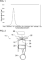
1 eine beispielhafte Zylinderdruckkurve eines Zylinders einer Brennkraftmaschine im Leerlauf; -
2 eine schematisch dargestellte beispielhafte Zylindereinheit gemäß der vorliegenden Offenbarung; -
3 eine perspektivische Ansicht eines Ventiltriebs der beispielhaften Zylindereinheit; -
4 eine Schnittdarstellung eines beispielhaften Zusatzventils in einer Schließstellung; -
5 eine Schnittdarstellung des beispielhaften Zusatzventils in einer Öffnungsstellung; -
6 eine Ventilsteuerkurve eines Einlassventils, eine Ventilsteuerkurve des bespielhaften Zusatzventils und eine beispielhafte Zylinderdruckkurve; -
7 eine schematische Darstellung einer beispielhaften Vorrichtung zur Drucklufterzeugung gemäß der vorliegenden Offenbarung; und -
8 eine Schnittdarstellung eines Rückschlagventils und des beispielhaften Zusatzventils.
-
1 an exemplary cylinder pressure curve of a cylinder of an internal combustion engine at idle; -
2 a schematically illustrated exemplary cylinder unit according to the present disclosure; -
3 a perspective view of a valve train of the exemplary cylinder unit; -
4 a sectional view of an exemplary additional valve in a closed position; -
5 a sectional view of the exemplary additional valve in an open position; -
6 a valve control curve of an intake valve, a valve control curve of the exemplary auxiliary valve and an exemplary cylinder pressure curve; -
7 a schematic representation of an exemplary apparatus for compressed air generation according to the present disclosure; and -
8th a sectional view of a check valve and the exemplary additional valve.
Die in den Figuren gezeigten Ausführungsformen stimmen zumindest teilweise überein, so dass ähnliche oder identische Teile mit den gleichen Bezugszeichen versehen sind und zu deren Erläuterung auch auf die Beschreibung der anderen Ausführungsformen bzw. Figuren verwiesen wird, um Wiederholungen zu vermeiden.The embodiments shown in the figures are at least partially identical, so that similar or identical parts are provided with the same reference numerals and to the explanation of which reference is also made to the description of the other embodiments or figures in order to avoid repetition.
Die
Vorzugsweise ist der jeweilige Zylinder bei der Druckluftentnahme im Leerlaufbetrieb und/oder nicht befeuert. Es ist allerdings auch möglich, dass der Zylinder befeuert ist. Beispielsweise kann die entnommene Druckluft in einem Druckluftspeicher gespeichert und/oder (direkt oder indirekt) zu pneumatischen Einrichtungen weitergeleitet werden. Beispielsweise kann bei einem Nutzfahrzeug Druckluft in einem Bereich zwischen 8 bar und 12 bar zum Betreiben einer Vielzahl von pneumatische Einrichtungen, zum Beispiel pneumatisch betätigte Bremsen, verwendet werden.Preferably, the respective cylinder in the compressed air removal in idle mode and / or not fired. However, it is also possible that the cylinder is fired. For example, the extracted compressed air can be stored in a compressed air storage and / or forwarded (directly or indirectly) to pneumatic devices. For example, in a commercial vehicle, compressed air in a range between 8 bar and 12 bar may be used to operate a variety of pneumatic devices, such as pneumatically actuated brakes.
Die
Die Zylindereinheit
Mittels eines Zusatzventils
Das Zusatzventil
Die
Der Ventiltrieb
Der Kipphebel
Der Ventiltrieb
Die Leerweg-Einrichtung
Das Zusatzventil
Der Ventiltrieb
Die
Das Zusatzventil
Die Arretierungsvorrichtung
In einer Schließstellung des Zusatzventils
Die Arretierungsvorrichtung
Es ist möglich, dass das Zusatzventil
Es ist möglich, dass ein Luftbedarf für Druckluft deutlich kleiner als ein Luftbedarf der Brennkraftmaschine zum Verbrennen von Kraftstoff ist. Dadurch kann beispielsweise das Zusatzventil
Die
In
In der
Die
Die Vorrichtung
Die Vorrichtung
Die
Das Rückschlagventil
Die Erfindung ist nicht auf die vorstehend beschriebenen bevorzugten Ausführungsbeispiele beschränkt. Vielmehr ist eine Vielzahl von Varianten und Abwandlungen möglich, die ebenfalls von dem Erfindungsgedanken Gebrauch machen und deshalb in den Schutzbereich fallen. Insbesondere beansprucht die Erfindung auch Schutz für den Gegenstand und die Merkmale der Unteransprüche unabhängig von den in Bezug genommenen Ansprüchen. Insbesondere sind die Merkmale des unabhängigen Anspruchs 1 unabhängig voneinander offenbart. Zusätzlich sind auch die Merkmale der Unteransprüche unabhängig von sämtlichen Merkmalen des unabhängigen Anspruchs 1 und beispielsweise unabhängig von den Merkmalen bezüglich des Vorhandenseins und/oder der Konfiguration der mehreren Gaswechselventile, des Zusatzventils und/oder des Ventiltriebs des unabhängigen Anspruchs 1 offenbart.The invention is not limited to the preferred embodiments described above. Rather, a variety of variants and modifications is possible, which also make use of the inventive idea and therefore fall within the scope. In particular, the invention also claims protection of the subject matter and the features of the subclaims independently of the claims referred to. In particular, the features of independent claim 1 are independently disclosed. In addition, the features of the subclaims are also disclosed independently of all the features of independent claim 1 and, for example, independently of the features relating to the presence and / or configuration of the plurality of gas exchange valves, the auxiliary valve and / or the valvetrain of independent claim 1.
BezugszeichenlisteLIST OF REFERENCE NUMBERS
- 1010
- Zylindereinheitcylinder unit
- 1212
- Einlassventil (Gaswechselventil)Inlet valve (gas exchange valve)
- 1414
- Auslassventil (Gaswechselventil)Exhaust valve (gas exchange valve)
- 1616
- Einlasskanalinlet channel
- 1818
- Verbrennungskammercombustion chamber
- 2020
- Auslasskanalexhaust port
- 2222
- Kolbenpiston
- 2424
- Kurbelwellecrankshaft
- 2626
- Zusatzventiladditional valve
- 2828
- Ventiltriebvalve train
- 3030
- Kipphebel (Kraftübertragungselement)Rocker arm (power transmission element)
- 3232
- Nockenwellecamshaft
- 3434
- Leerweg-EinrichtungLeerweg facility
- 3636
- Ventilfedervalve spring
- 3838
- Arretierungsvorrichtunglocking device
- 4040
- Sperrkörperblocking body
- 4242
- Umfangsnutcircumferential groove
- 4444
- Ventilschaftvalve stem
- 4646
- Ventiltellervalve disc
- 4848
- Vorrichtung zur DrucklufterzeugungDevice for compressed air generation
- 5050
- BrennkraftmaschineInternal combustion engine
- 5252
- DruckluftspeicherCompressed air storage
- 5454
- Rückschlagventilcheck valve
- 5656
- Sperrkörperblocking body
- 5858
- Druckluftkanal Compressed air duct
- AA
- DruckluftströmungCompressed air flow
- BB
- EinlassventilhubkurveEinlassventilhubkurve
- CC
- ZusatzventilhubkurveZusatzventilhubkurve
- DD
- ZylinderdruckverlaufCylinder pressure curve
ZITATE ENTHALTEN IN DER BESCHREIBUNG QUOTES INCLUDE IN THE DESCRIPTION
Diese Liste der vom Anmelder aufgeführten Dokumente wurde automatisiert erzeugt und ist ausschließlich zur besseren Information des Lesers aufgenommen. Die Liste ist nicht Bestandteil der deutschen Patent- bzw. Gebrauchsmusteranmeldung. Das DPMA übernimmt keinerlei Haftung für etwaige Fehler oder Auslassungen.This list of the documents listed by the applicant has been generated automatically and is included solely for the better information of the reader. The list is not part of the German patent or utility model application. The DPMA assumes no liability for any errors or omissions.
Zitierte PatentliteraturCited patent literature
- DE 19849914 C1 [0003]DE 19849914 C1 [0003]
Claims (15)
Priority Applications (2)
| Application Number | Priority Date | Filing Date | Title |
|---|---|---|---|
| DE102018108008.5A DE102018108008A1 (en) | 2018-04-05 | 2018-04-05 | Device for compressed air generation for an internal combustion engine with an additional valve |
| EP19166940.7A EP3550115B1 (en) | 2018-04-05 | 2019-04-03 | Device for the production of compressed air for a combustion engine with an auxiliary valve |
Applications Claiming Priority (1)
| Application Number | Priority Date | Filing Date | Title |
|---|---|---|---|
| DE102018108008.5A DE102018108008A1 (en) | 2018-04-05 | 2018-04-05 | Device for compressed air generation for an internal combustion engine with an additional valve |
Publications (1)
| Publication Number | Publication Date |
|---|---|
| DE102018108008A1 true DE102018108008A1 (en) | 2019-10-10 |
Family
ID=66092003
Family Applications (1)
| Application Number | Title | Priority Date | Filing Date |
|---|---|---|---|
| DE102018108008.5A Withdrawn DE102018108008A1 (en) | 2018-04-05 | 2018-04-05 | Device for compressed air generation for an internal combustion engine with an additional valve |
Country Status (2)
| Country | Link |
|---|---|
| EP (1) | EP3550115B1 (en) |
| DE (1) | DE102018108008A1 (en) |
Citations (7)
| Publication number | Priority date | Publication date | Assignee | Title |
|---|---|---|---|---|
| DE3041674A1 (en) * | 1980-11-05 | 1982-06-09 | Ernst Dipl.-Phys. 7730 Villingen-Schwenningen Jauch | IC engine suction air storage - involves feeding suction air during compression stroke into air reservoir for use on demand |
| DE19849914C1 (en) | 1998-10-29 | 1999-11-04 | Daimler Chrysler Ag | Internal combustion engine with auxiliary inlet valve |
| DE19902052A1 (en) * | 1999-01-20 | 2000-07-27 | Daimler Chrysler Ag | Internal combustion engine with compressor to produce compressed air, with oxidation catalytic converter in flow path between compressor and compressed air store |
| US7370630B2 (en) * | 2003-05-28 | 2008-05-13 | Lotus Cars Limited | Engine with a plurality of operating modes including operation by compressed air |
| DE102012206552A1 (en) * | 2012-04-20 | 2013-10-24 | Schaeffler Technologies AG & Co. KG | Internal combustion engine for motor vehicle, has multiple cam profiles, which are assigned to additional valve, where rotational movement of cam shaft is implemented by cam profiles during opening and closing of additional valve |
| DE102014116913A1 (en) * | 2013-12-18 | 2015-06-18 | Hyundai Motor Company | Loader engine |
| DE102015203382A1 (en) * | 2015-02-25 | 2016-08-25 | Bayerische Motoren Werke Aktiengesellschaft | Method for operating an internal combustion engine |
Family Cites Families (3)
| Publication number | Priority date | Publication date | Assignee | Title |
|---|---|---|---|---|
| JPS59102958U (en) * | 1982-12-27 | 1984-07-11 | 日野自動車株式会社 | Internal combustion engine auxiliary air control mechanism |
| JPS606026A (en) * | 1984-04-17 | 1985-01-12 | Takahiro Ueno | Method of operating internal-combustion engine |
| US20080087257A1 (en) * | 2006-04-24 | 2008-04-17 | Robinson Barnett J | Internal combustion engine with shared holding tank in cylinder head for elevated expansion ratio |
-
2018
- 2018-04-05 DE DE102018108008.5A patent/DE102018108008A1/en not_active Withdrawn
-
2019
- 2019-04-03 EP EP19166940.7A patent/EP3550115B1/en active Active
Patent Citations (7)
| Publication number | Priority date | Publication date | Assignee | Title |
|---|---|---|---|---|
| DE3041674A1 (en) * | 1980-11-05 | 1982-06-09 | Ernst Dipl.-Phys. 7730 Villingen-Schwenningen Jauch | IC engine suction air storage - involves feeding suction air during compression stroke into air reservoir for use on demand |
| DE19849914C1 (en) | 1998-10-29 | 1999-11-04 | Daimler Chrysler Ag | Internal combustion engine with auxiliary inlet valve |
| DE19902052A1 (en) * | 1999-01-20 | 2000-07-27 | Daimler Chrysler Ag | Internal combustion engine with compressor to produce compressed air, with oxidation catalytic converter in flow path between compressor and compressed air store |
| US7370630B2 (en) * | 2003-05-28 | 2008-05-13 | Lotus Cars Limited | Engine with a plurality of operating modes including operation by compressed air |
| DE102012206552A1 (en) * | 2012-04-20 | 2013-10-24 | Schaeffler Technologies AG & Co. KG | Internal combustion engine for motor vehicle, has multiple cam profiles, which are assigned to additional valve, where rotational movement of cam shaft is implemented by cam profiles during opening and closing of additional valve |
| DE102014116913A1 (en) * | 2013-12-18 | 2015-06-18 | Hyundai Motor Company | Loader engine |
| DE102015203382A1 (en) * | 2015-02-25 | 2016-08-25 | Bayerische Motoren Werke Aktiengesellschaft | Method for operating an internal combustion engine |
Also Published As
| Publication number | Publication date |
|---|---|
| EP3550115A1 (en) | 2019-10-09 |
| EP3550115B1 (en) | 2021-06-02 |
Similar Documents
| Publication | Publication Date | Title |
|---|---|---|
| DE102016003732A1 (en) | Variable valve actuator | |
| DE102017113783A1 (en) | Power transmission device | |
| EP0898059A2 (en) | Decompression valve engine brake | |
| WO2009021666A1 (en) | Valve train actuating device | |
| EP4004350B1 (en) | Variable valve drive for braking mode | |
| DE102015207622A1 (en) | Electrohydraulic valve train for an internal combustion engine | |
| DE102015016526A1 (en) | Method for operating a reciprocating internal combustion engine | |
| DE102018105359A1 (en) | Variable valve train with sliding cam system for an internal combustion engine | |
| DE19614923C2 (en) | Motor vehicle with an additional braking device and method for emergency braking of such a motor vehicle | |
| EP3550115B1 (en) | Device for the production of compressed air for a combustion engine with an auxiliary valve | |
| DE102017120150A1 (en) | Method for braking an internal combustion engine | |
| DE102015205297A1 (en) | Internal combustion engine | |
| EP2789853A1 (en) | Device for conveying compressed air for devices in motor vehicles operated by compressed air | |
| DE102011014239A1 (en) | Internal combustion engine apparatus for use with valve train apparatus for motor vehicle, has valve lift switching unit and cam tracks, where exhaust gas recirculation of throttle device is adjusted by a control- and regulating unit | |
| DE102016013370A1 (en) | Internal combustion engine device for carrying out a direct start | |
| DE10250771B4 (en) | Motor brake device and method for its control | |
| EP3519684B1 (en) | Reciprocating-piston internal combustion engine with device for increasing the torque thereof | |
| DE102016213976A1 (en) | Electrohydraulic valve train of an internal combustion engine | |
| AT521169B1 (en) | Device for an internal combustion engine with an additional valve unit | |
| DE102010054520A1 (en) | Four stroke-reciprocating piston-internal combustion engine has one and another cylinder and one and another piston, which are driven in lifting motion by crank mechanism | |
| DE102018105357A1 (en) | Method for operating an internal combustion engine to increase an exhaust gas temperature | |
| DE102016015457A1 (en) | Method for operating a reciprocating internal combustion engine | |
| DE102021118768A1 (en) | Valve arrangement of an internal combustion engine and an internal combustion engine | |
| DE102021002758A1 (en) | Internal combustion engine for a motor vehicle | |
| DE102019114046A1 (en) | Valve drive for an internal combustion engine of a motor vehicle, internal combustion engine, motor vehicle and use of a valve drive |
Legal Events
| Date | Code | Title | Description |
|---|---|---|---|
| R079 | Amendment of ipc main class |
Free format text: PREVIOUS MAIN CLASS: F01L0001020000 Ipc: F02B0021000000 |
|
| R163 | Identified publications notified | ||
| R081 | Change of applicant/patentee |
Owner name: MAN TRUCK & BUS SE, DE Free format text: FORMER OWNER: MAN TRUCK & BUS AG, 80995 MUENCHEN, DE |
|
| R082 | Change of representative |
Representative=s name: V. BEZOLD & PARTNER PATENTANWAELTE - PARTG MBB, DE |
|
| R119 | Application deemed withdrawn, or ip right lapsed, due to non-payment of renewal fee |