HINTERGRUND DER ERFINDUNG BACKGROUND OF THE INVENTION
1. Gebiet der Erfindung 1. Field of the invention
Die vorliegende Erfindung betrifft Schleifmaschinen. The present invention relates to grinding machines.
2. Beschreibung des Stands der Technik 2. Description of the Related Art
Die japanische geprüfte Gebrauchsmusteranmeldung mit der Offenlegungsnummer S60-26901 ( JP S60-26901 Y2 ) offenbart einen Spindelstock, der mit einem drückenden Element bereitgestellt ist, das durch ein Übertragungsgerät ein an einer Position zum Bearbeiten mit einer Schleifscheibe angeordnetes Werkstück zu einer Position zum Entladen und Laden drückt. Die JP S60-26901 Y2 beschreibt eine Technik, in der ein beschränkendes Element an der Lade- und Entladeposition platziert ist, und das drückende Element ein an der Bearbeitungsposition befindliches Werkstück zu der Position bewegt, wo das Werkstück das beschränkende Element berührt. Japanese Examined Utility Model Application Laid-Open No. S60-26901 ( JP S60-26901 Y2 ) discloses a headstock provided with a pressing member that presses a workpiece disposed at a position for machining with a grinding wheel to a position for discharging and loading by a transmission apparatus. JP S60-26901 Y2 describes a technique in which a restricting member is placed at the loading and unloading position, and the pressing member moves a workpiece at the machining position to the position where the workpiece contacts the restricting member.
Aus dem Stand der Technik ist eine Technologie bekannt, in der ein Sensor anstelle des beschränkenden Elements verwendet wird, das in der JP S-60-26901 Y2 verwendet wird, wenn das drückende Element ein Werkstück zu einer vorbestimmten Position bewegt. Der Sensor erfasst, wenn ein Werkstück zu der vorbestimmten Position bewegt wurde. Das drückende Gerät bewegt das Werkstück, bis der Sensor das Werkstück erfasst. Jedoch kann in dem Fall, in dem der Sensor in einem freigelegten Zustand ist, an der Position zum Bearbeiten mit der Schleifscheibe und dem Kühlmittel im Einsatz während des Schleifens mit der Schleifscheibe das Kühlmittel auf den Sensor spritzen, was die Erfassungsgenauigkeit des Sensors reduzieren kann. From the prior art, a technology is known in which a sensor is used in place of the restricting element used in the JP S-60-26901 Y2 is used when the pressing member moves a workpiece to a predetermined position. The sensor detects when a workpiece has been moved to the predetermined position. The pushing device moves the workpiece until the sensor detects the workpiece. However, in the case where the sensor is in an uncovered state, at the position for machining with the grinding wheel and the coolant in use during grinding with the grinding wheel, the coolant may splash on the sensor, which may reduce the detection accuracy of the sensor.
ZUSAMMENFASSUNG DER ERFINDUNG SUMMARY OF THE INVENTION
Es ist eine Aufgabe der vorliegenden Erfindung, eine Schleifmaschine bereitzustellen, die einen Sensor zum Erfassen der Position eines Werkstücks hat, und die eine Reduktion in der Erfassungsgenauigkeit des Sensors verhindern kann. It is an object of the present invention to provide a grinding machine having a sensor for detecting the position of a workpiece, and which can prevent a reduction in the detection accuracy of the sensor.
Eine Schleifmaschine gemäß einem Gesichtspunkt der vorliegenden Erfindung hat: eine Spindel, die ein Werkstück in einem Bearbeitungsbereich lagert; einen Spindelstockkörper, der die Spindel drehbar lagert; eine Schleifscheibe, die das durch die Spindel gelagerte Werkstück schleift; einen Kühlmittelzufuhrabschnitt, der ein Kühlmittel zu dem Bearbeitungsbereich zuführt; eine Schalteinheit, die durch den Spindelstockkörper so gelagert ist, dass eine Größe, um die die Schalteinheit von einer zu dem Bearbeitungsbereich gerichteten Endfläche des Reitstockkörpers vorragt, variabel ist, und die das in dem Bearbeitungsbereich platzierte Werkstück von einer Position, wo das Werkstück durch die Spindel gelagert ist, zu einer Position bewegt, wo das Werkstück von der Spindel getrennt wird; und eine Sensoreinheit, die die Größe erfasst, um die die Schalteinheit von der zu dem Bearbeitungsbereich gerichteten Endfläche des Spindelstockkörpers vorragt. A grinding machine according to one aspect of the present invention has: a spindle supporting a workpiece in a machining area; a headstock body rotatably supporting the spindle; a grinding wheel which grinds the workpiece supported by the spindle; a coolant supply section that supplies a coolant to the processing area; a shift unit supported by the headstock body so that a size by which the shift unit protrudes from an end face of the tailstock body directed to the machining area is variable, and the workpiece placed in the machining area is moved from a position where the workpiece passes through Spindle is mounted, moved to a position where the workpiece is separated from the spindle; and a sensor unit that detects the amount by which the indexing unit protrudes from the end face of the headstock body facing the machining area.
Die Sensoreinheit ist in einem Bereich platziert, der über der gegenüberliegenden Endfläche des Spindelstockkörpers von der Endfläche angeordnet ist, die zu dem Bearbeitungsbereich gerichtet ist, und erfasst einen Teil der Schalteinheit, der nicht von der Endfläche des Spindelstockkörpers vorragt, die zu dem Bearbeitungsbereich gerichtet ist. The sensor unit is placed in an area disposed above the opposite end surface of the headstock from the end surface facing the machining area, and detects a part of the indexing unit that does not protrude from the end surface of the headstock body facing the machining area ,
Gemäß der Schleifmaschine des voranstehend beschriebenen Gesichtspunkts wird ein Kühlmittel während des Schleifens des Werkstücks zu dem Bearbeitungsbereich zugeführt. Die Sensoreinheit ist in dem Bereich platziert, der über der gegenüberliegenden Endfläche des Reitstockkörpers von der zu dem Bearbeitungsbereich gerichteten Endfläche angeordnet ist, und erfasst einen Teil der Schalteinheit, der nicht von der zu dem Bearbeitungsbereich R gerichteten Endfläche des Spindelstockkörpers vorragt. Es kann daher verhindert werden, dass Kühlmittel auf die Sensoreinheit spritzt, wodurch eine Reduktion in der Erfassungsgenauigkeit der Sensoreinheit aufgrund des auf die Sensoreinheit spritzenden Kühlmittels verhindert werden kann. According to the grinding machine of the above-described aspect, a coolant is supplied to the processing area during grinding of the workpiece. The sensor unit is placed in the area located above the opposite end surface of the tailstock body from the end surface facing the machining area, and detects a part of the indexing unit that does not protrude from the end surface of the headstock body facing the machining area R. Therefore, coolant can be prevented from being splashed on the sensor unit, whereby a reduction in the detection accuracy of the sensor unit due to the coolant spouting on the sensor unit can be prevented.
KURZE BESCHREIBUNG DER ZEICHNUNGEN BRIEF DESCRIPTION OF THE DRAWINGS
Die voranstehend beschriebenen und weitere Merkmale und Vorteile der Erfindung werden aus der folgenden Beschreibung von beispielhaften Ausführungsformen mit Bezug auf die anhängenden Zeichnungen deutlich werden, worin gleiche Bezugszeichen verwendet werden, um gleiche Elemente zu bezeichnen, und worin: The above-described and other features and advantages of the invention will become apparent from the following description of exemplary embodiments with reference to the accompanying drawings, in which like reference numerals are used to designate like elements, and wherein:
1 eine Ansicht ist, die die Konfiguration einer Schleifmaschine gemäß einer Ausführungsform der vorliegenden Erfindung zeigt; 1 is a view showing the configuration of a grinding machine according to an embodiment of the present invention;
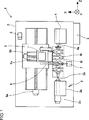
2 eine Vorderansicht eines Spindelstockes; und 2 a front view of a headstock; and
3 eine Schnittansicht des Spindelstocks entlang einer Linie III-III in 2 ist. 3 a sectional view of the headstock along a line III-III in 2 is.
AUSFÜHRLICHE BESCHREIBUNG VON AUSFÜHRUNGSFORMEN DETAILED DESCRIPTION OF EMBODIMENTS
Eine Schleifmaschine 1 gemäß einer Ausführungsform der vorliegenden Erfindung wird im Folgenden mit Bezug auf die anhängenden Zeichnungen beschrieben. Die Schleifmaschine 1 ist eine Scheibenspindelstockquerschleifmaschine, die verursacht, dass ein Scheibenspindelstock 5 ein Bett 2 quert (den Scheibenspindelstock 5 relativ zu dem Bett 2 in der Z-Achsenrichtung bewegt). Ein durch die Schleifmaschine 1 zu schleifendes Werkstück W ist eine Kurbelwelle. A grinding machine 1 according to one embodiment of the present invention will be described below with reference to the accompanying drawings. The grinding machine 1 is a Disc spindle stick grinder that creates a disc spindle stick 5 a bed 2 crosses (the disk spindle stick 5 relative to the bed 2 moved in the Z-axis direction). A through the grinder 1 To be sanded workpiece W is a crankshaft.
In der Schleifmaschine 1 sind ein Spindelstock 3 und ein Reitstock 4 auf der oberen Oberfläche des auf einer Installationsoberfläche befestigten Betts 2 platziert. Eine Spindel 3a ist durch den Spindelstock 3 so gelagert, dass die Spindel 3a sich relativ zu einem Spindelstockkörper 3b drehen kann. Eine Spitze 4a ist drehbar durch den Reitstock 4 gelagert. In dem Spindelstock 3 ist die Spindel 3a drehend durch einen Motor 3c angetrieben. Das Werkstück W ist an seinen beiden Enden durch die Spindel 3a und die Spitze 4a gelagert. In the grinding machine 1 are a headstock 3 and a tailstock 4 on the upper surface of the bed attached to an installation surface 2 placed. A spindle 3a is through the headstock 3 so stored that the spindle 3a relative to a headstock body 3b can turn. A peak 4a is rotatable by the tailstock 4 stored. In the headstock 3 is the spindle 3a turning by a motor 3c driven. The workpiece W is at its two ends by the spindle 3a and the top 4a stored.
Der Scheibenspindelstock 5 ist ebenfalls an der oberen Oberfläche des Betts 2 vorgesehen. Der Scheibenspindelstock 5 kann sich in der Z-Achsenrichtung (der axialen Richtung des Werkstücks W) und der X-Achsenrichtung (der Richtung rechtwinklig zu der Achse des Werkstücks W) bewegen. Der Scheibenspindelstock 5 wird durch einen Motor 5a angetrieben, um sich in der Z-Achsenrichtung zu bewegen, und wird durch einen Motor 5b angetrieben, um sich in der X-Achsenrichtung zu bewegen. Eine Schleifscheibe 6, die das Werkstück W schleift, ist drehbar in dem Scheibenspindelstock 5 platziert. Die Schleifscheibe 6 ist drehend durch einen Motor 6a angetrieben. The disc spindle stick 5 is also on the top surface of the bed 2 intended. The disc spindle stick 5 may move in the Z-axis direction (the axial direction of the workpiece W) and the X-axis direction (the direction perpendicular to the axis of the workpiece W). The disc spindle stick 5 is by a motor 5a driven to move in the Z-axis direction, and is driven by a motor 5b driven to move in the X-axis direction. A grinding wheel 6 that grinds the workpiece W is rotatable in the disk spindle 5 placed. The grinding wheel 6 is turning by a motor 6a driven.
Ein Größenbestimmungsgerät 7 und ein Kühlmittelzufuhrabschnitt 8 sind ebenfalls auf der oberen Oberfläche des Betts 2 platziert. Das Größenbestimmungsgerät 7 misst den Außendurchmesser eines Teils des Werkstücks W, das geschliffen wird, und der Kühlmittelzufuhrabschnitt 8 führt Kühlmittel zu dem Teil zu, das geschliffen wird. Der Kühlmittelzufuhrabschnitt 8 führt das Kühlmittel zu einer Düse (nicht gezeigt) zu, die in dem Spindelstock 3 vorgesehen ist, und das Kühlmittel wird von der Düse zu dem Teil zugeführt, das geschliffen wird. Die Schleifmaschine 1 ist außerdem mit einem Steuergerät 9 bereitgestellt. Das Steuergerät 9 steuert antreibend die Motoren 3c, 5a, 5b, 6a. A sizer 7 and a coolant supply section 8th are also on the top surface of the bed 2 placed. The sizing device 7 measures the outer diameter of a part of the workpiece W being ground and the coolant supply section 8th adds coolant to the part being ground. The coolant supply section 8th directs the coolant to a nozzle (not shown) in the headstock 3 is provided, and the coolant is supplied from the nozzle to the part to be ground. The grinding machine 1 is also with a control unit 9 provided. The control unit 9 drivingly controls the motors 3c . 5a . 5b . 6a ,
Die Konfiguration des Spindelstocks 3 wird im Folgenden im Detail beschrieben. Wie aus 1 ersichtlich ist, hat der Spindelstock 3 die Spindel 3a, den Spindelstockkörper 3b und den Motor 3c. Wie voranstehend beschrieben wurde, lagert die Spindel 3a ein Ende des Werkstücks W. Die Spindel 3a ist drehbar durch den Spindelstockkörper 3b derart gelagert, dass das Spitzenende der Spindel 3a, die das Werkstück W lagert, zu dem Bearbeitungsbereich R gerichtet ist. Der Bearbeitungsbereich R ist ein Bereich, wo das Werkstück W durch die Schleifscheibe 6 geschliffen wird. Der Spindelstockkörper 3b ist so konfiguriert, dass die Richtung des Spitzenendes der Spindel 3a auf dem Bett 2 angepasst werden kann. The configuration of the headstock 3 will be described in detail below. How out 1 is apparent, the headstock has 3 the spindle 3a , the headstock body 3b and the engine 3c , As described above, the spindle supports 3a one end of the workpiece W. The spindle 3a is rotatable by the headstock body 3b stored such that the tip end of the spindle 3a , which supports the workpiece W, is directed to the processing area R. The machining area R is an area where the workpiece W passes through the grinding wheel 6 is sanded. The headstock body 3b is configured so that the direction of the tip end of the spindle 3a on the bed 2 can be adjusted.
Wie aus 2 ersichtlich ist, ist die Spindel 3a auf der Endfläche des Spindelstockkörpers 3b platziert, die zu dem Bearbeitungsbereich R gerichtet ist, und der Motor 3c ist extern an der gegenüberliegenden Endfläche des Spindelstockkörpers 3b von dem Bearbeitungsbereich R angebracht. Der Motor 3c ist ein Motor, der eine Antriebskraft zum Drehen der Spindel 3a aufbringt. Der Motor 3c ist in dem Bereich platziert, der an der gegenüberliegenden Seite des Spindelstockkörpers 3b von dem Bearbeitungsbereich R platziert ist. Der Spindelstockkörper 3b ist außerdem mit einem Schaltgerät 10 bereitgestellt. Das Schaltgerät 10 ist unter der Spindel 3a und dem Motor 3c platziert und wird verwendet, um das Werkstück W zu bewegen (siehe 1). Das Schaltgerät 10 hat eine Schalteinheit 20, eine Basis 30 zum vorläufigen Halten, und eine Sensoreinheit 40. How out 2 it can be seen, is the spindle 3a on the end face of the headstock body 3b placed, which is directed to the processing area R, and the engine 3c is external to the opposite end surface of the headstock body 3b attached from the processing area R. The motor 3c is a motor that provides a driving force to rotate the spindle 3a applies. The motor 3c is placed in the area that is on the opposite side of the headstock body 3b from the processing area R is placed. The headstock body 3b is also equipped with a switching device 10 provided. The switching device 10 is under the spindle 3a and the engine 3c is placed and used to move the workpiece W (see 1 ). The switching device 10 has a switching unit 20 , One Base 30 for temporary holding, and a sensor unit 40 ,
Wie aus 3 ersichtlich ist, ist die Schalteinheit 20 ein Hydraulikzylinder mit einem Zylinderkörper 21, einem Kolben 22 und einer Stange 23 und durch das Steuergerät 9 gesteuert (siehe 1). Ein Teil der Stange 23 ragt von der gegenüberliegenden Endfläche (der linken Endfläche in 3) des Spindelstockkörpers 3b von dem Bearbeitungsbereich R vor, und das vorragende Teil der Stange 23 ist in einem Stangeaufnahmeabschnitt 24 aufgenommen. How out 3 it can be seen, is the switching unit 20 a hydraulic cylinder with a cylinder body 21 , a piston 22 and a pole 23 and through the controller 9 controlled (see 1 ). Part of the rod 23 protrudes from the opposite end face (the left end face in 3 ) of the headstock body 3b from the processing area R, and the projecting part of the bar 23 is in a pole receiving section 24 added.
Der Kolben 22 ist sowohl in dem Zylinderkörper 21 wie auch dem Stangenaufnahmeabschnitt 24 aufgenommen und mit der Stange 23 in dem Stangenaufnahmeabschnitt 24 gekoppelt. Ein erstreckter Abschnitt 25, der sich in die gegenüberliegende Richtung (links in 3) zu der Richtung erstreckt, in der die Stange 23 sich erstreckt, ist mit dem Kolben 22 gekoppelt, und ein erfasster Abschnitt 26, der sich nach unten erstreckt, ist an dem Spitzenende des erstreckten Abschnitts 25 ausgebildet. In 3 ist die Position des erstreckten Abschnitts 25 durch gestrichelte Linien gezeigt. Der erstreckte Abschnitt 25 kann an die Stange 23 gekoppelt werden. The piston 22 is both in the cylinder body 21 as well as the pole receiving section 24 picked up and with the rod 23 in the pole receiving section 24 coupled. An extended section 25 moving in the opposite direction (left in 3 ) extends to the direction in which the rod 23 extends, is with the piston 22 coupled, and a detected section 26 which extends downwardly is at the tip end of the extended portion 25 educated. In 3 is the position of the extended section 25 shown by dashed lines. The stretched section 25 can go to the bar 23 be coupled.
Der Kolben 22 bewegt sich gemäß einem Öldruck, der zu dem Zylinderkörper 21 zugeführt wird, hin und her. Die Stange 23 und der erfasste Abschnitt 26 erstrecken sich und ziehen sich zurück gemäß der Hin- und Herbewegung des Kolbens 22. Ein Sensoranbringungsabschnitt 27 ist an dem Stangenaufnahmeabschnitt 24 so angebracht, dass er sich von dem Stangenaufnahmeabschnitt 24 in die entgegengesetzte Richtung (die linke Richtung in 2) zu der Richtung erstreckt, in der die Stange 23 sich erstreckt. The piston 22 moves in accordance with an oil pressure to the cylinder body 21 is fed, back and forth. The pole 23 and the captured section 26 extend and retract according to the reciprocating motion of the piston 22 , A sensor attachment section 27 is on the pole receiving section 24 mounted so as to extend from the bar receiving section 24 in the opposite direction (the left direction in 2 ) extends to the direction in which the rod 23 extends.
Die Basis 30 zum vorläufigen Halten ist ein Abschnitt, der das Werkstück W von unten lagert, und ist ebenfalls in dem Bearbeitungsbereich R angeordnet. Die Basis 30 zum vorläufigen Halten ist mit dem Spitzenende der Stange 23 gekoppelt, und das durch die Basis 30 zum vorläufigen Halten gelagerte Werkstück W bewegt sich mit der Basis 30 zum vorläufigen Halten, wenn die Stange 23 sich erstreckt und zusammenzieht. The base 30 for provisional holding is a portion which supports the workpiece W from below, and is also located in the processing area R. The base 30 for temporary holding is with the top end of the pole 23 coupled, and that through the base 30 workpiece W supported for temporary holding moves with the base 30 for temporary holding when the rod 23 extends and contracts.
Die Sensoreinheit 40 ist ein Sensor, der die Größe erfasst, mit der die Stange 23 von der Oberfläche des Spindelstockkörpers 3b vorragt, die zu dem Bearbeitungsbereich R gerichtet ist. Die Sensoreinheit 40 hat ein Paar von Annäherungssensoren 41, 42. Das Paar Annäherungssensoren 41, 42 ist an dem Sensoranbringungsabschnitt 27 an Positionen angebracht, die zu einem Bereich gerichtet sind, in dem der erfasste Abschnitt 26 sich bewegt, wenn die Stange 23 sich erstreckt und zurückzieht. Die Sensoreinheit 40 ist nämlich in dem Bereich platziert, der an der gegenüberliegenden Seite des Spindelstockkörpers 3b von dem Bearbeitungsbereich R angeordnet ist. Das Paar Annäherungssensoren 41, 42 sind nebeneinander in der Richtung angeordnet, in der die Stange 23 sich erstreckt und zurückzieht, und eine Annäherungssensor 41 ist näher an dem Bearbeitungsbereich R als der andere Annäherungssensor 42 angeordnet. Ein optischer Sensor, oder ein Sensor, der Ultraschallwellen usw. erfasst, kann anstelle der Annäherungssensoren 41, 42 verwendet werden. The sensor unit 40 is a sensor that measures the size of the rod 23 from the surface of the headstock body 3b protruding toward the processing area R. The sensor unit 40 has a pair of proximity sensors 41 . 42 , The pair of proximity sensors 41 . 42 is at the sensor attachment portion 27 attached to positions that are directed to an area in which the detected portion 26 moves when the pole 23 extends and retreats. The sensor unit 40 Namely, it is placed in the area that is on the opposite side of the headstock body 3b is arranged from the processing area R. The pair of proximity sensors 41 . 42 are arranged side by side in the direction in which the rod 23 extends and retreats, and a proximity sensor 41 is closer to the processing area R than the other approach sensor 42 arranged. An optical sensor, or a sensor that detects ultrasonic waves, etc., may be used instead of the proximity sensors 41 . 42 be used.
Wenn der erfasste Abschnitt 26, der sich mit der Stange 23 der Schalteinheit 20 bewegt, vor einen Annäherungssensor 41 gerät, während die Stange 23 ausgestreckt wird, erfasst der eine Annäherungssensor 41 den erfassten Abschnitt 26 und sendet ein Erfassungssignal zu dem Steuergerät 9. In Erwiderung auf das Erfassungssignal von dem einen Annäherungssensor 41 hält das Steuergerät 9 das Antreiben der Schalteinheit 20 an. Wenn der erfasst Abschnitt 26 vor den anderen Annäherungssensor 42 gerät, während die Stange 23 zurückgezogen wird, erfasst der andere Annäherungssensor 42 ähnlich den erfassten Abschnitt 26 und sendet ein Erfassungssignal zu dem Steuergerät 9. In Erwiderung auf das Erfassungssignal von dem anderen Annäherungssensor 42 hält das Steuergerät 9 das Antreiben der Schalteinheit 20 an. If the captured section 26 who is with the rod 23 the switching unit 20 moved, in front of a proximity sensor 41 device while the rod 23 is stretched, which detects a proximity sensor 41 the captured section 26 and sends a detection signal to the controller 9 , In response to the detection signal from the one proximity sensor 41 stops the controller 9 driving the switching unit 20 at. When the captured section 26 in front of the other proximity sensor 42 device while the rod 23 is retracted, the other proximity sensor detects 42 similar to the captured section 26 and sends a detection signal to the controller 9 , In response to the detection signal from the other proximity sensor 42 stops the controller 9 driving the switching unit 20 at.
Das Paar Annäherungssensoren 41, 42 ist durch Bohrungen 27a, 27b eingefügt, die in dem Sensoranbringungsabschnitt 27 ausgebildet sind, und ist darin befestigt. Die Bohrung 27a, durch die der eine Annäherungssensor 41 eingefügt wird, ist ein Langloch, das in der Richtung, in der sich die Stange 23 erstreckt (die seitliche Richtung in 3) länger ist. Ist gestattet, dass die Anbringungsposition des einen Annährungssensors 41 an dem Sensoranbringungsabschnitt 27 in Richtung angepasst werden kann, in der sich die Stange 23 erstreckt und zurückzieht. The pair of proximity sensors 41 . 42 is through holes 27a . 27b inserted in the sensor attachment portion 27 are formed, and is fixed therein. The hole 27a through which the one proximity sensor 41 is inserted, is a slot in the direction in which the rod 23 extends (the lateral direction in 3 ) is longer. Is allowed that the mounting position of an approximate sensor 41 at the sensor attachment portion 27 Can be adjusted in the direction of the pole 23 extends and withdraws.
Wie voranstehend beschrieben wurde, ist die Sensoreinheit 40 in dem Bereich platziert, der an der gegenüberliegenden Seite des Spindelstockkörpers 3b von dem Maschinenbereich R angeordnet ist, das Paar der Annäherungssensoren 41, 42 erfasst den erfassten Abschnitt 26, nämlich einen Teil der Schalteinheit 20, der von dem Spindelstockkörper 3b in dem Bereich freigelegt ist, der auf der gegenüberliegenden Seite des Spindelstockkörpers 3b von dem Bearbeitungsbereich R liegt. In diesem Fall kann verhindert werden, dass ein in dem Bearbeitungsbereich R abgegebenes Kühlmittel während des Schleifens des Werkstücks W auf die Sensoreinheit 40 spritzt. Eine Reduktion der Erfassungsgenauigkeit der Sensoreinheit 40 kann deswegen verhindert werden. Da der Zylinderkörper 21 und der Kolben 22 der Schalteinheit 20 unter dem Motor 3c vorgesehen sind, kann eine Fehlfunktion der Schalteinheit 20 aufgrund von Kühlmittel verhindert werden. As described above, the sensor unit is 40 placed in the area that is on the opposite side of the headstock body 3b from the machine area R, the pair of proximity sensors 41 . 42 captures the captured section 26 namely a part of the switching unit 20 that of the headstock body 3b in the area exposed on the opposite side of the headstock body 3b from the processing area R lies. In this case, a coolant discharged in the processing area R can be prevented from being dragged onto the sensor unit during grinding of the workpiece W. 40 injected. A reduction of the detection accuracy of the sensor unit 40 can therefore be prevented. As the cylinder body 21 and the piston 22 the switching unit 20 under the engine 3c are provided, a malfunction of the switching unit 20 be prevented due to coolant.
Da ein Teil der Schalteinheit 20 und der Sensoreinheit 40 in einem Raum unter dem Motor 3c platziert sind, kann ein Anstieg der Gesamtgröße des Spindelstocks 3 verhindert werden. Die Sensoreinheit 40 ist derart in dem Bereich platziert, der auf der gegenüberliegenden Seite des Spindelstockkörpers 3b von dem Bearbeitungsbereich R angeordnet ist, dass das Paar der Annäherungssensoren 41, 42 von dem Spindelstockkörper 3b freigelegt sind. Dies erleichtert ein wirkungsvolles Ersetzen in einem Fall eines Versagens usw. des Paars der Annäherungssensoren 41, 42. Zusätzlich ist der eine Annäherungssensor 41 an dem Sensoranbringungsabschnitt 27 so angebracht, dass die Position des einen Annäherungssensors 41 in der Richtung angepasst werden kann, in der die Stange 23 sich erstreckt und zurückzieht. Dies erleichtert die Anpassung der Position des einen Annäherungssensors 41. As part of the switching unit 20 and the sensor unit 40 in a room under the engine 3c may be an increase in the overall size of the headstock 3 be prevented. The sensor unit 40 is placed in the area that is on the opposite side of the headstock body 3b is arranged from the processing area R that the pair of proximity sensors 41 . 42 from the headstock body 3b are exposed. This facilitates effective replacement in case of failure, etc. of the pair of proximity sensors 41 . 42 , In addition, the is a proximity sensor 41 at the sensor attachment portion 27 so attached, that the position of the one proximity sensor 41 can be adjusted in the direction in which the rod 23 extends and retreats. This facilitates the adjustment of the position of the one proximity sensor 41 ,
Der Betrieb der Schleifmaschine 1 wird im Folgenden beschrieben. Wie aus 1 bis 3 ersichtlich ist, wenn ein Werkstück W anzubringen oder abzunehmen ist, ist der Reitstock 4 weiter von dem Spindelstock 3 entfernt, als wenn das Schleifen durchgeführt wird. Darüber hinaus ist die Stange 23 erstreckt, und die Basis 30 zum vorläufigen Halten wird in eine Position entfernt von dem Spindelstockkörper 3b bewegt. The operation of the grinding machine 1 is described below. How out 1 to 3 it can be seen when a workpiece W is to be attached or removed, the tailstock is 4 further from the headstock 3 removed as if the grinding is being performed. In addition, the pole 23 extends, and the base 30 for provisional holding is moved to a position away from the headstock body 3b emotional.
Nachdem das Werkstück W auf der Basis 30 zum vorläufigen Halten platziert wurde, wird die Stange 23 zurückgezogen, um die Basis 30 zum vorläufigen Halten zu dem Spindelstockkörper 3b zu bewegen, so dass das Ende des Werkstücks W die Spindel 3a berührt. Das Steuergerät 9 steuert antreibend die Schalteinheit 20, um die Stange 23 zurückzuziehen. Das Steuergerät 9 hält das Antreiben der Schalteinheit 20 an, wenn sie von dem anderen Annäherungssensor 42 ein Erfassungssignal empfängt. In 2 und 3 sind die Positionen der Basis 30 zum vorläufigen Halten, der erstreckte Abschnitt 25 und der erfasste Abschnitt 26, wenn die Stange 23 sich in einem zurückgezogenen Zustand befindet, durch Strich-Punkt-Linien dargestellt. After the workpiece W on the base 30 is placed for temporary holding, the rod becomes 23 withdrew to the base 30 for temporary holding to the headstock body 3b to move so that the end of the workpiece W the spindle 3a touched. The control unit 9 drivingly controls the switching unit 20 to the pole 23 withdraw. The control unit 9 stops driving the switching unit 20 when viewed from the other proximity sensor 42 receives a detection signal. In 2 and 3 are the positions of the base 30 to the provisional holding, the stretched section 25 and the captured section 26 if the rod 23 is in a retracted state, represented by dash-dot lines.
Darauf folgend wird der Reitstock 4 zurück zu dem Spindelstock 3 bewegt, so dass das Werkstück W, das durch die Basis 30 zum vorläufigen Halten gelagert ist, drehbar an seinen beiden Enden durch die Spindel 3a und die Spitze 4a gelagert ist. Die äußere Randoberfläche des Werkstücks W ist dann durch ein auf dem Spindelstockkörper 3b bereitgestelltes Futter (nicht gezeigt) gehalten, und das Werkstück W wird durch die Schleifscheibe 6 geschliffen. Subsequently, the tailstock 4 back to the headstock 3 moves so that the workpiece W, passing through the base 30 is supported for temporary holding, rotatably at its two ends by the spindle 3a and the top 4a is stored. The outer edge surface of the workpiece W is then by a on the headstock body 3b provided chuck (not shown), and the workpiece W is passed through the grinding wheel 6 ground.
Wie voranstehend beschrieben wurde, ist die Sensoreinheit 40 in dem Bereich platziert, der an der gegenüberliegenden Seite des Spindelstockkörpers 3b von dem Bearbeitungsbereich R angeordnet ist, und erfasst den erfassten Abschnitt 26, nämlich einen Teil der Schalteinheit 20, der in dem Bereich, der an der gegenüberliegenden Seite des Spindelstocks 3b von dem Bearbeitungsbereich R angeordnet ist, freigelegt ist. Somit kann verhindert werden, dass ein in den Bearbeitungsbereich R abgegebenes Kühlmittel während des Schleifens des Werkstücks W auf die Sensoreinheit 40 spritzt. Eine Reduktion der Erfassungsgenauigkeit der Sensoreinheit 40 kann daher verhindert werden. Da der Zylinderkörper 21 und der Kolben 22 unter dem Motor 3c vorgesehen sind, kann eine Fehlfunktion der Schalteinheit 20 aufgrund des auf den Zylinderkörper 21 und den Kolben 22 spritzenden Kühlmittels verhindert werden. As described above, the sensor unit is 40 placed in the area that is on the opposite side of the headstock body 3b from the processing area R, and detects the detected portion 26 namely a part of the switching unit 20 which is in the area on the opposite side of the headstock 3b from the processing area R is exposed. Thus, a coolant discharged into the processing region R can be prevented from being dragged onto the sensor unit during grinding of the workpiece W. 40 injected. A reduction of the detection accuracy of the sensor unit 40 can therefore be prevented. As the cylinder body 21 and the piston 22 under the engine 3c are provided, a malfunction of the switching unit 20 due to the on the cylinder body 21 and the piston 22 spraying coolant can be prevented.
Nachdem das Schleifen beendet ist, wird der Reitstock 4 von dem Spindelstock 3 mitbewegt. Da die Basis 30 zum vorläufigen Halten unter dem Werkstück W angeordnet ist, kann verhindert werden, dass das Werkstück fällt, wenn der Reitstock 4 bewegt wird. Danach wird die Stange 23 ausgestreckt, um das Werkstück W von dem Spindelstock 3 wegzubewegen, und das Werkstück W wird ausgetauscht. Das Steuergerät 9 steuert antreibend die Schalteinheit 20, die Stange 23 zu erstrecken. Das Steuergerät 9 hält das Antreiben der Schalteinheit 20 an, wenn sie ein Erfassungssignal von dem einen Annäherungssensor 41 empfängt. Ein Portallader usw. wird verwendet, um das Werkstück W in die Schleifmaschine 1 zu laden. After the grinding is completed, the tailstock 4 from the headstock 3 moved. Because the base 30 for temporary holding under the workpiece W, the workpiece can be prevented from falling when the tailstock 4 is moved. After that, the rod becomes 23 extended to the workpiece W from the headstock 3 move away, and the workpiece W is replaced. The control unit 9 drivingly controls the switching unit 20 , the pole 23 to extend. The control unit 9 stops driving the switching unit 20 when it receives a detection signal from the one proximity sensor 41 receives. A gantry loader, etc. is used to feed the workpiece W into the grinder 1 to load.
Die voranstehend beschriebene Ausführungsform ist mit Bezug auf den Fall beschrieben, in dem der Motor 3c extern an der gegenüberliegenden Endfläche des Spindelstockkörpers 3b von dem Bearbeitungsbereich R angebracht ist. Jedoch kann der Motor 3c in dem Spindelstockkörper 3b aufgenommen sein. In diesem Fall ist es ebenfalls bevorzugt, dass die Sensoreinheit 40 in dem Raum unter dem Motor 3c platziert ist. Da die Sensoreinheit 40 in dem Spindelstockkörper 3b aufgenommen ist, kann zuverlässig verhindert werden, dass Kühlmittel auf die Sensoreinheit 40 spritzt. Eine Fehlfunktion der Sensoreinheit 40 aufgrund des Kühlmittels kann deswegen verhindert werden. The embodiment described above is described with reference to the case where the engine 3c externally on the opposite end surface of the headstock body 3b from the processing area R is attached. However, the engine can 3c in the headstock body 3b be included. In this case, it is also preferable that the sensor unit 40 in the room under the engine 3c is placed. Because the sensor unit 40 in the headstock body 3b is absorbed, can be reliably prevented, that coolant to the sensor unit 40 injected. A malfunction of the sensor unit 40 due to the coolant can therefore be prevented.
Die voranstehend beschriebene Ausführungsform ist mit Bezug auf den Fall beschrieben, in dem das Werkstück W an seinen beiden Enden durch den Spindelstock 3 und den Reitstock 4 gelagert ist. Jedoch kann das Werkstück W an seinen beiden Enden durch zwei Spindelstöcke 3 gelagert sein. In diesem Fall kann das Futter weggelassen werden. Das Werkstück W, das an seinen beiden Enden gelagert ist, kann entweder von beiden Seiten oder von einer Seite drehend angetrieben sein. Das an seinen beiden Enden gelagerte Werkstück W kann nämlich drehend entweder durch die zwei Spindelstöcke 3 oder durch einen der Spindelstöcke 3 angetrieben sein. The above-described embodiment is described with reference to the case where the workpiece W at its both ends by the headstock 3 and the tailstock 4 is stored. However, the workpiece W at its two ends by two headstocks 3 be stored. In this case, the food can be omitted. The workpiece W, which is supported at its two ends, can be either rotationally driven from both sides or from one side. The workpiece W mounted at its two ends can namely rotate either through the two headstocks 3 or by one of the headstocks 3 be driven.
Wie voranstehend beschrieben wurde, hat die Schleifmaschine 1 der Ausführungsform der vorliegenden Erfindung: die Spindel 3a, die ein Werkstück W in dem Bearbeitungsbereich R lagert; den Spindelstockkörper 3b, der die Spindel 3a drehbar lagert; die Schleifscheibe 6, die das durch die Spindel 3a gelagerte Werkstück W schleift; den Kühlmittelzufuhrabschnitt 8, der ein Kühlmittel zu dem Bearbeitungsbereich R zuführt; die Schalteinheit 20, die durch den Spindelstockkörper 3b gelagert ist, so dass die Größe, um die die Schalteinheit 20 von der Endfläche des Spindelstockkörpers 3b vorragt, die zu dem Bearbeitungsbereich R gerichtet ist, geändert werden kann, und die das Werkstück W, das in dem Bearbeitungsbereich R platziert ist, von der Position, wo das Werkstück W durch die Spindel 3a gelagert ist, zu der Position bewegt, wo das Werkstück W von der Spindel 3a getrennt ist; und die Sensoreinheit 40, die die Größe erfasst, um die die Schalteinheit 20 von der Endfläche des Spindelstockkörpers 3b vorragt, die zu dem Bearbeitungsbereich R gerichtet ist. Die Sensoreinheit 40 ist in dem Bereich platziert, der über die gegenüberliegende Endfläche des Spindelstockkörpers 3b von der Endfläche angeordnet ist, die zu dem Bearbeitungsbereich R gerichtet ist, und erfasst einen Teil der Schalteinheit 20, der nicht von der Endfläche des Spindelstockkörpers 3b vorragt, die zu dem Bearbeitungsbereich R gerichtet ist. As described above, the grinder has 1 the embodiment of the present invention: the spindle 3a storing a workpiece W in the processing area R; the headstock body 3b who is the spindle 3a rotatably supports; the grinding wheel 6 that through the spindle 3a stored workpiece W grinds; the coolant supply section 8th supplying a coolant to the processing area R; the switching unit 20 passing through the headstock body 3b is stored, so that the size to which the switching unit 20 from the end face of the headstock body 3b projecting, which is directed to the processing area R, can be changed, and the workpiece W, which is placed in the processing area R, from the position where the workpiece W through the spindle 3a is stored, moved to the position where the workpiece W from the spindle 3a is separated; and the sensor unit 40 that captures the size around the the switching unit 20 from the end face of the headstock body 3b protruding toward the processing area R. The sensor unit 40 is placed in the area that overlies the opposite end face of the headstock body 3b is arranged from the end surface, which is directed to the processing area R, and detects a part of the switching unit 20 not from the end face of the headstock body 3b protruding toward the processing area R.
Gemäß der Schleifmaschine 1 wird während des Schleifens des Werkstücks W Kühlmittel zu dem Bearbeitungsbereich R zugeführt. Die Sensoreinheit 40 ist in dem Bereich platziert, der über der gegenüberliegenden Endfläche des Spindelstockkörpers 3b von der Endfläche angeordnet ist, die zu dem Bearbeitungsbereich R gerichtet ist, und erfasst einen Teil der Schalteinheit 20, der nicht von der Endfläche des Spindelstockkörpers 3b vorragt, die zu dem Bearbeitungsbereich R gerichtet ist. Es kann deswegen verhindert werden, dass Kühlmittel auf die Sensoreinheit 40 spritzt, wodurch eine Reduktion der Erfassungsgenauigkeit der Sensoreinheit 40 aufgrund von auf die Sensoreinheit 40 spritzendem Kühlmittel verhindert werden kann. According to the grinder 1 During the grinding of the workpiece W, coolant is supplied to the processing area R. The sensor unit 40 is placed in the area that overlies the opposite end surface of the headstock body 3b is arranged from the end surface, which is directed to the processing area R, and detects a part of the switching unit 20 not from the end face of the headstock body 3b protruding toward the processing area R. It can therefore be prevented that coolant to the sensor unit 40 injects, causing a reduction of Detection accuracy of the sensor unit 40 due to the sensor unit 40 spraying coolant can be prevented.
Die Schleifmaschine 1 hat außerdem: Die Basis 30 zum vorläufigen Halten, die mit der Schalteinheit 20 gekoppelt ist, die immer in dem Bearbeitungsbereich R angeordnet ist, und die das Werkstück W lagert, das von der Spindel 3a getrennt ist. The grinding machine 1 also has: the base 30 for temporary holding, with the switching unit 20 is coupled, which is always located in the processing area R, and which supports the workpiece W, that of the spindle 3a is disconnected.
Gemäß dieser Schleifmaschine 1 kann verhindert werden, dass das von der Spindel 3a getrennte Werkstück W fällt. According to this grinder 1 This can be prevented by the spindle 3a separate workpiece W falls.
In der voranstehend beschriebenen Schleifmaschine 1 ist die Sensoreinheit 40 in dem Bereich platziert, der auf der gegenüberliegenden Seite des Spindelstockkörpers 3b von dem Bearbeitungsbereich R angeordnet ist. Gemäß dieser Schleifmaschine 1 kann verhindert werden, dass Kühlmittel auf die Sensoreinheit 40 spritzt, wodurch eine Fehlfunktionen der Sensoreinheit 40 aufgrund von auf die Sensoreinheit 40 spritzendem Kühlmittel verhindert werden kann. In the above-described grinding machine 1 is the sensor unit 40 placed in the area that is on the opposite side of the headstock body 3b is arranged from the processing area R. According to this grinder 1 can prevent coolant on the sensor unit 40 injects, causing a malfunction of the sensor unit 40 due to the sensor unit 40 spraying coolant can be prevented.
Gemäß der voranstehend beschriebenen Schleifmaschine 1 ist die Sensoreinheit 40 durch die Annäherungssensoren 41, 42 ausgebildet, die einen Teil der Schalteinheit 20 erfassen können, der in dem Bereich freigelegt ist, der auf der gegenüberliegenden Seite des Spindelstockkörpers 3b von dem Bearbeitungsbereich R angeordnet ist. Gemäß dieser Schleifmaschine 1 können die Annäherungssensoren 41, 42 in einem Fall eines Versagens etc. davor ausgetauscht werden. According to the grinding machine described above 1 is the sensor unit 40 through the proximity sensors 41 . 42 formed, which is part of the switching unit 20 detected in the area exposed on the opposite side of the headstock body 3b is arranged from the processing area R. According to this grinder 1 can the proximity sensors 41 . 42 in a case of failure, etc., before being exchanged.
In der voranstehend beschriebenen Schleifmaschine 1 hat der Spindelstockkörper 3b den Motor 3c, der eine Antriebskraft zum Drehen der Spindel 3a aufbringt, der Motor 3c ist in einem freigelegten Zustand in dem Bereich vorgesehen, der an der gegenüberliegenden Seite des Spindelstockkörpers 3b von dem Bearbeitungsbereich R liegt, und der Sensor 40 ist in dem Raum unter dem Motor 3c platziert. In the above-described grinding machine 1 has the headstock body 3b the engine 3c which provides a driving force for rotating the spindle 3a the engine 3c is provided in an exposed state in the region which is on the opposite side of the headstock body 3b from the processing area R, and the sensor 40 is in the room under the engine 3c placed.
Gemäß dieser Schleifmaschine 1 kann ein leerer Raum als Raum verwendet werden, in dem die Sensoreinheit 40 platziert ist, wodurch ein Anstieg der Größe des Spindelstockkörpers 3b beschränkt werden kann. According to this grinder 1 An empty room can be used as a room in which the sensor unit 40 is placed, causing an increase in the size of the headstock body 3b can be limited.
In der voranstehend beschriebenen Schleifmaschine 1 ist die Sensoreinheit 40 in dem Spindelstockkörper 3b platziert. Gemäß dieser Schleifmaschine 1 kann verhindert werden, dass ein Kühlmittel auf die Sensoreinheit 40 spritzt, wodurch eine Fehlfunktion der Sensoreinheit 40 aufgrund von auf die Sensoreinheit 40 spritzendem Kühlmittel verhindert werden kann. In the above-described grinding machine 1 is the sensor unit 40 in the headstock body 3b placed. According to this grinder 1 can prevent a coolant on the sensor unit 40 injects, causing a malfunction of the sensor unit 40 due to the sensor unit 40 spraying coolant can be prevented.
In der voranstehend beschriebenen Schleifmaschine 1 hat der Spindelstockkörper 3b den Motor 3c, der eine Antriebskraft zum Drehen der Spindel 3a aufbringt, der Motor 3c ist in dem Spindelstockkörper 3b aufgenommen, und die Sensoreinheit 40 ist in dem Raum unter dem Motor 3c platziert. Gemäß dieser Schleifmaschine 1 kann ein leerer Raum als ein Raum verwendet werden, in dem die Sensoreinheit 40 platziert ist, wodurch ein Anstieg der Größe des Spindelstockkörpers 3b beschränkt werden kann. In the above-described grinding machine 1 has the headstock body 3b the engine 3c which provides a driving force for rotating the spindle 3a the engine 3c is in the headstock body 3b recorded, and the sensor unit 40 is in the room under the engine 3c placed. According to this grinder 1 For example, an empty room may be used as a room in which the sensor unit 40 is placed, causing an increase in the size of the headstock body 3b can be limited.
Eine Schleifmaschine 1 hat: eine Schleifscheibe 6, die ein Werkstück W schleift; einen Kühlmittelzufuhrabschnitt 8, der Kühlmittel zu einem Bearbeitungsbereich R zuführt; eine Schalteinheit 20, die durch einen Spindelstockkörper 3b gelagert ist, so dass die Größe, um die die Schalteinheit 20 von der Endfläche des Spindelstockkörpers 3b vorragt, die zu dem Bearbeitungsbereich R gerichtet ist, variabel ist, und die das Werkstück W, das in dem Bearbeitungsbereich R platziert ist, von einer Position, wo das Werkstück W durch eine Spindel 3a gelagert ist, zu einer Position bewegt, wo das Werkstück W von der Spindel 3a getrennt ist; und eine Sensoreinheit 40, die die Größe erfasst, um die die Schalteinheit 20 von der zu dem Bearbeitungsbereich R gerichteten Endfläche des Spindelstockkörpers 3b vorragt. Die Sensoreinheit 40 ist in einem Bereich platziert, der über der gegenüberliegenden Endfläche des Spindelstockkörpers 3b von der Endfläche angeordnet ist, die zu dem Bearbeitungsbereich R gerichtet ist, und erfasst einen Teil der Schalteinheit 20, der nicht von der zu dem Bearbeitungsbereich R gerichteten Endfläche des Spindelstockkörpers 3b vorragt. A grinding machine 1 has: a grinding wheel 6 grinding a workpiece W; a coolant supply section 8th supplying coolant to a processing area R; a switching unit 20 passing through a headstock body 3b is stored, so that the size to which the switching unit 20 from the end face of the headstock body 3b projecting, which is directed to the processing area R, is variable, and which the workpiece W, which is placed in the processing area R, from a position where the workpiece W by a spindle 3a is stored, moved to a position where the workpiece W from the spindle 3a is separated; and a sensor unit 40 that captures the size around the the switching unit 20 from the end face of the headstock body directed toward the processing area R. 3b projects. The sensor unit 40 is placed in an area over the opposite end surface of the headstock body 3b is arranged from the end surface, which is directed to the processing area R, and detects a part of the switching unit 20 that does not depend on the end face of the headstock body facing the processing area R. 3b projects.
ZITATE ENTHALTEN IN DER BESCHREIBUNG QUOTES INCLUDE IN THE DESCRIPTION
Diese Liste der vom Anmelder aufgeführten Dokumente wurde automatisiert erzeugt und ist ausschließlich zur besseren Information des Lesers aufgenommen. Die Liste ist nicht Bestandteil der deutschen Patent- bzw. Gebrauchsmusteranmeldung. Das DPMA übernimmt keinerlei Haftung für etwaige Fehler oder Auslassungen.This list of the documents listed by the applicant has been generated automatically and is included solely for the better information of the reader. The list is not part of the German patent or utility model application. The DPMA assumes no liability for any errors or omissions.
Zitierte PatentliteraturCited patent literature
-
JP 60-26901 Y2 [0002, 0003] JP 60-26901 Y2 [0002, 0003]