DE102016215504A1 - Vehicle electrical system and procedure - Google Patents
Vehicle electrical system and procedure Download PDFInfo
- Publication number
- DE102016215504A1 DE102016215504A1 DE102016215504.0A DE102016215504A DE102016215504A1 DE 102016215504 A1 DE102016215504 A1 DE 102016215504A1 DE 102016215504 A DE102016215504 A DE 102016215504A DE 102016215504 A1 DE102016215504 A1 DE 102016215504A1
- Authority
- DE
- Germany
- Prior art keywords
- fbn
- electrical system
- ctrl
- coil
- vehicle electrical
- Prior art date
- Legal status (The legal status is an assumption and is not a legal conclusion. Google has not performed a legal analysis and makes no representation as to the accuracy of the status listed.)
- Ceased
Links
Images




Classifications
-
- B—PERFORMING OPERATIONS; TRANSPORTING
- B60—VEHICLES IN GENERAL
- B60L—PROPULSION OF ELECTRICALLY-PROPELLED VEHICLES; SUPPLYING ELECTRIC POWER FOR AUXILIARY EQUIPMENT OF ELECTRICALLY-PROPELLED VEHICLES; ELECTRODYNAMIC BRAKE SYSTEMS FOR VEHICLES IN GENERAL; MAGNETIC SUSPENSION OR LEVITATION FOR VEHICLES; MONITORING OPERATING VARIABLES OF ELECTRICALLY-PROPELLED VEHICLES; ELECTRIC SAFETY DEVICES FOR ELECTRICALLY-PROPELLED VEHICLES
- B60L53/00—Methods of charging batteries, specially adapted for electric vehicles; Charging stations or on-board charging equipment therefor; Exchange of energy storage elements in electric vehicles
- B60L53/10—Methods of charging batteries, specially adapted for electric vehicles; Charging stations or on-board charging equipment therefor; Exchange of energy storage elements in electric vehicles characterised by the energy transfer between the charging station and the vehicle
- B60L53/12—Inductive energy transfer
-
- B—PERFORMING OPERATIONS; TRANSPORTING
- B60—VEHICLES IN GENERAL
- B60L—PROPULSION OF ELECTRICALLY-PROPELLED VEHICLES; SUPPLYING ELECTRIC POWER FOR AUXILIARY EQUIPMENT OF ELECTRICALLY-PROPELLED VEHICLES; ELECTRODYNAMIC BRAKE SYSTEMS FOR VEHICLES IN GENERAL; MAGNETIC SUSPENSION OR LEVITATION FOR VEHICLES; MONITORING OPERATING VARIABLES OF ELECTRICALLY-PROPELLED VEHICLES; ELECTRIC SAFETY DEVICES FOR ELECTRICALLY-PROPELLED VEHICLES
- B60L53/00—Methods of charging batteries, specially adapted for electric vehicles; Charging stations or on-board charging equipment therefor; Exchange of energy storage elements in electric vehicles
- B60L53/10—Methods of charging batteries, specially adapted for electric vehicles; Charging stations or on-board charging equipment therefor; Exchange of energy storage elements in electric vehicles characterised by the energy transfer between the charging station and the vehicle
- B60L53/14—Conductive energy transfer
-
- B—PERFORMING OPERATIONS; TRANSPORTING
- B60—VEHICLES IN GENERAL
- B60L—PROPULSION OF ELECTRICALLY-PROPELLED VEHICLES; SUPPLYING ELECTRIC POWER FOR AUXILIARY EQUIPMENT OF ELECTRICALLY-PROPELLED VEHICLES; ELECTRODYNAMIC BRAKE SYSTEMS FOR VEHICLES IN GENERAL; MAGNETIC SUSPENSION OR LEVITATION FOR VEHICLES; MONITORING OPERATING VARIABLES OF ELECTRICALLY-PROPELLED VEHICLES; ELECTRIC SAFETY DEVICES FOR ELECTRICALLY-PROPELLED VEHICLES
- B60L53/00—Methods of charging batteries, specially adapted for electric vehicles; Charging stations or on-board charging equipment therefor; Exchange of energy storage elements in electric vehicles
- B60L53/20—Methods of charging batteries, specially adapted for electric vehicles; Charging stations or on-board charging equipment therefor; Exchange of energy storage elements in electric vehicles characterised by converters located in the vehicle
- B60L53/24—Using the vehicle's propulsion converter for charging
-
- B—PERFORMING OPERATIONS; TRANSPORTING
- B60—VEHICLES IN GENERAL
- B60L—PROPULSION OF ELECTRICALLY-PROPELLED VEHICLES; SUPPLYING ELECTRIC POWER FOR AUXILIARY EQUIPMENT OF ELECTRICALLY-PROPELLED VEHICLES; ELECTRODYNAMIC BRAKE SYSTEMS FOR VEHICLES IN GENERAL; MAGNETIC SUSPENSION OR LEVITATION FOR VEHICLES; MONITORING OPERATING VARIABLES OF ELECTRICALLY-PROPELLED VEHICLES; ELECTRIC SAFETY DEVICES FOR ELECTRICALLY-PROPELLED VEHICLES
- B60L2220/00—Electrical machine types; Structures or applications thereof
- B60L2220/50—Structural details of electrical machines
- B60L2220/54—Windings for different functions
-
- Y—GENERAL TAGGING OF NEW TECHNOLOGICAL DEVELOPMENTS; GENERAL TAGGING OF CROSS-SECTIONAL TECHNOLOGIES SPANNING OVER SEVERAL SECTIONS OF THE IPC; TECHNICAL SUBJECTS COVERED BY FORMER USPC CROSS-REFERENCE ART COLLECTIONS [XRACs] AND DIGESTS
- Y02—TECHNOLOGIES OR APPLICATIONS FOR MITIGATION OR ADAPTATION AGAINST CLIMATE CHANGE
- Y02T—CLIMATE CHANGE MITIGATION TECHNOLOGIES RELATED TO TRANSPORTATION
- Y02T10/00—Road transport of goods or passengers
- Y02T10/60—Other road transportation technologies with climate change mitigation effect
- Y02T10/64—Electric machine technologies in electromobility
-
- Y—GENERAL TAGGING OF NEW TECHNOLOGICAL DEVELOPMENTS; GENERAL TAGGING OF CROSS-SECTIONAL TECHNOLOGIES SPANNING OVER SEVERAL SECTIONS OF THE IPC; TECHNICAL SUBJECTS COVERED BY FORMER USPC CROSS-REFERENCE ART COLLECTIONS [XRACs] AND DIGESTS
- Y02—TECHNOLOGIES OR APPLICATIONS FOR MITIGATION OR ADAPTATION AGAINST CLIMATE CHANGE
- Y02T—CLIMATE CHANGE MITIGATION TECHNOLOGIES RELATED TO TRANSPORTATION
- Y02T10/00—Road transport of goods or passengers
- Y02T10/60—Other road transportation technologies with climate change mitigation effect
- Y02T10/70—Energy storage systems for electromobility, e.g. batteries
-
- Y—GENERAL TAGGING OF NEW TECHNOLOGICAL DEVELOPMENTS; GENERAL TAGGING OF CROSS-SECTIONAL TECHNOLOGIES SPANNING OVER SEVERAL SECTIONS OF THE IPC; TECHNICAL SUBJECTS COVERED BY FORMER USPC CROSS-REFERENCE ART COLLECTIONS [XRACs] AND DIGESTS
- Y02—TECHNOLOGIES OR APPLICATIONS FOR MITIGATION OR ADAPTATION AGAINST CLIMATE CHANGE
- Y02T—CLIMATE CHANGE MITIGATION TECHNOLOGIES RELATED TO TRANSPORTATION
- Y02T10/00—Road transport of goods or passengers
- Y02T10/60—Other road transportation technologies with climate change mitigation effect
- Y02T10/7072—Electromobility specific charging systems or methods for batteries, ultracapacitors, supercapacitors or double-layer capacitors
-
- Y—GENERAL TAGGING OF NEW TECHNOLOGICAL DEVELOPMENTS; GENERAL TAGGING OF CROSS-SECTIONAL TECHNOLOGIES SPANNING OVER SEVERAL SECTIONS OF THE IPC; TECHNICAL SUBJECTS COVERED BY FORMER USPC CROSS-REFERENCE ART COLLECTIONS [XRACs] AND DIGESTS
- Y02—TECHNOLOGIES OR APPLICATIONS FOR MITIGATION OR ADAPTATION AGAINST CLIMATE CHANGE
- Y02T—CLIMATE CHANGE MITIGATION TECHNOLOGIES RELATED TO TRANSPORTATION
- Y02T90/00—Enabling technologies or technologies with a potential or indirect contribution to GHG emissions mitigation
- Y02T90/10—Technologies relating to charging of electric vehicles
- Y02T90/14—Plug-in electric vehicles
Landscapes
- Engineering & Computer Science (AREA)
- Power Engineering (AREA)
- Transportation (AREA)
- Mechanical Engineering (AREA)
- Charge And Discharge Circuits For Batteries Or The Like (AREA)
- Electric Propulsion And Braking For Vehicles (AREA)
Abstract
Die Anmeldung betrifft ein Verfahren und ein Fahrzeugbordnetz (FBN mit
– einem elektrischen Energiespeicher (ES),
– einem Wechselrichter (WR),
– mit mindestens einer von einer Steuerung (Ctrl) gesteuerten Schalteinrichtung (SWN; SW3; SWN, SW3) durch welche mindestens ein Phasenstromanschluss (PS1; PS3; PS1, PS3) des Wechselrichters (WR)
mit einem Induktiv-Ladespulen-Anschluss (Ind1; Ind2; Ind1, Ind2) einer Induktiv-Lade-Sekundärspule (Ind-Sek-Coil) verbindbar ist. The application relates to a method and a vehicle electrical system (FBN with
An electrical energy store (ES),
An inverter (WR),
With at least one switching device (SWN; SW3; SWN, SW3) controlled by a control (Ctrl), by which at least one phase current connection (PS1; PS3; PS1, PS3) of the inverter (WR)
can be connected to an inductive charging coil connection (Ind1, Ind2, Ind1, Ind2) of an inductive charging secondary coil (Ind-Sek coil).

Description
Kraftfahrzeuge mit einem elektrischen Antrieb, d.h. Elektrofahrzeuge und Hybridfahrzeuge, umfassen einen elektrischen Energiespeicher zur Versorgung des elektrischen Antriebs. Elektrofahrzeuge und Plug-In-Hybride sind mit einem Anschluss ausgestattet, mittels dem sich mit Gleichspannung und/oder Wechselspannung Energie von einem stationären, elektrischen Versorgungsnetz (lokal oder öffentlich) zum Aufladen des Energiespeichers an diesen übertragen lässt.
Es ist eine Aufgabe der Erfindung, ein Laden einer Batterie für ein Elektro-(Hybrid und/oder Plug-In)-Fahrzeug (z.B. PKW, LKW) zu optimieren. Diese Aufgabe wird jeweils durch die Gegenstände der unabhängigen Ansprüche gelöst. Weitere mögliche Ausgestaltungen der Erfindung ergeben sich aus den abhängigen Ansprüchen sowie aus dieser Beschreibung und den Fig., wobei auch beliebige Kombinationen von Merkmalen eines oder mehrerer der Ausführungsbeispiele miteinander eigenständige Weiterbildungen und Erfindungen definieren. In der Zeichnung zeigt zur Veranschaulichung von einigen möglichen Ausgestaltungen der Erfindung, vereinfachend schematisch: It is an object of the invention to optimize charging of a battery for an electric (hybrid and / or plug-in) vehicle (e.g., car, truck). This object is achieved in each case by the subject matters of the independent claims. Further possible embodiments of the invention will become apparent from the dependent claims and from this description and the figures, wherein also arbitrary combinations of features of one or more of the embodiments with each other define independent developments and inventions. In the drawing, to illustrate some possible embodiments of the invention, simplifying schematically:
und/oder zum Entladen eines Energiespeichers ES in ein privates Netz Net-Priv und/oder öffentliches Netz Net-Pub,
ein Fahrzeugbordnetz FBN.
and / or for discharging an energy store ES into a private network Net-Priv and / or public network Net-Pub,
a vehicle electrical system FBN.
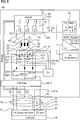
Das Fahrzeugbordnetz FBN ist von einer Ladestation Lad über einen Stecker Stk mit Gleichstrom DC und/oder einphasigem Wechselstrom AC und/oder dreiphasigem Wechselstrom (Drehstrom) AC ladbar und/oder induktiv IND über Induktivladespulen Ind-Pri-coil, Ind-Sek-Coil ladbar. Es sind z.B. Schalteinrichtungen SW1, SW2, SW3, SWN; SP1, SP2 einer Schalteinrichtung SW-Box zum Steuern insbesondere des Ladens des zu ladenden Energiespeichers ES (über z.B. einen Filter EMV-F und/oder eine elektrische Maschine EM und/oder einen Wechselrichter WR) dargestellt. The vehicle electrical system FBN can be charged from a charging station Lad via a plug Stk with direct current DC and / or single-phase alternating current AC and / or three-phase alternating current (AC) AC and / or inductive IND via inductive charging coils Ind-Pri-coil, Ind-Sek-Coil , They are e.g. Switching devices SW1, SW2, SW3, SWN; SP1, SP2 of a switching device SW box for controlling, in particular, the charging of the energy store ES to be charged (via, for example, a filter EMC-F and / or an electric machine EM and / or an inverter WR).
Das in
In
Zum Stabilisieren eines privaten Energienetzes NetPriv und/oder eines öffentlichen Energienetz NetPub ist vom Energiespeicher ES (z.B. nach Mitteilung Anf-R und/oder Feststellung durch eine Sensorik) Energie induktiv über Spulen Ind-Sek-Coil, Ind-Pri-Coil und eine Ladeeinrichtung Lad in das private Energienetz NetPriv und/oder in das öffentliche Energienetz NetPub übertragbar (angedeutet durch den Pfeil Ind-Entlad-Ueb in
Zum Stabilisieren eines privaten Energienetzes NetPriv und/oder eines öffentlichen Energienetz NetPub ist vom Energiespeicher ES (z.B. nach Mitteilung Anf-R und/oder Feststellung durch eine Sensorik) alternativ auch Energie drahtgebunden (galvanisch) über den Stecker Stk und eine Ladeeinrichtung Lad in das private Energienetz NetPriv und/oder öffentliche Energienetz NetPub übertragbar (angedeutet durch den Pfeil Entlad-Ueb in
Der elektrische Energiespeicher ES des Fahrzeugbordnetzes FBN kann (z.B. über den Inverter WR und/oder eine elektrische Maschine (Motor EM) und/oder Filter EMV-F) induktiv geladen werden, indem mit mindestens einer von einer Steuerung Ctrl gesteuerten Schalteinrichtung SWN, SW3 mindestens ein Phasenstromanschluss PS1, PS3 des Wechselrichters WR mit einem Induktiv-Ladespulen-Anschluss Ind1, Ind2 einer Induktiv-Lade-Sekundärspule Ind-Sek-Coil (seitens des Fahrzeugbordnetzes und/oder Fahrzeuges Kfz) verbunden wird. Es kann dabei mit mindestens einer von einer Steuerung Ctrl gesteuerten Schalteinrichtung SWN, SW3 mindestens ein (oder zwei) der Phasenstromanschlüsse PS1; PS3; PS1, PS3 des Wechselrichters WR über je einen Motorklemmen-Anschluss A1; A3 mit einem Induktiv-Ladespulen-Anschluss Ind1; Ind2; Ind1, Ind2 der Induktiv-Lade-Sekundärspule Ind-Sek-Coil verbunden werden, und zwar z.B. direkt wie in
Eine von einer Steuerung Ctrl gesteuerte Schalteinrichtung SWN, SW3 zum Schalten insbesondere eines oder beider der Induktiv-Ladespulen-Anschlüsse Ind1, Ind2 kann unterschiedlich angeordnet sein:
Möglich ist z.B.
- – mindestens eine von einer Steuerung Ctrl gesteuerte Schalteinrichtung SWN, SW3 deren eine Seite zwischen jeweils einem Phasenstromanschluss PS1, PS3 des Wechselrichters WR und einer äußeren Motorphase U2, V2, W2 der elektrischen Maschine EM angeschlossen ist, um dort einen mit ihrer andere Seite verbundenen Induktiv-Ladespulen-Anschluss Ind1; Ind2; Ind1, Ind2 einer Induktiv-Lade-Sekundärspule Ind-Sek-Coil anzuschalten,
- – mindestens eine von einer Steuerung Ctrl gesteuerte Schalteinrichtung SWN, SW3 deren eine Seite zwischen einer Motorphase U2, V2, W2 der elektrischen Maschine EM und einem der Lade-Eingänge N; AC1, AC2, AC3; DC+, DC– des Fahrzeugbordnetzes FBN angeschlossen ist, um dort einen mit ihrer andere Seite verbundenen Induktiv-Ladespulen-Anschluss Ind1; Ind2; Ind1, Ind2 einer Induktiv-Lade-Sekundärspule Ind-Sek-Coil anzuschalten,
- – mindestens eine von einer Steuerung Ctrl gesteuerte Schalteinrichtung SWN, SW3 deren eine Seite zwischen einem Phasenstromanschluss PS1, PS3 des Wechselrichters WR und und einem der Lade-Eingänge N; AC1, AC2, AC3; DC+, DC– des Fahrzeugbordnetzes FBN angeschlossen ist, um dort einen mit ihrer andere Seite verbundenen Induktiv-Ladespulen-Anschluss Ind1; Ind2; Ind1, Ind2 einer Induktiv-Lade-Sekundärspule Ind-Sek-Coil anzuschalten,
- – mindestens eine von einer Steuerung Ctrl gesteuerte Schalteinrichtung SWN, SW3 deren eine Seite zwischen einem Phasenstromanschluss PS1, PS3 des Wechselrichters WR und und einem Filter EMV-F an einem der Lade-Eingänge N; AC1, AC2, AC3; DC+, DC– des Fahrzeugbordnetzes FBN angeschlossen ist, um dort einen mit ihrer andere Seite verbundenen Induktiv-Ladespulen-Anschluss Ind1; Ind2; Ind1, Ind2 einer Induktiv-Lade-Sekundärspule Ind-Sek-Coil anzuschalten,
- – mindestens eine von einer Steuerung Ctrl gesteuerte Schalteinrichtung SWN, SW3 deren eine Seite zwischen einem Filter EMV-F und einem der Lade-Eingänge N; AC1, AC2, AC3; DC+, DC– des Fahrzeugbordnetzes FBN angeschlossen ist, um dort einen mit ihrer andere Seite verbundenen Induktiv-Ladespulen-Anschluss Ind1; Ind2; Ind1, Ind2 einer Induktiv-Lade-Sekundärspule Ind-Sek-Coil anzuschalten.
Possible, for example
- At least one switching device SWN, SW3 controlled by a controller Ctrl whose one side is connected between in each case one phase current connection PS1, PS3 of the inverter WR and an external motor phase U2, V2, W2 of the electrical machine EM, there around an inductive charging coil terminal Ind1 connected to its other side; ind2; Ind1, Ind2 of an inductive charging secondary coil Ind-Sek-Coil,
- - At least one controlled by a controller Ctrl switching device SWN, SW3 whose one side between a motor phase U2, V2, W2 of the electric machine EM and one of the charging inputs N; AC1, AC2, AC3; DC +, DC- of the vehicle electrical system FBN is connected to there is connected to its other side inductive charging coil terminal Ind1; ind2; Ind1, Ind2 of an inductive charging secondary coil Ind-Sek-Coil,
- - At least one controlled by a controller Ctrl switching device SWN, SW3 whose one side between a phase current terminal PS1, PS3 of the inverter WR and one of the load inputs N; AC1, AC2, AC3; DC +, DC- of the vehicle electrical system FBN is connected to there is connected to its other side inductive charging coil terminal Ind1; ind2; Ind1, Ind2 of an inductive charging secondary coil Ind-Sek-Coil,
- - At least one controlled by a controller Ctrl switching device SWN, SW3 whose one side between a phase current terminal PS1, PS3 of the inverter WR and a filter EMV-F at one of the load inputs N; AC1, AC2, AC3; DC +, DC- of the vehicle electrical system FBN is connected to there is connected to its other side inductive charging coil terminal Ind1; ind2; Ind1, Ind2 of an inductive charging secondary coil Ind-Sek-Coil,
- - At least one controlled by a controller Ctrl switching device SWN, SW3 whose one side between a filter EMV-F and one of the load inputs N; AC1, AC2, AC3; DC +, DC- of the vehicle electrical system FBN is connected to there is connected to its other side inductive charging coil terminal Ind1; ind2; Ind1, Ind2 of an induction charging secondary coil Ind-Sek-Coil.
Mit einer von einer Steuerung Ctrl gesteuerte Schalteinrichtung SWN, SW3 kann z.B. jeweils ein Motorklemmen-Anschluss A1; A3 einer inneren Motorphase U2, V2, W2 der elektrischen Maschine EM mit einem Induktiv-Ladespulen-Anschluss Ind1, Ind2 einer Induktiv-Lade-Sekundärspule Ind-Sek-Coil verbindbar sein, oder ein Motorklemmen-Anschluss A1; A3 einer äußeren Motorphase U1, V1, W1 der elektrischen Maschine EM mit einem Induktiv-Ladespulen-Anschluss Ind1, Ind2 einer Induktiv-Lade-Sekundärspule Ind-Sek-Coil verbindbar sein. With a control device SWN, SW3 controlled by a controller Ctrl, e.g. one motor terminal A1 each; A3 of an internal motor phase U2, V2, W2 of the electric machine EM be connectable to an inductive charging coil terminal Ind1, Ind2 of an inductive charging secondary coil Ind-sec coil, or a motor terminal terminal A1; A3 of an outer motor phase U1, V1, W1 of the electric machine EM with an inductive charging coil terminal Ind1, Ind2 an inductive charging secondary coil Ind-sec coil be connectable.
Nach einer Ausgestaltung der Erfindung umfasst das in den Fig. gezeigte Fahrzeugbordnetz FBN
- – einen elektrischen Energiespeicher ES,
- – einen Wechselrichter WR,
- – eine elektrischen Maschine EM,
wobei auf der ersten Seite S1 des Wechselrichters WR zwei Ausgangsanschlüsse EA1, EA2 des Wechselrichters WR mit dem Energiespeicher ES verbunden oder verbindbar sind,
wobei auf der zweiten Seite S2 des Wechselrichters WR mindestens zwei Phasenstromanschlüsse PS1, PS2, PS3 des Wechselrichters WR mit der elektrischen Maschine EM verbunden oder verbindbar sind,
wobei durch eine von einer Steuerung Ctrl gesteuerte Schalteinrichtung SW1, SW2, SW3, SWN; SP1, SP2; SW-Box mindestens einer der Lade-Eingänge N; AC1, AC2, AC3; DC+, DC–, Ind1, Ind2 des Fahrzeugbordnetzes FBN jeweils auf eine innere Motorphase U2, V2, W2 der elektrischen Maschine EM schaltbar ist. According to one embodiment of the invention, the vehicle electrical system FBN shown in FIGS
- An electrical energy store ES,
- An inverter WR,
- - an electric machine EM,
wherein on the first side S1 of the inverter WR two output terminals EA1, EA2 of the inverter WR are connected or connectable to the energy store ES,
wherein at least two phase current connections PS1, PS2, PS3 of the inverter WR are connected or connectable to the electric machine EM on the second side S2 of the inverter WR,
wherein switching means SW1, SW2, SW3, SWN controlled by a controller Ctrl; SP1, SP2; SW box at least one of the load inputs N; AC1, AC2, AC3; DC +, DC-, Ind1, Ind2 of the vehicle electrical system FBN in each case to an inner engine phase U2, V2, W2 of the electric machine EM is switchable.
Das Fahrzeugbordnetz FBN und(oder die Ladestation Lad kann eine Steuerung Ctrl, Ctrl-Lad und/oder Sensorik und/oder Kommunikationsverbindung PP, CP und/oder Schalteinrichtungen aufweisen, die jeweils soweit vorhanden dazu ausgebildet ist bzw. sind, dass ein zu einem induktiven Laden IND des Energiespeichers ES gleichzeitiges galvanisches Laden des Energiespeichers ES des Fahrzeugbordnetzes FBN mit einphasigem oder dreiphasigen Wechselstrom vermieden ist,
und/oder dass ein zu einem induktiven Laden IND des Energiespeichers ES gleichzeitiges galvanisches Laden des Energiespeichers ES des Fahrzeugbordnetzes FBN mit Gleichstrom DC vermieden ist,
und/oder dass ein zu einem galvanischen Laden des Energiespeichers ES des Fahrzeugbordnetzes FBN mit einphasigem oder dreiphasigen Wechselstrom gleichzeitiges galvanisches Laden des Energiespeichers ES des Fahrzeugbordnetzes FBN mit Gleichstrom DC vermieden ist. The vehicle electrical system FBN and (or the charging station Lad may include a controller Ctrl, Ctrl-Lad and / or sensor and / or communication link PP, CP and / or switching devices, which is each formed as far as available to or that one to an inductive Charging IND of the energy storage ES simultaneous galvanic charging of the energy storage ES of the vehicle electrical system FBN with single-phase or three-phase alternating current is avoided,
and / or that a galvanic charging of the energy store ES of the vehicle electrical system FBN with direct current DC, which is simultaneous with an inductive charging IND of the energy store ES, is avoided,
and / or that a galvanic charging of the energy store ES of the vehicle electrical system FBN with direct current DC is simultaneously avoided for a galvanic charging of the energy store ES of the vehicle electrical system FBN with single-phase or three-phase alternating current.
ZITATE ENTHALTEN IN DER BESCHREIBUNG QUOTES INCLUDE IN THE DESCRIPTION
Diese Liste der vom Anmelder aufgeführten Dokumente wurde automatisiert erzeugt und ist ausschließlich zur besseren Information des Lesers aufgenommen. Die Liste ist nicht Bestandteil der deutschen Patent- bzw. Gebrauchsmusteranmeldung. Das DPMA übernimmt keinerlei Haftung für etwaige Fehler oder Auslassungen.This list of the documents listed by the applicant has been generated automatically and is included solely for the better information of the reader. The list is not part of the German patent or utility model application. The DPMA assumes no liability for any errors or omissions.
Zitierte PatentliteraturCited patent literature
- DE 102016213054 [0001, 0004, 0005, 0006, 0007] DE 102016213054 [0001, 0004, 0005, 0006, 0007]
Claims (24)
Priority Applications (2)
| Application Number | Priority Date | Filing Date | Title |
|---|---|---|---|
| DE102016215504.0A DE102016215504A1 (en) | 2016-08-18 | 2016-08-18 | Vehicle electrical system and procedure |
| PCT/EP2017/069321 WO2018033377A1 (en) | 2016-08-18 | 2017-07-31 | Vehicle electrical system for inductively charging an electric vehicle and method |
Applications Claiming Priority (1)
| Application Number | Priority Date | Filing Date | Title |
|---|---|---|---|
| DE102016215504.0A DE102016215504A1 (en) | 2016-08-18 | 2016-08-18 | Vehicle electrical system and procedure |
Publications (1)
| Publication Number | Publication Date |
|---|---|
| DE102016215504A1 true DE102016215504A1 (en) | 2018-02-22 |
Family
ID=59485357
Family Applications (1)
| Application Number | Title | Priority Date | Filing Date |
|---|---|---|---|
| DE102016215504.0A Ceased DE102016215504A1 (en) | 2016-08-18 | 2016-08-18 | Vehicle electrical system and procedure |
Country Status (2)
| Country | Link |
|---|---|
| DE (1) | DE102016215504A1 (en) |
| WO (1) | WO2018033377A1 (en) |
Families Citing this family (1)
| Publication number | Priority date | Publication date | Assignee | Title |
|---|---|---|---|---|
| DE102020119108A1 (en) | 2020-07-21 | 2022-01-27 | Dr. Ing. H.C. F. Porsche Aktiengesellschaft | DC filter device |
Citations (4)
| Publication number | Priority date | Publication date | Assignee | Title |
|---|---|---|---|---|
| WO2011063006A1 (en) * | 2009-11-17 | 2011-05-26 | Aerovironment, Inc. | Integrated motor drive and battery charging system |
| US20140042807A1 (en) * | 2011-04-08 | 2014-02-13 | Valeo Systemes De Controle Moteur | Charge transfer device and associated management method |
| DE102013217574A1 (en) * | 2012-09-05 | 2014-04-30 | Lear Corporation | Multi-mode battery charger |
| DE102016213054B3 (en) | 2016-07-18 | 2017-04-27 | Continental Automotive Gmbh | Vehicle electrical system and procedure |
Family Cites Families (6)
| Publication number | Priority date | Publication date | Assignee | Title |
|---|---|---|---|---|
| US20120032633A1 (en) * | 2009-04-09 | 2012-02-09 | Ralf Cordes | Transmission of power bidirectionally and without contact to charge electric vehicles |
| AT510025B1 (en) * | 2010-06-02 | 2012-01-15 | Siemens Ag | DRIVE UNIT OF AN ELECTRIC VEHICLE |
| DE102010055933A1 (en) * | 2010-12-23 | 2012-06-28 | Daimler Ag | Vehicle device |
| DE102011083020A1 (en) * | 2011-09-20 | 2013-03-21 | Robert Bosch Gmbh | Loading device, in particular for motor vehicles, methods and motor vehicle |
| JP6024106B2 (en) * | 2011-12-27 | 2016-11-09 | 株式会社Ihi | Transfer device and mobile vehicle |
| DE102012220371A1 (en) * | 2012-11-08 | 2014-05-08 | Robert Bosch Gmbh | Device for charging high voltage battery of electric vehicle from three-phase alternating current voltage source, has switch switched by control device such that current and voltage of source are in phase with each other |
-
2016
- 2016-08-18 DE DE102016215504.0A patent/DE102016215504A1/en not_active Ceased
-
2017
- 2017-07-31 WO PCT/EP2017/069321 patent/WO2018033377A1/en not_active Ceased
Patent Citations (4)
| Publication number | Priority date | Publication date | Assignee | Title |
|---|---|---|---|---|
| WO2011063006A1 (en) * | 2009-11-17 | 2011-05-26 | Aerovironment, Inc. | Integrated motor drive and battery charging system |
| US20140042807A1 (en) * | 2011-04-08 | 2014-02-13 | Valeo Systemes De Controle Moteur | Charge transfer device and associated management method |
| DE102013217574A1 (en) * | 2012-09-05 | 2014-04-30 | Lear Corporation | Multi-mode battery charger |
| DE102016213054B3 (en) | 2016-07-18 | 2017-04-27 | Continental Automotive Gmbh | Vehicle electrical system and procedure |
Also Published As
| Publication number | Publication date |
|---|---|
| WO2018033377A1 (en) | 2018-02-22 |
Similar Documents
| Publication | Publication Date | Title |
|---|---|---|
| EP3485555B1 (en) | On-board vehicle electrical system for charging an electrically operated vehicle, and coresponding method | |
| EP3189575B1 (en) | Device for charging an energy store | |
| DE102021131658A1 (en) | VEHICLE ON-BOARD NETWORK WITH AN INVERTER AND AN ELECTRIC MOTOR FOR VOLTAGE INCREASE | |
| DE102017105993A1 (en) | CHARGING SYSTEM FOR VEHICLE BATTERY | |
| DE102015102517B4 (en) | Vehicle with a charging system for a battery | |
| DE102011056516A1 (en) | Power supply device for vehicles | |
| DE102009007737A1 (en) | Energy converter device for battery charger of electrical hybrid vehicle, has three connections, where energy is transferable from first to second and/or third connection, from second to third connection or from third to second connection | |
| DE102018112622A1 (en) | Charging system, charging method and charging system | |
| DE102016206945A1 (en) | Combined multilevel inverter and ACDC power charging unit | |
| DE102017008840A1 (en) | Electric vehicle electrical system | |
| DE102012201827A1 (en) | Method and device for discharging a DC link of a voltage network | |
| DE102013011104A1 (en) | Electrical power distribution device for an electrically driven vehicle and method for operating the power distribution device | |
| DE102011076599A1 (en) | Electric charging system | |
| DE102017212496A1 (en) | High-voltage battery device and method for operating a high-voltage battery device | |
| DE102016015314A1 (en) | Electric drive system for a vehicle and method of operation thereof | |
| DE102016002459A1 (en) | Electrical system for an electrically driven motor vehicle | |
| DE102016213054B3 (en) | Vehicle electrical system and procedure | |
| DE102018129413A1 (en) | Method and system for integrating a charging peripheral control into a galvanically non-isolated charger | |
| DE102016215504A1 (en) | Vehicle electrical system and procedure | |
| DE102019206502A1 (en) | Switching device for charging the battery of an electric vehicle at present and future DC charging infrastructures and a method for operating the switching device | |
| DE102017201350B4 (en) | Method for transmitting electrical energy between a vehicle-side energy storage and a connection station and vehicle electrical system | |
| DE102016012876A1 (en) | Electric drive system for a vehicle | |
| DE102016215294A1 (en) | Vehicle electrical system, motor vehicle and method | |
| DE102023116904A1 (en) | Electric machine unit, vehicle and method for operating an electric machine unit | |
| EP3759787B1 (en) | Charging system |
Legal Events
| Date | Code | Title | Description |
|---|---|---|---|
| R012 | Request for examination validly filed | ||
| R016 | Response to examination communication | ||
| R079 | Amendment of ipc main class |
Free format text: PREVIOUS MAIN CLASS: B60L0011180000 Ipc: B60L0053200000 |
|
| R081 | Change of applicant/patentee |
Owner name: VITESCO TECHNOLOGIES GMBH, DE Free format text: FORMER OWNER: CONTINENTAL AUTOMOTIVE GMBH, 30165 HANNOVER, DE |
|
| R081 | Change of applicant/patentee |
Owner name: VITESCO TECHNOLOGIES GMBH, DE Free format text: FORMER OWNER: VITESCO TECHNOLOGIES GMBH, 30165 HANNOVER, DE |
|
| R002 | Refusal decision in examination/registration proceedings | ||
| R003 | Refusal decision now final |