DE102016212951A1 - Direct-injection spark-ignition internal combustion engine with injection device arranged in the cylinder tube and method for operating such an internal combustion engine - Google Patents
Direct-injection spark-ignition internal combustion engine with injection device arranged in the cylinder tube and method for operating such an internal combustion engine Download PDFInfo
- Publication number
- DE102016212951A1 DE102016212951A1 DE102016212951.1A DE102016212951A DE102016212951A1 DE 102016212951 A1 DE102016212951 A1 DE 102016212951A1 DE 102016212951 A DE102016212951 A DE 102016212951A DE 102016212951 A1 DE102016212951 A1 DE 102016212951A1
- Authority
- DE
- Germany
- Prior art keywords
- cylinder
- internal combustion
- combustion engine
- fuel
- injection device
- Prior art date
- Legal status (The legal status is an assumption and is not a legal conclusion. Google has not performed a legal analysis and makes no representation as to the accuracy of the status listed.)
- Ceased
Links
Images
Classifications
-
- F—MECHANICAL ENGINEERING; LIGHTING; HEATING; WEAPONS; BLASTING
- F02—COMBUSTION ENGINES; HOT-GAS OR COMBUSTION-PRODUCT ENGINE PLANTS
- F02D—CONTROLLING COMBUSTION ENGINES
- F02D41/00—Electrical control of supply of combustible mixture or its constituents
- F02D41/30—Controlling fuel injection
- F02D41/38—Controlling fuel injection of the high pressure type
- F02D41/40—Controlling fuel injection of the high pressure type with means for controlling injection timing or duration
- F02D41/402—Multiple injections
-
- F—MECHANICAL ENGINEERING; LIGHTING; HEATING; WEAPONS; BLASTING
- F02—COMBUSTION ENGINES; HOT-GAS OR COMBUSTION-PRODUCT ENGINE PLANTS
- F02B—INTERNAL-COMBUSTION PISTON ENGINES; COMBUSTION ENGINES IN GENERAL
- F02B23/00—Other engines characterised by special shape or construction of combustion chambers to improve operation
- F02B23/08—Other engines characterised by special shape or construction of combustion chambers to improve operation with positive ignition
-
- F—MECHANICAL ENGINEERING; LIGHTING; HEATING; WEAPONS; BLASTING
- F02—COMBUSTION ENGINES; HOT-GAS OR COMBUSTION-PRODUCT ENGINE PLANTS
- F02D—CONTROLLING COMBUSTION ENGINES
- F02D41/00—Electrical control of supply of combustible mixture or its constituents
- F02D41/30—Controlling fuel injection
- F02D41/3094—Controlling fuel injection the fuel injection being effected by at least two different injectors, e.g. one in the intake manifold and one in the cylinder
-
- F—MECHANICAL ENGINEERING; LIGHTING; HEATING; WEAPONS; BLASTING
- F02—COMBUSTION ENGINES; HOT-GAS OR COMBUSTION-PRODUCT ENGINE PLANTS
- F02D—CONTROLLING COMBUSTION ENGINES
- F02D41/00—Electrical control of supply of combustible mixture or its constituents
- F02D41/30—Controlling fuel injection
- F02D41/38—Controlling fuel injection of the high pressure type
- F02D41/3809—Common rail control systems
- F02D41/3836—Controlling the fuel pressure
-
- F—MECHANICAL ENGINEERING; LIGHTING; HEATING; WEAPONS; BLASTING
- F02—COMBUSTION ENGINES; HOT-GAS OR COMBUSTION-PRODUCT ENGINE PLANTS
- F02F—CYLINDERS, PISTONS OR CASINGS, FOR COMBUSTION ENGINES; ARRANGEMENTS OF SEALINGS IN COMBUSTION ENGINES
- F02F1/00—Cylinders; Cylinder heads
- F02F1/004—Cylinder liners
-
- F—MECHANICAL ENGINEERING; LIGHTING; HEATING; WEAPONS; BLASTING
- F02—COMBUSTION ENGINES; HOT-GAS OR COMBUSTION-PRODUCT ENGINE PLANTS
- F02F—CYLINDERS, PISTONS OR CASINGS, FOR COMBUSTION ENGINES; ARRANGEMENTS OF SEALINGS IN COMBUSTION ENGINES
- F02F3/00—Pistons
-
- F—MECHANICAL ENGINEERING; LIGHTING; HEATING; WEAPONS; BLASTING
- F02—COMBUSTION ENGINES; HOT-GAS OR COMBUSTION-PRODUCT ENGINE PLANTS
- F02M—SUPPLYING COMBUSTION ENGINES IN GENERAL WITH COMBUSTIBLE MIXTURES OR CONSTITUENTS THEREOF
- F02M61/00—Fuel-injectors not provided for in groups F02M39/00 - F02M57/00 or F02M67/00
- F02M61/14—Arrangements of injectors with respect to engines; Mounting of injectors
-
- F—MECHANICAL ENGINEERING; LIGHTING; HEATING; WEAPONS; BLASTING
- F02—COMBUSTION ENGINES; HOT-GAS OR COMBUSTION-PRODUCT ENGINE PLANTS
- F02B—INTERNAL-COMBUSTION PISTON ENGINES; COMBUSTION ENGINES IN GENERAL
- F02B23/00—Other engines characterised by special shape or construction of combustion chambers to improve operation
- F02B23/08—Other engines characterised by special shape or construction of combustion chambers to improve operation with positive ignition
- F02B2023/085—Other engines characterised by special shape or construction of combustion chambers to improve operation with positive ignition using several spark plugs per cylinder
-
- F—MECHANICAL ENGINEERING; LIGHTING; HEATING; WEAPONS; BLASTING
- F02—COMBUSTION ENGINES; HOT-GAS OR COMBUSTION-PRODUCT ENGINE PLANTS
- F02D—CONTROLLING COMBUSTION ENGINES
- F02D41/00—Electrical control of supply of combustible mixture or its constituents
- F02D41/30—Controlling fuel injection
- F02D41/38—Controlling fuel injection of the high pressure type
- F02D41/3809—Common rail control systems
- F02D2041/3881—Common rail control systems with multiple common rails, e.g. one rail per cylinder bank, or a high pressure rail and a low pressure rail
-
- F—MECHANICAL ENGINEERING; LIGHTING; HEATING; WEAPONS; BLASTING
- F02—COMBUSTION ENGINES; HOT-GAS OR COMBUSTION-PRODUCT ENGINE PLANTS
- F02D—CONTROLLING COMBUSTION ENGINES
- F02D41/00—Electrical control of supply of combustible mixture or its constituents
- F02D41/30—Controlling fuel injection
- F02D41/38—Controlling fuel injection of the high pressure type
- F02D2041/389—Controlling fuel injection of the high pressure type for injecting directly into the cylinder
-
- F—MECHANICAL ENGINEERING; LIGHTING; HEATING; WEAPONS; BLASTING
- F02—COMBUSTION ENGINES; HOT-GAS OR COMBUSTION-PRODUCT ENGINE PLANTS
- F02D—CONTROLLING COMBUSTION ENGINES
- F02D2200/00—Input parameters for engine control
- F02D2200/02—Input parameters for engine control the parameters being related to the engine
- F02D2200/024—Fluid pressure of lubricating oil or working fluid
-
- F—MECHANICAL ENGINEERING; LIGHTING; HEATING; WEAPONS; BLASTING
- F02—COMBUSTION ENGINES; HOT-GAS OR COMBUSTION-PRODUCT ENGINE PLANTS
- F02D—CONTROLLING COMBUSTION ENGINES
- F02D2200/00—Input parameters for engine control
- F02D2200/02—Input parameters for engine control the parameters being related to the engine
- F02D2200/10—Parameters related to the engine output, e.g. engine torque or engine speed
- F02D2200/1002—Output torque
-
- F—MECHANICAL ENGINEERING; LIGHTING; HEATING; WEAPONS; BLASTING
- F02—COMBUSTION ENGINES; HOT-GAS OR COMBUSTION-PRODUCT ENGINE PLANTS
- F02D—CONTROLLING COMBUSTION ENGINES
- F02D2200/00—Input parameters for engine control
- F02D2200/02—Input parameters for engine control the parameters being related to the engine
- F02D2200/10—Parameters related to the engine output, e.g. engine torque or engine speed
- F02D2200/101—Engine speed
-
- F—MECHANICAL ENGINEERING; LIGHTING; HEATING; WEAPONS; BLASTING
- F02—COMBUSTION ENGINES; HOT-GAS OR COMBUSTION-PRODUCT ENGINE PLANTS
- F02F—CYLINDERS, PISTONS OR CASINGS, FOR COMBUSTION ENGINES; ARRANGEMENTS OF SEALINGS IN COMBUSTION ENGINES
- F02F1/00—Cylinders; Cylinder heads
- F02F1/24—Cylinder heads
- F02F1/242—Arrangement of spark plugs or injectors
-
- Y—GENERAL TAGGING OF NEW TECHNOLOGICAL DEVELOPMENTS; GENERAL TAGGING OF CROSS-SECTIONAL TECHNOLOGIES SPANNING OVER SEVERAL SECTIONS OF THE IPC; TECHNICAL SUBJECTS COVERED BY FORMER USPC CROSS-REFERENCE ART COLLECTIONS [XRACs] AND DIGESTS
- Y02—TECHNOLOGIES OR APPLICATIONS FOR MITIGATION OR ADAPTATION AGAINST CLIMATE CHANGE
- Y02T—CLIMATE CHANGE MITIGATION TECHNOLOGIES RELATED TO TRANSPORTATION
- Y02T10/00—Road transport of goods or passengers
- Y02T10/10—Internal combustion engine [ICE] based vehicles
- Y02T10/12—Improving ICE efficiencies
Landscapes
- Engineering & Computer Science (AREA)
- Chemical & Material Sciences (AREA)
- Combustion & Propulsion (AREA)
- Mechanical Engineering (AREA)
- General Engineering & Computer Science (AREA)
- Combustion Methods Of Internal-Combustion Engines (AREA)
- Electrical Control Of Air Or Fuel Supplied To Internal-Combustion Engine (AREA)
- Fuel-Injection Apparatus (AREA)
Abstract
Direkteinspritzende fremdgezündete Brennkraftmaschine mit mindestens einem Zylinder (1), bei der – jeder Zylinder (1) mindestens eine Einlassöffnung (7) zum Zuführen von Verbrennungsluft via Ansaugsystem und mindestens eine Auslassöffnung (8) zum Abführen der Abgase via Abgasabführsystem aufweist, – jeder Zylinder (1) einen Brennraum (2) umfasst, der durch ein den Brennraum (2) seitlich begrenzendes Zylinderrohr (4) mit ausgebildet ist, und – jeder Zylinder (1) in einem Bereich des Zylinderrohres (4) mit einer Einspritzvorrichtung (6) zum direkten Einbringen von Kraftstoff in den Brennraum (2) ausgestattet ist, die über mindestens eine Öffnung verfügt, welche im Rahmen eines Einspritzvorganges zwecks Einbringens von Kraftstoff in den Brennraum (2) aktivierbar ist dadurch gekennzeichnet, dass – jeder Zylinder (1) mit einer zusätzlichen Einspritzvorrichtung (9) ausgestattet ist, die im zylinderzugehörigen Zylinderkopf (3) angeordnet ist, wobei die Einspritzvorrichtung (6) auf die zusätzliche Einspritzvorrichtung (9) ausgerichtet ist, in der Art, dass eine virtuelle Verlängerung (6c) einer Längsachse (6c) der Einspritzvorrichtung (6) mit einer virtuellen Verlängerung (9c) einer Längsachse (9c) der zusätzlichen Einspritzvorrichtung (9) in einer Projektion senkrecht zur Kolbenlängsachse (5b) einen stumpfen Winkel α bildet.Direct injection spark-ignited internal combustion engine having at least one cylinder (1), in which - each cylinder (1) has at least one inlet opening (7) for supplying combustion air via the intake system and at least one outlet opening (8) for discharging the exhaust gases via the exhaust removal system, - 1) comprises a combustion chamber (2) formed by a cylinder tube (4) laterally delimiting the combustion chamber (2), and - each cylinder (1) in an area of the cylinder tube (4) with an injection device (6) for direct injection Introducing fuel into the combustion chamber (2) is equipped, which has at least one opening which is activated in the context of an injection process for the purpose of introducing fuel into the combustion chamber (2), characterized in that - each cylinder (1) with an additional injection device (9) which is arranged in the cylinder-associated cylinder head (3), wherein the injection device (6) is aligned with the additional injection device (9) such that a virtual extension (6c) of a longitudinal axis (6c) of the injection device (6) with a virtual extension (9c) of a longitudinal axis (9c) of the additional injection device (9c) 9) in a projection perpendicular to the piston longitudinal axis (5b) forms an obtuse angle α.
Description
Die Erfindung betrifft eine direkteinspritzende fremdgezündete Brennkraftmaschine mit mindestens einem Zylinderkopf umfassend mindestens einen Zylinder, bei der
- – jeder Zylinder mindestens eine Einlassöffnung zum Zuführen von Verbrennungsluft via Ansaugsystem und mindestens eine Auslassöffnung zum Abführen der Abgase via Abgasabführsystem aufweist,
- – jeder Zylinder einen Brennraum umfasst, der durch einen Kolbenboden eines zylinderzugehörigen Kolbens, ein den Brennraum seitlich begrenzendes Zylinderrohr und den mindestens einen Zylinderkopf mit ausgebildet ist, wobei der Kolben entlang einer Kolbenlängsachse zwischen einem unteren Totpunkt und einem oberen Totpunkt bewegbar ist, und
- – jeder Zylinder in einem Bereich des Zylinderrohres mit einer Einspritzvorrichtung zum direkten Einbringen von Kraftstoff in den Brennraum ausgestattet ist, die über mindestens eine Öffnung verfügt, welche im Rahmen eines Einspritzvorganges zwecks Einbringens von Kraftstoff in den Brennraum aktivierbar ist.
- Each cylinder has at least one inlet opening for supplying combustion air via the intake system and at least one outlet opening for discharging the exhaust gases via the exhaust removal system,
- - Each cylinder comprises a combustion chamber which is formed by a piston head of a cylinder-associated piston, a combustion chamber, the laterally delimiting cylinder tube and the at least one cylinder head, wherein the piston along a piston longitudinal axis between a bottom dead center and a top dead center is movable, and
- - Each cylinder is provided in an area of the cylinder tube with an injection device for directly introducing fuel into the combustion chamber, which has at least one opening which can be activated in the context of an injection process for the purpose of introducing fuel into the combustion chamber.
Des Weiteren betrifft die Erfindung ein Verfahren zum Betreiben einer derartigen Brennkraftmaschine.Furthermore, the invention relates to a method for operating such an internal combustion engine.
Eine Brennkraftmaschine der genannten Art wird als Kraftfahrzeugantrieb eingesetzt. Im Rahmen der vorliegenden Erfindung umfasst der Begriff Brennkraftmaschine fremdgezündete Ottomotoren, aber auch fremdgezündete Hybrid-Brennkraftmaschinen, d. h. fremdgezündete Brennkraftmaschinen, die mit einem Hybrid-Brennverfahren betrieben werden, sowie Hybrid-Antriebe, die neben der fremdgezündeten Brennkraftmaschine eine mit der Brennkraftmaschine antriebsverbindbare Elektromaschine umfassen, welche Leistung von der Brennkraftmaschine aufnimmt oder als zuschaltbarer Hilfsantrieb zusätzlich Leistung abgibt.An internal combustion engine of the type mentioned is used as a motor vehicle drive. In the context of the present invention, the term internal combustion engine includes spark ignited gasoline engines, but also spark ignited hybrid internal combustion engines, d. H. spark-ignition internal combustion engines, which are operated with a hybrid combustion method, and hybrid drives, which include in addition to the spark-ignition internal combustion engine drive-connected with the electric motor, which receives power from the engine or emits additional power as a switchable auxiliary drive.
Brennkraftmaschinen verfügen über einen Zylinderblock und mindestens einen Zylinderkopf, die zur Ausbildung der Zylinder und deren Brennräume miteinander verbunden werden bzw. sind. Der Zylinderblock dient regelmäßig als obere Kurbelgehäusehälfte zur Lagerung der Kurbelwelle und zur Aufnahme des Kolbens bzw. der Zylinderlaufbuchse jedes Zylinders. Der Kolben kann auch unter Weglassen einer Buchse als Zwischenelement direkt in einer Bohrung des Blocks gelagert und geführt sein. Im Rahmen der vorliegenden Erfindung wird sowohl die Zylinderlaufbuchse als auch die Bohrung unter den Begriff Zylinderrohr subsumiert.Internal combustion engines have a cylinder block and at least one cylinder head, which are connected to form the cylinders and their combustion chambers with each other or are. The cylinder block is used regularly as an upper crankcase half for supporting the crankshaft and for receiving the piston or the cylinder liner of each cylinder. The piston can also be stored and guided by omitting a bush as an intermediate element directly in a bore of the block. In the context of the present invention, both the cylinder liner and the bore are subsumed under the term cylinder tube.
Der Zylinderkopf dient üblicherweise zur Aufnahme der für den Ladungswechsel erforderlichen Ventiltriebe. Im Rahmen des Ladungswechsels erfolgt das Abführen der Verbrennungsgase via Abgasabführsystem über die mindestens eine Auslassöffnung und das Zuführen der Verbrennungsluft via Ansaugsystem über die mindestens eine Einlassöffnung des Zylinders. Nach dem Stand der Technik werden bei Viertaktmotoren zur Steuerung des Ladungswechsels nahezu ausschließlich Hubventile verwendet. Das Ventil einschließlich des zugehörigen Betätigungsmechanismus wird als Ventiltrieb bezeichnet.The cylinder head usually serves to accommodate the valve trains required for the charge cycle. As part of the charge exchange, the discharge of the combustion gases via Abgasabführsystem via the at least one outlet opening and the supply of combustion air via the intake system via the at least one inlet opening of the cylinder takes place. According to the state of the art, almost exclusively globe valves are used in four-stroke engines for controlling the gas exchange. The valve, including the associated actuating mechanism, is referred to as a valvetrain.
Die im Kurbelgehäuse gelagerte Kurbelwelle nimmt die Pleuelstangenkräfte auf und transformiert die oszillierende Hubbewegung der Kolben in eine rotierende Drehbewegung der Kurbelwelle. Die durch den Zylinderblock gebildete obere Kurbelgehäusehälfte wird regelmäßig ergänzt durch die an den Zylinderblock montierbare und als untere Kurbelgehäusehälfte dienende Ölwanne.The crankshaft mounted in the crankcase receives the connecting rod forces and transforms the oscillating stroke movement of the pistons into a rotating rotational movement of the crankshaft. The upper crankcase half formed by the cylinder block is regularly supplemented by the sump which can be mounted on the cylinder block and serves as the lower crankcase half.
Bei der Entwicklung von Brennkraftmaschinen ist man ständig bemüht, den Kraftstoffverbrauch zu minimieren und die Schadstoffemissionen zu reduzieren.In the development of internal combustion engines, efforts are constantly being made to minimize fuel consumption and reduce pollutant emissions.
Problematisch ist der Kraftstoffverbrauch insbesondere bei Ottomotoren, d. h. bei fremdgezündeten Brennkraftmaschinen. Der Grund hierfür liegt im prinzipiellen Arbeitsverfahren des traditionellen Ottomotors. Der traditionelle Ottomotor arbeitet mit einer äußeren Gemischbildung und einem homogenen Kraftstoff-Luft-Gemisch, wobei die Einstellung der gewünschten Leistung durch Veränderung der Füllung des Brennraums erfolgt, d. h. mittels einer Quantitätsregelung. Durch Verstellen einer im Ansaugsystem vorgesehenen Drosselklappe kann der Druck der angesaugten Luft stromabwärts der Drosselklappe mehr oder weniger stark reduziert werden. Bei konstantem Brennraumvolumen kann auf diese Weise über den Druck der angesaugten Luft die Luftmasse, d. h. die Quantität eingestellt werden. Dies erklärt auch, weshalb sich die Quantitätsregelung gerade im Teillastbetrieb als nachteilig erweist, denn geringe Lasten erfordern eine hohe Drosselung und Druckabsenkung im Ansaugsystem, wodurch die Ladungswechselverluste mit abnehmender Last und zunehmender Drosselung steigen.The problem is the fuel consumption, especially in gasoline engines, d. H. in spark-ignition internal combustion engines. The reason for this lies in the principle working method of the traditional gasoline engine. The traditional gasoline engine operates with an outer mixture formation and a homogeneous fuel-air mixture, wherein the adjustment of the desired performance by changing the filling of the combustion chamber takes place, d. H. by means of a quantity regulation. By adjusting a throttle valve provided in the intake system, the pressure of the intake air downstream of the throttle valve can be more or less reduced. With a constant combustion chamber volume, the air mass, d. H. the quantity will be set. This also explains why the quantity control proves to be disadvantageous especially in part-load operation, because low loads require high throttling and pressure reduction in the intake system, whereby the charge exchange losses increase with decreasing load and increasing throttling.
Einen Lösungsansatz zur Entdrosselung des ottomotorischen Arbeitsverfahrens bietet die Direkteinspritzung des Kraftstoffes. Die Einspritzung des Kraftstoffes direkt in den Brennraum des Zylinders wird als eine geeignete Maßnahme angesehen, den Kraftstoffverbrauch auch bei Ottomotoren spürbar zu reduzieren. Die Entdrosselung der Brennkraftmaschine wird dadurch realisiert, dass in gewissen Grenzen eine Qualitätsregelung zur Anwendung kommt.One solution for the dethrottling of the Otto engine work process offers the direct injection of the fuel. The injection of the fuel directly into the combustion chamber of the cylinder is regarded as a suitable measure to noticeably reduce fuel consumption even in gasoline engines. The Entdrosselung the internal combustion engine is realized that within certain limits, a quality control is applied.
Mit der direkten Einspritzung des Kraftstoffes in den Brennraum lässt sich insbesondere eine geschichtete Brennraumladung realisieren, die wesentlich zur Entdrosselung des ottomotorisches Arbeitsverfahren beitragen kann, da die Brennkraftmaschine mit Hilfe des Schichtladebetriebs weit abgemagert werden kann, was insbesondere im Teillastbetrieb, d. h. im unteren und mittleren Lastbereich, wenn nur geringe Kraftstoffmengen einzuspritzen sind, thermodynamische Vorteile bietet. With the direct injection of the fuel into the combustion chamber can be realized in particular a stratified combustion chamber charge, which can significantly contribute to the dethrottling of the Otto engine operating method, since the internal combustion engine with the help of the stratified operation can be far emaciated, which is particularly in part-load operation, ie in the lower and middle load range If only small amounts of fuel are to be injected, it offers thermodynamic benefits.
Die Direkteinspritzung ist durch eine inhomogene Brennraumladung gekennzeichnet, welche nicht durch ein einheitliches Luftverhältnis charakterisiert ist, sondern regelmäßig sowohl magere (λ > 1) Gemischteile als auch fette (λ < 1) Gemischteile aufweist. Die Inhomogenität des Kraftstoff-Luft-Gemisches ist auch ein Grund dafür, dass die vom dieselmotorischen Verfahren her bekannten Partikelemissionen beim direkteinspritzenden Ottomotor ebenfalls von Relevanz sind, wohingegen diese Emissionen beim traditionellen Ottomotor nahezu keine Bedeutung haben.The direct injection is characterized by an inhomogeneous combustion chamber charge, which is not characterized by a uniform air ratio, but regularly has both lean (λ> 1) mixture parts as well as rich (λ <1) mixture parts. The inhomogeneity of the fuel-air mixture is also a reason that the known from the diesel engine process particle emissions in direct-injection gasoline engine are also relevant, whereas these emissions have almost no significance in traditional gasoline engine.
Für die Einspritzung des Kraftstoffes, die Gemischaufbereitung im Brennraum, nämlich die Durchmischung von Luft und Kraftstoff und die Aufbereitung des Kraftstoffes im Rahmen von Vorreaktionen einschließlich der Verdampfung, sowie der Zündung des aufbereiteten Gemisches steht vergleichsweise wenig Zeit zur Verfügung, weshalb die Anforderungen an die Gemischbildung besonders hoch sind.For the injection of the fuel, the mixture preparation in the combustion chamber, namely the mixing of air and fuel and the preparation of the fuel in the context of pre-reactions including evaporation, and the ignition of the treated mixture is comparatively little time available, which is why the requirements for mixture formation are particularly high.
Da bei einer Direkteinspritzung nur wenig Zeit für die Gemischbildung zur Verfügung steht, sind Maßnahmen erforderlich, mit denen die Gemischbildung unterstützt und beschleunigt wird, um das Kraftstoff-Luft-Gemisch vor der Einleitung der Fremdzündung weitestgehend zu homogenisieren; zumindest solange kein Schichtladebetrieb angestrebt wird. Besondere Bedeutung kommt in diesem Zusammenhang dem Verteilen des Kraftstoffes im Brennraum und damit auch dem Einspritzen des Kraftstoffes zu.Since only a short time is available for the mixture formation in a direct injection, measures are required with which the mixture formation is supported and accelerated to homogenize the fuel-air mixture as far as possible before the initiation of the spark ignition; at least as long as no stratified charge operation is desired. Of particular importance in this context is the distribution of the fuel in the combustion chamber and thus also the injection of the fuel.
Im Wesentlichen können beim direkteinspritzenden Ottomotor drei Verfahren zur Gemischbildung unterschieden werden.In essence, three methods of mixture formation can be distinguished in direct injection gasoline engine.
Beim luftgeführten Verfahren wird versucht, die Gemischbildung mittels einer der Einlassströmung – beim Ansaugen der Luft in den Brennraum – aufgezwungenen Bewegung zu beeinflussen. Auf diese Weise soll eine gute Durchmischung der angesaugten Luft mit dem eingespritzten Kraftstoff erzielt werden, wobei ein direktes Auftreffen des eingespritzten Kraftstoffes auf die Innenwände des Brennraums durch die erzeugte Ladungsbewegung bzw. Strömung verhindert werden soll.In the air-guided process, an attempt is made to influence the mixture formation by means of one of the inlet flow - during the intake of air into the combustion chamber - forced movement. In this way, a good mixing of the intake air with the injected fuel should be achieved, with a direct impact of the injected fuel to the inner walls of the combustion chamber should be prevented by the generated charge movement or flow.
Beispielsweise kann die Erzeugung eines sogenannten Tumbles oder einer Drallströmung die Gemischbildung beschleunigen und unterstützen. Ein Tumble ist ein Luftwirbel um eine gedachte Achse, welche parallel zur Längsachse, d. h. zur Drehachse der Kurbelwelle verläuft, im Gegensatz zu einem Drall, der einen Luftwirbel darstellt, dessen Achse parallel zur Kolben- d. h. Zylinderlängsachse verläuft.For example, the generation of a so-called tumbles or swirling flow can accelerate and assist mixture formation. A tumble is an air vortex about an imaginary axis which is parallel to the longitudinal axis, i. H. to the axis of rotation of the crankshaft, in contrast to a swirl, which represents an air vortex whose axis is parallel to the piston d. H. Cylinder longitudinal axis runs.
Die Anordnung und die Geometrie des Ansaugsystems, d. h. der Ansaugleitungen, hat maßgeblich Einfluss auf die Ladungsbewegung und damit auf die Gemischbildung, wobei die Ladungsbewegung im Zylinder durch die Brennraumgeometrie mit beeinflusst wird, insbesondere durch die Geometrie des Kolbenbodens bzw. einer gegebenenfalls im Kolbenboden vorgesehenen Kolbenmulde. Nach dem Stand der Technik werden bei direkteinspritzenden Brennkraftmaschinen ausschließlich zur Kolbenlängsachse rotationssymmetrische Mulden verwendet, insbesondere omegaförmige Mulden. Aufgrund der beengten Platzverhältnisse im Zylinderkopf ist eine Optimierung der Ansaugleitungen in Hinblick auf die Gemischbildung und den Ladungswechsel gegebenenfalls nicht oder aber nicht vollumfänglich möglich.The arrangement and geometry of the intake system, d. H. The suction lines, has a significant influence on the charge movement and thus on the mixture formation, wherein the charge movement in the cylinder is influenced by the combustion chamber geometry, in particular by the geometry of the piston head or optionally provided in the piston head piston recess. According to the state of the art, in the case of direct-injection internal combustion engines rotationally symmetrical depressions are used exclusively for the piston longitudinal axis, in particular omega-shaped depressions. Due to the limited space in the cylinder head, an optimization of the intake lines with regard to the mixture formation and the charge exchange may not be possible or not fully possible.
Beim wandgeführten Verfahren wird der Kraftstoff in der Art in den Brennraum eingespritzt, dass der Einspritzstrahl gezielt auf eine den Brennraum begrenzende Wand gerichtet wird, vorzugsweise in eine am Kolbenboden vorgesehene Mulde. Der Kraftstoffstrahl soll dabei durch den Aufprall in mehrere Teilstrahlen aufgespalten und umgelenkt werden, so dass ein möglichst großer Bereich des Brennraums von den Kraftstoffstrahlen erfasst wird. Insbesondere muss ein Teil des eingespritzten Kraftstoffes in die Nähe der Zündeinrichtung gelenkt werden, um dort mit der angesaugten Luft ein zündfähiges Kraftstoff-Luft-Gemisch auszubilden.In the wall-guided method, the fuel is injected into the combustion chamber in such a way that the injection jet is directed in a targeted manner to a wall delimiting the combustion chamber, preferably into a depression provided on the piston crown. The fuel jet is to be split and deflected by the impact in a plurality of partial beams, so that the largest possible area of the combustion chamber is detected by the fuel jets. In particular, a portion of the injected fuel must be directed in the vicinity of the ignition device in order there to form an ignitable fuel-air mixture with the intake air.
Während beim luftgeführten Verfahren ein direktes Auftreffen des eingespritzten Kraftstoffes auf die Brennrauminnenwände verhindert werden soll, wird dies beim wandgeführten Verfahren angestrebt. Zu berücksichtigen ist in diesem Zusammenhang, dass die Benetzung der Brennrauminnenwände mit Kraftstoff die Ölverdünnung fördert und die Rohemissionen an unverbrannten Kohlenwasserstoffen sowie die Partikelemissionen in nachteiliger Weise steigert.While a direct impingement of the injected fuel is to be prevented in the combustion chamber inner walls in the air-guided process, this is aimed at in the wall-guided process. It should be noted in this context that the wetting of the combustion chamber interior walls with fuel promotes oil dilution and disadvantageously increases the raw emissions of unburned hydrocarbons and also the particle emissions.
Beim strahlgeführten Verfahren wird der Kraftstoff gezielt in Richtung Zündeinrichtung eingespritzt, was durch eine entsprechende Ausrichtung der Einspritzstrahlen und eine entsprechend abgestimmte Anordnung von Einspritzeinrichtung und Zündeinrichtung erreicht wird, beispielsweise durch eine Anordnung sowohl der Zündeinrichtung als auch der Einspritzeinrichtung zentral im Zylinderkopf auf der dem Kolbenboden gegenüberliegenden Seite.In the spray-guided method, the fuel is injected selectively toward the ignition device, which is achieved by a corresponding orientation of the injection jets and a correspondingly matched arrangement of injector and ignition device, for example, by an arrangement of both the ignition device and the injector centrally in the cylinder head on the piston bottom opposite Page.
Der Transport und die Verteilung des Kraftstoffes erfolgen im Wesentlichen durch den Impuls des Einspritzstrahls, so dass die Gemischbildung vergleichsweise unabhängig von der Brennraumgeometrie ist, was einen wesentlichen Vorteil gegenüber den beiden anderen Verfahren darstellt. Das strahlgeführte Verfahren eignet sich besonders für den geschichteten Betrieb der Brennkraftmaschine, weil einerseits ein zündfähiges Gemisch in einem eng begrenzten Bereich um die Zündeinrichtung herum ausgebildet werden kann und sich andererseits in weiten Bereichen des Brennraums eine geringe Kraftstoffkonzentration realisieren lässt. The transport and distribution of the fuel take place essentially by the pulse of the injection jet, so that the mixture formation is comparatively independent of the combustion chamber geometry, which represents a significant advantage over the other two methods. The jet-guided method is particularly suitable for the stratified operation of the internal combustion engine because, on the one hand, an ignitable mixture can be formed in a narrowly limited area around the ignition device and, on the other hand, a low fuel concentration can be realized in wide regions of the combustion chamber.
Die meisten Verfahren zur Gemischbildung weisen sowohl eine luftgeführte als auch eine strahlgeführte Komponente auf.Most methods of mixture formation have both an airborne and a spray-guided component.
Aus dem Stand der Technik sind Konzepte bekannt, bei denen die Einspritzvorrichtung im Zylinderkopf auf der dem Kolbenboden gegenüberliegenden Seite angeordnet ist. In Abhängigkeit von der Eindringtiefe der Einspritzstrahlen, der eingespritzten Kraftstoffmenge und dem Einspritzzeitpunkt, d. h. der Stellung des Kolbens, gelangt ein mehr oder weniger großer Anteil des Kraftstoffes bei der Einspritzung auf die Brennrauminnenwände, insbesondere auf das Zylinderrohr und den Kolbenboden, und mischt sich mit dem dort anhaftenden Ölfilm. Der Kraftstoff gelangt zusammen mit dem Öl in das Kurbelgehäuse und trägt so maßgeblich zur Ölverdünnung bei. Die Benetzung der Brennrauminnenwände mit Kraftstoff wirkt sich zudem nachteilig auf die Rohemission an unverbrannten Kohlenwasserstoffen sowie die Partikelemission aus.From the prior art concepts are known in which the injection device is arranged in the cylinder head on the opposite side of the piston crown. Depending on the penetration depth of the injection jets, the amount of fuel injected and the injection timing, d. H. the position of the piston, enters a more or less large proportion of the fuel in the injection to the combustion chamber inner walls, in particular on the cylinder tube and the piston head, and mixes with the oil film adhering there. The fuel, together with the oil, enters the crankcase and thus contributes significantly to the oil dilution. The wetting of the combustion chamber interior walls with fuel also has a disadvantageous effect on the raw emission of unburned hydrocarbons and the particle emission.
Grundsätzlich und im Rahmen der vorliegenden Erfindung soll folglich eine Benetzung der Brennrauminnenwände mit eingespritztem Kraftstoff verhindert bzw. vermindert werden.In principle, and in the context of the present invention, a wetting of the combustion chamber inner walls with injected fuel should consequently be prevented or reduced.
Nach dem Stand der Technik kommen daher auch Einspritzvorrichtungen zum Einsatz, deren Einspritzstrahlen eine verminderte bzw. geringe Eindringtiefe in den Brennraum aufweisen. In der Praxis hat sich aber gezeigt, dass die Brennrauminnenwände trotz verminderter Eindringtiefe mit Kraftstoff benetzt werden und zwar auch dann, wenn die Einspritzstrahlen nicht unmittelbar auf die Brennrauminnenwände treffen. Ursächlich verantwortlich dafür ist nicht verdampfter flüssiger Kraftstoff, der in Gestalt von Kraftstofftröpfchen infolge der Ladungsbewegung im Brennraum zu den Brennrauminnenwänden hin transportiert wird und diese benetzt.In the prior art, therefore, injection devices are also used whose injection jets have a reduced or low penetration depth into the combustion chamber. In practice, however, it has been found that the combustion chamber inner walls are wetted with fuel despite the reduced depth of penetration, even if the injection jets do not strike the combustion chamber inner walls directly. The reason for this is not vaporized liquid fuel, which is transported in the form of fuel droplets due to the charge movement in the combustion chamber to the combustion chamber inner walls and wets them.
Aus dem Stand der Technik sind auch Konzepte bekannt, bei denen die Zylinder der Brennkraftmaschine jeweils im Bereich des Zylinderrohres mit einer Einspritzdüse ausgestattet sind. Die Einspritzdüse eines Zylinders ist dabei auf den Zylinderkopf ausgerichtet; im Einzelfall auf das Auslassventil des Zylinders. Diese Maßnahme soll die Verdampfung der Kraftstoffteilchen bzw. Kraftstofftröpfchen unterstützen und beschleunigen und damit die Gemischbildung. Gleichzeitig wird der Kopf bzw. das geschlossene Auslassventil mittels Kraftstoff gekühlt. Es sollen sich Vorteile bei den Schadstoffemissionen ergeben. Es können auch zwei Einspritzdüsen im Bereich des Zylinderrohres vorgesehen werden, wodurch die Gemischbildung nochmals verbessert werden soll. Die
Nachteilig an dem in der
Eine Einspritzdüse, die – wie in der
Die vorstehenden Ausführungen machen deutlich, dass bei direkteinspritzenden fremdgezündeten Brennkraftmaschinen weiter Bedarf besteht an verbesserten Verfahren zur Gemischbildung.The above explanations make it clear that in direct-injection spark-ignited internal combustion engines there is still a need for improved methods for mixture formation.
Vor dem Hintergrund des Gesagten ist es eine Aufgabe der vorliegenden Erfindung, eine fremdgezündete direkteinspritzende Brennkraftmaschine gemäß dem Oberbegriff des Anspruchs 1 bereitzustellen, bei der die Gemischbildung, insbesondere die Homogenisierung des Kraftstoff-Luft-Gemisches, verbessert ist und die Benetzung der Brennrauminnenwände mit eingespritztem Kraftstoff weitestgehend verhindert bzw. vermindert wird.In light of the above, it is an object of the present invention to provide a spark-ignited direct injection internal combustion engine according to the preamble of claim 1, in which the mixture formation, in particular the homogenization of the fuel-air mixture is improved and the wetting of the combustion chamber inner walls with injected fuel largely prevented or reduced.
Eine weitere Teilaufgabe der vorliegenden Erfindung besteht darin, ein Verfahren zum Betreiben einer derartigen Brennkraftmaschine aufzuzeigen.Another object of the present invention is to provide a method of operating such an internal combustion engine.
Gelöst wird die erste Teilaufgabe durch eine direkteinspritzende fremdgezündete Brennkraftmaschine mit mindestens einem Zylinderkopf umfassend mindestens einen Zylinder, bei der
- – jeder Zylinder mindestens eine Einlassöffnung zum Zuführen von Verbrennungsluft via Ansaugsystem und mindestens eine Auslassöffnung zum Abführen der Abgase via Abgasabführsystem aufweist,
- – jeder Zylinder einen Brennraum umfasst, der durch einen Kolbenboden eines zylinderzugehörigen Kolbens, ein den Brennraum seitlich begrenzendes Zylinderrohr und den mindestens einen Zylinderkopf mit ausgebildet ist, wobei der Kolben entlang einer Kolbenlängsachse zwischen einem unteren Totpunkt und einem oberen Totpunkt bewegbar ist, und
- – jeder Zylinder in einem Bereich des Zylinderrohres mit einer Einspritzvorrichtung zum direkten Einbringen von Kraftstoff in den Brennraum ausgestattet ist, die über mindestens eine Öffnung verfügt, welche im Rahmen eines Einspritzvorganges zwecks Einbringens von Kraftstoff in den Brennraum aktivierbar ist, und die dadurch gekennzeichnet ist, dass – jeder Zylinder mit einer zusätzlichen Einspritzvorrichtung ausgestattet ist, die im zylinderzugehörigen Zylinderkopf angeordnet ist, wobei die Einspritzvorrichtung auf die zusätzliche Einspritzvorrichtung ausgerichtet ist, in der Art, dass eine virtuelle Verlängerung einer Längsachse der Einspritzvorrichtung mit einer virtuellen Verlängerung einer Längsachse der zusätzlichen Einspritzvorrichtung in einer Projektion senkrecht zur Kolbenlängsachse einen stumpfen Winkel α bildet.
- Each cylinder has at least one inlet opening for supplying combustion air via the intake system and at least one outlet opening for discharging the exhaust gases via the exhaust removal system,
- - Each cylinder comprises a combustion chamber which is formed by a piston head of a cylinder-associated piston, a combustion chamber, the laterally delimiting cylinder tube and the at least one cylinder head, wherein the piston along a piston longitudinal axis between a bottom dead center and a top dead center is movable, and
- Each cylinder in a region of the cylinder tube is equipped with an injection device for direct introduction of fuel into the combustion chamber, which has at least one opening which can be activated in the context of an injection process for the purpose of introducing fuel into the combustion chamber, and which is characterized in that each cylinder is equipped with an additional injection device arranged in the cylinder-associated cylinder head, the injection device being aligned with the additional injection device, such that a virtual extension of a longitudinal axis of the injection device with a virtual extension of a longitudinal axis of the additional injection device a projection perpendicular to the piston longitudinal axis forms an obtuse angle α.
Bei der erfindungsgemäßen Brennkraftmaschine ist jeder Zylinder mit mindestens zwei Einspritzvorrichtungen ausgestattet, nämlich einer Einspritzvorrichtung, die – wie beispielsweise in der
Die beiden Einspritzvorrichtungen sind nämlich in der Art ausgerichtet, dass die virtuelle Verlängerung der Längsachse der Einspritzvorrichtung mit der Längsachse der zusätzlichen Einspritzvorrichtung bzw. deren virtueller Verlängerung einen stumpfen Winkel α bildet bzw. die Längsachse der Einspritzvorrichtung mit der virtuellen Verlängerung der Längsachse der zusätzlichen Einspritzvorrichtung einen stumpfen Winkel α bildet, wobei ein stumpfer Winkel im Rahmen der vorliegenden Erfindung ein Winkel zwischen 90° und 180° ist. Die Längsachse kann im Rahmen der vorliegenden Erfindung auch als Teil der virtuellen Verlängerung der Längsachse angesehen werden.Namely, the two injection devices are aligned in such a way that the virtual extension of the longitudinal axis of the injection device with the longitudinal axis of the additional injection device or its virtual extension forms an obtuse angle α or the longitudinal axis of the injection device with the virtual extension of the longitudinal axis of the additional injection device obtuse angle α forms, with an obtuse angle in the context of the present invention is an angle between 90 ° and 180 °. In the context of the present invention, the longitudinal axis can also be regarded as part of the virtual extension of the longitudinal axis.
Die Einspritzvorrichtungen sind wechselseitig aufeinander ausgerichtet und zwar in der Art, dass zumindest einige der aus den beiden Einspritzvorrichtungen austretenden und in den Brennraum eintretenden Kraftstoffstrahlen gegeneinander gerichtet sind und miteinander kollidieren bzw. interagieren. Die hohen Impulse der gegeneinander gerichteten und miteinander kollidierenden Kraftstoffstrahlen sorgen für eine feine Zerstäubung des Kraftstoffes und eine schnelle und weiträumige Verteilung des Kraftstoffes im Brennraum, wobei der Kraftstoff sich mit der im Brennraum befindlichen Verbrennungsluft mischt und mit dieser interagiert. Dies verbessert insbesondere die Homogenisierung des Kraftstoff-Luft-Gemisches, unterstützt und beschleunigt aber auch die Verdampfung der Kraftstoffteilchen bzw. Kraftstofftröpfchen und damit die Gemischbildung im Ganzen. Zu berücksichtigen ist dabei auch, dass die gegeneinander gerichteten und miteinander kollidierenden Kraftstoffstrahlen für zusätzliche Turbulenzen im Brennraum sorgen, d. h. den Turbulenzgrad im Brennraum deutlich erhöhen.The injectors are mutually aligned in such a way that at least some of the fuel jets emerging from the two injectors and entering the combustion chamber are directed towards each other and collide with each other. The high pulses of the mutually directed and colliding fuel jets provide fine atomization of the fuel and a fast and wide distribution of the fuel in the combustion chamber, the fuel mixes with the combustion air located in the combustion chamber and interacts with it. This improves in particular the homogenization of the fuel-air mixture, but also supports and accelerates the vaporization of the fuel particles or fuel droplets and thus the mixture formation as a whole. It should also be borne in mind that the fuel jets directed against each other and colliding with one another cause additional turbulence in the combustion chamber, i. H. significantly increase the degree of turbulence in the combustion chamber.
Die beschleunigte Verteilung des Kraftstoffes im Brennraum unter Ausnutzung der hohen Impulse der einander entgegen gerichteten Kraftstoffstrahlen ist überaus vorteilhaft im Hinblick auf den Umstand, dass bei einer Direkteinspritzung nur sehr wenig Zeit für die Gemischbildung zur Verfügung steht. Zu berücksichtigen ist in diesem Zusammenhang auch, dass das Kurbelwinkelfenster, in welchem eingespritzt werden kann, bei einer im Bereich des Zylinderrohres angeordneten Einspritzdüse, besonders eingeschränkt ist.The accelerated distribution of the fuel in the combustion chamber by utilizing the high pulses of the opposing fuel jets is extremely advantageous in view of the fact that in a direct injection only very little time is available for the mixture formation. It should also be considered in this context that the crank angle window, in which it can be injected, is particularly limited in the case of an injection nozzle arranged in the region of the cylinder tube.
Die schnelle und möglichst umfängliche Verdampfung der Kraftstoffteilchen trägt diesem Umstand ebenfalls Rechnung und verhindert zudem die Benetzung der Brennrauminnenwände mit flüssigem Kraftstoff bzw. vermindert diese weitestgehend. Mit der Benetzung der Brennrauminnenwände entfallen auch die damit einhergehenden nachteiligen Effekte, insbesondere die Ölverdünnung sowie erhöhte Emissionen an unverbrannten Kohlenwasserstoffen und Ruß.The rapid and possibly extensive evaporation of the fuel particles also takes this circumstance into account and also prevents the wetting of the combustion chamber inner walls with liquid fuel or reduces it as far as possible. The wetting of the combustion chamber inner walls also eliminates the associated disadvantageous effects, in particular oil dilution and increased emissions of unburned hydrocarbons and soot.
Jede Einspritzvorrichtung reduziert die Eindringtiefe der Einspritzstrahlen der jeweils anderen Einspritzvorrichtung, wodurch einer Benetzung der Brennrauminnenwände mit Kraftstoff entgegen gewirkt wird.Each injection device reduces the penetration depth of the injection jets of the respective other injection device, whereby a wetting of the combustion chamber inner walls is counteracted with fuel.
Der kolbenseitige Bereich des Brennraums bleibt nicht unberücksichtigt, wie beispielsweise bei der
Die Einspritzvorrichtung und die zusätzliche Einspritzvorrichtung spritzen erfindungsgemäß zumindest zeitweise gleichzeitig Kraftstoff ein, können aber auch unabhängig voneinander und insbesondere für sich allein genutzt werden. So kann im Schichtladebetrieb mit der im Bereich des Zylinderrohres angeordneten Einspritzvorrichtung ein zündfähiges Kraftstoff-Luft-Gemisch im zylinderkopfseitigen Bereich nahe der Zündvorrichtung vor der Einleitung der Fremdzündung generiert werden. According to the invention, the injection device and the additional injection device simultaneously inject fuel at least at times, but can also be used independently of one another and in particular alone. Thus, in the stratified charge mode with the arranged in the region of the cylinder tube injection device, an ignitable fuel-air mixture in the cylinder head side region near the ignition device before the initiation of spark ignition can be generated.
Mit der erfindungsgemäßen Brennkraftmaschine wird die erste der Erfindung zugrunde liegende Teilaufgabe gelöst, nämlich eine direkteinspritzende fremdgezündete Brennkraftmaschine gemäß dem Oberbegriff des Anspruchs 1 bereitgestellt, bei der die Gemischbildung, insbesondere die Homogenisierung des Kraftstoff-Luft-Gemisches, verbessert ist und die Benetzung der Brennrauminnenwände mit eingespritztem Kraftstoff weitestgehend verhindert bzw. vermindert wird.With the internal combustion engine according to the invention, the first sub-task underlying the invention is achieved, namely a direct-injection spark-ignition internal combustion engine provided according to the preamble of claim 1, in which the mixture formation, in particular the homogenization of the fuel-air mixture is improved and the wetting of the combustion chamber inner walls with injected fuel is largely prevented or reduced.
Vorteilhaft sind Ausführungsformen der direkteinspritzenden fremdgezündeten Brennkraftmaschine, bei denen die Einspritzvorrichtung auf die zusätzliche Einspritzvorrichtung ausgerichtet ist, in der Art, dass die aus der Einspritzvorrichtung austretenden Kraftstoffstrahlen den aus der zusätzlichen Einspritzvorrichtung austretenden Kraftstoffstrahlen entgegen gerichtet sind. Regelmäßig bilden die aus einer Einspritzvorrichtung austretenden Kraftstoffstrahlen einen Kegel bzw. eine keulenförmige Kraftstoffwolke.Embodiments of the direct-injection spark-ignited internal combustion engine in which the injection device is aligned with the additional injection device are advantageous in that the fuel jets emerging from the injection device are directed counter to the fuel jets emerging from the additional injection device. Regularly emerging from an injector fuel jets form a cone or a club-shaped fuel cloud.
Weitere vorteilhafte Ausführungsformen der erfindungsgemäßen Brennkraftmaschine werden im Zusammenhang mit den Unteransprüchen erörtert.Further advantageous embodiments of the internal combustion engine according to the invention are discussed in connection with the subclaims.
Vorteilhaft sind Ausführungsformen der direkteinspritzenden fremdgezündeten Brennkraftmaschine, bei denen die Einspritzvorrichtung gegenüber der Kolbenlängsachse in Richtung des mindestens einen Zylinderkopfes geneigt ist. Dadurch wird der Gefahr einer ungewollten Benetzung des Kolbens mit Kraftstoff weiter entgegen gewirkt.Embodiments of the direct-injection spark-ignited internal combustion engine in which the injection device is inclined relative to the piston longitudinal axis in the direction of the at least one cylinder head are advantageous. This further counteracts the risk of unwanted wetting of the piston with fuel.
Vorteilhaft sind Ausführungsformen der direkteinspritzenden fremdgezündeten Brennkraftmaschine, bei denen die zusätzliche Einspritzvorrichtung zwischen der mindestens einen Einlassöffnung und der mindestens einen Auslassöffnung angeordnet ist. Verfügt ein Zylinder über zwei oder mehr Einlassöffnungen bzw. Auslassöffnungen, wird eine Ebene durch die Einlassöffnungen bzw. Auslassöffnungen gelegt. Dann ist die zusätzliche Einspritzvorrichtung gemäß der vorstehenden Ausführungsform zwischen diesen beiden Ebenen anzuordnen.Embodiments of the direct-injection spark-ignited internal combustion engine in which the additional injection device is arranged between the at least one inlet opening and the at least one outlet opening are advantageous. If a cylinder has two or more inlet openings or outlet openings, a plane is laid through the inlet openings or outlet openings. Then, the additional injection device according to the above embodiment is to be arranged between these two planes.
Vorteilhaft sind in diesem Zusammenhang Ausführungsformen der direkteinspritzenden fremdgezündeten Brennkraftmaschine, bei denen die zusätzliche Einspritzvorrichtung mittig zwischen der mindestens einen Einlassöffnung und der mindestens einen Auslassöffnung angeordnet ist, d. h. zentral. Die zentrale Anordnung der zusätzlichen Einspritzvorrichtung kann im Einzelfall Vorteile bieten bei der weiträumigen Verteilung des Kraftstoffes im Brennraum und der Homogenisierung des Kraftstoff-Luft-Gemisches.In this context, embodiments of the direct-injection spark-ignited internal combustion engine in which the additional injection device is arranged centrally between the at least one inlet opening and the at least one outlet opening, are advantageous. H. central. The central arrangement of the additional injection device can provide advantages in the individual case in the long-range distribution of the fuel in the combustion chamber and the homogenization of the fuel-air mixture.
Vorteilhaft können aber auch Ausführungsformen der direkteinspritzenden fremdgezündeten Brennkraftmaschine sein, bei denen die zusätzliche Einspritzvorrichtung dezentral, d. h. seitlich, in dem mindestens einen Zylinderkopf angeordnet ist.However, embodiments of the direct-injection spark-ignited internal combustion engine may also be advantageous in which the additional injection device is decentralized, ie. H. laterally, in which at least one cylinder head is arranged.
Vorteilhaft sind Ausführungsformen der direkteinspritzenden fremdgezündeten Brennkraftmaschine, bei denen gilt: α > 120°, α > 130° bzw. α > 140°.Embodiments of the direct-injection spark-ignited internal combustion engine in which α> 120 °, α> 130 ° and α> 140 ° are advantageous.
Vorteilhaft sind besonders Ausführungsformen der direkteinspritzenden fremdgezündeten Brennkraftmaschine, bei denen gilt: α > 150° bzw. α > 160°.Embodiments of the direct-injection spark-ignited internal combustion engine in which α> 150 ° or α> 160 ° are particularly advantageous.
Vorteilhaft sind insbesondere Ausführungsformen der direkteinspritzenden fremdgezündeten Brennkraftmaschine, bei denen gilt: α > 170° bzw. α ≈ 180°.Particularly advantageous embodiments of the direct-injection spark-ignited internal combustion engine, in which applies: α> 170 ° or α ≈ 180 °.
Je größer der Winkel α ist desto direkter sind die Einspritzvorrichtungen aufeinander ausgerichtet und desto stärker treten bei der Kollision der gegeneinander gerichteten Kraftstoffstrahlen bzw. Kraftstoffwolken die Effekte auf, die angestrebt werden und beabsichtigt sind, nämlich eine feine Zerstäubung sowie eine schnelle und weiträumige Verteilung des Kraftstoffes im Brennraum zwecks Homogenisierung des Kraftstoff-Luft-Gemisches bei gleichzeitiger Verdampfung des Kraftstoffes.The larger the angle α, the more direct the injectors are aligned with each other, and the more pronounced the collision of the opposing fuel jets or fuel clouds are the effects sought and intended, namely, fine atomization and fast and broad distribution of the fuel in the combustion chamber for the purpose of homogenization of the fuel-air mixture with simultaneous evaporation of the fuel.
Vorteilhaft sind Ausführungsformen der direkteinspritzenden fremdgezündeten Brennkraftmaschine, bei denen die mindestens eine zylinderzugehörige Einlassöffnung und/oder die mindestens eine zylinderzugehörige Auslassöffnung im zylinderzugehörigen Zylinderkopf angeordnet ist.Embodiments of the direct injection spark-ignited internal combustion engine in which the at least one cylinder-associated inlet opening and / or the at least one cylinder-related outlet opening in the cylinder-associated cylinder head are arranged are advantageous.
Vorteilhaft sind Ausführungsformen der direkteinspritzenden fremdgezündeten Brennkraftmaschine, bei denen jeder Zylinder mindestens zwei Einlassöffnungen zum Zuführen von Verbrennungsluft aufweist.Embodiments of the direct-injection spark-ignited internal combustion engine in which each cylinder has at least two inlet openings for supplying combustion air are advantageous.
Es ist die Aufgabe der Ventiltriebe die Einlassöffnungen und Auslassöffnungen der Zylinder rechtzeitig freizugeben bzw. zu versperren, wobei im Rahmen des Ladungswechsels eine schnelle Freigabe möglichst großer Strömungsquerschnitte angestrebt wird, um die Drosselverluste in den ein- bzw. ausströmenden Gasströmungen gering zu halten und eine möglichst gute Füllung des Zylinders bzw. ein effektives, d. h. vollständiges Ausschieben der Verbrennungsgase zu gewährleisten. Daher werden die Zylinder einer Brennkraftmaschine vorzugsweise mit zwei oder mehr Einlass- bzw. Auslassöffnungen ausgestattet.It is the task of the valve trains to open or block the inlet openings and outlet openings of the cylinders in good time, with the aim of quickly releasing the largest possible flow cross sections as part of the charge cycle is to keep the throttle losses in the inflowing and outflowing gas flows low and to ensure the best possible filling of the cylinder or an effective, ie complete expulsion of the combustion gases. Therefore, the cylinders of an internal combustion engine are preferably equipped with two or more inlet and outlet ports.
Vorteilhaft sind aus den vorstehenden Gründen daher auch Ausführungsformen der direkteinspritzenden fremdgezündeten Brennkraftmaschine, bei denen jeder Zylinder mindestens zwei Auslassöffnungen zum Abführen der Abgase aufweist.For the above reasons, therefore, embodiments of the direct-injection spark-ignited internal combustion engine in which each cylinder has at least two outlet openings for discharging the exhaust gases are also advantageous.
Vorteilhaft können Ausführungsformen der direkteinspritzenden fremdgezündeten Brennkraftmaschine sein, bei denen jeder Zylinder mit einer weiteren Einspritzvorrichtung ausgestattet ist, die im zylinderzugehörigen Ansaugsystem angeordnet ist. Mittels Saugrohreinspritzung könnte beispielsweise im Teillastbetrieb der Brennkraftmaschine Kraftstoff in das Ansaugsystem stromaufwärts des Einlasses zu einem Zylinder eingebracht werden.Embodiments of the direct injection spark-ignited internal combustion engine in which each cylinder is equipped with a further injection device arranged in the cylinder-associated intake system may be advantageous. By means of intake manifold injection, for example, in the partial load operation of the internal combustion engine, fuel could be introduced into the intake system upstream of the inlet to form a cylinder.
Vorteilhaft sind Ausführungsformen der direkteinspritzenden fremdgezündeten Brennkraftmaschine, bei denen jeder Zylinder zwecks Einleitens der Fremdzündung mit einer Zündvorrichtung ausgestattet ist.Embodiments of the direct-injection spark-ignited internal combustion engine in which each cylinder is equipped with an ignition device in order to introduce the spark ignition are advantageous.
Vorteilhaft sind dabei Ausführungsformen der direkteinspritzenden fremdgezündeten Brennkraftmaschine, bei denen jeder Zylinder zwecks Einleitens der Fremdzündung mit einer zusätzlichen Zündvorrichtung ausgestattet ist.Embodiments of the direct-injection spark-ignited internal combustion engine in which each cylinder is equipped with an additional ignition device in order to introduce the spark ignition are advantageous.
Wird die Zündung an zwei voneinander beabstandeten Positionen der beiden Zündvorrichtungen initiiert, d. h. eingeleitet, breiten sich Flammen von diesen beiden Positionen im Brennraum aus, wobei das aufbereitete im Brennraum befindliche Kraftstoff-Luft-Gemisch in der Gesamtheit schneller von einer Flamme erfasst wird als dies bei Verwendung nur einer Zündvorrichtung zu beobachten bzw. der Fall wäre. Das Kraftstoff-Luft-Gemisch brennt sozusagen schneller durch, wodurch sich thermodynamische Vorteil ergeben können.If the ignition is initiated at two spaced positions of the two igniters, i. H. Initially, flames spread from these two positions in the combustion chamber, wherein the processed in the combustion chamber fuel-air mixture as a whole is detected faster by a flame than would be observable or the case using only one ignition device. The fuel-air mixture burns through faster, so to speak, which can give thermodynamic advantage.
Vorteilhaft sind Ausführungsformen der direkteinspritzenden fremdgezündeten Brennkraftmaschine, bei denen der mindestens eine Zylinderkopf zur Ausbildung einer Flüssigkeitskühlung mit mindestens einem Kühlmittelmantel ausgestattet ist.Embodiments of the direct-injection spark-ignited internal combustion engine in which the at least one cylinder head is equipped with at least one coolant jacket to form a liquid cooling are advantageous.
Die bei der Verbrennung durch die exotherme, chemische Umwandlung des Kraftstoffes freigesetzte Wärme wird teilweise über die den Brennraum begrenzenden Wandungen an den Zylinderkopf und den Zylinderblock und teilweise über den Abgasstrom an die angrenzenden Bauteile und die Umgebung abgeführt. Um die thermische Belastung des Zylinderkopfes in Grenzen zu halten, muss ein Teil des in den Zylinderkopf eingeleiteten Wärmestromes dem Zylinderkopf wieder entzogen werden.The heat released during combustion by the exothermic, chemical conversion of the fuel is partly dissipated via the walls delimiting the combustion chamber to the cylinder head and the cylinder block and partly via the exhaust gas flow to the adjacent components and the environment. In order to keep the thermal load of the cylinder head within limits, a part of the introduced into the cylinder head heat flow must be withdrawn from the cylinder head again.
Grundsätzlich besteht die Möglichkeit, die Kühlung in Gestalt einer Luftkühlung oder einer Flüssigkeitskühlung auszuführen. Aufgrund der wesentlichen höheren Wärmekapazität von Flüssigkeiten gegenüber Luft können mit einer Flüssigkeitskühlung wesentlich größere Wärmemengen abgeführt werden, weshalb Brennkraftmaschinen regelmäßig mit einer Flüssigkeitskühlung ausgestattet werden. Zu berücksichtigen ist in diesem Zusammenhang, dass die thermische Belastung des Zylinderkopfes stetig zunimmt, auch weil ein zunehmender Anteil der Brennkraftmaschinen – mittels Abgasturboauflader oder mechanischem Lader – aufgeladen wird. Aufgrund des immer dichteren Packaging im Motorraum und der zunehmenden Integration von Bauteilen und Komponenten in den Zylinderkopf, beispielsweise der Integration des Abgaskrümmers, steigt die thermische Belastung des Zylinderkopfes, so dass erhöhte Anforderungen an die Kühlung zu stellen sind und Maßnahmen zu ergreifen sind, die eine thermische Überlastung der Brennkraftmaschine sicher verhindern. Bestrebungen, leichtere Materialien zur Herstellung des Kopfes verwenden zu wollen, die thermisch weniger belastbar sind, erhöhen nochmals die Anforderungen an die Kühlung.In principle, it is possible to carry out the cooling in the form of air cooling or liquid cooling. Due to the significantly higher heat capacity of liquids over air can be dissipated with a liquid cooling much larger amounts of heat, which is why internal combustion engines are regularly equipped with a liquid cooling. It should be noted in this context that the thermal load of the cylinder head is steadily increasing, also because an increasing proportion of internal combustion engines - by turbocharger supercharger or mechanical supercharger - is charged. Due to the increasingly dense packaging in the engine compartment and the increasing integration of components and components in the cylinder head, for example, the integration of the exhaust manifold, the thermal load of the cylinder head increases, so that increased cooling requirements are to be taken and measures are taken, the safely prevent thermal overload of the internal combustion engine. Attempts to use lighter materials for the production of the head, which are thermally less resilient, once again increase the requirements for cooling.
Verfügt die Brennkraftmaschine über eine Flüssigkeitskühlung, werden im Zylinderkopf in der Regel mehrere Kühlmittelkanäle bzw. mindestens ein Kühlmittelmantel ausgebildet, die das Kühlmittel durch den Zylinderkopf hindurchführen, was eine sehr komplexe Zylinderkopfstruktur bedingt.If the internal combustion engine has liquid cooling, a plurality of coolant channels or at least one coolant jacket are generally formed in the cylinder head, which guide the coolant through the cylinder head, resulting in a very complex cylinder head structure.
Vorteilhaft sind Ausführungsformen, bei denen in dem mindestens einen Zylinderkopf ein Kühlmittelmantel integriert ist, der einen unteren Kühlmittelmantel, der zwischen den Abgasleitungen und der Montagefläche des Zylinderkopfes angeordnet ist, und einen oberen Kühlmittelmantel, der auf der dem unteren Kühlmittelmantel gegenüberliegenden Seite der Abgasleitungen angeordnet ist, umfasst.Advantageously, embodiments in which in the at least one cylinder head, a coolant jacket is integrated, which has a lower coolant jacket, which is arranged between the exhaust pipes and the mounting surface of the cylinder head, and an upper coolant jacket, which is arranged on the opposite side of the lower coolant jacket exhaust pipes , includes.
Vorteilhaft sind Ausführungsformen der direkteinspritzenden fremdgezündeten Brennkraftmaschine, bei denen der zylinderzugehörige Kolben zur Abdichtung des Brennraums mit mindestens einem Kolbenring ausgestattet ist, der in einem den Kolben seitlich begrenzenden Kolbenhemdbereich angeordnet ist.Embodiments of the direct-injection spark-ignited internal combustion engine in which the cylinder-associated piston for sealing the combustion chamber is equipped with at least one piston ring, which is arranged in a piston skirt area laterally delimiting the piston, are advantageous.
Vorteilhaft sind in diesem Zusammenhang Ausführungsformen der direkteinspritzenden fremdgezündeten Brennkraftmaschine, bei denen der mindestens eine Kolbenring bei im oberen Totpunkt befindlichem Kolben zwischen der Einspritzvorrichtung und dem oberen Totpunkt positioniert ist.In this context, embodiments of the direct-injection spark-ignited internal combustion engine in which the at least one piston ring is at top dead center are advantageous located piston between the injector and the top dead center is positioned.
Ein im oberen Totpunkt befindlicher Kolben verdeckt dann die im Zylinderrohrbereich angeordnete Einspritzvorrichtung, so dass die Einspritzvorrichtung dem Zylinderdruck erst dann ungeschützt ausgesetzt ist, wenn ein sich auf den unteren Totpunkt zu bewegender Kolben die Einspritzvorrichtung brennraumseitig freigibt. Die Einspritzvorrichtung ist folglich weniger hohen Drücken ausgesetzt. Dies erleichtert die Abdichtung der Einspritzvorrichtung. Die Ausbildung der Dichtung wird schon dadurch erleichtert, dass der Bereich des Zylinderrohres thermisch weniger beansprucht ist als beispielsweise der Zylinderkopf.A piston located at top dead center then conceals the injection device arranged in the cylinder tube region, so that the injection device is exposed to cylinder pressure unprotected only when a piston to be moved to the bottom dead center releases the injection device on the combustion chamber side. The injector is thus exposed to less high pressures. This facilitates the sealing of the injection device. The formation of the seal is already facilitated by the fact that the region of the cylinder tube is thermally less stressed than, for example, the cylinder head.
Eine Einspritzung kann prinzipbedingt erst vorgenommen werden, wenn der zylinderzugehörige Kolben auf seinem Weg zum unteren Totpunkt die Einspritzvorrichtung passiert hat und den Brennraum für die Öffnungen der Einspritzvorrichtung zugänglich macht.As a matter of principle, an injection can only be made when the cylinder-associated piston has passed the injection device on its way to the bottom dead center and makes the combustion chamber accessible to the openings of the injection device.
Vorteilhaft sind Ausführungsformen der direkteinspritzenden fremdgezündeten Brennkraftmaschine, bei denen die Einspritzvorrichtung auf die mindestens eine zylinderzugehörige Einlassöffnung ausgerichtet ist, in der Art, dass der aus der Einspritzvorrichtung austretende Kraftstoff der via Einlassöffnung in den Brennraum eintretenden Verbrennungsluft entgegen gerichtet ist.Embodiments of the direct-injection spark-ignited internal combustion engine in which the injection device is aligned with the at least one cylinder-associated inlet opening are advantageous in that the fuel exiting the injection device is directed counter to the combustion air entering the combustion chamber via the inlet opening.
Vorliegend ist die im Zylinderrohrbereich angeordnete Einspritzvorrichtung auf den zylinderzugehörigen Zylinderkopf ausgerichtet, aber nicht – wie im Stand der Technik, beispielsweise der
Die in den Brennraum eintretende Luftströmung reduziert die Eindringtiefe der Einspritzstrahlen der Einspritzvorrichtung, wodurch einer Benetzung der Brennrauminnenwände mit Kraftstoff weiter entgegen gewirkt wird. Durch die Ausrichtung der Einspritzvorrichtung auf den Zylinderkopf wird insbesondere eine Benetzung des Kolbens vermieden.The entering into the combustion chamber air flow reduces the penetration depth of the injection jets of the injection device, whereby a wetting of the combustion chamber inner walls is further counteracted with fuel. The orientation of the injection device on the cylinder head in particular wetting of the piston is avoided.
Die Ausrichtung der Einspritzstrahlen entgegen der eintretenden Luftströmung soll zudem die Verdampfung der Kraftstoffteilchen sowie die weiträumige Verteilung des Kraftstoffes im Brennraum unterstützen und beschleunigen und die Homogenisierung des Kraftstoff-Luft-Gemisches vorantreiben und damit verbessern. Im Gegensatz zu den im Stand der Technik beschriebenen Konzepten wird unter Ausnutzung der Strömungsdynamik sowohl der zylinderkopfseitige Bereich des Brennraums als auch der kolbenseitige Bereich des Brennraums mit Kraftstoff versorgt.The orientation of the injection jets against the incoming air flow should also support and accelerate the evaporation of the fuel particles and the wide distribution of the fuel in the combustion chamber and promote the homogenization of the fuel-air mixture and thus improve. In contrast to the concepts described in the prior art, both the cylinder-head-side region of the combustion chamber and the piston-side region of the combustion chamber are supplied with fuel by utilizing the flow dynamics.
Gelangt Kraftstoff bei geöffneter Einlassöffnung in das Ansaugsystem, kann dieser Kraftstoff dazu dienen, die Rückseite des zugehörigen Einlassventils zu reinigen und von Ablagerungen zu befreien.If fuel enters the intake system with the intake port open, this fuel can be used to clean the back of the associated intake valve and remove any debris.
Die zweite der Erfindung zugrunde liegende Teilaufgabe, nämlich ein Verfahren zum Betreiben einer Brennkraftmaschine einer zuvor beschriebenen Art aufzuzeigen, wird gelöst mit einem Verfahren, bei dem die im Rahmen eines Arbeitsspiels in den Brennraum eingebrachte Kraftstoffmenge sich aus einer mittels der Einspritzvorrichtung eingebrachten Kraftstoffmenge m1,fuel und einer mittels der zusätzlichen Einspritzvorrichtung eingebrachten Kraftstoffmenge m2,fuel zusammensetzt, wobei das Verhältnis m1,fuel/m2,fuel festgelegt wird in Abhängigkeit von:
- – der Drehzahl nmot der Brennkraftmaschine,
- – der Last der Brennkraftmaschine,
- – dem Druck der Verbrennungsluft im Ansaugsystem stromaufwärts des mindestens einen Zylinders, und/oder
- – der Geschwindigkeit der Verbrennungsluft im Ansaugsystem stromaufwärts des mindestens einen Zylinders.
- The speed n mot of the internal combustion engine,
- The load of the internal combustion engine,
- The pressure of the combustion air in the intake system upstream of the at least one cylinder, and / or
- - The speed of the combustion air in the intake system upstream of the at least one cylinder.
Das bereits für die erfindungsgemäße Brennkraftmaschine Gesagte gilt auch für das erfindungsgemäße Verfahren, weshalb an dieser Stelle im Allgemeinen Bezug genommen wird auf die vorstehend hinsichtlich der Brennkraftmaschine gemachten Ausführungen.What has already been said for the internal combustion engine according to the invention also applies to the method according to the invention, which is why reference is generally made at this point to the statements made above with regard to the internal combustion engine.
Regelmäßig wird die Öffnung einer Einspritzvorrichtung dadurch aktiviert, dass diese Öffnung zwecks Einbringens von Kraftstoff in den Zylinder mit einem Kraftstoffversorgungssystem verbunden und damit freigeben wird. Beendet wird der Einspritzvorgang dadurch, dass die Öffnungen vom Kraftstoffversorgungssystem getrennt werden, d. h. deaktiviert werden. Das Aktivieren bzw. Deaktivieren der Öffnungen kann auch zeitversetzt erfolgen.Periodically, the opening of an injector is activated by connecting and releasing that port to a fuel supply system for the purpose of introducing fuel into the cylinder. The injection process is terminated by the fact that the openings are separated from the fuel supply system, d. H. be deactivated. The activation or deactivation of the openings can also take place with a time delay.
Zwei Einspritzvorrichtungen erweisen sich als besonders vorteilhaft in den Betriebspunkten, in denen große Kraftstoffmengen in den Zylinder einzubringen sind, d. h. bei hohen Lasten. Jede der beiden Einspritzvorrichtungen kann aber auch – wie bereits erwähnt – für sich alleine benutzt werden, so dass in vorgebbaren Betriebspunkten nur eine der beiden Einspritzvorrichtungen zwecks Einbringens von Kraftstoff zum Einsatz kommt. Die zusätzliche Einspritzvorrichtung erweist sich – alleine oder in Kombination – als besonders geeignet, wenn der Kolben einen gewissen Abstand vom oberen Totpunkt aufweist und große Kraftstoffmengen einzuspritzen sind.Two injection devices prove to be particularly advantageous in the operating points where large amounts of fuel are to be introduced into the cylinder, ie at high loads. However, as already mentioned, each of the two injection devices can also be used on its own, so that only one of the two injection devices is used at predefinable operating points for the purpose of introducing fuel. The additional injector proves to be particularly suitable - alone or in combination - when the piston has a certain distance from top dead center and are to inject large amounts of fuel.
Vorteilhaft sind aber insbesondere Ausführungsformen des Verfahrens, bei denen mit der Einspritzvorrichtung und mit der zusätzlichen Einspritzvorrichtung zumindest zeitweise gleichzeitig Kraftstoff eingespritzt wird.However, embodiments of the method are particularly advantageous in which fuel is injected simultaneously at least temporarily with the injection device and with the additional injection device.
Vorteilhaft sind Ausführungsformen des Verfahrens, bei denen mindestens eine zylinderzugehörige Einlassöffnung geöffnet wird, bevor Kraftstoff mittels der Einspritzvorrichtung bzw. der zusätzlichen Einspritzvorrichtung eingebracht wird.Embodiments of the method in which at least one cylinder-associated inlet opening is opened before fuel is introduced by means of the injection device or the additional injection device are advantageous.
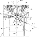
Im Folgenden wird die Erfindung anhand eines Ausführungsbeispiels gemäß
Der in
Jeder Zylinder
Jeder Zylinder
Die Einspritzdüse
Zudem ist jeder Zylinder
Die Einspritzvorrichtung
Die Einspritzstrahlen
Die mit den beiden Einspritzvorrichtungen
BezugszeichenlisteLIST OF REFERENCE NUMBERS
- 11
- Zylinder cylinder
- 22
- Brennraum combustion chamber
- 33
- Zylinderkopf cylinder head
- 44
- Zylinderrohr cylinder tube
- 55
- Kolben piston
- 5a5a
- Kolbenboden piston crown
- 5b 5b
- Kolbenlängsachse piston longitudinal axis
- 66
- Einspritzvorrichtung Injector
- 6a6a
- Einspritzdüse injection
- 6b6b
- Einspritzstrahlen, Kraftstoffstrahlen Injection jets, fuel jets
- 6c6c
- Längsachse der Einspritzvorrichtung, virtuelle Verlängerung der Längsachse Longitudinal axis of the injection device, virtual extension of the longitudinal axis
- 77
- Einlassöffnung inlet port
- 7a7a
- Ansaugleitung suction
- 7b7b
- Einlassventil intake valve
- 88th
- Auslassöffnung outlet
- 8a8a
- Abgasleitung exhaust pipe
- 8b8b
- Auslassventil outlet valve
- 99
- zusätzliche Einspritzvorrichtung additional injection device
- 9a9a
- Einspritzdüse injection
- 9b9b
- Einspritzstrahlen, Kraftstoffstrahlen Injection jets, fuel jets
- 9c9c
- Längsachse der Einspritzvorrichtung, virtuelle Verlängerung der Längsachse Longitudinal axis of the injection device, virtual extension of the longitudinal axis
- αα
- Winkel zwischen der virtuellen Verlängerung der Längsachse der Einspritzvorrichtung und der virtuellen Verlängerung der Längsachse der zusätzlichen Einspritzvorrichtung Angle between the virtual extension of the longitudinal axis of the injector and the virtual extension of the longitudinal axis of the additional injector
- m1,fuel m 1, fuel
- mittels der Einspritzvorrichtung eingebrachte Kraftstoffmenge introduced by the injector amount of fuel
- m2,fuel m 2, fuel
- mittels der zusätzlichen Einspritzvorrichtung eingebrachte Kraftstoffmenge introduced by the additional injector amount of fuel
- nmot n mot
- Drehzahl der Brennkraftmaschine Speed of the internal combustion engine
ZITATE ENTHALTEN IN DER BESCHREIBUNG QUOTES INCLUDE IN THE DESCRIPTION
Diese Liste der vom Anmelder aufgeführten Dokumente wurde automatisiert erzeugt und ist ausschließlich zur besseren Information des Lesers aufgenommen. Die Liste ist nicht Bestandteil der deutschen Patent- bzw. Gebrauchsmusteranmeldung. Das DPMA übernimmt keinerlei Haftung für etwaige Fehler oder Auslassungen.This list of the documents listed by the applicant has been generated automatically and is included solely for the better information of the reader. The list is not part of the German patent or utility model application. The DPMA assumes no liability for any errors or omissions.
Zitierte PatentliteraturCited patent literature
- US 5421301 [0026, 0027, 0028, 0033, 0039, 0070] US 5421301 [0026, 0027, 0028, 0033, 0039, 0070]
Claims (21)
Priority Applications (5)
| Application Number | Priority Date | Filing Date | Title |
|---|---|---|---|
| DE102016212951.1A DE102016212951A1 (en) | 2016-07-15 | 2016-07-15 | Direct-injection spark-ignition internal combustion engine with injection device arranged in the cylinder tube and method for operating such an internal combustion engine |
| DE202016104439.1U DE202016104439U1 (en) | 2016-07-15 | 2016-08-12 | Direct-injection spark-ignited internal combustion engine with injection device arranged in the cylinder tube |
| US15/649,169 US10774776B2 (en) | 2016-07-15 | 2017-07-13 | Direct-injection, applied-ignition internal combustion engine with injection device arranged in the cylinder liner, and method for operating an internal combustion engine of said type |
| CN201710576003.3A CN107620661B (en) | 2016-07-15 | 2017-07-14 | Internal combustion engine and method for operating an internal combustion engine of said type |
| US16/906,838 US11927148B2 (en) | 2016-07-15 | 2020-06-19 | Direct-injection, applied-ignition internal combustion engine with injection device arranged in the cylinder liner, and method for operating an internal combustion engine of said type |
Applications Claiming Priority (1)
| Application Number | Priority Date | Filing Date | Title |
|---|---|---|---|
| DE102016212951.1A DE102016212951A1 (en) | 2016-07-15 | 2016-07-15 | Direct-injection spark-ignition internal combustion engine with injection device arranged in the cylinder tube and method for operating such an internal combustion engine |
Publications (1)
| Publication Number | Publication Date |
|---|---|
| DE102016212951A1 true DE102016212951A1 (en) | 2018-02-01 |
Family
ID=60940900
Family Applications (1)
| Application Number | Title | Priority Date | Filing Date |
|---|---|---|---|
| DE102016212951.1A Ceased DE102016212951A1 (en) | 2016-07-15 | 2016-07-15 | Direct-injection spark-ignition internal combustion engine with injection device arranged in the cylinder tube and method for operating such an internal combustion engine |
Country Status (3)
| Country | Link |
|---|---|
| US (2) | US10774776B2 (en) |
| CN (1) | CN107620661B (en) |
| DE (1) | DE102016212951A1 (en) |
Families Citing this family (5)
| Publication number | Priority date | Publication date | Assignee | Title |
|---|---|---|---|---|
| DE102017107947A1 (en) * | 2017-04-12 | 2018-10-18 | Volkswagen Ag | Spray pattern of a multi-hole injection valve for injection pressures above 300 bar in gasoline engines with central injector position |
| JP2020016171A (en) * | 2018-07-24 | 2020-01-30 | 株式会社Ihi | Fuel injection device and engine system |
| CN112763224A (en) * | 2020-12-22 | 2021-05-07 | 中国北方发动机研究所(天津) | Floating cylinder sleeve testing device |
| WO2022256061A1 (en) * | 2021-06-04 | 2022-12-08 | Cummins Inc. | Fuel system |
| CN116378842B (en) * | 2023-06-07 | 2023-09-19 | 潍柴动力股份有限公司 | Fuel injection methods, devices, equipment and vehicles |
Citations (1)
| Publication number | Priority date | Publication date | Assignee | Title |
|---|---|---|---|---|
| US5421301A (en) | 1994-02-14 | 1995-06-06 | Feuling; James J. | Direct cylinder fuel injection system for internal combustion engines |
Family Cites Families (32)
| Publication number | Priority date | Publication date | Assignee | Title |
|---|---|---|---|---|
| US2058487A (en) * | 1931-01-26 | 1936-10-27 | Bendix Res Corp | Internal combustion engine |
| US2800118A (en) * | 1953-03-24 | 1957-07-23 | Daimler Benz Ag | Four-cycle internal combustion engine having fuel injection means |
| US3154059A (en) * | 1962-10-25 | 1964-10-27 | Southwest Res Inst | Stratified spark ignition internal combustion engine |
| JPS49127106A (en) * | 1973-04-09 | 1974-12-05 | ||
| IT1118641B (en) * | 1979-05-22 | 1986-03-03 | Fiat Ricerche | INTERNAL COMBUSTION ENGINE WITH COMMAND IGNITION AND PETROL INJECTION IN THE CYLINDER |
| US4543930A (en) * | 1983-11-17 | 1985-10-01 | Southwest Research Institute | Staged direct injection diesel engine |
| JPH07317632A (en) * | 1994-05-27 | 1995-12-05 | Mitsubishi Heavy Ind Ltd | Cylinder cover for diesel engine |
| US5735240A (en) * | 1995-06-19 | 1998-04-07 | Yamaha Hatsudoki Kabushiki Kaisha | Direct injected engine |
| US6148792A (en) * | 1997-02-01 | 2000-11-21 | Ford Global Technologies, Inc. | Direct injection spark ignition engine |
| JP3627546B2 (en) * | 1998-12-11 | 2005-03-09 | 日産自動車株式会社 | Direct cylinder injection spark ignition engine |
| DE19947150A1 (en) * | 1999-10-01 | 2001-04-05 | Volkswagen Ag | Spark ignition internal combustion engine and method for mixture formation in its combustion chamber |
| DE10124750A1 (en) * | 2001-05-21 | 2002-11-28 | Bosch Gmbh Robert | Fuel injection system has injection valve in combustion chamber near inlet valve and facing cylinder wall and produces several fuel jets, at least one oriented tangentially near ignition plug |
| JP2008095558A (en) * | 2006-10-06 | 2008-04-24 | Hitachi Ltd | Spark ignition type cylinder injection internal combustion engine |
| US7712451B2 (en) * | 2008-05-07 | 2010-05-11 | Visteon Global Technologies, Inc. | Multi-fuel multi-injection system for an internal combustion engine |
| JP2010001830A (en) * | 2008-06-20 | 2010-01-07 | Mazda Motor Corp | Cylinder direct injection type spark ignition internal combustion engine |
| JP5163530B2 (en) * | 2009-02-19 | 2013-03-13 | 日産自動車株式会社 | Compression ignition internal combustion engine |
| US8671908B2 (en) * | 2009-07-31 | 2014-03-18 | Ford Global Technologies, Llc | Glow plug placement in a diesel engine |
| US8100107B2 (en) | 2010-07-21 | 2012-01-24 | Ford Global Technologies, Llc | Method and system for engine control |
| US8171912B2 (en) * | 2011-04-20 | 2012-05-08 | Ford Global Technologies, Llc | Method and system for pre-ignition control |
| JP5549641B2 (en) * | 2011-05-23 | 2014-07-16 | 株式会社デンソー | Combustion system for internal combustion engine |
| DE102011086957A1 (en) * | 2011-11-23 | 2013-05-23 | Robert Bosch Gmbh | Method for controlling a solenoid valve, and computer program and control and / or regulating device |
| JP5564484B2 (en) * | 2011-11-25 | 2014-07-30 | 本田技研工業株式会社 | Internal combustion engine |
| DE102012011149A1 (en) * | 2012-06-05 | 2013-12-05 | Abb Turbo Systems Ag | Injection system for compression ignition diesel engines |
| US9500168B2 (en) | 2012-10-31 | 2016-11-22 | Electro-Motive Diesel, Inc. | Fuel system having a fuel-cooled injector |
| US9046068B2 (en) * | 2012-10-31 | 2015-06-02 | Electro-Motive Diesel, Inc. | Fuel system for a dual-fuel engine |
| CN104343605A (en) * | 2013-08-09 | 2015-02-11 | 天津滨海盛新达柴油技术服务有限公司 | Oil injection device of diesel engine |
| EP2860389B1 (en) * | 2013-10-14 | 2016-08-03 | Continental Automotive GmbH | Fuel injector assembly |
| WO2015078963A1 (en) * | 2013-11-29 | 2015-06-04 | Abb Turbo Systems Ag | Injection system for compression-ignited diesel engines |
| GB2528861B8 (en) * | 2014-07-31 | 2018-01-31 | Ricardo Uk Ltd | Liquid injection of normally gaseous fuel into an internal combustion engine |
| SG11201802914XA (en) * | 2015-10-28 | 2018-05-30 | Hans Jensen Lubricators As | A large slow-running two-stroke engine with sip lubricant injector |
| DE102016205875B4 (en) * | 2016-03-16 | 2020-12-10 | Ford Global Technologies, Llc | Direct injection spark-ignition internal combustion engine with an injection device arranged in the cylinder tube and a method for operating such an internal combustion engine |
| DE202016102651U1 (en) | 2016-03-16 | 2016-06-09 | Ford Global Technologies, Llc | Direct injection internal combustion engine with injection device arranged in the cylinder tube |
-
2016
- 2016-07-15 DE DE102016212951.1A patent/DE102016212951A1/en not_active Ceased
-
2017
- 2017-07-13 US US15/649,169 patent/US10774776B2/en not_active Expired - Fee Related
- 2017-07-14 CN CN201710576003.3A patent/CN107620661B/en not_active Expired - Fee Related
-
2020
- 2020-06-19 US US16/906,838 patent/US11927148B2/en active Active
Patent Citations (1)
| Publication number | Priority date | Publication date | Assignee | Title |
|---|---|---|---|---|
| US5421301A (en) | 1994-02-14 | 1995-06-06 | Feuling; James J. | Direct cylinder fuel injection system for internal combustion engines |
Also Published As
| Publication number | Publication date |
|---|---|
| US11927148B2 (en) | 2024-03-12 |
| US10774776B2 (en) | 2020-09-15 |
| CN107620661A (en) | 2018-01-23 |
| CN107620661B (en) | 2021-07-30 |
| US20200318573A1 (en) | 2020-10-08 |
| US20180017013A1 (en) | 2018-01-18 |
Similar Documents
| Publication | Publication Date | Title |
|---|---|---|
| DE69811558T2 (en) | Internal combustion engine with direct injection | |
| DE102010038082A1 (en) | Direct injection internal combustion engine with injector | |
| DE102018109939B4 (en) | Internal combustion engine | |
| DE102016212951A1 (en) | Direct-injection spark-ignition internal combustion engine with injection device arranged in the cylinder tube and method for operating such an internal combustion engine | |
| EP1319822A1 (en) | Combustion engine with direct injection | |
| DE19741380A1 (en) | Direct-injection piston engine with injector at inlet side | |
| WO2020259962A1 (en) | Hpdf operating method for an internal combustion engine, internal combustion engine and work device | |
| EP2003303B1 (en) | Piston with a piston bowl for a combustion engine and method for fuel-mixture generation using an injection device and such a piston | |
| EP0829636A1 (en) | Combustion chamber for internal combustion engines | |
| EP1272748A1 (en) | Internal combustion piston engine with direct fuel injection by means of an injector that is arranged on the input side | |
| DE10354827A1 (en) | fuel injection system | |
| DE102006037413B4 (en) | Direct-injection spark-ignition internal combustion engine and method for operating such an internal combustion engine | |
| DE202016104439U1 (en) | Direct-injection spark-ignited internal combustion engine with injection device arranged in the cylinder tube | |
| DE102016205875B4 (en) | Direct injection spark-ignition internal combustion engine with an injection device arranged in the cylinder tube and a method for operating such an internal combustion engine | |
| DE102011050087A1 (en) | Reciprocating internal combustion engine for vehicle, has fuel injection valve that is formed axially between top dead center and bottom dead center of piston | |
| DE202016102651U1 (en) | Direct injection internal combustion engine with injection device arranged in the cylinder tube | |
| DE69709806T2 (en) | Combustion chamber of a diesel engine | |
| DE102016212953A1 (en) | Direct injection internal combustion engine with injection device arranged in the cylinder tube and method for operating such an internal combustion engine | |
| DE102004002296B4 (en) | Fuel injection and method for injection of fuel | |
| DE102014218655B4 (en) | Method for operating a partially switched off self-igniting internal combustion engine and internal combustion engine for carrying out such a method | |
| DE102007042419A1 (en) | Gasoline engine for vehicle, has cylinder in which piston moves longitudinally, for implementing operating cycle comprising multiple stroke between lower and upper dead centers | |
| EP2003304B1 (en) | Piston with a piston bowl for a combustion engine and method for fuel-mixture generation using an injection device and such a piston | |
| EP1290320B1 (en) | Fuel injection system and method for the injection of fuel | |
| DE102016204297B4 (en) | Direct-injection spark-ignition internal combustion engine with injection device arranged in the cylinder tube and method for operating such an internal combustion engine | |
| DE102013221308A1 (en) | Method for mixture formation in a direct-injection spark-ignited internal combustion engine and internal combustion engine for carrying out such a method |
Legal Events
| Date | Code | Title | Description |
|---|---|---|---|
| R012 | Request for examination validly filed | ||
| R016 | Response to examination communication | ||
| R082 | Change of representative |
Representative=s name: PATERIS THEOBALD ELBEL FISCHER, PATENTANWAELTE, DE Representative=s name: PATERIS THEOBALD ELBEL & PARTNER, PATENTANWAEL, DE |
|
| R002 | Refusal decision in examination/registration proceedings | ||
| R003 | Refusal decision now final |