DE102016205120A1 - Absorption chiller - Google Patents
Absorption chiller Download PDFInfo
- Publication number
- DE102016205120A1 DE102016205120A1 DE102016205120.2A DE102016205120A DE102016205120A1 DE 102016205120 A1 DE102016205120 A1 DE 102016205120A1 DE 102016205120 A DE102016205120 A DE 102016205120A DE 102016205120 A1 DE102016205120 A1 DE 102016205120A1
- Authority
- DE
- Germany
- Prior art keywords
- absorbent
- membrane
- working medium
- heat
- path
- Prior art date
- Legal status (The legal status is an assumption and is not a legal conclusion. Google has not performed a legal analysis and makes no representation as to the accuracy of the status listed.)
- Withdrawn
Links
Images


Classifications
-
- F—MECHANICAL ENGINEERING; LIGHTING; HEATING; WEAPONS; BLASTING
- F25—REFRIGERATION OR COOLING; COMBINED HEATING AND REFRIGERATION SYSTEMS; HEAT PUMP SYSTEMS; MANUFACTURE OR STORAGE OF ICE; LIQUEFACTION SOLIDIFICATION OF GASES
- F25B—REFRIGERATION MACHINES, PLANTS OR SYSTEMS; COMBINED HEATING AND REFRIGERATION SYSTEMS; HEAT PUMP SYSTEMS
- F25B15/00—Sorption machines, plants or systems, operating continuously, e.g. absorption type
- F25B15/16—Sorption machines, plants or systems, operating continuously, e.g. absorption type using desorption cycle
-
- F—MECHANICAL ENGINEERING; LIGHTING; HEATING; WEAPONS; BLASTING
- F25—REFRIGERATION OR COOLING; COMBINED HEATING AND REFRIGERATION SYSTEMS; HEAT PUMP SYSTEMS; MANUFACTURE OR STORAGE OF ICE; LIQUEFACTION SOLIDIFICATION OF GASES
- F25B—REFRIGERATION MACHINES, PLANTS OR SYSTEMS; COMBINED HEATING AND REFRIGERATION SYSTEMS; HEAT PUMP SYSTEMS
- F25B15/00—Sorption machines, plants or systems, operating continuously, e.g. absorption type
- F25B15/02—Sorption machines, plants or systems, operating continuously, e.g. absorption type without inert gas
- F25B15/06—Sorption machines, plants or systems, operating continuously, e.g. absorption type without inert gas the refrigerant being water vapour evaporated from a salt solution, e.g. lithium bromide
-
- F—MECHANICAL ENGINEERING; LIGHTING; HEATING; WEAPONS; BLASTING
- F02—COMBUSTION ENGINES; HOT-GAS OR COMBUSTION-PRODUCT ENGINE PLANTS
- F02G—HOT GAS OR COMBUSTION-PRODUCT POSITIVE-DISPLACEMENT ENGINE PLANTS; USE OF WASTE HEAT OF COMBUSTION ENGINES; NOT OTHERWISE PROVIDED FOR
- F02G5/00—Profiting from waste heat of combustion engines, not otherwise provided for
- F02G5/02—Profiting from waste heat of exhaust gases
-
- F—MECHANICAL ENGINEERING; LIGHTING; HEATING; WEAPONS; BLASTING
- F25—REFRIGERATION OR COOLING; COMBINED HEATING AND REFRIGERATION SYSTEMS; HEAT PUMP SYSTEMS; MANUFACTURE OR STORAGE OF ICE; LIQUEFACTION SOLIDIFICATION OF GASES
- F25B—REFRIGERATION MACHINES, PLANTS OR SYSTEMS; COMBINED HEATING AND REFRIGERATION SYSTEMS; HEAT PUMP SYSTEMS
- F25B2315/00—Sorption refrigeration cycles or details thereof
- F25B2315/002—Generator absorber heat exchanger [GAX]
-
- F—MECHANICAL ENGINEERING; LIGHTING; HEATING; WEAPONS; BLASTING
- F25—REFRIGERATION OR COOLING; COMBINED HEATING AND REFRIGERATION SYSTEMS; HEAT PUMP SYSTEMS; MANUFACTURE OR STORAGE OF ICE; LIQUEFACTION SOLIDIFICATION OF GASES
- F25B—REFRIGERATION MACHINES, PLANTS OR SYSTEMS; COMBINED HEATING AND REFRIGERATION SYSTEMS; HEAT PUMP SYSTEMS
- F25B2500/00—Problems to be solved
- F25B2500/01—Geometry problems, e.g. for reducing size
-
- Y—GENERAL TAGGING OF NEW TECHNOLOGICAL DEVELOPMENTS; GENERAL TAGGING OF CROSS-SECTIONAL TECHNOLOGIES SPANNING OVER SEVERAL SECTIONS OF THE IPC; TECHNICAL SUBJECTS COVERED BY FORMER USPC CROSS-REFERENCE ART COLLECTIONS [XRACs] AND DIGESTS
- Y02—TECHNOLOGIES OR APPLICATIONS FOR MITIGATION OR ADAPTATION AGAINST CLIMATE CHANGE
- Y02B—CLIMATE CHANGE MITIGATION TECHNOLOGIES RELATED TO BUILDINGS, e.g. HOUSING, HOUSE APPLIANCES OR RELATED END-USER APPLICATIONS
- Y02B30/00—Energy efficient heating, ventilation or air conditioning [HVAC]
- Y02B30/62—Absorption based systems
- Y02B30/625—Absorption based systems combined with heat or power generation [CHP], e.g. trigeneration
-
- Y—GENERAL TAGGING OF NEW TECHNOLOGICAL DEVELOPMENTS; GENERAL TAGGING OF CROSS-SECTIONAL TECHNOLOGIES SPANNING OVER SEVERAL SECTIONS OF THE IPC; TECHNICAL SUBJECTS COVERED BY FORMER USPC CROSS-REFERENCE ART COLLECTIONS [XRACs] AND DIGESTS
- Y02—TECHNOLOGIES OR APPLICATIONS FOR MITIGATION OR ADAPTATION AGAINST CLIMATE CHANGE
- Y02T—CLIMATE CHANGE MITIGATION TECHNOLOGIES RELATED TO TRANSPORTATION
- Y02T10/00—Road transport of goods or passengers
- Y02T10/10—Internal combustion engine [ICE] based vehicles
- Y02T10/12—Improving ICE efficiencies
Landscapes
- Engineering & Computer Science (AREA)
- Mechanical Engineering (AREA)
- General Engineering & Computer Science (AREA)
- Chemical & Material Sciences (AREA)
- Physics & Mathematics (AREA)
- Thermal Sciences (AREA)
- Combustion & Propulsion (AREA)
- Materials Engineering (AREA)
- Sorption Type Refrigeration Machines (AREA)
Abstract
Die vorliegende Erfindung betrifft eine Absorptionskältemaschine (1), insbesondere zur Abwärmerückgewinnung bei einer Brennkraftmaschine, die einen Absorptionsmittelkreis (2), in dem ein Absorptionsmittel zirkuliert und der einen Absorber (3) sowie einen Desorber (4) aufweist, und einen Arbeitsmittelkreis (9) aufweist, in dem ein Arbeitsmittel zirkuliert und der einen Verdampfer (10) sowie einen Kondensator (11) aufweist.
Eine kompakte Bauweise ergibt sich mit einer Niederdruck-Membrananordnung (21), die für Arbeitsmitteldampf durchlässig ist und für flüssiges Arbeitsmittel sowie für flüssiges Absorptionsmittel undurchlässig ist und die zwischen dem Verdampfer (10) und dem Absorber (3) so angeordnet ist, dass sie einerseits mit dem Arbeitsmittel und andererseits mit dem Absorptionsmittel in Kontakt steht, und mit einer Hochdruck-Membrananordnung (23), die für Arbeitsmitteldampf durchlässig ist und für flüssiges Arbeitsmittel sowie für flüssiges Absorptionsmittel undurchlässig ist und die zwischen dem Desorber (4) und dem Kondensator (11) so angeordnet ist, dass sie einerseits mit dem Arbeitsmittel und andererseits mit dem Absorptionsmittel in Kontakt steht.The present invention relates to an absorption refrigerating machine (1), in particular for waste heat recovery in an internal combustion engine, which comprises an absorption medium circuit (2) in which an absorbent circulates and which has an absorber (3) and a desorber (4), and a working medium circuit (9). in which circulates a working fluid and having an evaporator (10) and a capacitor (11).
A compact construction results with a low-pressure membrane assembly (21), which is permeable to working medium vapor and impermeable to liquid working fluid and liquid absorbent and which is arranged between the evaporator (10) and the absorber (3) so that they on the one hand with the working fluid and on the other hand with the absorbent in contact, and with a high-pressure membrane assembly (23) which is permeable to working medium vapor and impermeable to liquid working fluid and liquid absorbent and between the desorber (4) and the capacitor (11 ) is arranged so that it is on the one hand in contact with the working fluid and on the other hand with the absorbent.
Description
Die vorliegende Erfindung betrifft eine Absorptionskältemaschine, die insbesondere zur Abwärmerückgewinnung bei einer Brennkraftmaschine, vorzugsweise in einem Kraftfahrzeug, geeignet ist. Die Erfindung betrifft außerdem ein Verfahren zum Betreiben einer derartigen Absorptionskältemaschine.The present invention relates to an absorption refrigeration machine, which is particularly suitable for waste heat recovery in an internal combustion engine, preferably in a motor vehicle. The invention also relates to a method of operating such an absorption chiller.
Aus der
Die vorliegende Erfindung beschäftigt sich mit dem Problem, für eine Absorptionskältemaschine eine verbesserte oder zumindest eine andere Ausführungsform anzugeben, die sich insbesondere durch einen kompakten Aufbau auszeichnet. The present invention is concerned with the problem of providing for an absorption refrigeration machine an improved or at least another embodiment, which is characterized in particular by a compact structure.
Dieses Problem wird erfindungsgemäß durch den Gegenstand des unabhängigen Anspruchs gelöst. Vorteilhafte Ausführungsformen sind Gegenstand der abhängigen Ansprüche.This problem is solved according to the invention by the subject matter of the independent claim. Advantageous embodiments are the subject of the dependent claims.
Die erfindungsgemäße Absorptionskältemaschine umfasst einen Absorptionsmittelkreis, in dem ein Absorptionsmittel zirkuliert und der einen Absorber sowie einen Desorber aufweist, sowie einen Arbeitsmittelkreis, in dem ein Arbeitsmittel zirkuliert und der einen Verdampfer sowie einen Kondensator aufweist. Es sind somit zwei separate Kreise vorgesehen, um einerseits das Absorptionsmittel und andererseits das Arbeitsmittel zu führen. Diese beiden an sich separaten Kreise sind mit Hilfe von zwei Membrananordnungen miteinander gekoppelt, nämlich über eine Niederdruck-Membrananordnung, die im Folgenden als ND-Membrananordnung bezeichnet wird, und über eine Hochdruck-Membrananordnung, die im Folgenden auch als HD-Membrananordnung bezeichnet wird. Die ND-Membrananordnung ist für dampfförmiges Arbeitsmittel durchlässig, während sie für flüssiges Arbeitsmittel sowie für flüssiges Absorptionsmittel undurchlässig ist. Somit kann über die ND-Membrananordnung dampfförmiges Arbeitsmittel vom Arbeitsmittelkreis in den Absorptionsmittelkreis übertreten. Ferner ist die ND-Membrananordnung zwischen dem Verdampfer und dem Absorber so angeordnet, dass sie einerseits dem Arbeitsmittel und andererseits dem Absorptionsmittel direkt ausgesetzt ist, also während des Betriebs der Absorptionskältemaschine damit in Kontakt steht. Somit kann Arbeitmitteldampf unmittelbar vom Arbeitsmittel durch die ND-Membrananordnung hindurch in das Absorptionsmittel gelangen. Die HD-Membrananordnung ist ebenfalls für dampfförmiges Arbeitsmittel durchlässig, während sie für flüssiges Arbeitsmittel sowie für flüssiges Absorptionsmittel undurchlässig ist. Grundsätzlich können ND-Membrananordnung und HD-Membrananordnung identisch aufgebaut sein. Die HD-Membrananordnung ist zwischen dem Desorber und dem Kondensator so angeordnet, dass sie einerseits dem Arbeitsmittel und andererseits dem Absorptionsmittel direkt ausgesetzt ist, also während des Betriebs der Absorptionskältemaschine damit in Kontakt steht. Somit kann dampfförmiges Arbeitsmittel vom Absorptionsmittelkreis unmittelbar durch die HD-Membrananordnung in den Arbeitsmittelkreis gelangen. Durch diese Maßnahmen baut die hier vorgestellte Absorptionskältemaschine einerseits im Bereich des Absorbers und des Verdampfers und andererseits im Bereich des Desorbers und des Kondensators extrem kompakt, so dass die Absorptionskältemaschine wenig Bauraum benötigt. The absorption refrigerating machine according to the invention comprises an absorption medium circuit in which an absorbent circulates and which has an absorber and a desorber, and a working medium circuit in which a working medium circulates and which has an evaporator and a condenser. Thus, two separate circuits are provided to guide on the one hand the absorbent and on the other hand the working fluid. These two separate circuits are coupled to one another with the aid of two membrane arrangements, namely via a low-pressure membrane arrangement, which is referred to below as ND membrane arrangement, and via a high-pressure membrane arrangement, which is also referred to below as HD membrane arrangement. The LP membrane assembly is permeable to vaporous working fluid while being impermeable to liquid working fluid as well as liquid absorbent. Thus, vaporous working fluid can pass from the working fluid circuit into the absorption medium circuit via the LP diaphragm arrangement. Further, the ND membrane assembly between the evaporator and the absorber is arranged so that it is directly exposed on the one hand to the working fluid and on the other hand the absorbent, so it is in contact during operation of the absorption chiller. Thus, working fluid vapor can pass directly from the working fluid through the ND membrane assembly into the absorbent. The HD membrane assembly is also permeable to vaporous working fluid while being impermeable to liquid working fluid as well as to liquid absorbent. In principle, ND membrane arrangement and HD membrane arrangement can be constructed identically. The HD membrane assembly is disposed between the desorber and the condenser so that it is directly exposed to the working fluid and the absorbent on the one hand, so that it is in contact with it during operation of the absorption chiller. Thus, vaporous working fluid can pass from the absorbent loop directly through the HD membrane assembly into the working fluid circuit. By means of these measures, the absorption chiller presented here, on the one hand, builds extremely compact in the area of the absorber and the evaporator and, on the other hand, in the area of the desorber and the condenser, so that the absorption chiller requires little installation space.
Besonders vorteilhaft ist nun eine Ausführungsform, bei der zumindest eine dieser Membrananordnungen eine Arbeitsmittelmembran und zusätzlich eine Absorptionsmittelmembran aufweist. Die Arbeitsmittelmembran ist direkt dem Arbeitsmittel ausgesetzt und steht während des Betriebs der Absorptionskältemaschine damit in Kontakt. Die Arbeitsmittelmembran ist für Arbeitsmitteldampf durchlässig, während sie für flüssiges Arbeitsmittel undurchlässig ist. Die Absorptionsmittelmembran ist direkt dem Absorptionsmittel ausgesetzt und steht während des Betriebs der Absorptionskältemaschine mit dem Absorptionsmittel in Kontakt. Die Absorptionsmittelmembran ist für Arbeitsmitteldampf durchlässig, während sie für flüssiges Absorptionsmittel undurchlässig ist. Durch diese beiden separaten Membranen innerhalb der jeweiligen Membrananordnung lassen sich Absorber und Verdampfer einerseits, wenn es sich um die ND-Membrananordnung handelt, bzw. Desorber und Kondensator andererseits, wenn es sich um die HD-Membrananordnung handelt, besser thermisch voneinander trennen, wodurch parasitäre Wärmeströme, welche die Effizienz der Absorptionskältemaschine reduzieren, verringert werden können. Dementsprechend kann die jeweilige Membrananordnung mit zumindest zwei Membranen die Effizienz der Absorptionskältemaschine verbessern. Vorzugsweise besitzt die jeweilige Membrananordnung genau zwei getrennte Membranen, nämlich die Arbeitsmittelmembran und die Absorptionsmittelmembran. In diesem Fall ist die jeweilige Membrananordnung dann als Doppelmembran ausgestaltet. Bevorzugt ist dabei eine Ausführungsform, bei der sowohl die ND-Membrananordnung als auch die HD-Membrananordnung jeweils mit einer solchen Arbeitsmittelmembran und einer solchen Absorptionsmittelmembran ausgestattet sind. Arbeitsmittelmembran und Absorptionsmittelmembran können grundsätzlich aus identischem Membranmaterial bestehen. Zweckmäßig können sie jedoch aus verschiedenen Membranmaterialien bestehen, die beispielsweise für den jeweiligen Druckbereich, nämlich ND bzw. HD, angepasst sind. An embodiment in which at least one of these membrane arrangements has a working medium membrane and, in addition, an absorbent membrane is particularly advantageous. The working medium membrane is directly exposed to the working fluid and is in contact with it during operation of the absorption refrigerating machine. The working fluid membrane is permeable to working medium vapor while being impermeable to liquid working fluid. The absorbent membrane is exposed directly to the absorbent and is in contact with the absorbent during operation of the absorption chiller. The absorbent membrane is permeable to working medium vapor while being impermeable to liquid absorbent. Through these two separate membranes within the respective membrane arrangement absorber and evaporator on the one hand, when it comes to the LP membrane assembly and desorber and condenser on the other hand, when it comes to the HD membrane assembly, better thermally separate from each other, causing parasitic Heat flows, which reduce the efficiency of the absorption chiller, can be reduced. Accordingly, the respective membrane arrangement with at least two membranes can improve the efficiency of the absorption refrigeration machine. Preferably, the respective membrane arrangement has exactly two separate membranes, namely the working medium membrane and the absorbent membrane. In this case, the respective membrane arrangement is then designed as a double membrane. An embodiment in which both the LP membrane arrangement and the HD membrane arrangement are each provided with such a working medium membrane and one such membrane is preferred Absorbent membrane are equipped. Working medium membrane and absorbent membrane can basically consist of identical membrane material. However, they may suitably consist of different membrane materials, which are adapted, for example, for the respective pressure range, namely ND or HD.
Gemäß einer vorteilhaften Weiterbildung kann in der jeweiligen Membrananordnung zwischen der Arbeitsmittelmembran und der Absorptionsmittelmembran ein Zwischenraum ausgebildet sein. Mit Hilfe eines derartigen Zwischenraums können unerwünschte Wärmeströme weiter reduziert werden.According to an advantageous development, a gap can be formed in the respective membrane arrangement between the working medium membrane and the absorbent membrane. With the help of such a gap unwanted heat flows can be further reduced.
Besonders vorteilhaft ist eine Weiterbildung, bei der im Zwischenraum ein Tiefdruck herrscht, der unterhalb des Niederdrucks liegt und der insbesondere unterhalb eines atmosphärischen Umgebungsdrucks liegt, der üblicherweise etwa 1 bar beträgt. Durch einen Unterdruck im Zwischenraum wird einerseits die thermische Isolationswirkung verbessert. Andererseits wird dadurch die Partialdruckdifferenz an der jeweiligen Membran für den Arbeitsmitteldampf vergrößert, was die Durchlässigkeit der jeweiligen Membran für Arbeitsmitteldampf erhöht. Außerdem steigt dadurch der Partialdruckanteil des Arbeitsmitteldampfs im Zwischenraum, was ebenfalls für die Effizienz der Absorptionskältemaschine von Vorteil ist. Insbesondere lässt sich der Volumenstrom des Arbeitsmitteldampfs vergrößern.Particularly advantageous is a development in which there is a gravure in the intermediate space, which is below the low pressure and which is in particular below an atmospheric ambient pressure, which is usually about 1 bar. By a negative pressure in the space on the one hand, the thermal insulation effect is improved. On the other hand, this increases the partial pressure difference at the respective membrane for the working medium vapor, which increases the permeability of the respective membrane for working medium vapor. In addition, this increases the partial pressure of the working medium vapor in the intermediate space, which is also beneficial for the efficiency of the absorption chiller. In particular, the volume flow of the working medium vapor can be increased.
Die Verwendung von zwei separaten Membranen mit oder ohne Zwischenraum ermöglicht es außerdem, sowohl den Absorptionsmittelkreis als auch den Arbeitskreis mit einem Überdruck zu betreiben, also mit einem Druck, der oberhalb des Umgebungsdrucks liegt. Mit anderen Worten, sowohl der HD im Bereich von Kondensator und Absorber als auch der ND im Bereich von Desorber und Kondensator liegen oberhalb des Umgebungsdrucks. Hierdurch wird die Gefahr, dass Fremdgase in das Arbeitsmittel bzw. in das Absorptionsmittel eindringen, reduziert.The use of two separate diaphragms with or without a gap also makes it possible to operate both the absorption medium circuit and the working group with an overpressure, that is to say with a pressure which is above the ambient pressure. In other words, both the HD in the range of the condenser and the absorber and the ND in the range of the desorber and the condenser are above the ambient pressure. This reduces the risk of foreign gases entering the working medium or the absorbent.
Vorteilhaft ist eine Weiterbildung, bei der innerhalb der jeweiligen Membrananordnung eine Spacerschicht vorgesehen ist, die zwischen der jeweiligen Arbeitsmittelmembran und der jeweiligen Absorptionsmittelmembran angeordnet ist, um dort den genannten Zwischenraum zu bilden. Die Spacerschicht ist dabei für Arbeitsmitteldampf durchlässig. Sie ist beispielsweise durch eine Gitterstruktur oder Gewebestruktur gebildet und somit üblicherweise auch für das flüssige Arbeitsmittel sowie für das flüssige Absorptionsmittel durchlässig. An der Spacerschicht können einerseits die Arbeitsmittelmembran und andererseits die Absorptionsmittelmembran unmittelbar anliegen. Die Spacerschicht kann dabei insbesondere zu einer Versteifung bzw. Stabilisierung der jeweiligen Membrananordnung führen, da die hierbei zur Verwendung kommenden Membranen üblicherweise relativ biegeweich sind. A further development is advantageous, in which a spacer layer is provided within the respective membrane arrangement, which is arranged between the respective working medium membrane and the respective absorbent membrane, in order to form the said intermediate space there. The spacer layer is permeable to working medium vapor. It is formed for example by a grid structure or fabric structure and thus usually also permeable to the liquid working medium and for the liquid absorbent. On the spacer layer, on the one hand, the working medium membrane and, on the other hand, the absorbent membrane can abut directly. The spacer layer may in particular lead to a stiffening or stabilization of the respective membrane arrangement, since the membranes used for this purpose are usually relatively flexible.
Gemäß einer vorteilhaften Ausführungsform kann die Absorptionskältemaschine mit einer Verdampfer-Absorber-Einheit ausgestattet sein. Hierdurch wird für den Verdampfer und den Absorber eine besonders kompakte Baugruppe bereitgestellt. Zweckmäßig sind in der Verdampfer-Absorber-Einheit ein Absorptionsmittelpfad zum Führen des Absorptionsmittels und ein Arbeitsmittelpfad zum Führen des Arbeitsmittels durch die ND-Membrananordnung voneinander getrennt. According to an advantageous embodiment, the absorption chiller may be equipped with an evaporator-absorber unit. As a result, a particularly compact assembly is provided for the evaporator and the absorber. Suitably, in the evaporator-absorber unit, an absorbent path for guiding the absorbent and a working fluid path for guiding the working fluid through the LP membrane assembly are separated from each other.
Vorteilhaft ist eine Weiterbildung, bei der eine Niederdruck-Wärmeabführung (ND-Wärmeabführung) zum Abführen von Wärme vom Absorber einen Niederdruck-Kühlmittelpfad (ND-Kühlmittelpfad) zum Führen eines Kühlmittels aufweist, der in der Verdampfer-Absorber-Einheit mit dem Absorptionsmittelpfad wärmeübertragend und mediengetrennt gekoppelt ist. Auf diese Weise ist die ND-Wärmeabführung hinsichtlich ihrer Kühlfunktion in die Verdampfer-Absorber-Einheit integriert.Advantageously, a development in which a low-pressure heat dissipation (ND heat removal) for removing heat from the absorber has a low-pressure coolant path (ND coolant path) for guiding a coolant, which in the evaporator-absorber unit with the absorbent path and heat transfer is coupled media-separated. In this way, the ND heat removal is integrated with regard to their cooling function in the evaporator-absorber unit.
Bei einer anderen Weiterbildung kann zusätzlich oder alternativ eine Niederdruck-Wärmezuführung (ND-Wärmezuführung) zum Zuführen von Wärme zum Verdampfer einen Niederdruck-Heizmittelpfad (ND-Heizmittelpfad) zum Führen eines Heizmittels aufweisen, der in der Verdampfer-Absorber-Einheit mit dem Arbeitsmittelpfad wärmeübertragend und mediengetrennt gekoppelt ist. Auf diese Weise kann die ND-Wärmezuführung hinsichtlich ihrer Heizfunktion in die Verdampfer-Absorber-Einheit integriert werden. In another development, additionally or alternatively, a low-pressure heat supply (ND heat supply) for supplying heat to the evaporator, a low-pressure Heizmittelpfad (ND Heizmittelpfad) for guiding a heating means, the heat transfer in the evaporator-absorber unit with the working medium path and media-separated coupled. In this way, the ND heat supply can be integrated in terms of their heating function in the evaporator-absorber unit.
Besonders vorteilhaft ist eine derartige Verdampfer-Absorber-Einheit dann vorgesehen, wenn die ND-Membrananordnung mit einer solchen Arbeitsmittelmembran und einer solchen Absorptionsmittelmembran ausgestattet ist. Such an evaporator-absorber unit is particularly advantageously provided when the LP-membrane assembly is equipped with such a working medium membrane and such an absorbent membrane.
Bei einer anderen Ausführungsform kann die Absorptionskältemaschine mit einer Kondensator-Desorber-Einheit ausgestattet sein, wodurch Kondensator und Desorber eine kompakte Einheit bilden. Zweckmäßig kann nun in der Kondensator-Desorber-Einheit ein Absorptionsmittelpfad Führen des Absorptionsmittels durch die HD-Membrananordnung von einem Arbeitsmittelpfad zum Führen des Arbeitsmittels getrennt sein.In another embodiment, the absorption chiller may be equipped with a condenser-desorber unit whereby the condenser and desorber form a compact unit. Conveniently, in the condenser-desorber unit, an absorbent path leading the absorbent through the HD membrane assembly may now be separated from a working fluid path for guiding the working fluid.
Gemäß einer vorteilhaften Weiterbildung kann eine Hochdruck-Wärmeabführung (HD-Wärmeabführung) zum Abführen von Wärme vom Kondensator vorgesehen sein, die einen Hochdruck-Kühlmittelpfad (HD-Kühlmittelpfad) zum Führen eines Kühlmittels aufweist, der in der Kondensator-Desorber-Einheit mit dem Arbeitsmediumpfad wärmeübertragend und mediengetrennt gekoppelt ist. Auf diese Weise lässt sich die Kühlfunktion der HD-Wärmeabführung in die Kondensator-Desorber-Einheit integrieren.According to an advantageous development, high-pressure heat removal (HD heat removal) for removing heat from the condenser may be provided, which has a high-pressure coolant path (HD coolant path) for guiding a coolant which is present in the condenser desorber. Unit with the working medium path is heat-transmitting and media-separated coupled. In this way, the cooling function of the HD heat dissipation can be integrated into the condenser-desorber unit.
Zusätzlich oder alternativ kann eine Hochdruck-Wärmezuführung (HD-Wärmezuführung) zum Zuführen von Wärme zum Desorber vorgesehen sein, die einen Hochdruck-Heizmittelpfad (HD-Heizmittelpfad) zum Führen eines Heizmittels aufweist, der in der Kondensator-Desorber-Einheit mit dem Arbeitmittelpfad wärmeübertragend und mediengetrennt gekoppelt ist. Auf diese Weise lässt sich die Heizfunktion der HD-Wärmezuführung in die Kondensator-Desorber-Einheit integrieren.Additionally or alternatively, a high-pressure heat supply (HD heat supply) for supplying heat to the desorber may be provided which has a high-pressure Heizmittelpfad (HD Heizmittelpfad) for guiding a heating medium, which in the condenser-desorber unit with the working medium path heat transfer and media-separated coupled. In this way, the heating function of the HD heat supply can be integrated into the condenser-desorber unit.
Besonders zweckmäßig ist eine solche Kondensator-Desorber-Einheit dann, wenn die HD-Membrananordnung mit einer solchen Arbeitsmittelmembran und mit einer solchen Absorptionsmittelmembran ausgestattet ist. Such a condenser-desorber unit is particularly useful if the HD membrane arrangement is equipped with such a working medium membrane and with such an absorbent membrane.
Innerhalb der jeweiligen Einheit kann die wärmeübertragende und mediengetrennte Kopplung mittels einer Wärmeübertragerstruktur erfolgen, die für die jeweiligen Medien undurchlässig ist. Beispielsweise kann es sich dabei um eine unstrukturierte oder um eine strukturierte Platte oder Folie handeln, beispielsweise aus einem Metall. Beispielsweise kann hierbei eine Stahlplatte oder Stahlfolie, vorzugsweise eine Edelstahlplatte oder Edelstahlfolie, zum Einsatz kommen. Within the respective unit, the heat-transferring and media-separated coupling can be effected by means of a heat transfer structure, which is impermeable to the respective media. For example, it can be an unstructured or a structured plate or foil, for example a metal. For example, here a steel plate or steel foil, preferably a stainless steel plate or stainless steel foil, are used.
Bei einer anderen vorteilhaften Ausführungsform kann im Absorptionsmittelkreis ein Rekuperator angeordnet sein, der einen vom Absorber zum Desorber führenden Vorlauf des Absorptionsmittelkreises mit einem vom Desorber zum Absorber führenden Rücklauf des Absorptionsmittelkreises wärmeübertragend und mediengetrennt koppelt. Hierdurch kann der energetische Wirkungsgrad der Absorptionskältemaschine signifikant erhöht werden.In another advantageous embodiment, a recuperator may be arranged in the absorption medium circuit, which couples a leading from the absorber to the desorber flow of the absorbent circuit with a leading from the desorber to the absorber return of the absorption medium heat transfer and media separated. As a result, the energy efficiency of the absorption chiller can be significantly increased.
Die einzelnen Membranen, die in der jeweiligen Membrananordnung zur Anwendung kommen, können dabei als Hohlfasermembranen ausgestaltet sein. Bevorzugt ist jedoch eine Ausführungsform, bei der die Membranen als Flachmembranen ausgestaltet sind. The individual membranes that are used in the respective membrane arrangement can be designed as hollow-fiber membranes. However, an embodiment in which the membranes are configured as flat membranes is preferred.
Ein erfindungsgemäßes Verfahren zum Betreiben einer Absorptionskältemaschine der vorstehend beschriebenen Art zeichnet sich dadurch aus, dass der Hochdruck (HD) oberhalb des Niederdrucks (ND) liegt und dass der Hochdruck sowie der Niederdruck im Absorptionsmittelkreis innerhalb des flüssigen Absorptionsmittels und im Arbeitsmittelkreis innerhalb des flüssigen Arbeitsmittels oberhalb eines atmosphärischen Umgebungsdrucks liegt, der in der Regel etwa 1 bar beträgt. In einem Zwischenraum, der sich innerhalb der jeweiligen Membrananordnung zwischen der Arbeitsmittelmembran und der Absorptionsmittelmembran befindet, stellt sich dagegen ein Tiefdruck (TD) ein, der bevorzugt unterhalb des Umgebungsdrucks liegt. Mit anderen Worten, der Absorptionsmittelkreis und der Arbeitsmittelkreis werden in der Flüssigphase jeweils mit einem Überdruck betrieben, während innerhalb der jeweiligen Membrananordnung im genannten Zwischenraum ein Unterdruck eingestellt wird. Durch diese Betriebsweise wird einerseits erreicht, dass die Gefahr eines Eindringens von Fremdgasen aus der Umgebung in das Arbeitsmittel bzw. in das Absorptionsmittel reduziert ist, während andererseits der Volumenstrom an Arbeitsmitteldampf vergrößert werden kann. Gleichzeitig wird innerhalb der Membrananordnung ein parasitärer Wärmeübergang reduziert. Insgesamt lässt sich somit die Effizienz der Absorptionskältemaschine verbessern. Zum Einstellen des besagten Tiefdrucks kann im jeweiligen Zwischenraum zunächst eine vorausgehende Evakuierung im Rahmen der Herstellung der jeweiligen Membrananordnung durchgeführt werden, z.B. um störende Fremdgase zu entfernen. Anschließend stellt sich der jeweilige Tiefdruck dann während des Betriebs von selbst ein, nämlich durch den Dampfdruck des Arbeitsmitteldampfs. Bei einer Lithiumbromid-Wasserlösung kann dieser Tiefdruck im Zwischenraum der ND-Membrananordnung bei etwa 10 mbar liegen, während er im Zwischenraum der HD-Membrananordnung bei etwa 100 mbar liegen kann. An inventive method for operating an absorption chiller of the type described above is characterized in that the high pressure (HD) is above the low pressure (ND) and that the high pressure and the low pressure in the absorbent circuit within the liquid absorbent and in the working medium circle within the liquid working medium above an atmospheric ambient pressure is, which is usually about 1 bar. In contrast, in a gap which is located within the respective membrane arrangement between the working medium membrane and the absorbent membrane, a gravure pressure (TD) sets in, which is preferably below the ambient pressure. In other words, the absorption medium circuit and the working medium circuit are each operated with an overpressure in the liquid phase, while a negative pressure is set within the respective membrane arrangement in said intermediate space. This mode of operation on the one hand ensures that the risk of intrusion of foreign gases from the environment into the working medium or into the absorption medium is reduced, while on the other hand the volume flow of working medium vapor can be increased. At the same time a parasitic heat transfer is reduced within the membrane assembly. Overall, thus, the efficiency of the absorption refrigeration machine can be improved. To set said low pressure, a preliminary evacuation may be carried out in the respective intermediate space during the production of the respective membrane arrangement, e.g. to remove interfering foreign gases. Subsequently, the respective gravure then sets itself during operation, namely by the vapor pressure of the working medium vapor. In the case of a lithium bromide-water solution, this intraday pressure in the interspace of the LP membrane arrangement can be about 10 mbar, while it can be about 100 mbar in the interspace of the HD membrane arrangement.
Im vorliegenden Zusammenhang steht "ND" stets für "Niederdruck", während "HD" stets für Hochdruck steht, wobei die Begriffe relativ zu verstehen sind, so dass der HD oberhalb des ND liegt.As used herein, "ND" is always "low pressure", while "HD" is always high pressure, and the terms are to be understood relative to the HD being above the ND.
Weitere wichtige Merkmale und Vorteile der Erfindung ergeben sich aus den Unteransprüchen, aus den Zeichnungen und aus der zugehörigen Figurenbeschreibung anhand der Zeichnungen.Other important features and advantages of the invention will become apparent from the dependent claims, from the drawings and from the associated figure description with reference to the drawings.
Es versteht sich, dass die vorstehend genannten und die nachstehend noch zu erläuternden Merkmale nicht nur in der jeweils angegebenen Kombination, sondern auch in anderen Kombinationen oder in Alleinstellung verwendbar sind, ohne den Rahmen der vorliegenden Erfindung zu verlassen.It is understood that the features mentioned above and those yet to be explained below can be used not only in the particular combination given, but also in other combinations or in isolation, without departing from the scope of the present invention.
Bevorzugte Ausführungsbeispiele der Erfindung sind in den Zeichnungen dargestellt und werden in der nachfolgenden Beschreibung näher erläutert, wobei sich gleiche Bezugszeichen auf gleiche oder ähnliche oder funktional gleiche Komponenten beziehen.Preferred embodiments of the invention are illustrated in the drawings and will be described in more detail in the following description, wherein like reference numerals refer to the same or similar or functionally identical components.
Es zeigen, jeweils schematisch,Show, in each case schematically,
Entsprechend
Zur verbesserten energetischen Effizienz ist hier im Absorptionsmittelkreis
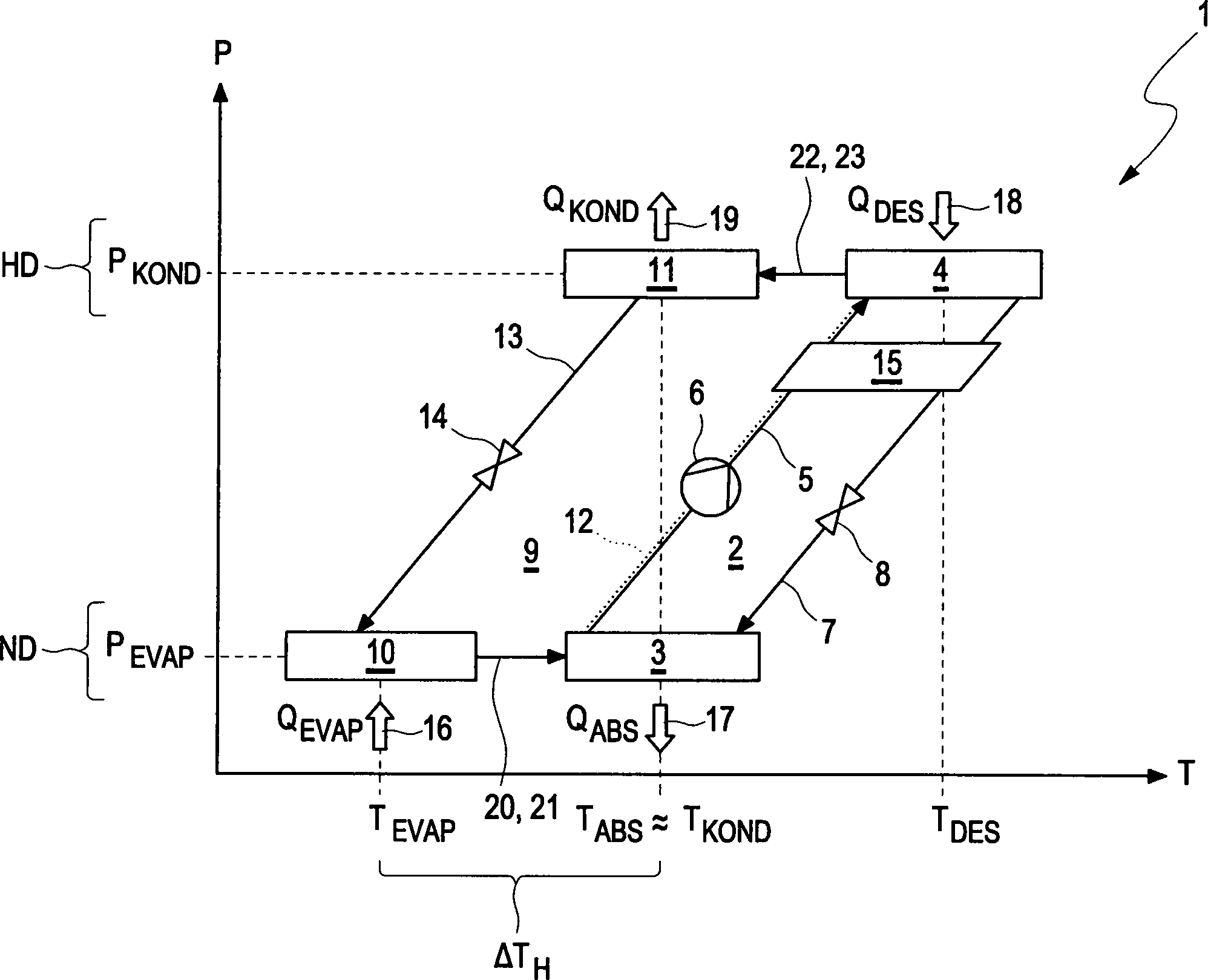
Wie sich dem Diagramm der
Gemäß
Der Kreisprozess der Absorptionskältemaschine
Im Desorber
Somit ist auch der Absorptionsmittelkreis
Meistens liegen die Temperaturen des Kondensators
Wie sich
Die Überführung des verdampften Arbeitsmittels in das Absorptionsmittel ist in
Entsprechend
Entsprechend den
Bei den hier gezeigten Ausführungsformen ist in der jeweiligen Membrananordnung
In
Die in
Gemäß den
Gemäß
Während des Betriebs der Absorptionskältemaschine
Vorzugsweise sind die hier zum Einsatz kommenden Membranen
Gemäß
ZITATE ENTHALTEN IN DER BESCHREIBUNG QUOTES INCLUDE IN THE DESCRIPTION
Diese Liste der vom Anmelder aufgeführten Dokumente wurde automatisiert erzeugt und ist ausschließlich zur besseren Information des Lesers aufgenommen. Die Liste ist nicht Bestandteil der deutschen Patent- bzw. Gebrauchsmusteranmeldung. Das DPMA übernimmt keinerlei Haftung für etwaige Fehler oder Auslassungen.This list of the documents listed by the applicant has been generated automatically and is included solely for the better information of the reader. The list is not part of the German patent or utility model application. The DPMA assumes no liability for any errors or omissions.
Zitierte PatentliteraturCited patent literature
- DE 102010049916 A1 [0002] DE 102010049916 A1 [0002]
Claims (15)
Priority Applications (2)
| Application Number | Priority Date | Filing Date | Title |
|---|---|---|---|
| DE102016205120.2A DE102016205120A1 (en) | 2016-03-29 | 2016-03-29 | Absorption chiller |
| US15/471,888 US20170284707A1 (en) | 2016-03-29 | 2017-03-28 | Absorption chiller |
Applications Claiming Priority (1)
| Application Number | Priority Date | Filing Date | Title |
|---|---|---|---|
| DE102016205120.2A DE102016205120A1 (en) | 2016-03-29 | 2016-03-29 | Absorption chiller |
Publications (1)
| Publication Number | Publication Date |
|---|---|
| DE102016205120A1 true DE102016205120A1 (en) | 2017-10-05 |
Family
ID=59885733
Family Applications (1)
| Application Number | Title | Priority Date | Filing Date |
|---|---|---|---|
| DE102016205120.2A Withdrawn DE102016205120A1 (en) | 2016-03-29 | 2016-03-29 | Absorption chiller |
Country Status (2)
| Country | Link |
|---|---|
| US (1) | US20170284707A1 (en) |
| DE (1) | DE102016205120A1 (en) |
Families Citing this family (6)
| Publication number | Priority date | Publication date | Assignee | Title |
|---|---|---|---|---|
| US11454458B1 (en) * | 2019-04-12 | 2022-09-27 | Xergy Inc. | Tube-in-tube ionic liquid heat exchanger employing a selectively permeable tube |
| WO2021041602A1 (en) * | 2019-08-30 | 2021-03-04 | Eidon, Llc | Chiller system |
| US12000630B2 (en) * | 2021-08-26 | 2024-06-04 | City University Of Hong Kong | Compact membrane-based absorption heat pump |
| US11988454B2 (en) * | 2021-08-27 | 2024-05-21 | City University Of Hong Kong | Compact membrane-based thermochemical energy storage system |
| US12434194B2 (en) | 2023-02-03 | 2025-10-07 | King Fahd University Of Petroleum And Minerals | Vapor-absorption refrigeration system |
| US12168944B1 (en) * | 2023-12-20 | 2024-12-17 | City University Of Hong Kong | Absorption Carnot battery |
Citations (4)
| Publication number | Priority date | Publication date | Assignee | Title |
|---|---|---|---|---|
| US20100089091A1 (en) * | 2007-02-16 | 2010-04-15 | Hidetoshi Kaneo | Absorption refrigerating apparatus |
| US20110126563A1 (en) * | 2009-11-30 | 2011-06-02 | General Electric Company | Absorption chiller and system incorporating the same |
| DE102010049916A1 (en) | 2010-10-28 | 2012-05-03 | Daimler Ag | Method for utilizing waste heat from exhaust stream of internal combustion engine in vehicle, involves supplying exhaust gas stream of exhaust gas heat exchanger to waste heat recovery apparatus and absorption cooling machine |
| DE102011110018A1 (en) * | 2011-08-11 | 2013-02-14 | Aaa Water Technologies Ag | Absorption chiller |
-
2016
- 2016-03-29 DE DE102016205120.2A patent/DE102016205120A1/en not_active Withdrawn
-
2017
- 2017-03-28 US US15/471,888 patent/US20170284707A1/en not_active Abandoned
Patent Citations (4)
| Publication number | Priority date | Publication date | Assignee | Title |
|---|---|---|---|---|
| US20100089091A1 (en) * | 2007-02-16 | 2010-04-15 | Hidetoshi Kaneo | Absorption refrigerating apparatus |
| US20110126563A1 (en) * | 2009-11-30 | 2011-06-02 | General Electric Company | Absorption chiller and system incorporating the same |
| DE102010049916A1 (en) | 2010-10-28 | 2012-05-03 | Daimler Ag | Method for utilizing waste heat from exhaust stream of internal combustion engine in vehicle, involves supplying exhaust gas stream of exhaust gas heat exchanger to waste heat recovery apparatus and absorption cooling machine |
| DE102011110018A1 (en) * | 2011-08-11 | 2013-02-14 | Aaa Water Technologies Ag | Absorption chiller |
Also Published As
| Publication number | Publication date |
|---|---|
| US20170284707A1 (en) | 2017-10-05 |
Similar Documents
| Publication | Publication Date | Title |
|---|---|---|
| DE102016205120A1 (en) | Absorption chiller | |
| DE10324300B4 (en) | Thermodynamic machine and method for absorbing heat | |
| EP1500802B1 (en) | Cooling device | |
| DE102009053390B3 (en) | Thermodynamic machine and method for its operation | |
| EP0042160B1 (en) | Method and means for storing and bringing heat to a higher temperature | |
| DE2216204A1 (en) | Absorption refrigeration system with multiple generator stages | |
| DE102014212019A1 (en) | Cooling and energy recovery system | |
| DE19511709A1 (en) | Generating cold and heat with aid of absorption cooling machine | |
| DE2216203B2 (en) | Absorption chiller | |
| EP3332098B1 (en) | Container for a waste heat utilization circuit | |
| EP2732221B1 (en) | Absorption refrigeration machine | |
| DE102005032266A1 (en) | Process for removing a gas from a heat pump and heat pump | |
| DE102021204962A1 (en) | Cooling device for a fuel cell and method for operating a cooling device | |
| DE4415199A1 (en) | Refrigerating plant using absorption principle | |
| EP3058289A1 (en) | Absorption refrigerating machine | |
| DE102020131615B4 (en) | Plate apparatus for mass and heat transfer in sorption heat pumps with separation of liquid and vapor flow | |
| DE102014223058A1 (en) | Thermally driven condenser set and an adsorption heat or refrigeration system | |
| DE102016221255A1 (en) | Waste heat recovery circuit, in particular for a motor vehicle | |
| EP3290828A1 (en) | Ammonia/water absorption cooling machine | |
| EP2216611A1 (en) | Refrigerant receiver for a mobile absorption air conditioner | |
| EP2735821A1 (en) | Method for extracting thermal energy from a medium | |
| DE102008002997B4 (en) | Method for vacuum regeneration in a mobile absorption air conditioning system | |
| DE10110828A1 (en) | Heat exchanger for carbon dioxide air-conditioning unit in vehicle; has separate channels for high and low pressure refrigerant flow each with several small channels formed in heat exchanger sheets | |
| EP3052869A1 (en) | Absorption refrigeration process and absorption refrigerator | |
| EP2753886B1 (en) | Method for operating a cooling system and a cooling system |
Legal Events
| Date | Code | Title | Description |
|---|---|---|---|
| R163 | Identified publications notified | ||
| R119 | Application deemed withdrawn, or ip right lapsed, due to non-payment of renewal fee |