DE102016125921A1 - Tool combination with a chisel holder and two chisels - Google Patents
Tool combination with a chisel holder and two chisels Download PDFInfo
- Publication number
- DE102016125921A1 DE102016125921A1 DE102016125921.7A DE102016125921A DE102016125921A1 DE 102016125921 A1 DE102016125921 A1 DE 102016125921A1 DE 102016125921 A DE102016125921 A DE 102016125921A DE 102016125921 A1 DE102016125921 A1 DE 102016125921A1
- Authority
- DE
- Germany
- Prior art keywords
- chisel
- trailing
- leading
- bit
- tool combination
- Prior art date
- Legal status (The legal status is an assumption and is not a legal conclusion. Google has not performed a legal analysis and makes no representation as to the accuracy of the status listed.)
- Withdrawn
Links
- 238000003801 milling Methods 0.000 claims abstract description 76
- 238000003971 tillage Methods 0.000 claims abstract description 30
- 238000005520 cutting process Methods 0.000 claims abstract description 22
- 239000002689 soil Substances 0.000 claims abstract description 19
- 239000000463 material Substances 0.000 claims description 75
- 239000010432 diamond Substances 0.000 claims description 63
- 229910003460 diamond Inorganic materials 0.000 claims description 54
- 238000005304 joining Methods 0.000 claims description 9
- 239000002184 metal Substances 0.000 claims description 8
- 229910052582 BN Inorganic materials 0.000 claims description 4
- PZNSFCLAULLKQX-UHFFFAOYSA-N Boron nitride Chemical compound N#B PZNSFCLAULLKQX-UHFFFAOYSA-N 0.000 claims description 4
- 230000035515 penetration Effects 0.000 claims description 4
- HBMJWWWQQXIZIP-UHFFFAOYSA-N silicon carbide Chemical compound [Si+]#[C-] HBMJWWWQQXIZIP-UHFFFAOYSA-N 0.000 claims description 4
- 229910010271 silicon carbide Inorganic materials 0.000 claims description 4
- 150000001875 compounds Chemical class 0.000 claims description 3
- 238000012423 maintenance Methods 0.000 abstract description 6
- 238000013459 approach Methods 0.000 description 32
- 239000000758 substrate Substances 0.000 description 7
- 238000004519 manufacturing process Methods 0.000 description 5
- 238000003780 insertion Methods 0.000 description 4
- 230000037431 insertion Effects 0.000 description 4
- NJPPVKZQTLUDBO-UHFFFAOYSA-N novaluron Chemical compound C1=C(Cl)C(OC(F)(F)C(OC(F)(F)F)F)=CC=C1NC(=O)NC(=O)C1=C(F)C=CC=C1F NJPPVKZQTLUDBO-UHFFFAOYSA-N 0.000 description 3
- 238000005476 soldering Methods 0.000 description 3
- XUIMIQQOPSSXEZ-UHFFFAOYSA-N Silicon Chemical compound [Si] XUIMIQQOPSSXEZ-UHFFFAOYSA-N 0.000 description 2
- 238000013461 design Methods 0.000 description 2
- 230000002996 emotional effect Effects 0.000 description 2
- 238000012545 processing Methods 0.000 description 2
- 229910052710 silicon Inorganic materials 0.000 description 2
- 239000010703 silicon Substances 0.000 description 2
- 229910000679 solder Inorganic materials 0.000 description 2
- 238000010792 warming Methods 0.000 description 2
- BUHVIAUBTBOHAG-FOYDDCNASA-N (2r,3r,4s,5r)-2-[6-[[2-(3,5-dimethoxyphenyl)-2-(2-methylphenyl)ethyl]amino]purin-9-yl]-5-(hydroxymethyl)oxolane-3,4-diol Chemical compound COC1=CC(OC)=CC(C(CNC=2C=3N=CN(C=3N=CN=2)[C@H]2[C@@H]([C@H](O)[C@@H](CO)O2)O)C=2C(=CC=CC=2)C)=C1 BUHVIAUBTBOHAG-FOYDDCNASA-N 0.000 description 1
- 230000006978 adaptation Effects 0.000 description 1
- 239000000853 adhesive Substances 0.000 description 1
- 238000004026 adhesive bonding Methods 0.000 description 1
- 230000001070 adhesive effect Effects 0.000 description 1
- 230000015572 biosynthetic process Effects 0.000 description 1
- 230000007423 decrease Effects 0.000 description 1
- 230000001419 dependent effect Effects 0.000 description 1
- 230000001066 destructive effect Effects 0.000 description 1
- 238000000034 method Methods 0.000 description 1
- 238000012805 post-processing Methods 0.000 description 1
Images


Classifications
-
- E—FIXED CONSTRUCTIONS
- E01—CONSTRUCTION OF ROADS, RAILWAYS, OR BRIDGES
- E01C—CONSTRUCTION OF, OR SURFACES FOR, ROADS, SPORTS GROUNDS, OR THE LIKE; MACHINES OR AUXILIARY TOOLS FOR CONSTRUCTION OR REPAIR
- E01C23/00—Auxiliary devices or arrangements for constructing, repairing, reconditioning, or taking-up road or like surfaces
- E01C23/06—Devices or arrangements for working the finished surface; Devices for repairing or reconditioning the surface of damaged paving; Recycling in place or on the road
- E01C23/08—Devices or arrangements for working the finished surface; Devices for repairing or reconditioning the surface of damaged paving; Recycling in place or on the road for roughening or patterning; for removing the surface down to a predetermined depth high spots or material bonded to the surface, e.g. markings; for maintaining earth roads, clay courts or like surfaces by means of surface working tools, e.g. scarifiers, levelling blades
- E01C23/085—Devices or arrangements for working the finished surface; Devices for repairing or reconditioning the surface of damaged paving; Recycling in place or on the road for roughening or patterning; for removing the surface down to a predetermined depth high spots or material bonded to the surface, e.g. markings; for maintaining earth roads, clay courts or like surfaces by means of surface working tools, e.g. scarifiers, levelling blades using power-driven tools, e.g. vibratory tools
- E01C23/088—Rotary tools, e.g. milling drums
-
- E—FIXED CONSTRUCTIONS
- E01—CONSTRUCTION OF ROADS, RAILWAYS, OR BRIDGES
- E01C—CONSTRUCTION OF, OR SURFACES FOR, ROADS, SPORTS GROUNDS, OR THE LIKE; MACHINES OR AUXILIARY TOOLS FOR CONSTRUCTION OR REPAIR
- E01C23/00—Auxiliary devices or arrangements for constructing, repairing, reconditioning, or taking-up road or like surfaces
- E01C23/06—Devices or arrangements for working the finished surface; Devices for repairing or reconditioning the surface of damaged paving; Recycling in place or on the road
- E01C23/12—Devices or arrangements for working the finished surface; Devices for repairing or reconditioning the surface of damaged paving; Recycling in place or on the road for taking-up, tearing-up, or full-depth breaking-up paving, e.g. sett extractor
- E01C23/122—Devices or arrangements for working the finished surface; Devices for repairing or reconditioning the surface of damaged paving; Recycling in place or on the road for taking-up, tearing-up, or full-depth breaking-up paving, e.g. sett extractor with power-driven tools, e.g. oscillated hammer apparatus
- E01C23/127—Devices or arrangements for working the finished surface; Devices for repairing or reconditioning the surface of damaged paving; Recycling in place or on the road for taking-up, tearing-up, or full-depth breaking-up paving, e.g. sett extractor with power-driven tools, e.g. oscillated hammer apparatus rotary, e.g. rotary hammers
-
- E—FIXED CONSTRUCTIONS
- E21—EARTH OR ROCK DRILLING; MINING
- E21C—MINING OR QUARRYING
- E21C35/00—Details of, or accessories for, machines for slitting or completely freeing the mineral from the seam, not provided for in groups E21C25/00 - E21C33/00, E21C37/00 or E21C39/00
- E21C35/18—Mining picks; Holders therefor
- E21C35/183—Mining picks; Holders therefor with inserts or layers of wear-resisting material
- E21C35/1833—Multiple inserts
-
- E—FIXED CONSTRUCTIONS
- E21—EARTH OR ROCK DRILLING; MINING
- E21C—MINING OR QUARRYING
- E21C35/00—Details of, or accessories for, machines for slitting or completely freeing the mineral from the seam, not provided for in groups E21C25/00 - E21C33/00, E21C37/00 or E21C39/00
- E21C35/18—Mining picks; Holders therefor
- E21C35/183—Mining picks; Holders therefor with inserts or layers of wear-resisting material
- E21C35/1835—Chemical composition or specific material
-
- E—FIXED CONSTRUCTIONS
- E21—EARTH OR ROCK DRILLING; MINING
- E21C—MINING OR QUARRYING
- E21C35/00—Details of, or accessories for, machines for slitting or completely freeing the mineral from the seam, not provided for in groups E21C25/00 - E21C33/00, E21C37/00 or E21C39/00
- E21C35/18—Mining picks; Holders therefor
- E21C35/19—Means for fixing picks or holders
Landscapes
- Engineering & Computer Science (AREA)
- Mining & Mineral Resources (AREA)
- Mechanical Engineering (AREA)
- General Life Sciences & Earth Sciences (AREA)
- Geology (AREA)
- Geochemistry & Mineralogy (AREA)
- Life Sciences & Earth Sciences (AREA)
- Structural Engineering (AREA)
- Civil Engineering (AREA)
- Architecture (AREA)
- Chemical & Material Sciences (AREA)
- Chemical Kinetics & Catalysis (AREA)
- General Chemical & Material Sciences (AREA)
- Drilling And Exploitation, And Mining Machines And Methods (AREA)
- Earth Drilling (AREA)
- Processing Of Stones Or Stones Resemblance Materials (AREA)
Abstract
Die Erfindung betrifft eine Werkzeugkombination aus einem Meißelhalter, welcher an einer Fräswalze einer Bodenbearbeitungsmaschine befestigbar ist, und zumindest einem vorlaufenden und einem nachlaufenden Meißel, welche an dem Meißelhalter gehalten sind, wobei der nachlaufende Meißel, bezogen auf eine Arbeitsbewegung der Werkzeugkombination bei Einsatz in der Bodenbearbeitungsmaschine, hinter dem vorlaufenden Meißel angeordnet ist und wobei jeder Meißel eine Meißelspitze mit einer Schneide aufweist. Dabei ist es vorgesehen, dass die nachlaufende Meißelspitze des nachlaufenden Meißels zumindest bereichsweise eine größere Härte aufweist als die vorlaufende Meißelspitze des vorlaufenden Meißels.Wartungsbedingte Stillstandzeiten der Bodenbearbeitungsmaschine können so reduziert und der Verlust von Meißeln zumindest verringert werden.The invention relates to a tool combination of a bit holder, which is fastened to a milling drum of a tillage machine, and at least one leading and one trailing bit, which are held on the bit holder, wherein the trailing bit, based on a working movement of the tool combination when used in the tillage machine , is arranged behind the leading chisel and wherein each chisel has a chisel tip with a cutting edge. It is provided that the trailing chisel tip of the trailing bit at least partially has a greater hardness than the leading chisel tip of the leading chisel. Maintenance-related downtime of the soil tillage machine can be reduced and the loss of chisels are at least reduced.
Description
Die Erfindung betrifft eine Werkzeugkombination aus einem Meißelhalter, welcher an einer Fräswalze einer Bodenbearbeitungsmaschine befestigbar ist, und zumindest einem vorlaufenden und einem nachlaufenden Meißel, welche an dem Meißelhalter gehalten sind, wobei der nachlaufende Meißel, bezogen auf eine Arbeitsbewegung der Werkzeugkombination bei Einsatz in der Bodenbearbeitungsmaschine, hinter dem vorlaufenden Meißel angeordnet ist und wobei jeder Meißel eine Meißelspitze mit einer Schneide aufweist.The invention relates to a tool combination of a bit holder, which is fastened to a milling drum of a tillage machine, and at least one leading and one trailing bit, which are held on the bit holder, wherein the trailing bit, based on a working movement of the tool combination when used in the tillage machine , is arranged behind the leading chisel and wherein each chisel has a chisel tip with a cutting edge.
Eine solche Werkzeugkombination ist aus der
Der zweite Meißel übernimmt somit eine Sicherungsfunktion, welche ein weiteres Fräsen auch bei Beschädigung oder Verlust des ersten Meißels ermöglicht und gleichzeitig einen Schutz des Meißelhalters und der Fräswalze bewirkt. Die Meißel sind dazu parallel zueinander ausgerichtet. Sie sind austauschbar mit dem Meißelhalter verbunden, so dass sie bei entsprechendem Verschleiß ausgetauscht werden können. Dabei können gleiche Meißel oder Meißel in unterschiedlichen Längen, aber mit gleichem Haltemechanismus zur Befestigung an dem Meißelhalter und gleichem Aufbau der Meißelspitzen, vorgesehen sein.The second bit thus assumes a backup function, which allows further milling even if damage or loss of the first bit and at the same time causes protection of the bit holder and the milling drum. The chisels are aligned parallel to each other. They are interchangeably connected to the bit holder, so that they can be replaced with appropriate wear. In this case, the same chisel or chisel in different lengths, but with the same holding mechanism for attachment to the bit holder and the same structure of the chisel tips, can be provided.
Die Schrift
In der
Es ist Aufgabe der Erfindung, ein Werkzeug für eine Bodenbearbeitungsmaschine zu schaffen, welches bei langen Wartungsintervallen einen kostengünstigen Betrieb der Bodenbearbeitungsmaschine ermöglicht.It is an object of the invention to provide a tool for a tillage machine, which allows for long maintenance intervals cost-effective operation of the tillage machine.
Die Aufgabe der Erfindung wird dadurch gelöst, dass die nachlaufende Meißelspitze des nachlaufenden Meißels zumindest bereichsweise eine größere Härte aufweist als die vorlaufende Meißelspitze des vorlaufenden Meißels. Die nachlaufende Meißelspitze folgt bei einem Fräsvorgang der Spur der vorlaufenden Meißelspitze. Dadurch wird die nachlaufende Meißelspitze weniger belastet und ist damit einem geringeren Verschleiß ausgesetzt als die vorlaufende Meißelspitze. Durch die größere Härte der nachlaufenden Meißelspitze, kombiniert mit der verringerten mechanischen Belastung, kann die Standzeit des nachlaufenden Meißels derart verlängert werden, dass er nicht mehr oder nur sehr selten getauscht werden muss. Die Wartungsintervalle richten sich somit alleine nach dem Verschleiß des vorlaufenden Meißels. Weiterhin schützt der vorlaufende Meißel den Bereich, in dem der nachlaufende Meißel an dem Meißelhalter gehalten ist. Damit wird der Verschleiß des Meißelhalters im Fügebereich zwischen dem nachlaufenden Meißel und dem Meißelhalter maßgeblich reduziert. Ein Verlust des nachlaufenden Meißels kann so vermieden werden. Durch die seltener erforderlichen Wartungen und die Vermeidung des Verlustes der nachlaufenden Meißel können die Betriebskosten der Bodenbearbeitungsmaschine deutlich gesenkt werden.The object of the invention is achieved in that the trailing chisel tip of the trailing chisel at least partially has a greater hardness than the leading chisel tip of the leading chisel. The trailing chisel tip follows in a milling process the track of the leading chisel tip. As a result, the trailing chisel tip is less stressed and is thus exposed to less wear than the leading chisel tip. Due to the greater hardness of the trailing chisel tip, combined with the reduced mechanical load, the service life of the trailing chisel can be extended so that it no longer needs to be exchanged, or only very rarely. The maintenance intervals are thus based solely on the wear of the leading chisel. Furthermore, protects the leading chisel the area in which the trailing chisel is held on the chisel holder. Thus, the wear of the chisel holder is significantly reduced in the joining region between the trailing chisel and the chisel holder. A loss of trailing chisel can be avoided. Due to the less frequently required maintenance and the avoidance of the loss of the trailing chisel, the operating costs of the tillage machine can be significantly reduced.
Entsprechend einer besonders bevorzugten Ausgestaltungsvariante der Erfindung kann es vorgesehen sein, dass die nachlaufende Meißelspitze zumindest bereichsweise aus einem superharten Werkstoff, insbesondere aus einem Diamantwerkstoff, einem diamantverstärkten Werkstoff, einem Siliciumcarbid-Werkstoff, aus kubischem Bornitrid oder aus Verbindungen zumindest zweier der vorgenannten Werkstoffe gebildet ist. Durch die Verwendung eines solchen superharten Werkstoffs zur zumindest teilweisen Ausbildung der nachlaufenden Meißelspitze kann die Standzeit des nachlaufenden Meißels auf die Standzeit des Meißelhalters verlängert werden. Ein Austausch des nachlaufenden Meißels ist somit nicht mehr erforderlich und die Wartungsintervalle der Meißel richten sich alleine nach dem Verschleiß des vorlaufenden Meißels. Mit der Verwendung von Diamantwerkstoffen oder diamantverstärkten Werkstoffen können extrem widerstandsfähige Meißel bereitgestellt werden, welche auch bei vergleichsweise hoher mechanischer Belastung des nachlaufenden Meißels eine Standzeit im Bereich der Standzeit des Meißelhalters aufweisen. Meißelspitzen, die zumindest bereichsweise aus einem Siliciumcarbid-Werkstoff oder aus kubischem Bornitrid gebildet sind, sind hingegen kostengünstiger herzustellen. Dabei weisen sie, beispielsweise für Anordnungen und Anwendungen, bei denen die nachlaufende Meißelspitze einer geringeren mechanischen Belastung ausgesetzt ist, eine an die Einsatzdauer des Meißelhalters angepasste Lebenserwartung auf. Durch entsprechende Verbindungen der genannten Werkstoffe kann die Beständigkeit des nachlaufenden Meißels an die erwartete Belastung angepasst werden.According to a particularly preferred embodiment variant of the invention it can be provided that the trailing chisel tip is at least partially made of a superhard material, in particular a diamond material, a diamond-reinforced material, a silicon carbide material, cubic boron nitride or compounds of at least two of the aforementioned materials , By using such a superhard material for at least partial formation of the trailing chisel tip, the service life of the trailing chisel can be extended to the service life of the chisel holder. An exchange of the trailing bit is therefore no longer required and the maintenance intervals of the chisel are based solely on the wear of the leading chisel. With the use of diamond materials or diamond-reinforced materials extremely resistant chisel can be provided, which have a life in the range of life of the chisel holder even with relatively high mechanical load of the trailing chisel. Chisel tips, which are at least partially formed of a silicon carbide material or cubic boron nitride, however, are cheaper to produce. In this case, they have, for example, for arrangements and applications in which the trailing chisel tip is exposed to a lower mechanical stress, adapted to the service life of the chisel holder life expectancy. By appropriate connections of the materials mentioned, the resistance of the trailing bit can be adapted to the expected load.
Eine sehr hohe mechanische Belastbarkeit des nachlaufenden Meißels kann dadurch erhalten werden, dass der Diamantwerkstoff zumindest anteilig als monokristalliner Diamant oder als polykristalliner Diamant oder als chemisch abgeschiedener Diamant oder als physikalisch abgeschiedener Diamant oder als natürlicher Diamant oder als infiltrierter Diamant oder als Diamantschicht oder als aufeinanderfolgende Diamantschichten oder als thermisch stabiler Diamant oder als siliciumgebundener Diamant ausgebildet ist. Durch den Einsatz monokristalliner Diamanten können Meißelspitzen mit höchster Verschleißfestigkeit erhalten werden. Bei der Verwendung polykristalliner Diamanten bzw. chemisch oder physikalisch abgeschiedener Diamanten können Härtegrade der Meißelspitzen erreicht werden, welche zumindest annähernd der Härte monokristalliner Diamanten entspricht. Dabei sind polykristalline Diamanten bzw. chemisch oder physikalisch abgeschiedene Diamanten im Vergleich zu monokristallinen Diamanten kostengünstiger bereitzustellen. Durch infiltrierte Diamanten können die Eigenschaften der Meißelspitze in einem vorgegebenen Rahmen an die erwarteten Anforderungen und Belastungen angepasst werden. Mittels Diamantschichten kann über die Einstellung der Schichtdicken die Menge an benötigtem Diamant an die tatsächlichen Erfordernisse angepasst und damit die Herstellkosten reduziert werden. Dabei können durch aufeinanderfolgende Diamantschichten die Eigenschaften der Diamantschichten an die jeweiligen Anforderungen angepasst werden. So kann beispielsweise eine äußere Diamantschicht sehr hart und damit mechanisch belastbar ausgeführt werden, während eine innere Diamantschicht für eine feste und dauerhafte Verbindung zu einem Substrat als Teil der Meißelspitze, auf dem die Diamantschichten abgeschieden werden, angepasst ist. Thermisch stabile Diamanten ermöglichen Herstellprozesse für den Meißel bzw. die Meißelspitze, welche hohe Temperaturen erfordern, beispielsweise Lötprozesse. Bei siliciumgebundenem Diamant sind kleine Diamantsegmente mittels Silicium verbunden. Die kleinen Diamantsegmente sind vergleichsweise kostengünstig herstellbar und können beispielsweise als Monokristalle vorliegen. Siliciumgebundener Diamant kann einfach an die gewünschte Kontur der nachlaufenden Meißelspitze und deren Schneide angepasst werden.A very high mechanical load capacity of the trailing bit can be obtained by at least a proportion of the diamond material as a monocrystalline diamond or as a polycrystalline diamond or as a chemically deposited diamond or as a physically deposited diamond or as a natural diamond or as an infiltrated diamond or as a diamond layer or as successive diamond layers or is formed as a thermally stable diamond or as a silicon-bonded diamond. Through the use of monocrystalline diamonds, bit tips with the highest wear resistance can be obtained. When using polycrystalline diamonds or chemically or physically deposited diamonds, it is possible to achieve degrees of hardness of the bit tips which at least approximately corresponds to the hardness of monocrystalline diamonds. In this case, polycrystalline diamonds or chemically or physically deposited diamonds compared to monocrystalline diamonds cheaper to provide. Through infiltrated diamonds, the properties of the chisel tip can be adjusted within a given framework to the expected requirements and loads. By means of diamond layers, the amount of diamond required can be adapted to the actual requirements by adjusting the layer thicknesses and thus the production costs can be reduced. In this case, the properties of the diamond layers can be adapted to the respective requirements by successive diamond layers. Thus, for example, an outer diamond layer can be made very hard and thus mechanically resilient, while an inner diamond layer is adapted for a firm and permanent connection to a substrate as part of the bit tip on which the diamond layers are deposited. Thermally stable diamonds allow manufacturing processes for the bit or the bit tip, which require high temperatures, such as soldering processes. For silicon-bonded diamond, small diamond segments are connected by silicon. The small diamond segments are comparatively inexpensive to produce and can be present for example as monocrystals. Silicon-bonded diamond can be easily adapted to the desired contour of the trailing chisel tip and its cutting edge.
Eine hoch belastbare und gleichzeitig einfach und mechanisch fest mit einem weiteren Werkstück verbindbare Meißelspitze kann dadurch erhalten werden, dass die nachlaufende Meißelspitze aus einem Basisträger aus einem Hartwerkstoff, bevorzugt aus Hartmetall, gebildet ist, welcher zur nachlaufenden Schneide hin weisend von dem superharten Werkstoff abgedeckt ist. Die nachlaufende Schneide ist somit von dem superharten Werkstoff gebildet. Der aus dem Hartwerkstoff bestehende Basisträger kann mit einem weiteren Abschnitt des nachlaufenden Meißels, beispielsweise einem Meißelkopf, verlötet werden.A high loadable and at the same time easily and mechanically firmly connectable with another workpiece chisel tip can be obtained by the trailing chisel tip of a base support of a hard material, preferably made of hard metal, which is facing the trailing edge facing out of the superhard material , The trailing edge is thus formed by the superhard material. The existing of the hard material base support can be soldered to another portion of the trailing bit, such as a chisel head.
Eine kostengünstige Herstellung des nachlaufenden Meißels kann dadurch erreicht werden, dass der superharte Werkstoff als Schicht ausgebildet ist. Die Form der nachlaufenden Meißelspitze bzw. der nachlaufenden Schneide kann dann beispielsweise durch die Form eines Basisträgers vorgegeben werden. Auf diesen ist der superharte Werkstoff als Schicht aufgebracht, wodurch eine sehr harte Schneide gebildet ist.A cost-effective production of the trailing bit can be achieved in that the superhard material is formed as a layer. The shape of the trailing chisel tip or the trailing edge can then be predetermined, for example, by the shape of a base support. On this, the superhard material is applied as a layer, whereby a very hard cutting edge is formed.
Entsprechend einer bevorzugten Ausgestaltungsvariante der Erfindung kann es vorgesehen sein, dass der nachlaufende Meißel axial und in seiner Umfangsrichtung festliegend mit dem Meißelhalter verbunden ist und/oder dass der vorlaufende Meißel axial gehalten und in seiner Umfangsrichtung drehbar mit dem Meißelhalter verbunden ist. Durch die nicht drehbare Befestigung des nachlaufenden Meißels werden Schwingungen während des Werkzeugeingriffes reduziert. Solche Schwingungen können zum Bruch des superharten und damit spröden Werkstoffes führen. Durch die drehbare Lagerung des vorlaufenden Meißels wird dieser bei Eingriff in das abzutragende Bodenmaterial um seine Längsachse gedreht. Dadurch ergibt sich ein gleichmäßiger, umlaufender Verschleiß der Meißelspitze und/oder des Meißelkopfes. Die Standzeit des vorlaufenden Meißels kann so erhöht werden. Weiterhin tritt durch den gleichmäßigen umlaufenden Verschleiß eine Selbstschärfung des vorlaufenden Meißels ein. Dadurch kann der vorlaufende Meißel vergleichsweise einfach in das abzutragende Material eindringen, wodurch die Energiekosten zum Betrieb der Bodenbearbeitungsmaschine sinken. According to a preferred embodiment variant of the invention it can be provided that the trailing bit is axially and fixedly connected in its circumferential direction with the bit holder and / or that the leading bit is held axially and rotatably connected in its circumferential direction with the bit holder. The non-rotatable attachment of the trailing bit reduces vibrations during tool engagement. Such vibrations can lead to breakage of superhard and thus brittle material. Due to the rotatable mounting of the leading chisel, it is rotated about its longitudinal axis upon engagement with the soil material to be removed. This results in a uniform, circumferential wear of the chisel tip and / or the chisel head. The service life of the leading chisel can be increased. Furthermore, self-sharpening of the leading bit occurs due to the uniform circumferential wear. As a result, the leading chisel relatively easily penetrate into the material to be removed, whereby the energy costs for operation of the tillage machine decline.
Durch die zumindest bereichsweise größere Härte der nachlaufenden Meißelspitze, insbesondere bei einer nachlaufenden Meißelspitze, die zumindest teilweise aus einem superharten Werkstoff hergestellt ist, sowie durch die im Vergleich zur vorlaufenden Meißelspitze geringeren mechanischen Belastung der nachlaufenden Meißelspitze, kann über lange Zeit ein nahezu unveränderter Schneideingriff der nachlaufenden Meißelspitze erreicht werden. Die Lebenserwartung des nachlaufenden Meißels liegt damit im Bereich der Lebenserwartung des Meißelhalters. Die Lebenserwartung des vorlaufenden Meißels ist aufgrund seiner geringeren Härte und seiner höheren mechanischen Belastung während des Einsatzes geringer als die des nachlaufenden Meißels und des Meißelhalters. Daher kann es vorgesehen sein, dass der nachlaufende Meißel nicht zerstörungsfrei auswechselbar mit dem Meißelhalter verbunden ist und/oder dass der vorlaufende Meißel auswechselbar mit dem Meißelhalter verbunden ist. Der nachlaufende Meißel bleibt somit über die gesamte Einsatzdauer des Meißelhalters mit diesem verbunden. Der im Vergleich zum nachlaufenden Meißel deutlich kostengünstiger herzustellende, vorlaufende Meißel kann bei Erreichen seiner Verschleißgrenze ausgetauscht werden.Due to the at least partially greater hardness of the trailing chisel tip, in particular at a trailing chisel tip, which is at least partially made of a super hard material, as well as by the lower mechanical compared to the leading chisel tip mechanical load on the trailing chisel tip, over a long time a virtually unchanged cutting engagement trailing chisel tip can be achieved. The life expectancy of the trailing chisel is thus in the range of the life expectancy of the chisel holder. The life expectancy of the leading bit is lower than that of the trailing bit and chisel holder due to its lower hardness and higher mechanical stress during use. Therefore, it can be provided that the trailing bit is not destructively interchangeable connected to the bit holder and / or that the leading bit is replaceably connected to the bit holder. The trailing chisel thus remains connected to it over the entire service life of the chisel holder. The leading chisel, which is much cheaper to produce than the trailing chisel, can be replaced when it reaches its wear limit.
Gemäß der Erfindung kann es vorgesehen sein, dass der nachlaufende Meißel aus der nachlaufenden Meißelspitze gebildet ist, welche unmittelbar mit dem Meißelhalter nicht lösbar verbunden, insbesondere verlötet, ist und/oder dass der nachlaufende Meißel zumindest aus der nachlaufenden Meißelspitze und einem damit mittelbar oder unmittelbar verbundenen Schaft gebildet ist und dass der Schaft in einer nachlaufenden Meißelaufnahme des Meißelhalters gehalten ist, vorzugsweise mittels einer stoffschlüssigen, einer kraftschlüssigen oder einer formschlüssigen Verbindung. Ein lediglich aus der nachlaufenden Meißelspitze gebildeter, nachlaufender Meißel kann vergleichsweise kostengünstig hergestellt werden. Dabei kann der nachlaufende Meißel aus dem Basisträger aus einem Hartwerkstoff, bevorzugt aus Hartmetall, gebildet sein, welcher zur nachlaufenden Schneide hin weisend von dem superharten Werkstoff abgedeckt ist. Der Basisträger kann unmittelbar mit dem Meißelträger verbunden sein. Dabei lässt sich eine belastbare und kostengünstige Verbindung beispielsweise durch Löten herstellen. Der Basisträger ist derart dimensioniert, dass er in ein Fertigungsaggregat zur Verbindung mit einem superharten Werkstoff eingebracht werden kann. Die so hergestellte Meißelspitze kann unmittelbar mit dem Meißelträger verbunden werden. Ebenfalls möglich ist es, die Meißelspitze unmittelbar oder mittelbar, beispielsweise über einen zwischen der Meißelspitze und dem Schaft angeordneten Meißelkopf, mit einem Schaft zu verbinden. Der Schaft kann dann in der nachlaufenden Meißelaufnahme mit dem Meißelträger verbunden werden. Die Verbindung zwischen dem Schaft und der Meißelaufnahme kann stoffschlüssig, beispielsweise über Löten oder Kleben, erfolgen. Ebenfalls möglich sind kraftschlüssige Verbindungen. Eine solche kraftschlüssige Verbindung kann beispielsweise durch Kaltdehnen bzw. Einschrumpfen des Schaftes in die nachlaufende Meißelaufnahme hergestellt werden. Dabei wird der Schaft mit einem Übermaß gefertigt, abgekühlt und in die nachlaufende Meißelaufnahme eingeführt. Beim Aufwärmen dehnt er sich aus und bildet so eine feste Verbindung zur nachlaufenden Meißelaufnahme. Entsprechend kann die Verbindung durch Aufschrumpfen hergestellt werden, wobei der Meißelhalter aufgewärmt und der mit einem Übermaß gefertigte Schaft des nachlaufenden Meißels in die durch die erhöhte Temperatur erweiterte, nachlaufende Meißelaufnahme eingesteckt wird. Es ist auch denkbar, eine Schraubverbindung zwischen dem Schaft und dem Meißelhalter vorzusehen.According to the invention it can be provided that the trailing bit is formed from the trailing chisel tip, which is not detachably connected directly to the bit holder, in particular soldered, and / or that the trailing bit at least from the trailing chisel tip and thus indirectly or directly connected shaft is formed and that the shaft is held in a trailing bit holder of the bit holder, preferably by means of a cohesive, a frictional or a positive connection. A trailing chisel formed only from the trailing chisel tip can be produced comparatively inexpensively. In this case, the trailing chisel from the base support of a hard material, preferably made of hard metal, be formed, which is covered to the trailing edge facing out of the superhard material. The base support may be connected directly to the bit carrier. In this case, a reliable and cost-effective connection can be made, for example by soldering. The base support is dimensioned such that it can be introduced into a production unit for connection to a superhard material. The chisel tip made in this way can be connected directly to the bit carrier. It is also possible to connect the bit tip directly or indirectly, for example via a arranged between the bit tip and the shaft chisel head with a shaft. The shaft can then be connected in the trailing bit holder with the bit carrier. The connection between the shaft and the bit receptacle can be cohesively, for example via soldering or gluing done. Also possible are non-positive connections. Such a frictional connection can be made for example by cold stretching or shrinking of the shaft in the trailing bit holder. The shaft is made with an oversize, cooled and introduced into the trailing bit holder. When warming up, it expands and forms a firm connection to the trailing chisel holder. Accordingly, the connection can be made by shrinking, wherein the bit holder is warmed up and the oversized shaft of the trailing bit is inserted into the extended by the elevated temperature, trailing chisel holder. It is also conceivable to provide a screw connection between the shaft and the bit holder.
Ein gleichmäßiges Fräsbild kann dadurch erhalten werden, dass der nachlaufende Meißel dazu ausgebildet und angeordnet ist, eine durch den vorlaufenden Meißel durchgeführte Fräsung nachzubearbeiten. Durch die Nachbearbeitung der Fräsung durch den nachlaufenden Meißel bleibt das Fräsbild, unabhängig vom Verschleißzustand des vorlaufenden Meißels, erhalten. Dies gilt insbesondere für nachlaufende Meißel mit jeweils einer mit einem superharten Werkstoff ausgerüsteten, nachlaufenden Meißelspitze, welche über lange Zeit einen nahezu unveränderten Schneideingriff garantieren.A uniform milling pattern can be obtained by the trailing bit being designed and arranged to rework a milling performed by the leading bit. By post-processing the milling by the trailing chisel, the milling pattern, regardless of the state of wear of the leading chisel remains. This applies in particular to trailing chisels, each with a trailing chisel tip equipped with a super-hard material, which guarantee an almost unchanged cutting engagement over a long period of time.
Ein gleichmäßiges Fräsbild auf der einen Seite und eine vergleichsweise geringe mechanischer Belastung und damit ein geringer Verschleiß des nachlaufenden Meißels auf der anderen Seite kann dadurch erreicht werden, dass der nachlaufende Meißel dazu ausgebildet und angeordnet ist, ein gegenüber dem vorlaufenden Meißel kleineres Spanvolumen aus dem abzutragenden Material zu schneiden.A uniform milling pattern on one side and a comparatively small mechanical one Stress and thus a slight wear of the trailing bit on the other side can be achieved in that the trailing bit is designed and arranged to cut a relation to the leading bit smaller chip volume from the material to be removed.
Um die Fräsung des vorlaufenden Meißels durch den nachlaufenden Meißel nachzubearbeiten kann es vorgesehen sein, dass der vorlaufende Meißel und der nachlaufende Meißel derart ausgebildet und an dem Meißelhalter angeordnet sind, dass bei einer an einer Fräswalze montierten Werkzeugkombination die vorlaufende Schneide der vorlaufenden Meißelspitze des vorlaufenden Meißels auf einem größeren Radius zu einer Drehachse der Fräswalze angeordnet ist als die nachlaufende Schneide der nachlaufenden Meißelspitze des nachlaufenden Meißels oder dass die beiden Schneiden auf im Wesentlichen gleichen Radien angeordnet sind. Im Wesentlichen gleich bedeutet dabei insbesondere auf ± 3 mm gleiche Radien. Der nachlaufende Meißel trägt bei dieser Anordnung der Meißelspitzen ein deutlich kleineres Spanvolumen ab als der vorlaufende Meißel. Dadurch kann ein gleichmäßiger Abtrag des zu bearbeitenden Untergrunds erreicht werden, was zu einem sehr gleichmäßigen und homogenen Fräsbild führt. Dies ist insbesondere beim Feinfräsen, bei dem beispielsweise eine obere Schicht einer Fahrbahn abgetragen wird, erwünscht.In order to rework the milling of the leading chisel by the trailing chisel, it can be provided that the leading chisel and the trailing chisel are formed and arranged on the chisel holder, that in a mounted on a milling drum tool combination, the leading edge of the leading chisel tip of the leading chisel is arranged on a larger radius to a rotational axis of the milling drum as the trailing edge of the trailing chisel tip of the trailing bit or that the two cutting edges are arranged on substantially equal radii. Substantially equal here means in particular to ± 3 mm equal radii. The trailing chisel carries in this arrangement, the chisel tips a significantly smaller chip volume than the leading chisel. As a result, a uniform removal of the substrate to be processed can be achieved, resulting in a very uniform and homogeneous milling pattern. This is particularly desirable in fine milling, in which, for example, an upper layer of a roadway is removed.
Der vorlaufende Meißel dringt zuerst in den zu bearbeitenden Untergrund ein, gefolgt von dem nachlaufenden Meißel. Die Bahnen, auf welchen die vorlaufende Schneide und die nachlaufende Schneide durch das zu bearbeitende Material geführt werden, sind abhängig von zumindest der Frästiefe, der Drehzahl der Fräswalze und der Vorschubgeschwindigkeit der Bodenbearbeitungsmaschine. Das von jedem Meißel abgetragene Materialvolumen hängt somit zumindest von diesen Maschinenparameter sowie von der relativen Anordnung der nachlaufenden Schneide des nachlaufenden Meißels zu der vorlaufenden Schneide des vorlaufenden Meißels ab. Um das gewünschte gleichmäßige Fräsbild zu erhalten kann es vorgesehen sein, dass der Abstand der Schneiden der Meißelspitzen zueinander und die Radien, auf denen bei einer auf einer Fräswalze montierten Werkzeugkombination die Schneiden der Meißelspitzen angeordnet sind, derart gewählt sind, dass bei einer vorgegebenen Vorschubgeschwindigkeit der Bodenbearbeitungsmaschine und einer vorgegebenen Drehzahl der Fräswalze der nachlaufende Meißel eine vorgegebene Eindringtiefe in das zu fräsende Material aufweist. Durch die aufeinander abgestimmten Maschinenparameter und Anordnung der Schneiden kann erreicht werden, dass der vorlaufende Meißel ein größeres Volumen als der nachlaufende Meißel schneidet. Damit kann beispielsweise der vorlaufende Meißel zum Schruppen und der nachlaufende Meißel zum Schlichten vorgesehen sein. Durch den vorlaufenden Meißel wird dabei der größte Teil des zu bearbeitenden Untergrunds abgetragen, während durch den nachlaufenden Meißel das gewünschte Fräsbild hergestellt wird.The leading chisel penetrates first into the substrate to be processed, followed by the trailing chisel. The tracks on which the leading edge and the trailing edge are guided by the material to be processed, are dependent on at least the depth of cut, the speed of the milling drum and the feed rate of the tillage machine. The volume of material removed by each bit thus depends at least on these machine parameters and on the relative location of the trailing edge of the trailing bit to the leading edge of the leading bit. In order to obtain the desired uniform milling pattern, it can be provided that the spacing of the cutting edges of the bit tips to one another and the radii on which the cutting edges of the bit tips are arranged in a tool combination mounted on a milling drum are selected such that at a predetermined feed rate Soil cultivation machine and a predetermined speed of the milling drum, the trailing chisel has a predetermined depth of penetration into the material to be milled. Due to the coordinated machine parameters and arrangement of the cutting can be achieved that the leading chisel cuts a larger volume than the trailing chisel. Thus, for example, the leading chisel may be provided for roughing and the trailing chisel for finishing. By the leading chisel while the largest part of the substrate to be machined is removed, while the desired milling pattern is produced by the trailing chisel.
Eine Anpassung an gängige Maschinenparameter der Bodenbearbeitungsmaschine kann dadurch erreicht werden, dass der Abstand zwischen den Schneiden der vorlaufenden Meißelspitze und der nachlaufenden Meißelspitze zwischen 45mm und 75mm, vorzugsweise zwischen 50mm und 60mm, besonders bevorzugt 54mm, beträgt und/oder dass der Radius, auf dem bei einer auf einer Fräswalze montierten Werkzeugkombination die nachlaufende Schneide der nachlaufenden Meißelspitze angeordnet ist, zwischen 1mm und 7mm, vorzugsweise zwischen 2mm und 5mm, besonders bevorzugt 3mm, kleiner gewählt ist als der Radius, auf dem die vorlaufende Schneide der vorlaufenden Meißelspitze angeordnet ist.An adaptation to common machine parameters of the soil tillage machine can be achieved in that the distance between the cutting edge of the leading chisel tip and the trailing chisel tip between 45mm and 75mm, preferably between 50mm and 60mm, more preferably 54mm, and / or that the radius on the in a mounted on a milling drum tool combination, the trailing edge of the trailing chisel tip is disposed between 1mm and 7mm, preferably between 2mm and 5mm, more preferably 3mm, is chosen smaller than the radius on which the leading edge of the leading chisel tip is arranged.
Eine denkbare Erfindungsvariante ist derart, dass der nachlaufende Meißel in einem kleineren Anstellwinkel gegenüber einer durch die nachlaufende Schneide verlaufenden Radiallinie ausgerichtet ist als der vorlaufende Meißel gegenüber einer durch die vorlaufende Schneide verlaufenden Radiallinie, vorzugsweise dass der nachlaufende Meißel in einem Anstellwinkel zwischen 25° und 35° und der vorlaufende Meißel in einem Anstellwinkel zwischen 35° und 45° gegenüber der jeweils zugeordneten Radiallinie ausgerichtet sind. Durch den größeren Anstellwinkel des vorlaufenden Meißels, insbesondere zwischen 35° und 45°, wird eine Selbstschärfung des vorlaufenden Meißels bei allen gängigen Fräsaufgaben erreicht. Durch den kleineren Anstellwinkel des nachlaufenden Meißels, insbesondere in einem Bereich zwischen 25° und 35°, ist dieser in Richtung der resultierenden Kraft, insbesondere beim Feinfräsen, ausgerichtet.A conceivable variant of the invention is such that the trailing bit is aligned at a smaller angle to a running through the trailing edge radial line than the leading bit against a running through the leading edge radial line, preferably that the trailing bit in an angle between 25 ° and 35 ° and the leading chisel are aligned at an angle between 35 ° and 45 ° relative to the respectively associated radial line. Due to the larger angle of incidence of the leading chisel, in particular between 35 ° and 45 °, a self-sharpening of the leading chisel is achieved in all common milling tasks. Due to the smaller angle of incidence of the trailing chisel, in particular in a range between 25 ° and 35 °, this is aligned in the direction of the resulting force, in particular during fine milling.
Entsprechend einer besonders bevorzugten Ausgestaltungsvariante der Erfindung kann es vorgesehen sein, dass eine zwischen dem nachlaufenden Meißel und dem Meißelhalter ausgebildete Fügezone entlang der Arbeitsbewegung der Werkzeugkombination zumindest teilweise von dem vorlaufenden Meißel abgedeckt ist. Durch den vorlaufenden Meißel wird somit das abgetragene Bodenmaterial an der zwischen dem nachlaufenden Meißel und dem Meißelhalter ausgebildeten Fügezone vorbeigleitet. Dadurch wird ein übermäßiger Verschleiß des Meißelhalters im Bereich der Fügezone vermieden. Einem Verlust des nachlaufenden Meißels kann so vorgebeugt werden.According to a particularly preferred embodiment variant of the invention, it may be provided that a joining zone formed between the trailing bit and the bit holder is at least partially covered by the leading bit along the working movement of the tool combination. As a result of the leading chisel, the removed soil material is thus guided past the joining zone formed between the trailing chisel and the chisel holder. This avoids excessive wear of the bit holder in the region of the joining zone. A loss of the trailing chisel can thus be prevented.
Die mechanische Belastung des gegebenenfalls nicht zerstörungsfrei austauschbaren, nachlaufenden Meißels kann dadurch gering gehalten werden, dass der vorlaufenden Meißel quer zur Arbeitsbewegung der Werkzeugkombination über den nachlaufenden Meißel übersteht. Das von dem vorlaufenden Meißel abgetragene Bodenmaterial wird so seitlich an dem nachlaufenden Meißel vorbeigleitet. Dadurch kann die Standzeit des nachlaufenden Meißels signifikant erhöht werden. Vorzugsweise steht der vorlaufende Meißel beidseitig über den nachlaufenden Meißel über.The mechanical load of the optionally not non-destructive replaceable, trailing bit can be kept low be that the leading chisel transversely to the working movement of the tool combination over the trailing chisel. The soil material removed by the leading chisel is thus guided past the trailing chisel on the side. As a result, the service life of the trailing bit can be significantly increased. Preferably, the leading chisel is on both sides of the trailing chisel over.
Die Erfindung wird im Folgenden anhand eines in den Zeichnungen dargestellten Ausführungsbeispiels näher erläutert. Es zeigen:
-
1 in schematischer Darstellung und Seitenansicht eine Bodenbearbeitungsmaschine in Form einer Straßenfräsmaschine, -
2 in einer Seitenansicht eine Werkzeugkombination mit einem Meißelhalter, einem vorlaufenden Meißel und einem ersten nachlaufenden Meißel, -
3 in einer Seitenansicht die in2 gezeigte Werkzeugkombination, montiert auf einem Basisteil, -
4 in einer Seitenansicht eine Werkzeugkombination mit einem Meißelhalter, einem vorlaufenden Meißel und einem zweiten nachlaufenden Meißel, -
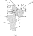
5 die in4 gezeigte Werkzeugkombination in einer Draufsicht und -
6 die in den4 und5 gezeigte Werkzeugkombination in einer seitlichen Schnittdarstellung.
-
1 in a schematic representation and side view of a tillage machine in the form of a road milling machine, -
2 in a side view of a tool combination with a chisel holder, a leading chisel and a first trailing chisel, -
3 in a side view the in2 shown tool combination, mounted on a base part, -
4 in a side view a tool combination with a chisel holder, a leading chisel and a second trailing chisel, -
5 in the4 shown tool combination in a plan view and -
6 in the4 and5 shown tool combination in a side sectional view.
Im Einsatz wird der Maschinenrahmen
Die vorlaufende Meißelspitze
Wie in
Der Meißelhalter
Der vorlaufende Ansatz
Alternativ zu den vier Anlageflächen
Die Anlageflächen
Durch die Drehung der Fräswälze
Ausgehend von der in
Ausgehend von der Drehachse
In
Der zweite nachlaufende Meißel
Der zweite nachlaufende Ansatz
Eine Mittenebene
Bei den in den
Der vorlaufende Meißel
Die nachlaufende Meißelspitze
Der superharte Werkstoff ist vorliegend als polykristalliner Diamant ausgeführt. Er kann entsprechend der vorliegenden Erfindung als Diamantwerkstoff, als diamantverstärkter Werkstoff, als Siliciumcarbid-Werkstoff, als kubisches Bornitrid oder als Verbindungen zumindest zweier der vorgenannten Werkstoffe gebildet sein. Alle diese Werkstoffe oder Werkstoffkombinationen weisen eine größere Härte als das Hartmetall, aus dem der vorlaufende Meißel gefertigt ist, und damit eine größere Beständigkeit gegenüber Verschleiß auf. Neben dem polykristallinen Diamanten kann als Diamantwerkstoff auch ein monokristalliner Diamant, chemisch abgeschiedener Diamant, physikalisch abgeschiedener Diamant, natürlicher Diamant, infiltrierter Diamant, eine oder mehrerer aufeinanderfolgende Diamantschichten, thermisch stabiler Diamant oder siliciumgebundener Diamant verwendet sein.The superhard material is in the present case designed as a polycrystalline diamond. It may be formed according to the present invention as a diamond material, as a diamond-reinforced material, as a silicon carbide material, as a cubic boron nitride or as compounds of at least two of the aforementioned materials. All of these materials or combinations of materials have a greater hardness than the hard metal from which the leading bit is made, and thus greater resistance to wear. In addition to the polycrystalline diamond, the diamond material may also be a monocrystalline diamond, chemically deposited diamond, physically deposited diamond, natural diamond, infiltrated diamond, one or more sequential diamond layers, thermally stable diamond or silicon bonded diamond.
Während eines Fräsprozesses wird die Werkzeugkombination
Zur Durchführung einer Feinfräsung ist beispielsweise eine Eindringtiefe von weniger als 15 mm für den nachlaufenden Meißel
Es ist auch denkbar, das System so auszulegen, dass unter den angenommenen Maschinenparametern der nachlaufende Meißel
Der vorlaufende Meißel
ZITATE ENTHALTEN IN DER BESCHREIBUNG QUOTES INCLUDE IN THE DESCRIPTION
Diese Liste der vom Anmelder aufgeführten Dokumente wurde automatisiert erzeugt und ist ausschließlich zur besseren Information des Lesers aufgenommen. Die Liste ist nicht Bestandteil der deutschen Patent- bzw. Gebrauchsmusteranmeldung. Das DPMA übernimmt keinerlei Haftung für etwaige Fehler oder Auslassungen.This list of the documents listed by the applicant has been generated automatically and is included solely for the better information of the reader. The list is not part of the German patent or utility model application. The DPMA assumes no liability for any errors or omissions.
Zitierte PatentliteraturCited patent literature
- US 4342486 [0002]US 4342486 [0002]
- US 5582468 [0004]US 5582468 [0004]
- WO 2013/064433 [0005]WO 2013/064433 [0005]
Claims (16)
Priority Applications (7)
| Application Number | Priority Date | Filing Date | Title |
|---|---|---|---|
| DE102016125921.7A DE102016125921A1 (en) | 2016-12-30 | 2016-12-30 | Tool combination with a chisel holder and two chisels |
| US16/472,922 US10968577B2 (en) | 2016-12-30 | 2017-11-30 | Tool combination having a chisel holder and two chisels |
| EP17818062.6A EP3563000B1 (en) | 2016-12-30 | 2017-11-30 | Tool combination having a chisel holder and two chisels |
| PCT/EP2017/081017 WO2018121956A1 (en) | 2016-12-30 | 2017-11-30 | Tool combination having a chisel holder and two chisels |
| CN201721881765.6U CN208440958U (en) | 2016-12-30 | 2017-12-28 | The tool combinations being made of chisel holder and leading chisel and the chisel followed |
| TW106146345A TW201822979A (en) | 2016-12-30 | 2017-12-28 | Tool combination having a chisel holder and two chisels |
| CN201711459495.4A CN108265608B (en) | 2016-12-30 | 2017-12-28 | Tool combination with chisel holder and two chisels |
Applications Claiming Priority (1)
| Application Number | Priority Date | Filing Date | Title |
|---|---|---|---|
| DE102016125921.7A DE102016125921A1 (en) | 2016-12-30 | 2016-12-30 | Tool combination with a chisel holder and two chisels |
Publications (1)
| Publication Number | Publication Date |
|---|---|
| DE102016125921A1 true DE102016125921A1 (en) | 2018-07-05 |
Family
ID=60782174
Family Applications (1)
| Application Number | Title | Priority Date | Filing Date |
|---|---|---|---|
| DE102016125921.7A Withdrawn DE102016125921A1 (en) | 2016-12-30 | 2016-12-30 | Tool combination with a chisel holder and two chisels |
Country Status (6)
| Country | Link |
|---|---|
| US (1) | US10968577B2 (en) |
| EP (1) | EP3563000B1 (en) |
| CN (2) | CN208440958U (en) |
| DE (1) | DE102016125921A1 (en) |
| TW (1) | TW201822979A (en) |
| WO (1) | WO2018121956A1 (en) |
Families Citing this family (4)
| Publication number | Priority date | Publication date | Assignee | Title |
|---|---|---|---|---|
| DE102016125921A1 (en) | 2016-12-30 | 2018-07-05 | Wirtgen Gmbh | Tool combination with a chisel holder and two chisels |
| DE102016125917A1 (en) | 2016-12-30 | 2018-07-05 | Wirtgen Gmbh | Tool replacement holder |
| CN111576174A (en) * | 2020-05-31 | 2020-08-25 | 苏州五元素机械制造有限公司 | a chisel |
| USD989137S1 (en) * | 2021-08-05 | 2023-06-13 | Element Six Gmbh | Road milling and planing pick tool |
Citations (3)
| Publication number | Priority date | Publication date | Assignee | Title |
|---|---|---|---|---|
| US4342486A (en) | 1980-09-19 | 1982-08-03 | Joy Manufacturing Company | Cutter bit holder |
| US5582468A (en) | 1995-08-15 | 1996-12-10 | Keystone Engineering & Manufacturing Corporation | Double tooth cutter |
| WO2013064433A2 (en) | 2011-10-31 | 2013-05-10 | Element Six Abrasives S.A. | Tip for a pick tool, method of making same and pick tool comprising same |
Family Cites Families (23)
| Publication number | Priority date | Publication date | Assignee | Title |
|---|---|---|---|---|
| US3614164A (en) * | 1969-08-01 | 1971-10-19 | Carmet Co The | Mine tool adapter |
| US3834764A (en) * | 1972-08-11 | 1974-09-10 | Cincinnati Mine Machinery Co | Core breaking means |
| ZA796174B (en) | 1978-11-25 | 1980-11-26 | Hall & Pickles Ltd | Tools for cutting heads |
| DE2950108C2 (en) * | 1979-12-13 | 1981-12-24 | Halbach & Braun, 5600 Wuppertal | Tool unit for cutting tools |
| US4674802A (en) * | 1982-09-17 | 1987-06-23 | Kennametal, Inc | Multi-insert cutter bit |
| US5374111A (en) | 1993-04-26 | 1994-12-20 | Kennametal Inc. | Extraction undercut for flanged bits |
| DE4322401C2 (en) * | 1993-07-06 | 1996-06-20 | Betek Bergbau & Hartmetall | Attachment of a cutting tool to a cutting body |
| US20010004946A1 (en) | 1997-11-28 | 2001-06-28 | Kenneth M. Jensen | Enhanced non-planar drill insert |
| IL157111A0 (en) | 2003-07-27 | 2004-02-08 | Iscar Ltd | Milling cutter and insert therefor |
| DE102004057302B4 (en) | 2004-11-26 | 2011-01-13 | Wirtgen Gmbh | toolholders |
| DE502005002851D1 (en) * | 2005-10-25 | 2008-03-27 | Bauer Maschinen Gmbh | Milling tooth for a soil cultivator |
| CN1948713A (en) * | 2006-11-06 | 2007-04-18 | 杨晓军 | Wear resistant cutting pick for coal mining and engineering |
| US7959234B2 (en) * | 2008-03-15 | 2011-06-14 | Kennametal Inc. | Rotatable cutting tool with superhard cutting member |
| CN101418686A (en) * | 2008-12-09 | 2009-04-29 | 杨晓军 | A kind of coal mining and engineering pick |
| CN103205958B (en) | 2012-01-16 | 2015-05-20 | 哈姆股份公司 | Roller rollers for ground rollers |
| GB201201120D0 (en) | 2012-01-24 | 2012-03-07 | Element Six Abrasives Sa | Pick tool and assembly comprising same |
| DE102012101719A1 (en) * | 2012-03-01 | 2013-09-05 | Wirtgen Gmbh | toolholders |
| CN202611693U (en) | 2012-06-21 | 2012-12-19 | 中铁隧道装备制造有限公司 | Combined type cantilever heading machine |
| US20140175853A1 (en) * | 2012-12-20 | 2014-06-26 | Esco Hydra (Uk) Limited | Pick For Earthworking Machine |
| US20150211365A1 (en) * | 2014-01-30 | 2015-07-30 | David R. Hall | Multiple Cutters on a Degradation Pick |
| US9752434B2 (en) * | 2014-07-25 | 2017-09-05 | Novatek Ip, Llc | Block capable of supporting multiple picks |
| US10648330B1 (en) * | 2015-09-25 | 2020-05-12 | Us Synthetic Corporation | Cutting tool assemblies including superhard working surfaces, cutting tool mounting assemblies, material-removing machines including the same, and methods of use |
| DE102016125921A1 (en) | 2016-12-30 | 2018-07-05 | Wirtgen Gmbh | Tool combination with a chisel holder and two chisels |
-
2016
- 2016-12-30 DE DE102016125921.7A patent/DE102016125921A1/en not_active Withdrawn
-
2017
- 2017-11-30 EP EP17818062.6A patent/EP3563000B1/en active Active
- 2017-11-30 US US16/472,922 patent/US10968577B2/en active Active
- 2017-11-30 WO PCT/EP2017/081017 patent/WO2018121956A1/en not_active Ceased
- 2017-12-28 CN CN201721881765.6U patent/CN208440958U/en active Active
- 2017-12-28 TW TW106146345A patent/TW201822979A/en unknown
- 2017-12-28 CN CN201711459495.4A patent/CN108265608B/en active Active
Patent Citations (3)
| Publication number | Priority date | Publication date | Assignee | Title |
|---|---|---|---|---|
| US4342486A (en) | 1980-09-19 | 1982-08-03 | Joy Manufacturing Company | Cutter bit holder |
| US5582468A (en) | 1995-08-15 | 1996-12-10 | Keystone Engineering & Manufacturing Corporation | Double tooth cutter |
| WO2013064433A2 (en) | 2011-10-31 | 2013-05-10 | Element Six Abrasives S.A. | Tip for a pick tool, method of making same and pick tool comprising same |
Also Published As
| Publication number | Publication date |
|---|---|
| CN108265608A (en) | 2018-07-10 |
| TW201822979A (en) | 2018-07-01 |
| US20190316304A1 (en) | 2019-10-17 |
| US10968577B2 (en) | 2021-04-06 |
| CN208440958U (en) | 2019-01-29 |
| EP3563000B1 (en) | 2021-03-03 |
| CN108265608B (en) | 2021-06-01 |
| EP3563000A1 (en) | 2019-11-06 |
| WO2018121956A1 (en) | 2018-07-05 |
Similar Documents
| Publication | Publication Date | Title |
|---|---|---|
| AT508232B1 (en) | CUTTING TOOL FOR A MINING MACHINE | |
| EP3670050A1 (en) | Processing segment for a machining tool | |
| EP3563000B1 (en) | Tool combination having a chisel holder and two chisels | |
| EP3670041A1 (en) | Method for producing a segment for dry processing of materials | |
| AT508231B1 (en) | CUTTING DEVICE FOR A MINING MACHINE | |
| DE102011117148A1 (en) | Rotary tool and method of a rotary tool | |
| EP3837076B1 (en) | Chamfering tool | |
| DE4434025C2 (en) | Process for drilling brittle materials, drill for carrying out the process and use of the drill | |
| EP3674025A1 (en) | Processing segment for dry processing of concrete materials | |
| DE102009047913A1 (en) | Grinding machine for grinding workpieces | |
| EP1764176A2 (en) | Milling Tool | |
| EP3670040A1 (en) | Method for producing a segment for dry processing of materials | |
| EP3137254B1 (en) | Tool | |
| EP2679324A2 (en) | Tools and methods for mechanical roughening | |
| EP3563038B1 (en) | Interchangeable chisel holder | |
| DE112008000082B4 (en) | Cutting plate and method for producing a cutting plate | |
| WO2017076669A1 (en) | Tool having a hard material | |
| DE102019117799B4 (en) | Cutting tool with asymmetrical teeth with cutting particles | |
| EP3241948A1 (en) | Rotary milling cutter with a plurality of interchangeable tool heads and tool head for such a rotary milling cutter | |
| EP1004414A2 (en) | Stone cutting tool with PCD cutting segments | |
| EP2789418B1 (en) | Cutting part for a drill | |
| DE102005041331A1 (en) | A method for manufacturing small diameter hardened piercing tools has a cylindrical shaft and head with a hard cap soldered together prior to machining | |
| EP4653112A1 (en) | Wear protection element for a carrier tool | |
| DE2105219C3 (en) | Diamond drill bit | |
| EP1577060B1 (en) | Notching tool |
Legal Events
| Date | Code | Title | Description |
|---|---|---|---|
| R005 | Application deemed withdrawn due to failure to request examination |