DE102016111886A1 - Expandable intervertebral implant - Google Patents
Expandable intervertebral implant Download PDFInfo
- Publication number
- DE102016111886A1 DE102016111886A1 DE102016111886.9A DE102016111886A DE102016111886A1 DE 102016111886 A1 DE102016111886 A1 DE 102016111886A1 DE 102016111886 A DE102016111886 A DE 102016111886A DE 102016111886 A1 DE102016111886 A1 DE 102016111886A1
- Authority
- DE
- Germany
- Prior art keywords
- balloon element
- intervertebral implant
- fluid
- implant according
- outer balloon
- Prior art date
- Legal status (The legal status is an assumption and is not a legal conclusion. Google has not performed a legal analysis and makes no representation as to the accuracy of the status listed.)
- Withdrawn
Links
Images


Classifications
-
- A—HUMAN NECESSITIES
- A61—MEDICAL OR VETERINARY SCIENCE; HYGIENE
- A61B—DIAGNOSIS; SURGERY; IDENTIFICATION
- A61B17/00—Surgical instruments, devices or methods
- A61B17/56—Surgical instruments or methods for treatment of bones or joints; Devices specially adapted therefor
- A61B17/58—Surgical instruments or methods for treatment of bones or joints; Devices specially adapted therefor for osteosynthesis, e.g. bone plates, screws or setting implements
- A61B17/68—Internal fixation devices, including fasteners and spinal fixators, even if a part thereof projects from the skin
- A61B17/70—Spinal positioners or stabilisers, e.g. stabilisers comprising fluid filler in an implant
- A61B17/7097—Stabilisers comprising fluid filler in an implant, e.g. balloon; devices for inserting or filling such implants
-
- A—HUMAN NECESSITIES
- A61—MEDICAL OR VETERINARY SCIENCE; HYGIENE
- A61B—DIAGNOSIS; SURGERY; IDENTIFICATION
- A61B17/00—Surgical instruments, devices or methods
- A61B17/56—Surgical instruments or methods for treatment of bones or joints; Devices specially adapted therefor
- A61B17/58—Surgical instruments or methods for treatment of bones or joints; Devices specially adapted therefor for osteosynthesis, e.g. bone plates, screws or setting implements
- A61B17/88—Osteosynthesis instruments; Methods or means for implanting or extracting internal or external fixation devices
- A61B17/8802—Equipment for handling bone cement or other fluid fillers
- A61B17/8805—Equipment for handling bone cement or other fluid fillers for introducing fluid filler into bone or extracting it
- A61B17/8816—Equipment for handling bone cement or other fluid fillers for introducing fluid filler into bone or extracting it characterised by the conduit, e.g. tube, along which fluid flows into the body or by conduit connections
-
- A—HUMAN NECESSITIES
- A61—MEDICAL OR VETERINARY SCIENCE; HYGIENE
- A61B—DIAGNOSIS; SURGERY; IDENTIFICATION
- A61B17/00—Surgical instruments, devices or methods
- A61B17/56—Surgical instruments or methods for treatment of bones or joints; Devices specially adapted therefor
- A61B17/58—Surgical instruments or methods for treatment of bones or joints; Devices specially adapted therefor for osteosynthesis, e.g. bone plates, screws or setting implements
- A61B17/88—Osteosynthesis instruments; Methods or means for implanting or extracting internal or external fixation devices
- A61B17/885—Tools for expanding or compacting bones or discs or cavities therein
- A61B17/8852—Tools for expanding or compacting bones or discs or cavities therein capable of being assembled or enlarged, or changing shape, inside the bone or disc
- A61B17/8855—Tools for expanding or compacting bones or discs or cavities therein capable of being assembled or enlarged, or changing shape, inside the bone or disc inflatable, e.g. kyphoplasty balloons
-
- A—HUMAN NECESSITIES
- A61—MEDICAL OR VETERINARY SCIENCE; HYGIENE
- A61F—FILTERS IMPLANTABLE INTO BLOOD VESSELS; PROSTHESES; DEVICES PROVIDING PATENCY TO, OR PREVENTING COLLAPSING OF, TUBULAR STRUCTURES OF THE BODY, e.g. STENTS; ORTHOPAEDIC, NURSING OR CONTRACEPTIVE DEVICES; FOMENTATION; TREATMENT OR PROTECTION OF EYES OR EARS; BANDAGES, DRESSINGS OR ABSORBENT PADS; FIRST-AID KITS
- A61F2/00—Filters implantable into blood vessels; Prostheses, i.e. artificial substitutes or replacements for parts of the body; Appliances for connecting them with the body; Devices providing patency to, or preventing collapsing of, tubular structures of the body, e.g. stents
- A61F2/02—Prostheses implantable into the body
- A61F2/30—Joints
- A61F2/44—Joints for the spine, e.g. vertebrae, spinal discs
- A61F2/441—Joints for the spine, e.g. vertebrae, spinal discs made of inflatable pockets or chambers filled with fluid, e.g. with hydrogel
-
- A—HUMAN NECESSITIES
- A61—MEDICAL OR VETERINARY SCIENCE; HYGIENE
- A61F—FILTERS IMPLANTABLE INTO BLOOD VESSELS; PROSTHESES; DEVICES PROVIDING PATENCY TO, OR PREVENTING COLLAPSING OF, TUBULAR STRUCTURES OF THE BODY, e.g. STENTS; ORTHOPAEDIC, NURSING OR CONTRACEPTIVE DEVICES; FOMENTATION; TREATMENT OR PROTECTION OF EYES OR EARS; BANDAGES, DRESSINGS OR ABSORBENT PADS; FIRST-AID KITS
- A61F2/00—Filters implantable into blood vessels; Prostheses, i.e. artificial substitutes or replacements for parts of the body; Appliances for connecting them with the body; Devices providing patency to, or preventing collapsing of, tubular structures of the body, e.g. stents
- A61F2/02—Prostheses implantable into the body
- A61F2/30—Joints
- A61F2002/30001—Additional features of subject-matter classified in A61F2/28, A61F2/30 and subgroups thereof
- A61F2002/30316—The prosthesis having different structural features at different locations within the same prosthesis; Connections between prosthetic parts; Special structural features of bone or joint prostheses not otherwise provided for
- A61F2002/30535—Special structural features of bone or joint prostheses not otherwise provided for
- A61F2002/30581—Special structural features of bone or joint prostheses not otherwise provided for having a pocket filled with fluid, e.g. liquid
- A61F2002/30583—Special structural features of bone or joint prostheses not otherwise provided for having a pocket filled with fluid, e.g. liquid filled with hardenable fluid, e.g. curable in-situ
-
- A—HUMAN NECESSITIES
- A61—MEDICAL OR VETERINARY SCIENCE; HYGIENE
- A61F—FILTERS IMPLANTABLE INTO BLOOD VESSELS; PROSTHESES; DEVICES PROVIDING PATENCY TO, OR PREVENTING COLLAPSING OF, TUBULAR STRUCTURES OF THE BODY, e.g. STENTS; ORTHOPAEDIC, NURSING OR CONTRACEPTIVE DEVICES; FOMENTATION; TREATMENT OR PROTECTION OF EYES OR EARS; BANDAGES, DRESSINGS OR ABSORBENT PADS; FIRST-AID KITS
- A61F2/00—Filters implantable into blood vessels; Prostheses, i.e. artificial substitutes or replacements for parts of the body; Appliances for connecting them with the body; Devices providing patency to, or preventing collapsing of, tubular structures of the body, e.g. stents
- A61F2/02—Prostheses implantable into the body
- A61F2/30—Joints
- A61F2002/30001—Additional features of subject-matter classified in A61F2/28, A61F2/30 and subgroups thereof
- A61F2002/30316—The prosthesis having different structural features at different locations within the same prosthesis; Connections between prosthetic parts; Special structural features of bone or joint prostheses not otherwise provided for
- A61F2002/30535—Special structural features of bone or joint prostheses not otherwise provided for
- A61F2002/30581—Special structural features of bone or joint prostheses not otherwise provided for having a pocket filled with fluid, e.g. liquid
- A61F2002/30586—Special structural features of bone or joint prostheses not otherwise provided for having a pocket filled with fluid, e.g. liquid having two or more inflatable pockets or chambers
Landscapes
- Health & Medical Sciences (AREA)
- Orthopedic Medicine & Surgery (AREA)
- Life Sciences & Earth Sciences (AREA)
- Surgery (AREA)
- Biomedical Technology (AREA)
- Engineering & Computer Science (AREA)
- Public Health (AREA)
- Heart & Thoracic Surgery (AREA)
- General Health & Medical Sciences (AREA)
- Animal Behavior & Ethology (AREA)
- Veterinary Medicine (AREA)
- Molecular Biology (AREA)
- Medical Informatics (AREA)
- Nuclear Medicine, Radiotherapy & Molecular Imaging (AREA)
- Neurology (AREA)
- Oral & Maxillofacial Surgery (AREA)
- Vascular Medicine (AREA)
- Physics & Mathematics (AREA)
- Fluid Mechanics (AREA)
- Transplantation (AREA)
- Chemical & Material Sciences (AREA)
- Cardiology (AREA)
- Dispersion Chemistry (AREA)
- Prostheses (AREA)
Abstract
Die Erfindung betrifft ein expandierbares Zwischenwirbelimplantat (2) für den Bandscheibenersatz, insbesondere im thorakalen und lumbalen Wirbelsäulenbereich, mit einem inneren Ballonelement (4) und einem äußeren Ballonelement (6), wobei das innere und das äußere Ballonelement jeweils für sich mittels eines injizierbaren fluiden und aushärtbaren Mediums füllbar sind, wobei das äußere Ballonelement (6) beim Einbringen in ein Bandscheibenfach in einem Zwischenwirbelbereich als Bandscheibenersatz ungefähr die Gestalt der zuvor entfernten Bandscheibe einnehmen soll, und eine obere und eine untere Wandung umfasst, mittels derer es im injizierten Zustand gegen eine das Bandscheibenfach oben und unten begrenzende Seite der angrenzenden Wirbelkörper anlegbar ist, und wobei das innere Ballonelement (4) eine anteriore oder posteriore oder parallele Bandscheibenfacherhöhung bewirkt, indem es im injizierten Zustand von innen gegen das äußere Ballonelement (6) mittelbar oder unmittelbar stützend anliegt.The invention relates to an expandable intervertebral implant (2) for the intervertebral disc replacement, in particular in the thoracic and lumbar spine region, with an inner balloon member (4) and an outer balloon member (6), wherein the inner and the outer balloon member individually by means of an injectable fluid and hardenable medium can be filled, wherein the outer balloon member (6) when inserted into a disc space in an intervertebral space as an intervertebral disc replacement to take approximately the shape of the previously removed disc, and an upper and a lower wall, by means of which it in the injected state against a Intervertebral disc compartment can be applied to the upper and lower bordering side of the adjacent vertebral bodies, and wherein the inner balloon element (4) causes an anterior or posterior or parallel intervertebral disc elevation by being in the injected state from the inside against the outer balloon element (6) indirectly or unmitte lbar supporting.
Description
Die Erfindung betrifft ein expandierbares Zwischenwirbelimplantat für den Bandscheibenersatz, insbesondere im thorakalen und lumbalen Wirbelsäulenbereich.The invention relates to an expandable intervertebral implant for intervertebral disc replacement, in particular in the thoracic and lumbar spine area.
Als Bandscheibenersatz wurden bislang sogenannte "Cages" verwendet, die in verschiedener Weise an die erwünschte Gestalt des Bandscheibenfachs angepasst werden können, indem die relative Position ihrer oberen und unteren Wandung zueinander durch verschiedene Mechanismen einstellbar ist. So-called "cages" have heretofore been used as an intervertebral disk replacement, which can be adapted in various ways to the desired shape of the intervertebral disc compartment by the relative position of its upper and lower walls being adjustable by different mechanisms.
Der vorliegenden Erfindung liegt die Aufgabe zugrunde, ein expandieres Zwischenwirbelimplantat für den Bandscheibenersatz bereitzustellen, mit dem einerseits eine optimale Anpassung des Implantats an das auszufüllende Bandscheibenfach möglich ist und andererseits das Bandscheibenfach wie vom Chirurgen intendiert gestützt oder aufgeweitet werden kann und in diesem distrahierten Zustand dauerhaft stabilisiert werden kann.The present invention has for its object to provide an expansive intervertebral implant for the intervertebral disc replacement, on the one hand optimal adaptation of the implant to the intervertebral disc space is possible and on the other hand, the intervertebral disc as intended by the surgeon can be supported or expanded and permanently stabilized in this distracted state can be.
Diese Aufgabe wird erfindungsgemäß gelöst durch ein expandierbares Zwischenwirbelimplantat für den Bandscheibenersatz, insbesondere im thorakalen und lumbalen Wirbelsäulenbereich, mit einem inneren Ballonelement und einem äußeren Ballonelement, wobei das innere und das äußere Ballonelement jeweils für sich mittels eines injizierbaren fluiden und aushärtbaren Mediums füllbar sind, wobei das äußere Ballonelement beim Einbringen in ein Bandscheibenfach in einem Zwischenwirbelbereich als Bandscheibenersatz ungefähr die Gestalt oder Teile der zuvor entfernten Bandscheibe einnehmen soll, und eine obere und eine untere Wandung umfasst, mittels derer es im injizierten Zustand gegen eine das Bandscheibenfach oben und unten begrenzende Seite der angrenzenden Wirbelkörper anlegbar ist, und wobei das innere Ballonelement eine anteriore oder posteriore oder parallele Bandscheibenfacherhöhung bewirkt, indem es im injizierten Zustand von innen gegen das äußere Ballonelement mittelbar oder unmittelbar stützend anliegt.This object is achieved by an expandable intervertebral implant for the intervertebral disc replacement, especially in the thoracic and lumbar spine area, with an inner balloon member and an outer balloon member, wherein the inner and the outer balloon element can be filled individually by means of an injectable fluid and curable medium, wherein the outer balloon member when inserting into an intervertebral disc space in an intervertebral space as intervertebral disc replacement is about to occupy the shape or parts of the previously removed disc, and an upper and a lower wall, by means of which it in the injected state against the disc compartment top and bottom bounding side of the adjoining vertebral body can be applied, and wherein the inner balloon member causes an anterior or posterior or parallel intervertebral disc compartment elevation by mediating it in the injected state from the inside against the outer balloon member ar or immediately supporting.
Erfindungsgemäß ist also das äußere Ballonelement entsprechend der zu ersetzenden Bandscheibe ausgebildet, es weist im befüllten oder injizierten Zustand eine scheibenförmige, der ungefähren Kontur der Bandscheibe folgende Gestalt auf, wobei das äußere Ballonelement im injizierten Zustand und je nach Positionierung und Befüllungszustand des inneren Ballonelements eine variierende vom Chirurgen individuell einstellbare Höhe in spinaler Richtung aufweist. Je nach Anordnung oder Positionierung des inneren Ballonelements innerhalb äußeren Ballonelements in anteriorer oder posteriorer Richtung und je nach Befüllung des inneren Ballonelements kann mittels des inneren Ballonelements eine anteriore oder posteriore oder parallele Bandscheibenfacherhöhung bewirkt werden, insbesondere entsprechend einer zu korrigierenden Lordose oder Kyphose oder auch Spinose. Dabei wird in der Operationssituation zunächst das Zwischenwirbelimplantat im zu distrahierenden Bandscheibenfach angeordnet, und dann wird das innere Ballonelement durch Injizieren des fluiden und aushärtbaren Mediums derart befüllt, dass es unten und oben gegen die Innenseite des äußeren Ballonelements unter Kraftausübung anliegt und hierdurch eine Erhöhung oder Veränderung des Bandscheibenfachs erreichen kann.According to the invention, therefore, the outer balloon element is designed according to the intervertebral disc to be replaced, it has a disc-shaped in the filled or injected state, the approximate contour of the intervertebral disk following shape, wherein the outer balloon member in the injected state and depending on the positioning and filling state of the inner balloon member is a varying by the surgeon individually adjustable height in the spinal direction. Depending on the arrangement or positioning of the inner balloon element within the outer balloon element in the anterior or posterior direction and depending on the filling of the inner balloon element, an anterior or posterior or parallel intervertebral-disc elevation can be effected by means of the inner balloon element, in particular according to a lordosis or kyphosis or spinose to be corrected. In this case, in the surgical situation, the intervertebral implant is first placed in the disc space to be distracted, and then the inner balloon element is filled by injecting the fluid and hardenable medium so that it rests against the inside of the outer balloon element under force and thus an increase or change of the disc compartment can reach.
Wie bereits erwähnt, weist das äußere Ballonelement im injizierten, mit fluidem Medium ausgefüllten Zustand eine scheibenförmige Gestalt auf. Es erweist sich als vorteilhaft, wenn zwischen der oberen und unteren Wandung eine ungefähr streifenförmige in einer Umfangsrichtung erstreckte Seitenwandung vorgesehen ist, welche oben und unten in die obere bzw. untere Wandung anschließt. As already mentioned, the outer balloon element has a disk-like shape in the injected, fluid-filled state. It proves to be advantageous if an approximately strip-shaped in a circumferential direction extending side wall is provided between the upper and lower wall, which connects up and down in the upper and lower walls.
Weiter erweist es sich als vorteilhaft, wenn das äußere und vorzugsweise auch das innere Ballonelement im injizierten Zustand eine Vorzugskontur einnimmt. Diese der grundsätzlichen Bandscheibenkontur entsprechende Vorzugskontur kann beispielsweise dadurch realisiert werden, dass Flachmaterialabschnitte entsprechend zugeschnitten und zur Bildung des Ballonelements aneinander gefügt werden. Es ist auch denkbar und vorteilhaft, wenn in Flachmaterialabschnitte Drähte, Lamellen, Fasern, Filamente oder hieraus gewobene Flachmaterialstrukturen eingebracht werden, welche die Ausbildung einer Vorzugskontur bewirken oder unterstützen. Beispielsweise können biegsame Drähte, wie Nitinol (Nickel-Titan-Legierung), entlang des Außenumfangs der oberen und unteren Wandungen eingebracht werden. Metallische Drähte haben den Vorteil, dass sie unter Röntgenkontrolle sichtbar sind. Es wäre auch denkbar, dass die in der Umfangsrichtung erstreckte Seitenwandung des äußeren Ballonelements eine höhere Steifigkeit als die obere oder untere Wandung aufweist, welche der Formstabilität dient.Furthermore, it proves to be advantageous if the outer and preferably also the inner balloon element occupies a preferred contour in the injected state. This preferred contour corresponding to the basic intervertebral disc contour can be realized, for example, by correspondingly cutting flat material sections and joining them together to form the balloon element. It is also conceivable and advantageous if in flat material sections wires, fins, fibers, filaments or woven flat material structures are introduced, which cause or support the formation of a preferred contour. For example, flexible wires such as nitinol (nickel-titanium alloy) may be introduced along the outer perimeter of the upper and lower walls. Metallic wires have the advantage that they are visible under X-ray control. It would also be conceivable that the circumferentially extending side wall of the outer balloon member has a higher rigidity than the upper or lower wall, which serves the dimensional stability.
Weiter erweist es sich als vorteilhaft, dass im Inneren des äußeren Ballonelements ein anterior angeordnetes und ein posterior angeordnetes inneres Ballonelement vorgesehen sind. Auf diese Weise kann durch Befüllen des anterior bzw. posterior angeordneten inneren Ballonelements auf sehr einfache Weise gezielt eine erwünschte Erhöhung des Bandscheibenfachs anterior oder posterior erreicht werden, insbesondere um eine Lordose oder Kyphose zu korrigieren. Alternativ wäre es denkbar, dass je nach zu erzielender Bandscheibenfachaufweitung ein Zwischenwirbelimplantat mit einem posterior angeordneten bzw. alternativ mit einem anterior angeordneten inneren Ballonelement verwendet wird. Es wäre auch denkbar, dass das innere Ballonelement in anteriorer bzw. posteriorer Richtung innerhalb des äußeren Ballonelements verschieblich positionierbar ist. Furthermore, it proves to be advantageous that an anterior arranged and a posteriorly arranged inner balloon element are provided in the interior of the outer balloon element. In this way, by filling the anterior or posteriorly disposed inner balloon element in a very simple manner, a desired increase in the anterior or posterior disc space can be specifically achieved, in particular to correct a lordosis or kyphosis. Alternatively, it would be conceivable that an intervertebral implant with a posteriorly arranged or alternatively arranged with an anterior inner balloon element is used, depending on the intervertebral disc expansion to be achieved. It It would also be conceivable for the inner balloon element to be displaceably positionable in the anterior or posterior direction within the outer balloon element.
Es erweist sich weiter als vorteilhaft, wenn von dem inneren Ballonelement ein leitungsbildendes Verbindungselement nach außerhalb des äußeren Ballons führt, an welches ein Instrument zum Injizieren des fluiden und aushärtbaren Mediums lösbar ankoppelbar ist.It also proves to be advantageous if a conduit-forming connecting element leads out of the inner balloon element to the outside of the outer balloon, to which an instrument for injecting the fluid and hardenable medium can be detachably coupled.
Es erweist sich als vorteilhaft, wenn das mit dem inneren Ballonelement kommunizierende leitungsbildende Verbindungselement ein Ventil umfasst, welches bei von außen anliegendem Injektionsdruck öffnet und bei Wegnahme des von außen anliegenden Injektionsdrucks schließt. Dies bringt den Vorteil mit sich, dass das innere Ballonelement beim Befüllen des äußeren Ballonelements nicht zwingend unter Injektionsdruck gehalten werden muss, was die Implantation vereinfacht. In Weiterbildung dieses Erfindungsgedankens erweist es sich als vorteilhaft, wenn das Ventil dadurch öffenbar ist, dass ein Ventilkörper des Ventils von außen mittels einer Kanüle, durch die das fluide und aushärtbare Medium injizierbar ist, verdrängt wird. Wenn die Kanüle dann geringfügig zurückbewegt wird, so bewirkt der Fülldruck im Inneren des inneren Ballonelements, dass der Ventilkörper des Ventils wieder von innen gegen seinen Ventilsitz dichtend angelegt wird. It proves to be advantageous if the line-forming connecting element communicating with the inner balloon element comprises a valve which opens when the injection pressure is applied from the outside and closes when the injection pressure applied from the outside is removed. This has the advantage that the inner balloon element does not necessarily have to be held under injection pressure when filling the outer balloon element, which simplifies the implantation. In a further development of this inventive idea, it proves to be advantageous if the valve can be opened by displacing a valve body of the valve from the outside by means of a cannula, through which the fluid and hardenable medium can be injected. When the cannula is then moved back slightly, the filling pressure in the interior of the inner balloon element causes the valve body of the valve to be re-sealed from the inside against its valve seat.
Nach einem weiteren Erfindungsgedanken von wesentlicher Bedeutung erweist es sich als vorteilhaft, dass das leitungsbildende Verbindungselement in einem Bereich zwischen einer Außenseite des inneren Ballonelements und einer Innenseite der äußeren Ballonelements eine Öffnung zum Injizieren des fluiden und aushärtbaren Mediums in das Innere des äußeren Ballonelements aufweist. Es ist also möglich, unter Verwendung ein und desselben leitungsbildenden Verbindungselements sowohl das innere Ballonelement als auch das äußere Ballonelement mit fluidem aushärtbarem Medium zu befüllen (injizieren) und dadurch eine Distraktion des Bandscheibenfachs herbeizuführen. According to a further inventive concept of essential importance, it proves to be advantageous that the conduit-forming connecting element has an opening for injecting the fluid and hardenable medium into the interior of the outer balloon element in a region between an outer side of the inner balloon element and an inner side of the outer balloon element. It is thus possible to fill (inject) both the inner balloon element and the outer balloon element with fluid curable medium using one and the same conduit-forming connecting element, thereby causing distraction of the intervertebral-space.
Hierbei erweist es sich als vorteilhaft, dass die Öffnung zum Injizieren des fluiden und aushärtbaren Mediums in das äußere Ballonelement beim Injizieren des fluiden und aushärtbaren Mediums in das innere Ballonelement verschließbar ist.It proves to be advantageous that the opening for injecting the fluid and hardenable medium into the outer balloon element during injection of the fluid and curable medium in the inner balloon element is closed.
Dies kann in vorteilhafter Weise dadurch realisiert werden, dass die Öffnung zum Injizieren des fluiden und aushärtbaren Mediums in das äußere Ballonelement durch eine Kanüle, durch die das fluide und aushärtbare Medium injizierbar ist, verschließbar und freigebbar ist. This can be advantageously realized by closing and releasing the opening for injecting the fluid and hardenable medium into the outer balloon member through a cannula through which the fluid and hardenable medium is injectable.
Weiter erweist es sich als vorteilhaft, wenn das leitungsbildende Verbindungselement gegenüber dem äußeren Ballonelement längenverstellbar ist, so dass das innere Ballonelement nach anterior oder posterior verlagerbar ist. Furthermore, it proves to be advantageous if the line-forming connecting element is adjustable in length relative to the outer balloon element, so that the inner balloon element is displaceable anteriorly or posteriorly.
Es wäre auch denkbar, dass jedem Ballonelement ein leitungsbildendes Verbindungselement zugeordnet ist, an welches ein Instrument zum Injizieren des fluiden und aushärtbaren Mediums lösbar ankoppelbar ist. It would also be conceivable that each balloon element is associated with a line-forming connecting element, to which an instrument for injecting the fluid and curable medium is detachably coupled.
Nach einem weiteren Erfindungsgedanken von wesentlicher Bedeutung erweist es sich als vorteilhaft, wenn das Zwischenwirbelimplantat mit einer Osteosynthesevorrichtung verbindbar ist, die an wenigstens einem angrenzenden Wirbelkörper fixierbar ist. Durch Verbindung oder Anbindung des Zwischenwirbelimplantats an eine Osteosynthesevorrichtung kann eine gemeinsam handhabbare Einrichtung geschaffen werden, durch die das Zwischenwirbelimplantat mittels der Osteosynthesevorrichtung gehalten und eingebracht werden kann. Diese Halteverbindung kann in vorteilhafter Weise dadurch realisiert werden, dass das Zwischenwirbelimplantat und die Osteosynthesevorrichtung mittels des leitungsbildenden Verbindungselements miteinander verbunden sind. According to a further concept of the invention of essential importance, it proves to be advantageous if the intervertebral implant can be connected to an osteosynthesis device which can be fixed to at least one adjoining vertebral body. By connecting or connecting the intervertebral implant to an osteosynthesis device, a jointly manageable device can be created, by means of which the intervertebral implant can be held and inserted by means of the osteosynthesis device. This holding connection can be realized in an advantageous manner in that the intervertebral implant and the osteosynthesis device are connected to one another by means of the line-forming connecting element.
Bei dem injizierbaren fluiden und aushärtbaren Medium kann es sich in vorteilhafter Weise um PMMA (Knochenzement), Hydrogel, Silikon und/oder Calciumphosphat (CaP) und gegebenenfalls partikuläre Füllstoffe handeln. The injectable fluid and hardenable medium may advantageously be PMMA (bone cement), hydrogel, silicone and / or calcium phosphate (CaP) and optionally particulate fillers.
Weiter erweist es sich als vorteilhaft, wenn das äußere Ballonelement eine äußere Beschichtung mit Titan oder Titanlegierung, mit Hydroxylapatit (HA), mit Polylactid (PLA), mit Calciumphosphat (CaP), mit BMP (Bone Morphogenetic Protein = knochenmorphogenetische Proteine), und/oder mit Silber oder einer Silberverbindung aufweist. Hierdurch kann eine stabilere bzw. integrative Verbindung zwischen dem äußeren Ballonelement und dem Knochen erreicht werden. Dies wird auf eine verbesserte biologische Interaktion zwischen dem Ballonelement und dem Knochengewebe zurückgeführt. Hierfür ist es auch denkbar, dass das äußere Ballonelement außen eine Nano-, Mikro- oder Makrostrukturierung aufweist, die beispielsweise durch Ätz- oder Laserverfahren hergestellt werden kann, oder außen spikeartige Vorsprünge aufweist, die sich in den angrenzenden Knochen eingraben und verankern können. Furthermore, it proves to be advantageous if the outer balloon element has an outer coating with titanium or titanium alloy, with hydroxyapatite (HA), with polylactide (PLA), with calcium phosphate (CaP), with BMP (Bone Morphogenetic Protein = bone morphogenetic proteins), and / or with silver or a silver compound. As a result, a more stable or integrative connection between the outer balloon element and the bone can be achieved. This is attributed to improved biological interaction between the balloon member and the bone tissue. For this purpose, it is also conceivable that the outer balloon element externally has a nano-, micro- or Makrostrukturierung, which can be prepared for example by etching or laser process, or outside spikeartige projections has that dig into the adjacent bone and can anchor.
Es erweist sich auch als besonders vorteilhaft, wenn das äußere Ballonelement zumindest bereichsweise in der oberen und/oder unteren Wandung Öffnungen aufweist, die oberhalb eines Innendrucks für das injizierte Medium durchlässig werden, so dass das injizierte Medium die Öffnungen durchdringen und in angrenzende poröse Knochenbereiche eindringen kann. It also proves to be particularly advantageous if the outer balloon element at least partially in the upper and / or lower wall has openings which are permeable above an internal pressure for the injected medium, so that the injected medium, the openings penetrate and penetrate into adjacent porous bone areas.
Zu diesem Zweck erweist es sich auch als vorteilhaft, wenn wenigstens eine zusätzliche Zuführleitung für das injizierbare fluide und aushärtbare Medium vorgesehen ist, die in der oberen und/oder unteren Wandung des äußeren Ballonelements nach außen mündet, so dass das injizierte Medium in angrenzende poröse Knochenbereiche eindringen kann. Insbesondere kann das leitungsbildende Verbindungselement diese Zuführleitung umfassen oder mit ihr kommunizieren.For this purpose, it is also advantageous if at least one additional supply line for the injectable fluid and curable medium is provided, which opens outwards in the upper and / or lower wall of the outer balloon element, so that the injected medium into adjacent porous bone areas can penetrate. In particular, the line-forming connecting element can comprise or communicate with this supply line.
Es wird auch Schutz beansprucht für ein Instrument zum Befüllen des inneren oder äußeren Ballonelements und für eine Sachgesamtheit aus einem erfindungsgemäßen expandierbaren Zwischenwirbelimplantat und einem solchen Instrument zum Injizieren des fluiden und aushärtbaren Mediums in das innere und das äußere Ballonelement mit den Merkmalen des Anspruchs 20. Protection is also claimed for an instrument for filling the inner or outer balloon member and an assembly of an expandable intervertebral implant according to the invention and such an instrument for injecting the fluid and hardenable medium into the inner and outer balloon members having the features of
Durch das Verschieben der Kanüle des Instruments kann die Kanüle in eine Injektionsstellung in Bezug auf das innere oder das äußere Ballonelement gebracht werden. Beispielsweise vermag sie in einer Injektionsstellung für das innere Ballonelement das dort vorgesehene Ventil zu öffnen und in einer zurückgezogenen Position zu verschließen.By moving the cannula of the instrument, the cannula can be brought into an injection position with respect to the inner or the outer balloon element. For example, it is able to open the valve provided there in an injection position for the inner balloon element and to close it in a retracted position.
Es erweist sich auch als vorteilhaft, wenn die Kanüle in der äußeren Hülse in einer Längsrichtung begrenzt verschieblich ist, indem sie wenigstens einen radialen Vorsprung aufweist, der in einer von einem Griffelement der äußeren Hülse begrenzten Kammer gegen einen Axialanschlag oder vorzugsweise in beiden Richtungen gegen je einen Axialanschlag anlegbar ist. Auf diese Weise kann eine Injektionsposition eingenommen bzw. verlassen werden.It also proves to be advantageous if the cannula in the outer sleeve is limitedly displaceable in a longitudinal direction, by having at least one radial projection in a limited by a handle member of the outer sleeve chamber against an axial stop or preferably in both directions against each an axial stop can be applied. In this way, an injection position can be taken or left.
Weiter kann es sich als vorteilhaft erweisen, wenn die Kanüle des Instruments in der äußeren Hülse in einer Längsrichtung drehbar ist und eine seitliche Fluidaustrittsöffnung aufweist, die durch Drehung in eine fluchtende Anordnung mit der Öffnung in dem leitungsbildenden Verbindungselement bringbar ist, so dass durch Drehung der Kanüle eine Fluidkommunikation zum Infiltrieren des äußeren Ballonelements herstellbar und blockierbar ist. Somit kann die Öffnung zum Befüllen des äußeren Ballonelements freigegeben oder verschlossen werden.Further, it may prove advantageous if the cannula of the instrument is rotatable in the outer sleeve in a longitudinal direction and has a lateral fluid outlet opening which can be brought by rotation in an aligned arrangement with the opening in the lead-forming connecting element, so that by rotation of Cannula fluid communication for infiltrating the outer balloon member can be produced and blocked. Thus, the opening for filling the outer balloon member can be released or closed.
Nach einer weiteren Ausführungsform der Erfindung ist vorgesehen, dass die Kanüle in der äußeren Hülse an Ihrem ballonseitigen Ende geschlossen ist und in einer Längsrichtung drehbar ist und eine oder mehrere seitliche Fluidaustrittsöffnung aufweist, die durch Drehung in eine fluchtende Anordnung mit wenigstens einer Öffnung in dem leitungsbildenden Verbindungselement bringbar ist, wobei diese wenigstens eine Öffnung mit dem Inneren eines Ballonelements kommuniziert, so dass durch Drehung der Kanüle eine Fluidkommunikation zum Infiltrieren eines oder mehrerer Ballonelemente herstellbar und blockierbar ist. According to a further embodiment of the invention, it is provided that the cannula is closed in the outer sleeve at its balloon end and is rotatable in a longitudinal direction and has one or more lateral fluid outlet opening which by rotation in an aligned arrangement with at least one opening in the conduit forming Can be brought connecting element, said at least one opening communicates with the interior of a balloon element, so that by rotation of the cannula fluid communication for infiltrating one or more balloon elements can be produced and blocked.
Weitere Merkmale, Einzelheiten und Vorteile der Erfindung ergeben sich aus den beigefügten Patentansprüchen und aus der zeichnerischen Darstellung und nachfolgenden Beschreibung verschiedener Ausführungsformen der Erfindung. Further features, details and advantages of the invention will become apparent from the appended claims and from the drawings and the description below of various embodiments of the invention.
In der Zeichnung zeigt:In the drawing shows:
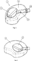
Die
Wird der Fülldruck in dem leitungsbildenden Verbindungselement
In
Die
Durch dieses Verschieben der Zementierungskanüle
Durch geeignete Ausbildung des leitungsbildenden Verbindungselements
Es ist auch denkbar (nicht dargestellt), dass die Zementierungskanüle an ihrem distalen Ende verschlossen oder verschließbar ist und selbst wenigstens eine seitliche Austrittsöffnung für das zu injizierende fluide oder aushärtbare Medium aufweist. Auf diese Weise kann durch Drehen der Zementierungshülse innerhalb der Applikatorhülse eine fluchtende Anordnung der Öffnung in der Zementierungshülse mit der Durchgangsöffnung
Die
Claims (23)
Priority Applications (3)
| Application Number | Priority Date | Filing Date | Title |
|---|---|---|---|
| DE102016111886.9A DE102016111886A1 (en) | 2016-06-29 | 2016-06-29 | Expandable intervertebral implant |
| EP17736605.1A EP3478195B1 (en) | 2016-06-29 | 2017-06-28 | Expandable intervertebral implant |
| PCT/EP2017/066003 WO2018002145A1 (en) | 2016-06-29 | 2017-06-28 | Expandable intervertebral implant |
Applications Claiming Priority (1)
| Application Number | Priority Date | Filing Date | Title |
|---|---|---|---|
| DE102016111886.9A DE102016111886A1 (en) | 2016-06-29 | 2016-06-29 | Expandable intervertebral implant |
Publications (1)
| Publication Number | Publication Date |
|---|---|
| DE102016111886A1 true DE102016111886A1 (en) | 2018-01-04 |
Family
ID=59295179
Family Applications (1)
| Application Number | Title | Priority Date | Filing Date |
|---|---|---|---|
| DE102016111886.9A Withdrawn DE102016111886A1 (en) | 2016-06-29 | 2016-06-29 | Expandable intervertebral implant |
Country Status (3)
| Country | Link |
|---|---|
| EP (1) | EP3478195B1 (en) |
| DE (1) | DE102016111886A1 (en) |
| WO (1) | WO2018002145A1 (en) |
Cited By (1)
| Publication number | Priority date | Publication date | Assignee | Title |
|---|---|---|---|---|
| WO2021205357A1 (en) * | 2020-04-07 | 2021-10-14 | Ethicon, Inc. | Cortical rim-supporting interbody device |
Families Citing this family (2)
| Publication number | Priority date | Publication date | Assignee | Title |
|---|---|---|---|---|
| EP4036063A4 (en) * | 2019-09-27 | 2022-11-23 | Panasonic Intellectual Property Management Co., Ltd. | Method for producing lithium-nickel complex oxide |
| CN113558740B (en) * | 2021-08-04 | 2023-07-14 | 西安市红会医院 | A self-stirring pusher for bone cement for vertebral body shaping |
Citations (4)
| Publication number | Priority date | Publication date | Assignee | Title |
|---|---|---|---|---|
| US20050027358A1 (en) * | 2003-07-29 | 2005-02-03 | Loubert Suddaby | Inflatable nuclear prosthesis |
| US20090259177A1 (en) * | 2005-02-16 | 2009-10-15 | Susan Lynn Riley | Resorbable hollow devices for implantation and delivery of therapeutic agents |
| US20160022344A1 (en) * | 2013-04-01 | 2016-01-28 | Terumo Kabushiki Kaisha | Spacer, implant assembly including the same, manufacturing method of spacer, and surgical method for spacer indwelling |
| US20160120653A1 (en) * | 2014-11-04 | 2016-05-05 | Spinal Stabilization Technologies Llc | Percutaneous Implantable Nuclear Prosthesis |
Family Cites Families (4)
| Publication number | Priority date | Publication date | Assignee | Title |
|---|---|---|---|---|
| US7645301B2 (en) * | 2006-01-13 | 2010-01-12 | Zimmer Spine, Inc. | Devices and methods for disc replacement |
| US7879027B2 (en) * | 2006-04-24 | 2011-02-01 | Warsaw Orthopedic, Inc. | Controlled release devices for fusion of osteal structures |
| US8236057B2 (en) * | 2006-06-12 | 2012-08-07 | Globus Medical, Inc. | Inflatable multi-chambered devices and methods of treatment using the same |
| US9526538B2 (en) * | 2009-12-07 | 2016-12-27 | Globus Medical, Inc. | Methods and apparatus for treating vertebral fractures |
-
2016
- 2016-06-29 DE DE102016111886.9A patent/DE102016111886A1/en not_active Withdrawn
-
2017
- 2017-06-28 WO PCT/EP2017/066003 patent/WO2018002145A1/en not_active Ceased
- 2017-06-28 EP EP17736605.1A patent/EP3478195B1/en active Active
Patent Citations (4)
| Publication number | Priority date | Publication date | Assignee | Title |
|---|---|---|---|---|
| US20050027358A1 (en) * | 2003-07-29 | 2005-02-03 | Loubert Suddaby | Inflatable nuclear prosthesis |
| US20090259177A1 (en) * | 2005-02-16 | 2009-10-15 | Susan Lynn Riley | Resorbable hollow devices for implantation and delivery of therapeutic agents |
| US20160022344A1 (en) * | 2013-04-01 | 2016-01-28 | Terumo Kabushiki Kaisha | Spacer, implant assembly including the same, manufacturing method of spacer, and surgical method for spacer indwelling |
| US20160120653A1 (en) * | 2014-11-04 | 2016-05-05 | Spinal Stabilization Technologies Llc | Percutaneous Implantable Nuclear Prosthesis |
Cited By (5)
| Publication number | Priority date | Publication date | Assignee | Title |
|---|---|---|---|---|
| WO2021205357A1 (en) * | 2020-04-07 | 2021-10-14 | Ethicon, Inc. | Cortical rim-supporting interbody device |
| CN115701947A (en) * | 2020-04-07 | 2023-02-14 | 爱惜康股份有限公司 | Cortical rim supporting interbody device |
| JP2023521084A (en) * | 2020-04-07 | 2023-05-23 | エシコン・インコーポレイテッド | Interbody device supporting the cortical rim |
| US12053391B2 (en) | 2020-04-07 | 2024-08-06 | Ethicon, Inc. | Cortical rim-supporting interbody device and method |
| JP7731900B2 (en) | 2020-04-07 | 2025-09-01 | エシコン・インコーポレイテッド | Cortical rim-supporting interbody devices |
Also Published As
| Publication number | Publication date |
|---|---|
| WO2018002145A1 (en) | 2018-01-04 |
| EP3478195A1 (en) | 2019-05-08 |
| EP3478195B1 (en) | 2020-01-01 |
Similar Documents
| Publication | Publication Date | Title |
|---|---|---|
| DE60320464T2 (en) | Vertebral distractor | |
| EP2826446B1 (en) | Operating tool for an implant | |
| US6740093B2 (en) | Method and apparatus for treating a vertebral body | |
| AU2010236479B2 (en) | Minimally invasive expandable contained vertebral implant and method | |
| DE10253170A1 (en) | Implant used in procedures for stiffening the vertebral column consists of a compression-resistant hollow body made from two open receptacles which are pressed apart with insertion of filler material | |
| EP2696811A1 (en) | Intervertebral implant and insertion device | |
| DE102009014184A1 (en) | Implant for fusion of spinal segments | |
| WO2002030338A1 (en) | Method and appartus for treating a vertebral body | |
| EP2829242A1 (en) | System for anchoring a pedicle screw, associated kit, spacer and pedicle graft | |
| WO2005004756A2 (en) | Intervertebral disk prosthesis | |
| JP2010512847A (en) | Confinement device for vertebral implant and method of use | |
| EP3478195B1 (en) | Expandable intervertebral implant | |
| EP3331472B1 (en) | Implant for sealing a defect in the anulus fibrosus of an intervertebral disc | |
| US10420652B2 (en) | Bone scaffold improvements | |
| DE102012203256A1 (en) | Implant structure for supporting spine in inter vertebral space, has anterior support element and posterior support element that are connected with adjusting mechanism where support elements are spaced apart at a distance | |
| DE60310218T2 (en) | Fillable implant and system for treating a deformed or pathologically altered spine | |
| DE10309986B4 (en) | Implant, implant system for rebuilding a vertebral body | |
| WO2006099969A2 (en) | Method and device for the production of spinal implants | |
| EP2417939B1 (en) | Spinal prosthesis | |
| DE102015223483A1 (en) | Medical implant for connecting two bones | |
| WO2016065490A1 (en) | Device for applying bone replacement pastes | |
| DE102011117724A1 (en) | Device for supporting spinal column in region of transverse projections of two adjacent vertebrae during minimally invasive surgery of patient, has lateral extension larger in operating state than that of device in another operating state | |
| DE202009005850U1 (en) | Press for a plastic implant for insertion between vertebral bodies of the spine | |
| NZ731593B2 (en) | Bone scaffold improvements |
Legal Events
| Date | Code | Title | Description |
|---|---|---|---|
| R012 | Request for examination validly filed | ||
| R120 | Application withdrawn or ip right abandoned |