DE102016104725B4 - A method of monitoring the structure of a fiber reinforced composite having a sensor array of a plurality of sensors for structure monitoring of the composite - Google Patents
A method of monitoring the structure of a fiber reinforced composite having a sensor array of a plurality of sensors for structure monitoring of the composite Download PDFInfo
- Publication number
- DE102016104725B4 DE102016104725B4 DE102016104725.2A DE102016104725A DE102016104725B4 DE 102016104725 B4 DE102016104725 B4 DE 102016104725B4 DE 102016104725 A DE102016104725 A DE 102016104725A DE 102016104725 B4 DE102016104725 B4 DE 102016104725B4
- Authority
- DE
- Germany
- Prior art keywords
- group
- electrical
- conductor
- diode
- conductors
- Prior art date
- Legal status (The legal status is an assumption and is not a legal conclusion. Google has not performed a legal analysis and makes no representation as to the accuracy of the status listed.)
- Expired - Fee Related
Links
- 239000002131 composite material Substances 0.000 title claims abstract description 36
- 238000012544 monitoring process Methods 0.000 title claims abstract description 26
- 239000003733 fiber-reinforced composite Substances 0.000 title claims abstract description 17
- 238000000034 method Methods 0.000 title claims abstract description 15
- 239000004020 conductor Substances 0.000 claims abstract description 107
- 239000011159 matrix material Substances 0.000 claims abstract description 27
- 238000012545 processing Methods 0.000 claims abstract description 17
- 238000005259 measurement Methods 0.000 claims abstract description 10
- 230000002950 deficient Effects 0.000 claims abstract description 3
- 239000000463 material Substances 0.000 abstract description 12
- 239000000835 fiber Substances 0.000 description 11
- 238000012360 testing method Methods 0.000 description 11
- 238000001514 detection method Methods 0.000 description 5
- 230000008859 change Effects 0.000 description 2
- 230000007547 defect Effects 0.000 description 2
- 230000000704 physical effect Effects 0.000 description 2
- 235000015842 Hesperis Nutrition 0.000 description 1
- 235000012633 Iberis amara Nutrition 0.000 description 1
- 230000003213 activating effect Effects 0.000 description 1
- 230000004913 activation Effects 0.000 description 1
- 230000008901 benefit Effects 0.000 description 1
- 230000001419 dependent effect Effects 0.000 description 1
- 230000000694 effects Effects 0.000 description 1
- 238000004870 electrical engineering Methods 0.000 description 1
- 230000005611 electricity Effects 0.000 description 1
- 239000002828 fuel tank Substances 0.000 description 1
- 230000036541 health Effects 0.000 description 1
- 230000004807 localization Effects 0.000 description 1
- 238000012423 maintenance Methods 0.000 description 1
- 238000009659 non-destructive testing Methods 0.000 description 1
- 230000000737 periodic effect Effects 0.000 description 1
- 230000003449 preventive effect Effects 0.000 description 1
- 230000008439 repair process Effects 0.000 description 1
- 238000012956 testing procedure Methods 0.000 description 1
- 238000001931 thermography Methods 0.000 description 1
- 238000002604 ultrasonography Methods 0.000 description 1
- 238000012795 verification Methods 0.000 description 1
Images

Classifications
-
- G—PHYSICS
- G01—MEASURING; TESTING
- G01L—MEASURING FORCE, STRESS, TORQUE, WORK, MECHANICAL POWER, MECHANICAL EFFICIENCY, OR FLUID PRESSURE
- G01L1/00—Measuring force or stress, in general
- G01L1/20—Measuring force or stress, in general by measuring variations in ohmic resistance of solid materials or of electrically-conductive fluids; by making use of electrokinetic cells, i.e. liquid-containing cells wherein an electrical potential is produced or varied upon the application of stress
- G01L1/205—Measuring force or stress, in general by measuring variations in ohmic resistance of solid materials or of electrically-conductive fluids; by making use of electrokinetic cells, i.e. liquid-containing cells wherein an electrical potential is produced or varied upon the application of stress using distributed sensing elements
-
- G—PHYSICS
- G01—MEASURING; TESTING
- G01L—MEASURING FORCE, STRESS, TORQUE, WORK, MECHANICAL POWER, MECHANICAL EFFICIENCY, OR FLUID PRESSURE
- G01L1/00—Measuring force or stress, in general
- G01L1/20—Measuring force or stress, in general by measuring variations in ohmic resistance of solid materials or of electrically-conductive fluids; by making use of electrokinetic cells, i.e. liquid-containing cells wherein an electrical potential is produced or varied upon the application of stress
- G01L1/22—Measuring force or stress, in general by measuring variations in ohmic resistance of solid materials or of electrically-conductive fluids; by making use of electrokinetic cells, i.e. liquid-containing cells wherein an electrical potential is produced or varied upon the application of stress using resistance strain gauges
- G01L1/225—Measuring circuits therefor
-
- G—PHYSICS
- G01—MEASURING; TESTING
- G01L—MEASURING FORCE, STRESS, TORQUE, WORK, MECHANICAL POWER, MECHANICAL EFFICIENCY, OR FLUID PRESSURE
- G01L1/00—Measuring force or stress, in general
- G01L1/20—Measuring force or stress, in general by measuring variations in ohmic resistance of solid materials or of electrically-conductive fluids; by making use of electrokinetic cells, i.e. liquid-containing cells wherein an electrical potential is produced or varied upon the application of stress
- G01L1/22—Measuring force or stress, in general by measuring variations in ohmic resistance of solid materials or of electrically-conductive fluids; by making use of electrokinetic cells, i.e. liquid-containing cells wherein an electrical potential is produced or varied upon the application of stress using resistance strain gauges
- G01L1/2287—Measuring force or stress, in general by measuring variations in ohmic resistance of solid materials or of electrically-conductive fluids; by making use of electrokinetic cells, i.e. liquid-containing cells wherein an electrical potential is produced or varied upon the application of stress using resistance strain gauges constructional details of the strain gauges
Landscapes
- Physics & Mathematics (AREA)
- General Physics & Mathematics (AREA)
- Investigating Or Analyzing Materials By The Use Of Electric Means (AREA)
- Testing Of Devices, Machine Parts, Or Other Structures Thereof (AREA)
Abstract
Verfahren zur Überwachung der Struktur eines faserverstärkten Verbundwerkstoffs (1) mit einer Sensoranordnung aus einer Mehrzahl von Sensoren zur Strukturüberwachung des Verbundwerkstoffs, wobeielektrische Leiterbahnen (4, 5) in den Verbundwerkstoff (1) eingearbeitet sind und durch den Verbundwerkstoff hindurch verlaufen,die elektrischen Leiterbahnen in einer ersten Gruppe und in einer zweiten, von der ersten Gruppe verschiedene Gruppe angeordnet sind, wobeidie elektrischen Leiterbahnen der ersten Gruppe in eine erste Richtung verlaufen,die elektrischen Leiterbahnen der zweiten Gruppe in eine von der ersten Richtung verschiedenen Richtung verlaufen und die elektrischen Leiterbahnen der ersten Gruppe schneiden und somit zusammen mit den Leiterbahnen der ersten Gruppe ein Netz aus n Zeilenleitern (4) und m Spaltenleiter (5) bilden,ein Signalverarbeitungsmittel zur Überwachung wenigstens einer elektrischen Eigenschaft der Leiterbahnen vorgesehen ist, wodurch der strukturelle Zustand des Verbundwerkstoffs (1) bestimmbar ist, undin jedem Kreuzungsbereich (8) einer elektrischen Leiterbahn der ersten Gruppe mit einer elektrischen Leiterbahn der zweiten Gruppe eine Diode (3) angeordnet ist,wobei mittels der Diode (3) die Verbindung zwischen Zeilenleiter (4) und Spaltenleiter (5) herstellt wird, so dass ein Netzwerk in Form einer Dioden-Matrix (2) gebildet ist, mitmit folgenden Verfahrensschritten:- Beaufschlagung der Dioden-Matrix (2) mittels des Signalverarbeitungsmittels über die elektrischen Leiterbahnen einer ersten Gruppe und den elektrischen Leiterbahnen einer zweiten Gruppe mit einer Spannung in der Form, dass die im Kreuzungsbereich (8) der elektrischen Leiterbahnen einer ersten Gruppe und der elektrischen Leiterbahnen einer zweiten Gruppe geschalteten Dioden (3) der Dioden-Matrix (2) in Sperrrichtung betrieben werden,- Umkehrung der Polarität der Spannung für eine elektrische Leiterbahn einer ersten Gruppe und einer elektrischen Leiterbahn einer zweiten Gruppe, wodurch die im Kreuzungsbereich (8) der elektrischen Leiterbahn einer ersten Gruppe und einer elektrischen Leiterbahn einer zweiten Gruppe geschaltete Diode (3) in Durchlassrichtung betrieben wird,- Messung des Stromflusses mittels des Signalverarbeitungsmittels über die elektrische Leiterbahn einer ersten Gruppe, der im Kreuzungspunkt (8) in Durchlassrichtung geschalteten Diode (2) und der elektrischen Leiterbahn einer zweiten Gruppe,- Erfassen eines Schadens im Bereich des Leiterweges auf Grund einer Unterbrechung des Stromflusses durch eine defekte Leiterbahn oder Diode (2) und- Wiederholen der vorherigen Schritte, wobei bei einer erneuten Messung des Stromflusses mittels des Signalverarbeitungsmittels die elektrische Leiterbahn der ersten und/oder zweiten Gruppe verschieden ist von der vorherigen Messung.Method for monitoring the structure of a fiber-reinforced composite material (1) with a sensor arrangement comprising a plurality of sensors for structure monitoring of the composite, wherein electrical conductor tracks (4, 5) are incorporated in the composite material (1) and run through the composite material, the electrical conductor tracks in a first group and in a second group other than the first group, the electrical tracks of the first group extending in a first direction, the electrical tracks of the second group extending in a direction different from the first direction and the electrical tracks of the first Intersect group and thus together with the interconnects of the first group form a network of n row conductors (4) and m column conductors (5), a signal processing means for monitoring at least one electrical property of the interconnects is provided, whereby the structural state d it is determinable to composite material (1), and in each intersection region (8) of an electrical conductor of the first group with an electrical conductor of the second group, a diode (3) is arranged, wherein by means of the diode (3) the connection between row conductors (4) and Column conductor (5) is produced, so that a network in the form of a diode matrix (2) is formed, mitmit following steps: - Actuation of the diode matrix (2) by means of the signal processing means via the electrical conductors of a first group and the electrical conductors a second group with a voltage in the form that in the crossing region (8) of the electrical conductors of a first group and the electrical conductors of a second group connected diodes (3) of the diode matrix (2) are operated in the reverse direction, - reversing the Polarity of the voltage for an electrical conductor of a first group and an electrical conductor of a second group pe, whereby the in the crossing region (8) of the electrical conductor of a first group and an electrical conductor of a second group connected diode (3) is operated in the forward direction, - Measurement of the current flow by means of the signal processing means via the electrical conductor of a first group, in the crossing point (8) forwardly connected diode (2) and the electrical trace of a second group, - detecting damage in the region of the conductor path due to an interruption of the current flow through a defective trace or diode (2) and - repeating the previous steps, wherein a renewed measurement of the current flow by means of the signal processing means, the electrical conductor of the first and / or second group is different from the previous measurement.
Description
Die Erfindung betrifft ein Verfahren zur Überwachung eines faserverstärkten Verbundwerkstoffs mit einer Sensoranordnung aus einer Mehrzahl von Sensoren zur Strukturüberwachung des Verbundwerkstoffs, wobei elektrische Leiterbahnen in den Verbundwerkstoff eingearbeitet sind und durch den Verbundwerkstoff hindurch verlaufen, die elektrischen Leiterbahnen in einer ersten Gruppe und in einer zweiten, von der ersten Gruppe verschiedene Gruppe angeordnet sind, wobei die elektrischen Leiterbahnen der ersten Gruppe in einer ersten Richtung verlaufen, die elektrischen Leiterbahnen der zweiten Gruppe in einer zweiten Richtung verlaufen und die elektrischen Leiterbahnen der ersten Gruppe schneiden und somit zusammen mit den Leiterbahnen der ersten Gruppe ein Netz aus n Zeilenleitern und m Spaltenleiter bilden, und ein Signalverarbeitungsmittel zur Überwachung wenigstens einer elektrischen Eigenschaft der Leiterbahnen vorgesehen ist.The invention relates to a method for monitoring a fiber-reinforced composite material having a sensor arrangement comprising a plurality of sensors for monitoring the structure of the composite, wherein electrical conductor tracks are incorporated into the composite material and run through the composite material, the electrical conductor tracks in a first group and in a second are arranged group different from the first group, wherein the electrical conductor tracks of the first group extend in a first direction, the electrical conductor tracks of the second group in a second direction and intersect the electrical conductor tracks of the first group and thus together with the conductor tracks of the first group form a network of n row conductors and m column conductors, and signal processing means for monitoring at least one electrical characteristic of the conductor tracks is provided.
Aufgrund ihrer guten mechanischen Eigenschaften werden faserverstärkte Verbundwerkstoffe für Strukturen in verschiedenen Industriebereichen wie z.B. in der Luftfahrt, in der Windenergie, im Automobilbau und im Maschinen- und Anlagenbau eingesetzt, wobei ihre Verwendung in den vergangenen Jahren stark zugenommen hat. In diesen Bereichen sind faserverstärkte Verbundwerkstoffe häufig hohen Belastungen ausgesetzt. Um Schäden frühzeitig zu erkennen und die wirtschaftlichen Folgen im Fall von Schäden gering zu halten, ist es notwendig, eine geeignete Sensorik einzusetzen, da Schädigungen bei Bauteilen aus Verbundwerkstoffen äußerlich meist nicht sichtbar sind. Verfahren aus der Materialprüfung zur zerstörungsfreien Prüfung von Bauteilen, wie Ultraschall, Röntgen und Thermografie, stoßen bei der Beurteilung von Schädigungen dabei schnell an ihre Grenzen. Ein weiterer Nachteil dieser Verfahren ist, dass sie nicht während des Betriebs durchgeführt werden können oder teure Prüfgeräte und aufwendige Prüfverfahren bedürfen. Daher besteht ein hoher Bedarf an Systemen zur integrierten Strukturüberwachung (engl.: Structural Health Monitoring, SHM), die kontinuierliche oder periodische und automatisierte Methoden zur Bestimmung und Überwachung des Zustandes eines Überwachungsobjektes bereitstellen.Due to their good mechanical properties, fiber-reinforced composites are used for structures in various industrial sectors such as e.g. used in the aviation, wind energy, automotive and mechanical and plant engineering, their use has increased significantly in recent years. In these areas, fiber-reinforced composites are often exposed to high loads. In order to detect damage at an early stage and to minimize the economic consequences in the event of damage, it is necessary to use a suitable sensor, since damage to components made of composite materials are usually not visible externally. Materials testing methods for non-destructive testing of components such as ultrasound, X-ray and thermography quickly reach their limits when assessing damage. Another disadvantage of these methods is that they can not be performed during operation or require expensive testing equipment and complex testing procedures. Thus, there is a great need for Structural Health Monitoring (SHM) systems that provide continuous or periodic and automated methods for determining and monitoring the condition of a monitored object.
Für die Überwachung sind permanent in der Struktur verbleibende Sensoren vorteilhaft. Ein solches SHM-System besteht daher z.B. aus einem Netzwerk von permanent applizierten Sensoren sowie aus Komponenten zur Signalverarbeitung und -analyse. Auf diese Weise lassen sich Strukturen im Betrieb kontinuierlich auf Schädigungsereignisse überprüfen, damit Schäden frühzeitig erkannt und lokalisiert werden können. Aufgrund der Kenntnisse über den Zustand der Struktur können Präventivmaßnahmen durchgeführt werden, um die Lebensdauer der Struktur zu verlängern und ein katastrophales Versagen zu verhindern. Stillstand infolge von Reparatur- oder Wartungsarbeiten ist wirtschaftlich unrentabel und kann dadurch vermieden werden.For monitoring, sensors remaining permanently in the structure are advantageous. Such an SHM system therefore consists e.g. from a network of permanently applied sensors as well as components for signal processing and analysis. In this way, structures during operation can be continuously checked for damage events so that damage can be detected and localized at an early stage. Based on knowledge of the condition of the structure, preventive measures can be taken to extend the life of the structure and prevent catastrophic failure. Standstill due to repair or maintenance is economically unprofitable and can be avoided.
Aus dem Stand der Technik sind mechanische und faseroptische Dehnungsmessstreifen zur Erfassung von dehnenden und stauchenden Verformungen der Struktur faserverstärkter Verbundwerkstoff bekannt. Diese besitzen jedoch den Nachteil, dass zwar Verformungen erfasst werden können, aber Brüche von Fasern der Verbundwerkstoffe unter Umständen nicht erkannt werden.From the state of the art, mechanical and fiber-optic strain gauges are known for detecting stretching and compressive deformations of the structure of fiber-reinforced composite material. However, these have the disadvantage that, although deformations can be detected, but fractures of fibers of composite materials may not be recognized.
Hierfür sind aus dem Stand der Technik weitere Verfahren bekannt, bei denen Dehnungssensoren durch elektrische Leiter ersetzt und in den faserverstärkten Verbundwerkstoff eingearbeitet werden. Veränderungen in den elektrischen Eigenschaften der Leiter sowie Brüche der Leiter lassen dabei auf eine Schädigung des zu überwachenden Verbundwerkstoffs schließen.For this purpose, other methods are known from the prior art, in which strain sensors are replaced by electrical conductors and incorporated into the fiber-reinforced composite material. Changes in the electrical properties of the conductors as well as breaks in the conductors suggest damage to the composite to be monitored.
Aus der
Aus der
Aus der
Nachteilig bei einem geschlossenen Netzwerk ist, dass Messungen der elektrischen Eigenschaften des Netzwerks, beispielsweise des Widerstandes, zur Detektion eines Schadensereignisses mit Referenztabellen aus Referenzmessungen verglichen werden müssen. Nachteilig bei einem offenen Netzwerk ist andererseits, dass für die Überwachung der Kontinuität der Leiter beide Enden kontaktiert werden müssen. Will man mehrere derartige Sensorelemente selektiv auswerten, muss an jedes einzelne dieser Sensorelemente eine Testspannung angelegt werden und der über die einzelnen Sensorelemente abfließende Strom selektiv gemessen werden. Bei n Zeilenleitern und m Spaltenleitern sind daher 2 (n + m) Leitungen notwendig.A disadvantage of a closed network is that measurements of the electrical properties of the network, for example the resistance, for the detection of a damage event must be compared with reference tables from reference measurements. On the other hand, it is disadvantageous in an open network that both ends must be contacted in order to monitor the continuity of the conductors. If one wishes to selectively evaluate a plurality of such sensor elements, a test voltage must be applied to each individual one of these sensor elements and the current flowing out over the individual sensor elements must be measured selectively. For n row conductors and m column conductors, therefore, 2 (n + m) lines are necessary.
Ein weiterer Nachteil besteht dadrin, dass bei einem gebrochenen Leiter aufgrund von Belastungen des Verbundwerkstoffs dieser Leiterweg nicht mehr für die weitere Detektion von Schäden zur Verfügung steht, wodurch weitere Schädigungen entlang dieses Leiterweges nicht mehr erkannt werden können. Des Weiteren hat die Einbettung der zuvor beschriebenen Sensoren wesentliche Auswirkungen auf die mechanischen Eigenschaften und die Integrität des zu überwachenden Faserverbundwerkstoffs, da die äußeren Anschlüsse zur Kontaktierung und Auslese durch den Faserverbundwerkstoff hindurch nach Außen geführt werden müssen.A further disadvantage is that, in the case of a broken conductor, due to stresses on the composite material, this conductor path is no longer available for the further detection of damage, as a result of which further damage along this conductor path can no longer be detected. Furthermore, the embedding of the previously described sensors has significant effects on the mechanical properties and integrity of the fiber composite to be monitored, since the outer terminals for contacting and readout must be led through the fiber composite material to the outside.
Der Erfindung liegt die Aufgabe zugrunde, ein Verfahren zur Überwachung der Struktur eines faserverstärkten Verbundwerkstoffs mit einer Sensoranordnung aus einer Mehrzahl von Sensoren zur Strukturüberwachung des Verbundwerkstoffs bereitzustellen, wobei ortsaufgelöst der Zustand des Verbundwerkstoffs sowie Schädigungen etwa durch Faserrisse erfasst werden können.The object of the invention is to provide a method for monitoring the structure of a fiber-reinforced composite material with a sensor arrangement comprising a plurality of sensors for monitoring the structure of the composite material, wherein the condition of the composite material as well as damage such as fiber cracks can be detected spatially resolved.
Die Lösung der Aufgabe erfolgt durch den Gegenstand des Anspruchs 1. Vorteilhafte Ausgestaltungen der Erfindung sind in den Unteransprüchen angegeben.The object is achieved by the subject matter of claim 1. Advantageous embodiments of the invention are specified in the dependent claims.
Bei einem Verfahren zur Überwachung der Struktur eines faserverstärkten Verbundwerkstoffs mit einer Sensoranordnung aus einer Mehrzahl von Sensoren zur Strukturüberwachung des Verbundwerkstoffs der eingangs beschriebenen Art wird die Aufgabe erfindungsgemäß somit dadurch gelöst, dass in jedem Kreuzungsbereich einer elektrischen Leiterbahn der ersten Gruppe mit einer elektrischen Leiterbahn der zweiten Gruppe eine Diode angeordnet ist, wobei mittels der Diode die Verbindung zwischen Zeilenleiter und Spaltenleiter hergestellt ist, so dass ein Netzwerk in Form einer Dioden-Matrix gebildet ist.In a method for monitoring the structure of a fiber-reinforced composite material having a sensor arrangement of a plurality of sensors for structure monitoring of the composite material of the type described above, the object is thus achieved in that in each crossing region of an electrical conductor of the first group with an electrical conductor of the second Group is arranged a diode, wherein by means of the diode, the connection between the row conductor and the column conductor is made, so that a network is formed in the form of a diode matrix.
Die einzelnen Dioden werden in einer Matrix-Verschaltung betrieben, wodurch die Anzahl der äußeren elektrischen Anschlüsse reduziert ist. Außerdem kann auf diese Weise auch sichergestellt werden, dass auch bei Schädigungen des Verbundwerkstoffs die Zuverlässigkeit der Strukturüberwachung nicht vermindert wird. Zu erwähnen ist, dass die Matrix-Verschaltung hier nur als schaltungstechnische Anordnung zu verstehen ist. Es ist nicht erforderlich, dass Zeilen- und Spaltenleiter in einer regelmäßigen Gitterverteilung angeordnet sind. Auch müssen sie nicht geradlinig und parallel bzw. senkrecht zueinander verlaufen. Vielmehr kann die Dioden-Matrix der Form und den Gegebenheiten der zu überwachenden Struktur des faserverstärkten Verbundwerkstoffs angepasst werden.The individual diodes are operated in a matrix interconnection, whereby the number of external electrical connections is reduced. In addition, it can also be ensured in this way that the reliability of the structural monitoring is not reduced even if the composite material is damaged. It should be mentioned that the matrix interconnection here is to be understood only as a circuit arrangement. It is not necessary for row and column conductors to be arranged in a regular grid distribution. Also, they do not have to be straight and parallel or perpendicular to each other. Instead, the diode matrix can be adapted to the shape and conditions of the structure of the fiber-reinforced composite to be monitored.
Die oben erwähnte Dioden-Matrix wird in der Elektrotechnik auch als Passivmatrix bezeichnet, deren Beschaltung durch eine Vielzahl von zur Verfügung stehenden integrierten Bausteinen erfolgen kann. In einer Matrix-Konfiguration kann jeder Kreuzungspunkt der Matrix durch Aktivierung eines entsprechenden Spaltentreibers in Verbindung mit der Aktivierung eines entsprechenden Zeilentreibers einzeln angesteuert werden. Daher wird in einer bevorzugten Ausführungsform jeder Kreuzungsbereich durch das Signalverarbeitungsmittel mittels Zeilen- und Spaltentreiber angesteuert. Die Aufgabe der Zeilen- und Spaltentreiber besteht in der zyklischen Ansteuerung der Elektroden der Dioden mit unterschiedlichen Spannungen unterschiedlicher Polarität.The above-mentioned diode matrix is also referred to in electrical engineering as a passive matrix, the wiring of which can be done by a plurality of available integrated components. In a matrix configuration, each intersection point of the matrix can be individually controlled by activating a corresponding column driver in conjunction with the activation of a corresponding row driver. Therefore, in a preferred embodiment, each intersection region is driven by the signal processing means by means of row and column drivers. The task of the row and column drivers consists in the cyclical control of the electrodes of the diodes with different voltages of different polarity.
In einer weiteren bevorzugten Ausführungsform sind die Zeilen- und Spaltentreiber als Schieberegister ausgebildet. Schieberegister gehören zu den Logikbausteinen und ermöglichen die parallele Ausgabe eines seriellen Datenstroms. Ein sich daraus ergebender Vorteil ist, dass Mikrocontroller mit deutlich weniger Ein-/Ausgängen verwendet werden können als Zeilen und Spalten vorhanden sind.In a further preferred embodiment, the row and column drivers are designed as shift registers. Shift registers belong to the logic blocks and allow the parallel output of a serial data stream. A consequent advantage is that microcontrollers with significantly fewer inputs / outputs can be used than rows and columns.
Das Signalverarbeitungsmittel ist in einer bevorzugten Ausführungsform als anwendungsspezifische integrierte Schaltung ausgebildet. In einer weiteren bevorzugten Ausführungsform weisen die Zeilen- und Spaltenleiter und/oder die zwischen Zeilenleiter und Spaltenleiter geschaltete Dioden eine ähnliche Bruchdehnung wie der zu überwachende Verbundwerkstoff auf. Vorteilhaft dabei ist, wenn die Bruchdehnung der Zeilenleiter und Spaltenleiter und/oder der Dioden gleich oder kleiner ist als die Bruchdehnung des faserverstärkten Verbundwerkstoffs. Wird der Verbundwerkstoff derart belastet, dass Faserbrüche in ihm auftreten, brechen auch die Zeilenleiter und Spaltenleiter und/oder die Dioden. Der elektrische Stromfluss über diesen Leiterweg wird unterbrochen, wodurch der Schaden erkennbar wird. Schäden können somit frühzeitig erkannt werden, wobei die Zeilenleiter und die Spaltenleiter und/oder die Dioden entweder gleichzeitig zusammen mit den Fasern des Verbundwerkstoffs brechen oder früher, wodurch unentdeckte Faserbrüche vermieden werden.The signal processing means is formed in a preferred embodiment as an application-specific integrated circuit. In a further preferred embodiment, the row and column conductors and / or the diodes connected between row conductors and column conductors have a similar elongation at break as the composite material to be monitored. It is advantageous if the elongation at break of the row conductors and column conductors and / or the diodes is equal to or smaller than the breaking elongation of the fiber-reinforced composite material. If the composite material loaded so that Fiber breaks occur in it, break also the row conductors and column conductors and / or the diodes. The electrical current flow through this conductor path is interrupted, whereby the damage is detected. Damage can thus be detected early, with the row conductors and the column conductors and / or the diodes breaking either simultaneously with the fibers of the composite or earlier, thereby avoiding undetected fiber breaks.
Erfindungsgemäß weist die Erfindung ein Verfahren zur Überwachung der Struktur eines zuvor beschriebenen faserverstärkten Verbundwerkstoffs mit folgenden Schritten auf:
- - Beaufschlagen der Dioden-Matrix mittels des Signalverarbeitungsmittels über die elektrischen Leiterbahnen einer ersten Gruppe und den elektrischen Leiterbahnen einer zweiten Gruppe mit einer Spannung in der Form, dass die im Kreuzungsbereich der elektrischen Leiterbahnen einer ersten Gruppe und der elektrischen Leiterbahnen einer zweiten Gruppe geschalteten Dioden der Dioden-Matrix in Sperrrichtung betrieben werden,
- - Umkehren der Polarität der Spannung für eine elektrische Leiterbahn einer ersten Gruppe und einer elektrischen Leiterbahn einer zweiten Gruppe, wodurch die im Kreuzungsbereich der elektrischen Leiterbahn einer ersten Gruppe und einer elektrischen Leiterbahnen einer zweiten Gruppe geschaltete Diode in Durchlassrichtung betrieben wird,
- - Messen des Stromflusses mittels des Signalverarbeitungsmittels über die elektrische Leiterbahn einer ersten Gruppe der im Kreuzungspunkt in Durchlassrichtung geschalteten Diode und der elektrischen Leiterbahn einer zweiten Gruppe,
- - Erfassen eines Schadens im Bereich des Leiterweges auf Grund einer Unterbrechung des Stromflusses durch eine defekte Leiterbahn und/oder Diode und
- - Wiederholen der vorherigen Schritte, wobei bei einer erneuten Messung des Stromflusses mittels des Signalverarbeitungsmittels die elektrische Leiterbahn der ersten und/oder zweiten Gruppe verschieden ist von der vorherigen Messung.
- - Applying the diode array by means of the signal processing means via the electrical conductors of a first group and the electrical conductors of a second group with a voltage in the form that in the crossing region of the electrical conductors of a first group and the electrical conductors of a second group connected diodes of Diode matrix are operated in the reverse direction,
- - reversing the polarity of the voltage for an electrical conductor of a first group and an electrical conductor of a second group, whereby the diode connected in the crossing region of the electrical conductor of a first group and an electrical conductor of a second group is operated in the forward direction,
- Measuring the current flow by means of the signal processing means via the electrical trace of a first group of the diode connected at the intersection point in the forward direction and the electrical trace of a second group,
- - Detecting a damage in the region of the conductor path due to an interruption of the current flow through a defective conductor track and / or diode and
- - Repeating the previous steps, wherein in a new measurement of the current flow by means of the signal processing means, the electrical conductor of the first and / or second group is different from the previous measurement.
Zur Durchgangsprüfung eines Leiterwegs über die Zeilenleiter und Spaltenleiter der Dioden-Matrix wird diese somit derart beaufschlagt, dass die Dioden in Sperrrichtung betrieben werden, während die Dioden-Matrix zur Überprüfung der Intaktheit eines speziellen Leiterweges und damit der Intaktheit des Verbundstoffes für jeweils eine Zeile und eine Spalte in umgekehrter Richtung beaufschlagt wird, d.h. in Durchlassrichtung der Dioden, so dass eine Durchgangsprüfung erfolgen kann. Mit dieser Sensoranordnung zur Strukturüberwachung kann eine Dioden-Matrix mit bis zu n mal m Kreuzungspunkten abgefragt werden, wobei durch das schrittweise Testen der Leiterwege über die Zeilenleiter und Spaltenleiter der Dioden-Matrix ein Defekt genau lokalisiert werden kann.For continuity testing of a conductor path via the row conductors and column conductors of the diode matrix, this is thus applied so that the diodes are operated in the reverse direction, while the diode matrix for checking the integrity of a specific conductor path and thus the integrity of the composite for one line and a column is applied in the reverse direction, ie in the forward direction of the diodes, so that a continuity test can be carried out. With this sensor arrangement for structure monitoring, a diode matrix can be queried with up to n times m crossing points, with a defect can be accurately located by the stepwise testing of the conductor paths on the row conductors and column conductors of the diode matrix.
In einer bevorzugten Ausführungsform des Verfahrens wird der gesamte Stromverbrauch der Sensoranordnung zur Strukturüberwachung des Verbundwerkstoffs gemessen. Da der Stromverbrauch der Elektronik im Vergleich zum Sensor sehr gering ist, kann eine Schädigung des Verbundstoffes und damit der Diode sehr schnell registriert werden. Für die genaue Lokalisierung des Schadens werden dann die Dioden schrittweise getestet.In a preferred embodiment of the method, the total power consumption of the sensor arrangement for structural monitoring of the composite material is measured. Since the power consumption of the electronics compared to the sensor is very low, damage to the composite and thus the diode can be registered very quickly. For precise localization of the damage, the diodes are then tested step by step.
Nachfolgend wird die Erfindung anhand eines bevorzugten Ausführungsbeispiels der Erfindung unter Bezugnahme auf die Zeichnungen weiter erläutert. In den Zeichnungen zeigen
-
1 eine schematische Darstellung eines Sensornetzwerks aus dem Stand der Technik und -
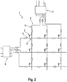
2 einen Faserverbundstoff mit eingebettetem Sensornetzwerk gemäß einem bevorzugten Ausführungsbeispiel der Erfindung.
-
1 a schematic representation of a sensor network of the prior art and -
2 a fiber composite with embedded sensor network according to a preferred embodiment of the invention.
Wird der Verbundwerkstoff
Die Durchgangsprüfung eines Leiterwegs über die Zeilenleiter
BezugszeichenlisteLIST OF REFERENCE NUMBERS
- 11
- Faserverstärkter VerbundwerkstoffFiber reinforced composite material
- 22
- Dioden-MatrixDiode matrix
- 33
- Diodediode
- 44
- Zeilenleiterrow conductor
- 55
- Spaltenleitercolumn conductor
- 66
- Zeilentreiberrow drivers
- 77
- Spaltentreibercolumn driver
- 88th
- Kreuzungspunktintersection
Claims (4)
Priority Applications (7)
| Application Number | Priority Date | Filing Date | Title |
|---|---|---|---|
| DE102016104725.2A DE102016104725B4 (en) | 2016-03-15 | 2016-03-15 | A method of monitoring the structure of a fiber reinforced composite having a sensor array of a plurality of sensors for structure monitoring of the composite |
| PCT/EP2017/056109 WO2017158013A1 (en) | 2016-03-15 | 2017-03-15 | Fiber-reinforced composite material with a sensor assembly for monitoring the structure of the composite material |
| ES17711624T ES2861441T3 (en) | 2016-03-15 | 2017-03-15 | Fiber-reinforced composite material with an array of sensors to monitor the structure of the composite material |
| US16/084,502 US11022505B2 (en) | 2016-03-15 | 2017-03-15 | Fiber-reinforced composite material with a sensor assembly for monitoring the structure of the composite material |
| DK17711624.1T DK3430364T3 (en) | 2016-03-15 | 2017-03-15 | FIBER REINFORCED COMPOSITE MATERIAL WITH SENSOR ARRANGEMENTS FOR STRUCTURAL MONITORING OF THE COMPOSITE MATERIAL |
| EP17711624.1A EP3430364B1 (en) | 2016-03-15 | 2017-03-15 | Fiber-reinforced composite material with a sensor assembly for monitoring the structure of the composite material |
| PL17711624T PL3430364T3 (en) | 2016-03-15 | 2017-03-15 | Fiber-reinforced composite material with a sensor assembly for monitoring the structure of the composite material |
Applications Claiming Priority (1)
| Application Number | Priority Date | Filing Date | Title |
|---|---|---|---|
| DE102016104725.2A DE102016104725B4 (en) | 2016-03-15 | 2016-03-15 | A method of monitoring the structure of a fiber reinforced composite having a sensor array of a plurality of sensors for structure monitoring of the composite |
Publications (2)
| Publication Number | Publication Date |
|---|---|
| DE102016104725A1 DE102016104725A1 (en) | 2017-09-21 |
| DE102016104725B4 true DE102016104725B4 (en) | 2019-01-17 |
Family
ID=58358589
Family Applications (1)
| Application Number | Title | Priority Date | Filing Date |
|---|---|---|---|
| DE102016104725.2A Expired - Fee Related DE102016104725B4 (en) | 2016-03-15 | 2016-03-15 | A method of monitoring the structure of a fiber reinforced composite having a sensor array of a plurality of sensors for structure monitoring of the composite |
Country Status (7)
| Country | Link |
|---|---|
| US (1) | US11022505B2 (en) |
| EP (1) | EP3430364B1 (en) |
| DE (1) | DE102016104725B4 (en) |
| DK (1) | DK3430364T3 (en) |
| ES (1) | ES2861441T3 (en) |
| PL (1) | PL3430364T3 (en) |
| WO (1) | WO2017158013A1 (en) |
Families Citing this family (4)
| Publication number | Priority date | Publication date | Assignee | Title |
|---|---|---|---|---|
| CN110146550B (en) * | 2019-06-13 | 2020-03-13 | 南京航空航天大学 | Method for monitoring oxidation degree of composite material high-temperature part based on electrical impedance imaging |
| CN112285162B (en) * | 2020-10-18 | 2022-04-05 | 西安交通大学 | A system and method for detecting self-sensing properties of metal matrix composites based on continuous carbon core piezoelectric fibers |
| DE102021112608A1 (en) * | 2021-05-14 | 2022-11-17 | Technische Hochschule Köln, Körperschaft des öffentlichen Rechts | Device for monitoring the structure of a surface |
| DE102022109276B4 (en) * | 2022-04-14 | 2025-01-23 | Audi Aktiengesellschaft | Fiber composite component and method for locating a deformation in a fiber composite component |
Citations (6)
| Publication number | Priority date | Publication date | Assignee | Title |
|---|---|---|---|---|
| DE3636074A1 (en) * | 1986-10-23 | 1988-04-28 | Klaus Dreizler | Control and signalling system for detecting water penetrating into buildings |
| WO2005024371A1 (en) | 2003-09-09 | 2005-03-17 | Qinetiq Limited | Sensor and sensor array for monitoring a structure |
| US7546982B2 (en) | 2003-02-05 | 2009-06-16 | Anthony Sneed | Shuttle thermal integrity detection system |
| WO2010004324A1 (en) | 2008-07-08 | 2010-01-14 | Bae Systems Plc | Electrical circuit assemblies and structural components incorporating same |
| US20100119704A1 (en) * | 2007-04-13 | 2010-05-13 | Christopher Douglas Hemmelgarn | Composite self-healing system |
| US20110050258A1 (en) * | 2008-01-17 | 2011-03-03 | Ihi Corporation | Device for detecting space objects |
Family Cites Families (11)
| Publication number | Priority date | Publication date | Assignee | Title |
|---|---|---|---|---|
| US4429413A (en) | 1981-07-30 | 1984-01-31 | Siemens Corporation | Fingerprint sensor |
| US4581527A (en) * | 1983-07-29 | 1986-04-08 | The United States Of America As Represented By The Secretary Of The Navy | Damage assessment system for composite plastic structures using fiber optics |
| US6483931B2 (en) * | 1997-09-11 | 2002-11-19 | Stmicroelectronics, Inc. | Electrostatic discharge protection of a capacitve type fingerprint sensing array |
| LU90233B1 (en) | 1998-04-08 | 1999-10-11 | Iee Sarl | Device for querying several sensor elements in a matrix connection |
| US7067962B2 (en) * | 2000-03-23 | 2006-06-27 | Cross Match Technologies, Inc. | Multiplexer for a piezo ceramic identification device |
| US8161826B1 (en) * | 2009-03-05 | 2012-04-24 | Stryker Corporation | Elastically stretchable fabric force sensor arrays and methods of making |
| TWI397850B (en) * | 2008-05-14 | 2013-06-01 | Ind Tech Res Inst | Sensing apparatus and scanning actuation method thereof |
| DE102008058882A1 (en) | 2008-11-26 | 2010-06-10 | Acentiss Gmbh | Fiber-reinforced plastic structure, has sensor fibers embedded into matrix of plastic surrounding reinforcement fibers, where sensor fibers exhibit defined electrical conductivity which changes during variation of length of sensor fibers |
| US20110086224A1 (en) * | 2009-10-13 | 2011-04-14 | E.I. Du Pont De Nemours And Company | Sheet and Method of Making Sheet for Support Structures and Tires |
| US9651407B2 (en) * | 2011-09-12 | 2017-05-16 | Hewlett-Packard Development Company, L.P. | Configurable sensor arrays |
| EP3071939B1 (en) * | 2013-11-18 | 2019-07-31 | President and Fellows of Harvard College | Printed stretchable strain sensor |
-
2016
- 2016-03-15 DE DE102016104725.2A patent/DE102016104725B4/en not_active Expired - Fee Related
-
2017
- 2017-03-15 DK DK17711624.1T patent/DK3430364T3/en active
- 2017-03-15 ES ES17711624T patent/ES2861441T3/en active Active
- 2017-03-15 PL PL17711624T patent/PL3430364T3/en unknown
- 2017-03-15 EP EP17711624.1A patent/EP3430364B1/en active Active
- 2017-03-15 WO PCT/EP2017/056109 patent/WO2017158013A1/en not_active Ceased
- 2017-03-15 US US16/084,502 patent/US11022505B2/en active Active
Patent Citations (6)
| Publication number | Priority date | Publication date | Assignee | Title |
|---|---|---|---|---|
| DE3636074A1 (en) * | 1986-10-23 | 1988-04-28 | Klaus Dreizler | Control and signalling system for detecting water penetrating into buildings |
| US7546982B2 (en) | 2003-02-05 | 2009-06-16 | Anthony Sneed | Shuttle thermal integrity detection system |
| WO2005024371A1 (en) | 2003-09-09 | 2005-03-17 | Qinetiq Limited | Sensor and sensor array for monitoring a structure |
| US20100119704A1 (en) * | 2007-04-13 | 2010-05-13 | Christopher Douglas Hemmelgarn | Composite self-healing system |
| US20110050258A1 (en) * | 2008-01-17 | 2011-03-03 | Ihi Corporation | Device for detecting space objects |
| WO2010004324A1 (en) | 2008-07-08 | 2010-01-14 | Bae Systems Plc | Electrical circuit assemblies and structural components incorporating same |
Also Published As
| Publication number | Publication date |
|---|---|
| EP3430364A1 (en) | 2019-01-23 |
| US11022505B2 (en) | 2021-06-01 |
| ES2861441T3 (en) | 2021-10-06 |
| WO2017158013A1 (en) | 2017-09-21 |
| PL3430364T3 (en) | 2021-11-08 |
| US20190078947A1 (en) | 2019-03-14 |
| DE102016104725A1 (en) | 2017-09-21 |
| DK3430364T3 (en) | 2021-03-15 |
| EP3430364B1 (en) | 2020-12-09 |
Similar Documents
| Publication | Publication Date | Title |
|---|---|---|
| DE102016104725B4 (en) | A method of monitoring the structure of a fiber reinforced composite having a sensor array of a plurality of sensors for structure monitoring of the composite | |
| DE102012107620B4 (en) | Display panel for a display device and method for detecting defects of signal lines of the display device | |
| EP2603430B1 (en) | Planking panel for a structural component, flow body comprising such a planking panel and device for monitoring material damage on such a planking panel | |
| DE102005018123B4 (en) | Method for evaluating measured values for detecting material fatigue | |
| DE102009031892B4 (en) | Test system for testing a conduit arrangement, use of an adapter in a test system and test apparatus for testing a conduit arrangement and method for producing a conduit arrangement | |
| DE102019218308A1 (en) | Resistor assembly for current sensor and current sensor and method for measuring a battery current | |
| EP3494375B1 (en) | Protection device with a pressure-sensitive sensor for monitoring an industrial plant | |
| DE2937824B1 (en) | Breakage monitoring method and breakable component | |
| DE102005032134A1 (en) | Measuring device for determining and / or monitoring a process variable and method for monitoring the measuring device | |
| WO2019211221A1 (en) | Redundant current-measuring arrangement with detection of interruptions of an electric circuit | |
| DE102016102248A1 (en) | GROUND BREAKING DETECTION | |
| DE102013214302A1 (en) | Deformation device for a vehicle and method for detecting a shortening of a deformation device for a vehicle | |
| DE102021112608A1 (en) | Device for monitoring the structure of a surface | |
| DE102017109398A1 (en) | METHOD AND DEVICE FOR MONITORING A CONNECTION BETWEEN ELECTRICAL EQUIPMENT | |
| DE102018133010A1 (en) | Fiber composite component with an integrated structural condition sensor arrangement | |
| DE202012010194U1 (en) | Arrangement for testing the electrical contact in a carbon fiber component | |
| DE102017207579A1 (en) | Processing a printed circuit board | |
| EP3258230A1 (en) | Sensor skin with temperature sensor system | |
| DE102020120267A1 (en) | Device and method for monitoring a battery system | |
| DE102013212036A1 (en) | Structure section for a vehicle | |
| DE102024209195B4 (en) | Electrical circuit for monitoring the voltage of a battery, method for fault diagnosis of measuring connections and corresponding control unit | |
| DE19625586C1 (en) | Pipe monitoring circuit for heat energy transport medium to domestic users | |
| DE102016217539A1 (en) | A method of investigating rupture or crack propagation in the wall of a pressure vessel | |
| EP4726348A1 (en) | Method for monitoring the function of a pressure measuring device and pressure measuring device | |
| DE602005003583T2 (en) | DEVICE AND METHOD FOR TESTING AT LEAST ONE CONDUCTIVE CONNECTION FOR FORMING AN ELECTRICAL CONNECTION BETWEEN AN ELECTRICAL COMPONENT AND A CONDUCTOR PLATE |
Legal Events
| Date | Code | Title | Description |
|---|---|---|---|
| R012 | Request for examination validly filed | ||
| R083 | Amendment of/additions to inventor(s) | ||
| R163 | Identified publications notified | ||
| R016 | Response to examination communication | ||
| R018 | Grant decision by examination section/examining division | ||
| R020 | Patent grant now final | ||
| R119 | Application deemed withdrawn, or ip right lapsed, due to non-payment of renewal fee |