DE102016104439A1 - An imaging device, an optical observation device, and a method of capturing images - Google Patents

An imaging device, an optical observation device, and a method of capturing images Download PDF

Info

Publication number
DE102016104439A1
DE102016104439A1 DE102016104439.3A DE102016104439A DE102016104439A1 DE 102016104439 A1 DE102016104439 A1 DE 102016104439A1 DE 102016104439 A DE102016104439 A DE 102016104439A DE 102016104439 A1 DE102016104439 A1 DE 102016104439A1
Authority
DE
Germany
Prior art keywords
light
filter
light source
observation object
image
Prior art date
Legal status (The legal status is an assumption and is not a legal conclusion. Google has not performed a legal analysis and makes no representation as to the accuracy of the status listed.)
Withdrawn
Application number
DE102016104439.3A
Other languages
German (de)
Inventor
Roland Guckler
Current Assignee (The listed assignees may be inaccurate. Google has not performed a legal analysis and makes no representation or warranty as to the accuracy of the list.)
Carl Zeiss Meditec AG
Original Assignee
Carl Zeiss Meditec AG
Priority date (The priority date is an assumption and is not a legal conclusion. Google has not performed a legal analysis and makes no representation as to the accuracy of the date listed.)
Filing date
Publication date
Application filed by Carl Zeiss Meditec AG filed Critical Carl Zeiss Meditec AG
Priority to PCT/EP2016/070023 priority Critical patent/WO2017036893A1/en
Publication of DE102016104439A1 publication Critical patent/DE102016104439A1/en
Withdrawn legal-status Critical Current

Links

Images

Classifications

    • AHUMAN NECESSITIES
    • A61MEDICAL OR VETERINARY SCIENCE; HYGIENE
    • A61BDIAGNOSIS; SURGERY; IDENTIFICATION
    • A61B1/00Instruments for performing medical examinations of the interior of cavities or tubes of the body by visual or photographical inspection, e.g. endoscopes; Illuminating arrangements therefor
    • A61B1/04Instruments for performing medical examinations of the interior of cavities or tubes of the body by visual or photographical inspection, e.g. endoscopes; Illuminating arrangements therefor combined with photographic or television appliances
    • A61B1/043Instruments for performing medical examinations of the interior of cavities or tubes of the body by visual or photographical inspection, e.g. endoscopes; Illuminating arrangements therefor combined with photographic or television appliances for fluorescence imaging
    • GPHYSICS
    • G02OPTICS
    • G02BOPTICAL ELEMENTS, SYSTEMS OR APPARATUS
    • G02B21/00Microscopes
    • G02B21/0004Microscopes specially adapted for specific applications
    • G02B21/0012Surgical microscopes
    • GPHYSICS
    • G02OPTICS
    • G02BOPTICAL ELEMENTS, SYSTEMS OR APPARATUS
    • G02B21/00Microscopes
    • G02B21/0004Microscopes specially adapted for specific applications
    • G02B21/002Scanning microscopes
    • G02B21/0024Confocal scanning microscopes (CSOMs) or confocal "macroscopes"; Accessories which are not restricted to use with CSOMs, e.g. sample holders
    • G02B21/0052Optical details of the image generation
    • G02B21/0076Optical details of the image generation arrangements using fluorescence or luminescence
    • GPHYSICS
    • G02OPTICS
    • G02BOPTICAL ELEMENTS, SYSTEMS OR APPARATUS
    • G02B21/00Microscopes
    • G02B21/06Means for illuminating specimens
    • GPHYSICS
    • G02OPTICS
    • G02BOPTICAL ELEMENTS, SYSTEMS OR APPARATUS
    • G02B5/00Optical elements other than lenses
    • G02B5/20Filters
    • G02B5/208Filters for use with infrared or ultraviolet radiation, e.g. for separating visible light from infrared and/or ultraviolet radiation

Landscapes

  • Physics & Mathematics (AREA)
  • Health & Medical Sciences (AREA)
  • Optics & Photonics (AREA)
  • General Physics & Mathematics (AREA)
  • Life Sciences & Earth Sciences (AREA)
  • Analytical Chemistry (AREA)
  • Chemical & Material Sciences (AREA)
  • Surgery (AREA)
  • General Health & Medical Sciences (AREA)
  • Pathology (AREA)
  • Public Health (AREA)
  • Heart & Thoracic Surgery (AREA)
  • Medical Informatics (AREA)
  • Molecular Biology (AREA)
  • Animal Behavior & Ethology (AREA)
  • Engineering & Computer Science (AREA)
  • Biomedical Technology (AREA)
  • Veterinary Medicine (AREA)
  • Radiology & Medical Imaging (AREA)
  • Nuclear Medicine, Radiotherapy & Molecular Imaging (AREA)
  • Biophysics (AREA)
  • Toxicology (AREA)
  • Microscoopes, Condenser (AREA)
  • Investigating, Analyzing Materials By Fluorescence Or Luminescence (AREA)

Abstract

Es wird eine Bildaufnahmeanordnung (1) zur Verfügung gestellt. Diese ist ausgestattet mit – einer Lichtquellenanordnung (13) zur Emission von Licht, welches sichtbares Licht (11) und Anregungslicht (10) zum Anregen einer Infrarotemission in einem Beobachtungsobjekt (4) umfasst, – einer Aufnahmeeinrichtung (3) mit einem Bildsensor zur Aufnahme eines Bildes von einem mit dem Licht der Lichtquellenanordnung (13) bestrahlten Beobachtungsobjekt (4), und – einen zwischen dem Beobachtungsobjekt (4) und dem Bildsensor der Aufnahmeeinrichtung (3) angeordneten Aufnahmefilter (9), dessen Transmissionscharakteristik derart ausgestaltet ist, dass sie vom Beobachtungsobjekt (4) reflektiertes sichtbares Licht (16) und vom Beobachtungsobjekt (4) emittiertes Infrarotlicht (12) passieren lässt, vom Beobachtungsobjekt (4) reflektiertes Anregungslicht (10) jedoch blockiert. Die Lichtquellenanordnung (13) ist derart einstellbar ist, dass sie entweder nur sichtbares Licht (11) oder nur Anregungslicht (10) in Richtung auf das Beobachtungsobjekt (4) aussendet.An image pickup device (1) is provided. This is equipped with - a light source arrangement (13) for emitting light, which comprises visible light (11) and excitation light (10) for exciting an infrared emission in an observation object (4), - a recording device (3) with an image sensor for receiving a Image of an observation object (4) irradiated with the light of the light source arrangement (13), and - a recording filter (9) arranged between the observation object (4) and the image sensor of the recording device (3) whose transmission characteristic is designed such that it is from the observation object (4) allows reflected visible light (16) and infrared light (12) emitted by the observation object (4) to pass through, but that the excitation light (10) reflected by the observation object (4) is blocked. The light source arrangement (13) is adjustable such that it emits either only visible light (11) or only excitation light (10) in the direction of the observation object (4).

Description

Die Erfindung betrifft eine Bildaufnahmeanordnung sowie ein optisches Beobachtungsgerät mit einer Bildaufnahmeanordnung. Daneben betrifft die Erfindung Verfahren zum Aufnehmen von Bildern im sichtbaren Spektralbereich und von Infrarotbildern von einem Beobachtungsobjekt. The invention relates to an image pickup device and an optical observation device with an image pickup device. In addition, the invention relates to methods for capturing images in the visible spectral range and infrared images of an observation object.

Im medizinischen Bereich werden häufig Kontrastmittel/Indikatorsubstanzen eingesetzt, um Vorgänge und Zustände im Körper sichtbar zu machen, die durch den Einsatz von sichtbarem Licht (Weißlicht) allein nicht oder nur unzureichend erkennbar sind. Als Indikatorsubstanzen kommen insbesondere fluoreszierende Farbstoffe wie zum Beispiel Indocyaningrün (ICG) in Frage. Wird Indocyaningrün mit Licht im nahinfraroten Spektralbereich von etwa 600 nm bis etwa 900 nm (Absorptionsspektrum) bestrahlt, fluoresziert Indocyaningrün, indem es Licht im nahinfraroten Spektralbereich von etwa 750 nm bis etwa 950 nm (Fluoreszenzspektrum) abgibt. Das von Indocyaningrün emittierte Licht kann von einer nahinfrarotlichtempfindlichen Kamera detektiert werden. Da Indocyaningrün die Fähigkeit besitzt, sich an Plasmaproteine zu binden, lässt sich beispielsweise durch die intravaskuläre Verabreichung von Indocyaningrün in den Blutkreislauf die Perfusion von Geweben und Organen mit Hilfe von Nah-Infrarotlichtaufnahmen beurteilen (siehe beispielsweise https://de.wikipedia.org/wiki/Indocyaningrün ). In the medical field contrast agent / indicator substances are often used to visualize processes and conditions in the body, which are not or only insufficiently recognizable by the use of visible light (white light) alone. Suitable indicator substances are, in particular, fluorescent dyes, such as, for example, indocyanine green (ICG). When indocyanine green is irradiated with light in the near-infrared spectral range of about 600 nm to about 900 nm (absorption spectrum), indocyanine green fluoresces by emitting light in the near-infrared spectral range of about 750 nm to about 950 nm (fluorescence spectrum). The light emitted by indocyanine green light can be detected by a near infrared light sensitive camera. For example, as indocyanine green has the ability to bind to plasma proteins, the intravascular administration of indocyanine green into the bloodstream allows the perfusion of tissues and organs to be assessed by near infrared light imaging (see, for example, US Pat https://de.wikipedia.org/wiki/Indocyaningrün ).

Existierende Operationsmikroskope weisen jedoch häufig nur eine Kamera mit einem Infrarotsperrfilter auf, sodass nur sichtbares Licht bzw. Weißlicht auf die Kamera treffen kann. Für Aufnahmen von fluoreszierendem Indocyaningrün müsste daher entweder eine zusätzliche Kamera mit einem Infrarotlicht durchlassenden Filter oder eine Kamera ohne Infrarotsperrfilter mit einem vorgelagerten Filterrad mit einem Infrarotlicht durchlassenden und einem Infrarotlicht blockierenden Filter nachgerüstet werden. Dies hätte allerdings zur Folge, dass entweder zusätzlich zum Operationsmikroskop ein weiteres Gerät verwendet werden müsste, nämlich eine zusätzliche Kamera mit einem Infrarotlicht durchlassenden Filter, oder dass ein bestehendes Operationsmikroskop umgebaut und mit einem größeren Kopf/Bildaufnahmebereich ausgestattet werden müsste, in welchem die zusätzliche Kamera oder das der Kamera vorgelagerte Filterrad Platz finden. However, existing surgical microscopes often have only one camera with an infrared blocking filter, so that only visible light or white light can hit the camera. Therefore, for capturing fluorescent indocyanine green, either an additional camera with an infrared-transmitting filter or a camera without an infrared-blocking filter would have to be retrofitted with an upstream filter wheel with an infrared light-transmitting filter and an infrared-blocking filter. However, this would mean that either in addition to the surgical microscope another device would have to be used, namely an additional camera with a filter passing through infrared light, or that an existing surgical microscope would have to be rebuilt and equipped with a larger head / image pickup area, in which the additional camera or find the filter wheel upstream of the camera.

Aus der Patentanmeldung US 2008/0251694 A1 ist eine Bildaufnahmevorrichtung für den medizinischen Bereich bekannt, mit der ein Bild aufgenommen werden kann, in dem eine Abbildung im sichtbaren Spektralbereich mit einer Abbildung im infraroten Spektralbereich kombiniert ist. Die Bildaufnahmevorrichtung weist eine erste Lichtquelle für sichtbares Licht und eine zweite Lichtquelle für Licht zum Anregen einer im Infraroten fluoreszierenden Substanz auf. Licht aus beiden Lichtquellen trifft auf das zu untersuchende, mit einer fluoreszierenden Substanz versehene Objekt. Zur Aufnahme eines Bildes Objekts ist ein CCD-Lichtsensor vorhanden, dem ein Filter vorgeschaltet ist, welcher das Licht zum Anregen der Infrarotlicht fluoreszierenden Substanz blockiert und von dem Objekt emittiertes Licht im sichtbaren Wellenlängenbereich und im Infrarotlichtbereich passieren lässt. Um im aufgenommenen Bild das vom Objekt emittierte Infrarotlicht gegenüber dem emittierten sichtbaren Licht hervorzuheben, weist der Filter im sichtbaren Spektralbereich eine erheblich geringere Transmission als im nahinfraroten Spektralbereich auf. Dadurch wird ein zusammengesetztes Bild erhalten, in dem ein ausgewogenes Verhältnis zwischen der Abbildung im sichtbaren Spektralbereich und der Abbildung im nahen infraroten Spektralbereich vorliegt. From the patent application US 2008/0251694 A1 For example, a medical imaging device is known that can capture an image combining a visible-spectral image with an infrared-spectral image. The image pickup device has a first visible light source and a second light source for exciting a fluorescent substance in the infrared. Light from both light sources strikes the object to be examined, provided with a fluorescent substance. To record an image object, a CCD light sensor is present, preceded by a filter which blocks the light for exciting the infrared light fluorescent substance and allows light emitted by the object to pass in the visible wavelength range and in the infrared light range. In order to emphasize the infrared light emitted by the object in the recorded image with respect to the emitted visible light, the filter has a significantly lower transmission in the visible spectral range than in the near-infrared spectral range. This results in a composite image in which there is a good balance between the image in the visible spectral region and the image in the near infrared spectral region.

Es ist eine erste Aufgabe der Erfindung, eine Bildaufnahmeanordnung bereitzustellen, mit der in vorteilhafter Weise von einem Beobachtungsobjekt wahlweise ein Infrarotbild oder ein Bild im sichtbaren Spektralbereich aufgenommen werden kann. Es ist eine zweite Aufgabe der Erfindung, ein optisches Beobachtungsgerät bereitzustellen, mit dem in vorteilhafter Weise von einem Beobachtungsobjekt wahlweise ein Infrarotbild oder ein Bild im sichtbaren Spektralbereich aufgenommen werden kann. Eine dritte Aufgabe der Erfindung ist es, ein vorteilhaftes Verfahren zum Aufnehmen von Bildern im sichtbaren Spektralbereich und von Infrarotbildern von einem Beobachtungsobjekt zur Verfügung zu stellen. It is a first object of the invention to provide an image pickup arrangement with which, advantageously, an infrared image or an image in the visible spectral range can be recorded by an observation object. It is a second object of the invention to provide an optical observation apparatus with which advantageously an infrared image or an image in the visible spectral range can be recorded by an observation object. A third object of the invention is to provide an advantageous method for capturing images in the visible spectral range and of infrared images from an observation object.

Die erste Aufgabe wird durch eine Bildaufnahmeanordnung mit den Merkmalen des Anspruchs 1 gelöst, die zweite Aufgabe durch ein optisches Beobachtungsgerät mit den Merkmalen des Anspruchs 11. Die dritte Aufgabe wird durch ein Verfahren zum Aufnehmen von Bildern im sichtbaren Spektralbereich und von Infrarotbildern nach Anspruch 14 gelöst. Die abhängigen Ansprüche enthalten vorteilhafte Ausgestaltungen der Erfindung. The first object is achieved by an image recording device having the features of claim 1, the second object by an optical observation device having the features of claim 11. The third object is achieved by a method for capturing images in the visible spectral range and infrared images according to claim 14 , The dependent claims contain advantageous embodiments of the invention.

Eine erfindungsgemäße Bildaufnahmeanordnung umfasst eine Lichtquellenanordnung zur Emission von Licht, welches sichtbares Licht und Anregungslicht zum Anregen einer Infrarotemission in einem Beobachtungsobjekt umfasst. Das sichtbare Licht kann hierbei insbesondere Weißlicht sein. An imaging arrangement according to the invention comprises a light source arrangement for emitting light, which comprises visible light and excitation light for exciting an infrared emission in an observation object. The visible light here may be white light in particular.

Weiterhin umfasst die erfindungsgemäße Bildaufnahmeanordnung eine Aufnahmeeinrichtung mit einem Bildsensor zur Aufnahme eines Bildes von einem mit dem Licht der Lichtquellenanordnung bestrahlten Beobachtungsobjekt sowie einen zwischen dem Beobachtungsobjekt und der Aufnahmeeinrichtung angeordneten oder anzuordnenden Aufnahmefilter, dessen Transmissionscharakteristik derart ausgestaltet ist, dass sie vom Beobachtungsobjekt reflektiertes sichtbares Licht und vom Beobachtungsobjekt emittiertes Infrarotlicht passieren lässt, vom Beobachtungsobjekt reflektiertes Anregungslicht jedoch blockiert. Insbesondere kann die Transmissionscharakteristik des Aufnahmefilters derart gewählt sein, dass er Licht in einem Wellenlängenbereich von 400 nm bis 700 nm sowie in einem Wellenlängenbereich von 800 nm bis 950 nm passieren lässt und Licht in einem Wellenlängenbereich von 700 nm bis 800 nm blockiert. Furthermore, the image recording arrangement according to the invention comprises a recording device with an image sensor for recording an image of an observation object irradiated with the light of the light source arrangement and a recording filter arranged or to be arranged between the observation object and the recording device, the transmission characteristic thereof is designed such that it allows visible light reflected by the observation object and infrared light emitted by the observation object to pass through, but that the excitation light reflected by the observation object is blocked. In particular, the transmission characteristic of the recording filter can be chosen such that it allows light to pass in a wavelength range from 400 nm to 700 nm and in a wavelength range from 800 nm to 950 nm and blocks light in a wavelength range from 700 nm to 800 nm.

Darüber hinaus ist die Lichtquellenanordnung derart einstellbar, dass sie entweder nur sichtbares Licht oder nur Anregungslicht in Richtung auf das Beobachtungsobjekt aussendet. In addition, the light source arrangement is adjustable so that it emits either only visible light or only excitation light in the direction of the observation object.

In einer ersten Variante umfasst die Lichtquellenanordnung eine sowohl sichtbares Licht als auch Anregungslicht emittierende Lichtquelle und einen Filterwechsler, der zwischen der Lichtquelle und dem Beobachtungsobjekt angeordnet oder anzuordnen ist und der wenigstens mit einem ersten Filter und einem zweiten Filter ausgestattet ist. Der erste Filter weist eine erste Filtercharakteristik auf, die nur das sichtbare Licht passieren lässt, der zweite Filter eine zweite Filtercharakteristik, die nur das Anregungslicht passieren lässt. Hierbei ist es vorteilhaft, wenn sich das Spektrum des von der Lichtquelle ausgesandten Lichtes wenigstens über den Spektralbereich von 400 nm bis 800 nm erstreckt. Mittels des Filterwechslers kann die Lichtquellenanordnung somit derart eingestellt werden, dass sie entweder nur sichtbares Licht oder nur Anregungslicht in Richtung auf das Beobachtungsobjekt aussendet. Als Lichtquelle kann in der Lichtquellenanordnung hierbei beispielsweise eine Xenonlampe oder eine Halogenglühlampe zum Einsatz kommen. Die erste Filtercharakteristik kann insbesondere derart gewählt sein, dass der erste Filter nur Licht in einem Wellenlängenbereich von 400 nm bis 700 nm passieren lässt, und die zweite Filtercharakteristik kann insbesondere derart gewählt sein, dass der zweite Filter nur Licht in einem Wellenlängenbereich von 700 nm bis 800 nm passieren lässt. Der Filterwechsler kann bspw. als Filterrad, als Schieber, als verschwenkbarer Filterträger, etc. ausgebildet sein. Andere Ausgestaltungen sind jedoch auch möglich. In a first variant, the light source arrangement comprises a light source emitting both visible light and excitation light and a filter changer which is arranged or to be arranged between the light source and the observation object and which is equipped at least with a first filter and a second filter. The first filter has a first filter characteristic which allows only the visible light to pass, the second filter a second filter characteristic which allows only the excitation light to pass. In this case, it is advantageous if the spectrum of the light emitted by the light source extends at least over the spectral range from 400 nm to 800 nm. By means of the filter changer, the light source arrangement can thus be set such that it emits either only visible light or only excitation light in the direction of the observation object. As the light source in this case, for example, a xenon lamp or a halogen incandescent lamp can be used in the light source arrangement. The first filter characteristic may in particular be selected such that the first filter only allows light to pass in a wavelength range of 400 nm to 700 nm, and the second filter characteristic may be chosen such that the second filter only light in a wavelength range of 700 nm 800 nm happen. The filter changer can be designed, for example, as a filter wheel, as a slide, as a pivotable filter carrier, etc. However, other embodiments are also possible.

In einer zweiten Variante umfasst die Lichtquellenanordnung eine nur sichtbares Licht emittierende erste Lichtquelle, eine nur Anregungslicht emittierende Lichtquelle und eine Schalteinrichtung, wobei die Schalteinrichtung es ermöglicht, die Lichtquellenanordnung entweder nur mit der ersten Lichtquelle oder nur mit der zweiten Lichtquelle zu betreiben. Mittels der Schalteinrichtung kann die Lichtquellenanordnung somit derart eingestellt werden, dass sie entweder nur sichtbares Licht oder nur Anregungslicht in Richtung auf das Beobachtungsobjekt aussendet. Die erste Lichtquelle kann hierbei insbesondere derart ausgestaltet sein, dass sie nur Licht in einem Wellenlängenbereich von 400 nm bis 700 nm emittiert, und die zweite Lichtquelle kann insbesondere derart ausgestaltet sein, dass sie nur Licht in einem Wellenlängenbereich von 700 nm bis 800 nm emittiert. Als erste Lichtquelle eignen sich bspw. neutralweißes oder tagweißes Licht emittierende Lampen wie etwa LED-Lampen oder Metalldampflampen, die mit geringer Emission im Spektralbereich über 700 nm, also im nahen Infrarot, erhältlich sind. Als zweite Lichtquelle kann bspw. eine Anregungslicht emittierende LED oder eine Anregungslicht emittierende Laserdiode Verwendung finden. In a second variant, the light source arrangement comprises an only visible light-emitting first light source, a light source only excitation light and a switching device, wherein the switching device makes it possible to operate the light source arrangement either only with the first light source or only with the second light source. By means of the switching device, the light source arrangement can thus be adjusted such that it emits either only visible light or only excitation light in the direction of the observation object. In this case, the first light source can in particular be configured such that it emits only light in a wavelength range from 400 nm to 700 nm, and the second light source can be designed in particular such that it emits only light in a wavelength range from 700 nm to 800 nm. For example, neutral-white or day-white light-emitting lamps such as LED lamps or metal halide lamps which are obtainable with low emission in the spectral range above 700 nm, ie in the near infrared, are suitable as the first light source. For example, an excitation light-emitting LED or an excitation light-emitting laser diode can be used as the second light source.

Als Aufnahmeeinrichtung kann im Rahmen der erfindungsgemäßen Bildaufnahmeanordnung bspw. auch eine Standardkamera, bei der der standardmäßig eingebaute Infrarotsperrfilter durch den beschriebenen Aufnahmefilter ersetzt ist, Verwendung finden. As a recording device can, for example, in the context of the image recording device according to the invention, a standard camera in which the standard built-infrared filter is replaced by the recording filter described, use.

Mit der erfindungsgemäßen Bildaufnahmeanordnung lässt sich das erfindungsgemäße Verfahren zum Aufnehmen von Bildern von einem Beobachtungsobjekt im sichtbaren Spektralbereich und von Infrarotbildern von dem Beobachtungsobjekt durchführen. In diesem Verfahren wird das Beobachtungsobjekt ausschließlich mit sichtbarem Licht, d.h. Licht im sichtbaren Spektralbereich, beleuchtet, wenn ein Bild im sichtbaren Spektralbereich aufgenommen werden soll, und ausschließlich mit einem Anregungslicht zum Anregen einer Infrarotemission in dem Beobachtungsobjekt, wenn ein Bild im infraroten Spektralbereich aufgenommen werden soll. Als Lichtquelle kann hierbei bspw. eine Lichtquelle zur Emission von Licht, welches das sichtbare Licht und das Anregungslicht zum Anregen einer Infrarotemission in einem Beobachtungsobjekt emittiert, Verwendung finden. Zum Bestrahlen des Beobachtungsobjekts ausschließlich mit sichtbarem Licht kann dann der erste Filter zwischen der Lichtquelle und dem Beobachtungsobjekt angeordnet werden, der nur das sichtbare Licht passieren lässt, und zum Bestrahlen des Beobachtungsobjekts ausschließlich mit Anregungslicht der zweite Filter, der nur das Anregungslicht passieren lässt. Alternativ können eine nur sichtbares Licht emittierende erste Lichtquelle und eine nur Anregungslicht emittierende Lichtquelle Verwendung finden. In diesem Fall wird zum Beleuchten des Beobachtungsobjekts ausschließlich mit dem sichtbaren Licht nur die erste Lichtquelle betrieben und zum Beleuchten des Beobachtungsobjekts ausschließlich mit dem Anregungslicht nur die zweite Lichtquelle. Das zum Bildsensor der Aufnahmeeinrichtung gelangende Licht wird vor Erreichen des Bildsensors mit einem Aufnahmefilter, dessen Transmissionscharakteristik derart ausgestaltet ist, dass er vom Beobachtungsobjekt reflektiertes sichtbares Licht sowie vom Beobachtungsobjekt emittiertes Infrarotlicht passieren lässt, vom Beobachtungsobjekt reflektiertes Anregungslicht jedoch blockiert, gefiltert. With the image recording arrangement according to the invention, the method according to the invention for taking pictures of an observation object in the visible spectral range and of infrared images of the observation object can be carried out. In this method, the observation object is illuminated exclusively with visible light, ie, light in the visible spectral range, when an image is to be recorded in the visible spectral range, and exclusively with excitation light for exciting an infrared emission in the observation subject when an image is acquired in the infrared spectral range should. For example, a light source for emitting light which emits the visible light and the excitation light for exciting an infrared emission in an observation object can be used as the light source. For irradiating the observation object exclusively with visible light, the first filter between the light source and the observation object can then be arranged, which allows only the visible light to pass, and for irradiating the observation object exclusively with excitation light, the second filter, which allows only the excitation light to pass. Alternatively, an only visible light-emitting first light source and an excitation light-emitting light source may be used. In this case, only the first light source is operated for illuminating the observation object exclusively with the visible light, and only the second light source for illuminating the observation object exclusively with the excitation light. The reaching to the image sensor of the recording device light is before reaching the image sensor with a recording filter, the transmission characteristic is designed such that it reflected light from the object to be observed and emitted by the observation object Infrared light passes, however, reflected by the observation object excitation light blocked, filtered.

Dadurch, dass bei der erfindungsgemäßen Bildaufnahmeanordnung bzw. bei dem erfindungsgemäßen Verfahren das sichtbare Licht bzw. das Anregungslicht auf Seiten der Lichtquelle von Infrarotlicht außerhalb des Spektralbereiches des Anregungslichtes getrennt wird, und dadurch, dass das Anregungslicht durch den Aufnahmefilter blockiert wird, wird es möglich, zum Aufnehmen von Fluoreszenzbildern im infraroten Spektralbereich und zum Aufnehmen von Bildern im sichtbaren Spektralbereich auf Seiten des Bildsensors der Aufnahmeeinrichtung lediglich einen einzigen Filter zu verwenden, so dass ein Filterrad vor der Kamera oder die Verwendung zweier Kameras nicht nötig ist. Die erfindungsgemäße Bildaufnahmeanordnung benötigt daher im Bereich der Aufnahmeeinrichtung nur wenig Bauraum. Dies ist insbesondere dann vorteilhaft, wenn die Bildaufnahmeanordnung bspw. in einem Operationsmikroskop oder einem Endoskop zum Einsatz kommen soll, wo eine zweite Kamera oder ein Filterwechsler vor der Kamera zusätzliches Volumen im Bereich des Beobachtungsstrahlengangs des Operationsmikroskops benötigen würde und so zu Einschränkungen der Bewegungsfreiheit des behandelnden Arztes führen könnte. Das Anordnen eines Filterwechslers zwischen der Lichtquelle und dem Operationssitus ist dagegen in der Regel wenig störend, da die Lichtquelle – und somit auch der Filterwechsler – für gewöhnlich in größerer Entfernung von dem Operationssitus angeordnet werden kann als die Beobachtungsoptik des Operationsmikroskops oder des Endoskops. The fact that in the image recording arrangement according to the invention or in the method according to the invention the visible light or the excitation light on the side of the light source is separated from infrared light outside the spectral range of the excitation light, and in that the excitation light is blocked by the recording filter, it becomes possible for recording fluorescence images in the infrared spectral range and for recording images in the visible spectral range on the side of the image sensor of the recording device to use only a single filter, so that a filter wheel in front of the camera or the use of two cameras is not necessary. The image recording device according to the invention therefore requires only little space in the region of the receiving device. This is particularly advantageous if the image recording device is to be used, for example, in a surgical microscope or an endoscope, where a second camera or a filter changer in front of the camera would require additional volume in the area of the observation beam path of the surgical microscope and thus to restrictions on the freedom of movement of the patient Doctor could lead. On the other hand, arranging a filter changer between the light source and the surgical site is generally less troublesome because the light source - and thus also the filter changer - can usually be arranged at a greater distance from the surgical site than the observation optics of the surgical microscope or the endoscope.

In der erfindungsgemäßen Bildaufnahmeanordnung kann die Transmissionscharakteristik des Aufnahmefilters derart gewählt sein, dass sich die Tranmission für das vom Beobachtungsobjekt reflektierte sichtbare Licht nicht mehr als 10%, insbesondere nicht mehr als 5%, von der Transmission für das vom Beobachtungsobjekt emittierte Infrarotlicht unterscheidet. Dabei kann die Transmissionscharakteristik des Aufnahmefilters derart gewählt sein, dass die Transmission für das vom Beobachtungsobjekt reflektierte sichtbare Licht und die Transmission für das vom Beobachtungsobjekt emittierte Infrarotlicht jeweils mindestens 80% und vorzugsweise jeweils mindestens 90% betragen. Auf diese Weise kann bei einem insgesamt hohen Transmissionsgrad von mindestens 80%, vorzugsweise von mindestens 90%, eine hohe Empfindlichkeit der Aufnahmeeinrichtung sowohl im sichtbaren Spektralbereich als auch im infraroten Spektralbereich realisiert werden. In the image recording arrangement according to the invention, the transmission characteristic of the recording filter can be selected such that the transmission for the visible light reflected from the observation object does not differ from the transmission for the infrared light emitted by the observation object by more than 10%, in particular not more than 5%. In this case, the transmission characteristic of the recording filter can be selected such that the transmission for the visible light reflected from the observation object and the transmission for the infrared light emitted by the observation object are in each case at least 80% and preferably in each case at least 90%. In this way, with a total high degree of transmission of at least 80%, preferably of at least 90%, a high sensitivity of the recording device can be realized both in the visible spectral range and in the infrared spectral range.

Ein erfindungsgemäßes optisches Beobachtungsgerät, das insbesondere als Operationsmikroskop oder als Endoskop ausgestaltet sein kann, ist mit einer erfindungsgemäßen Bildaufnahmeanordnung ausgestattet. In einer speziellen Ausgestaltung kann das optische Beobachtungsgerät eine Abbildungsoptik umfassen, die wenigstens ein Bild des Beobachtungsobjekts generiert, und in der am Ort des Bildes des Beobachtungsobjekts ein Bildsensor angeordnet ist, wobei die Abbildungsoptik dann zusammen mit dem Bildsensor die Aufnahmeeinrichtung bildet. An optical observation device according to the invention, which can be configured in particular as a surgical microscope or as an endoscope, is equipped with an image recording device according to the invention. In a specific embodiment, the optical observation device may comprise imaging optics which generate at least one image of the observation object and in which an image sensor is arranged at the location of the image of the observation object, the imaging optics then forming the recording device together with the image sensor.

Weitere Merkmale, Eigenschaften und Vorteile der vorliegenden Erfindung können sich aus der nachfolgenden Beschreibung unter Bezugnahme auf die beiliegenden Figuren ergeben. Other features, characteristics and advantages of the present invention may become apparent from the following description with reference to the accompanying drawings.

1 zeigt eine schematische Darstellung eines ersten Ausführungsbeispiels der erfindungsgemäßen Bildaufnahmeanordnung bei der Aufnahme eines Infrarotbildes. 1 shows a schematic representation of a first embodiment of the image pickup device according to the invention in the recording of an infrared image.

2 zeigt eine schematische Darstellung des ersten Ausführungsbeispiels bei der Aufnahme eines Farbbildes. 2 shows a schematic representation of the first embodiment in the recording of a color image.

3 zeigt die Transmissionscharakteristika des im ersten Ausführungsbeispiel verwendeten ersten Filters und des im ersten Ausführungsbeispiel verwendeten zweiten Filters (oben) sowie des Aufnahmefilters (unten), wobei die Transmission in Abhängigkeit von der Wellenlänge dargestellt ist. 3 shows the transmission characteristics of the first filter used in the first embodiment and the second filter used in the first embodiment (top) and the receiving filter (bottom), wherein the transmission is shown as a function of the wavelength.

4 zeigt eine schematische Darstellung eines zweiten Ausführungsbeispiels der erfindungsgemäßen Bildaufnahmeanordnung bei der Aufnahme eines Infrarotbildes. 4 shows a schematic representation of a second embodiment of the image pickup device according to the invention in the recording of an infrared image.

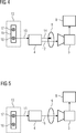
5 zeigt eine schematische Darstellung des zweiten Ausführungsbeispiels bei der Aufnahme eines Farbbildes. 5 shows a schematic representation of the second embodiment in the recording of a color image.

6 zeigt ein Beispiel für den grundsätzlichen Aufbau eines Operationsmikroskops mit Unendlichstrahlengang in einer schematischen Darstellung. 6 shows an example of the basic structure of a surgical microscope with infinity beam in a schematic representation.

In den Figuren bezeichnen gleiche Bezugszeichen gleiche oder gleich wirkende Komponenten. In the figures, like reference numerals designate like or equivalent components.

Die 1 und 2 zeigen eine erfindungsgemäße Bildaufnahmeanordnung 1 mit einer Lichtquellenanordnung 13 und einer Kamera 3 als Aufnahmeeinrichtung. Die Lichtquellenanordnung 13 des Ausführungsbeispiels umfasst eine Lichtquelle 2, die im vorliegenden Ausführungsbeispiel eine Xenonlampe ist. Als solche ist sie eine Breitbandlichtquelle, die im Betrieb sowohl Weißlicht 11 im sichtbaren Spektralbereich als auch Licht mit einem Spektrum zum Anregen einer Infrarotfluoreszenz in einem Beobachtungsobjekt 4, im Folgenden Anregungslicht 10 genannt, emittiert. Das Spektrum der Xenonlampe 2 umfasst dabei einen Spektralbereich von 400 nm bis 900 nm, wobei das Weißlicht 11 dem Spektralbereich von 400 nm bis 700 nm und das Anregungslicht 10 im vorliegenden Ausführungsbeispiel dem Wellenlängenbereich von 700 nm bis 900 nm entsprechen. Damit ist die Lichtquelle 2 insbesondere zum Anregen der Fluoreszenz in einem Indocyaningrün enthaltenden Beobachtungsobjekt 4 geeignet. Indocyaningrün wird im medizinischen Anwendungsbereich häufig als Kontrastmittel eingesetzt, um durch sichtbares Licht nicht erkennbare Gewebe-/Gefäßzustände sichtbar zu machen. Indocyaningrün absorbiert Licht im Wellenlängenbereich von 600 nm bis 900 nm und emittiert Fluoreszenzstrahlung von 750 nm bis 950 nm, also in einem Ausschnitt des nahinfraroten Wellenlängenbereiches. Bei einer Anregung im Wellenlängenbereich von 700 nm bis 800 nm kann daher eine Fluoreszenz mit Indocyaningrün versehener Objektbereiche im Wellenlängenbereich über 800 nm beobachtet werden. The 1 and 2 show an image pickup arrangement according to the invention 1 with a light source arrangement 13 and a camera 3 as a recording device. The light source arrangement 13 of the embodiment comprises a light source 2 which is a xenon lamp in the present embodiment. As such, it is a broadband light source that in operation both white light 11 in the visible spectral region as well as light with a spectrum for exciting an infrared fluorescence in an observation object 4 , in the following excitation light 10 called, emitted. The spectrum of the xenon lamp 2 covers a spectral range from 400 nm to 900 nm, the white light 11 the Spectral range from 400 nm to 700 nm and the excitation light 10 in the present embodiment correspond to the wavelength range of 700 nm to 900 nm. This is the light source 2 in particular for exciting the fluorescence in an observation object containing indocyanine green 4 suitable. Indocyanine green is often used in the medical field as a contrast agent to make visible by visible light unrecognizable tissue / vessel conditions. Indocyanine green absorbs light in the wavelength range from 600 nm to 900 nm and emits fluorescence radiation from 750 nm to 950 nm, ie in a section of the near-infrared wavelength range. With excitation in the wavelength range from 700 nm to 800 nm, therefore, fluorescence can be observed with indocyanine green provided object areas in the wavelength range above 800 nm.

Mit der Lichtquelle 2 der Lichtquellenanordnung 13 wird im Betrieb der Bildaufnahmeanordnung 1 ein Beobachtungsobjekt 4, beispielsweise ein Operationsbereich, beleuchtet. Dabei kann die Lichtquelle 2 in ausreichendem Abstand zum Beobachtungsobjekt 4 angeordnet sein, um bspw. eine Operation nicht zu behindern. Insbesondere kann die Lichtquelle 2 entfernt vom Beobachtungsobjekt 4 angeordnet sein, wobei dann das Licht der Lichtquelle bspw. über einen Lichtleiter zum Beobachtungsobjekt 4 bzw. zu einer in der Nähe des Beobachtungsobjekts 4 befindlichen Beleuchtungsoptik (nicht dargestellt) geleitet wird. With the light source 2 the light source arrangement 13 becomes in operation of the image pickup assembly 1 an observation object 4 , for example, an operating area, illuminated. In this case, the light source 2 at a sufficient distance to the observation object 4 be arranged so as not to hinder, for example, an operation. In particular, the light source 2 away from the observation object 4 be arranged, in which case the light of the light source, for example, via a light guide to the observation object 4 or to one in the vicinity of the observation object 4 located lighting optics (not shown) is passed.

Die Lichtquellenanordnung 13 umfasst außerdem einen zwischen der Lichtquelle 2 und dem Beobachtungsobjekt 4 angeordneten oder anzuordnenden Filterwechsler 5, der im vorliegenden Ausführungsbeispiel als Filterrad ausgebildet ist, jedoch auch durch jede andere Filterwechseleinrichtung gebildet werden kann. Vorzugsweise ist das Filterrad 5 in der Nähe der Lichtquelle 2 angeordnet. Wenn das Filterrad bzw. die Filterwechseleinrichtung nicht fest zwischen der Lichtquelle 2 und dem Beobachtungsobjekt 4 angeordnet ist, kann es bzw. sie zwischen die Lichtquelle 2 und das Beobachtungsobjekt 4 einbringbar, bspw. einschwenkbar oder einschiebbar, ausgestaltet sein. Das Filterrad 5 umfasst einen ersten Filter 6 und einen zweiten Filter 7 und ist derart drehbar bzw. verstellbar in dem Strahlengang der Lichtquelle 2 angeordnet, dass das von der Lichtquelle 2 ausgehende Licht entweder nur den ersten Filter 6 oder nur den zweiten Filter 7 passiert. Der erste Filter 6 weist im vorliegenden Ausführungsbeispiel eine derartige Transmissionscharakteristik auf, dass ihn nur Licht in einem Wellenlängenbereich von 400 nm bis 700 nm passieren kann (vgl. 3, oberes Diagramm). Mit anderen Worten, der erste Filter 6 lässt nur das von der Lichtquelle 2 ausgesendete Weißlicht 11 im sichtbaren Spektralbereich passieren und blockiert alles Licht mit Wellenlängen größer 700 nm, also auch das von der Lichtquelle 2 ebenfalls ausgesendete Anregungslicht 10. Der zweite Filter 7 weist im vorliegenden Ausführungsbeispiel dagegen eine derartige Transmissionscharakteristik auf, dass ihn nur Licht in einem Wellenlängenbereich von 700 nm bis 800 nm passieren kann (vgl. 3, oberes Diagramm). Mit anderen Worten, der zweite Filter 7 lässt nur das von der Lichtquelle 2 ausgesendete Anregungslicht 10 passieren und blockiert das von der Lichtquelle 2 ebenfalls ausgesendete Weißlicht 11 im sichtbaren Spektralbereich sowie alles Licht mit Wellenlängen größer 800 nm. Mit Hilfe des Filterwechslers 5 kann das Beobachtungsobjekt 4 also entweder nur mit Weißlicht 11 im sichtbaren Spektralbereich oder nur mit Anregungslicht 10 beleuchtet werden. The light source arrangement 13 also includes one between the light source 2 and the observation object 4 arranged or to be arranged filter changer 5 which is formed in the present embodiment as a filter wheel, but can also be formed by any other filter changing device. Preferably, the filter wheel 5 near the light source 2 arranged. If the filter wheel or the filter changing device is not fixed between the light source 2 and the observation object 4 is arranged, it or she can between the light source 2 and the observation object 4 einbringbar, for example. Swiveling or insertable, be configured. The filter wheel 5 includes a first filter 6 and a second filter 7 and is rotatable or adjustable in the beam path of the light source 2 arranged that from the light source 2 outgoing light either only the first filter 6 or only the second filter 7 happens. The first filter 6 has in the present embodiment on such a transmission characteristic that it can happen only light in a wavelength range of 400 nm to 700 nm (see. 3 , upper diagram). In other words, the first filter 6 only leaves that from the light source 2 emitted white light 11 In the visible spectral range, all light passes and blocks with wavelengths greater than 700 nm, including the light source 2 also emitted excitation light 10 , The second filter 7 in the present embodiment, however, has such a transmission characteristic that only light in a wavelength range from 700 nm to 800 nm can pass it (cf. 3 , upper diagram). In other words, the second filter 7 only leaves that from the light source 2 emitted excitation light 10 happen and block that from the light source 2 also emitted white light 11 in the visible spectral range and all light with wavelengths greater than 800 nm. With the help of the filter changer 5 can the observation object 4 So either only with white light 11 in the visible spectral range or only with excitation light 10 be illuminated.

Die Kamera 3 der Bildaufnahmeanordnung 1 ist auf das Beobachtungsobjekt 4 gerichtet und dient der Aufnahme eines Bildes von dem mit dem Licht der Lichtquelle 2 beleuchteten Beobachtungsobjekts 4. Für die Aufnahme des Bildes umfasst die Kamera 3 wenigstens einen Bildsensor, der bspw. ein CCD-Sensor oder ein CMOS-Sensor sein kann. Der Kamera 3 ist ein Aufnahmefilter 9 vorgeschaltet, welcher zwischen dem Beobachtungsobjekt 4 und dem Bildsensor Kamera 3 angeordnet ist. Dabei kann der Aufnahmefilter in die Kamera 3 integriert sein und sich bspw. unmittelbar vor dem Bildsensor befinden, oder er kann der Kamera 3 vorgeschaltet sein. Der Aufnahmefilter 9 weist im vorliegenden Ausführungsbeispiel eine derartige Transmissionscharakteristik auf, dass ihn nur Licht in den Wellenlängenbereichen von 400 nm bis 700 nm und von 830 nm bis 900 nm passieren kann (siehe 3, unteres Diagramm). Licht mit anderen Wellenlängen, insbesondere Anregungslicht wird vom Aufnahmefilter 9 dagegen blockiert. The camera 3 the imaging device 1 is on the observation object 4 directed and serves to capture an image of the with the light of the light source 2 illuminated observation object 4 , The camera is included for taking the picture 3 at least one image sensor, which may be, for example, a CCD sensor or a CMOS sensor. The camera 3 is a recording filter 9 upstream, which between the observation object 4 and the image sensor camera 3 is arranged. In this case, the recording filter in the camera 3 be integrated and are, for example, immediately in front of the image sensor, or he can the camera 3 be upstream. The recording filter 9 has in the present embodiment, a transmission characteristic such that only light in the wavelength ranges from 400 nm to 700 nm and from 830 nm to 900 nm can pass (see 3 , lower diagram). Light with other wavelengths, in particular excitation light is from the recording filter 9 blocked against it.

1 zeigt die erfindungsgemäße Bildaufnahmeanordnung 1 im Infrarotlichtmodus, in dem bspw. ein Bild von fluoreszierendem Indocyaningrün im Beobachtungsobjekt 4 aufgenommen wird. In diesem Modus befindet sich der Filterwechsler 5 in einer Stellung, in der sich der zweite Filter 7 im Beleuchtungsstrahlengang der Lichtquelle 2 befindet, wohingegen sich der erste Filter 6 außerhalb des Beleuchtungsstrahlengangs befindet. Vom zweiten Filter 7 wird nur das Anregungslicht 10 durchgelassen, wohingegen das Weißlicht 11 im sichtbaren Spektralbereich und Licht mit Wellenlängen über 800 nm blockiert werden. Das Beobachtungsobjekt 4 wird daher ausschließlich mit dem Anregungslicht zum Anregen der Fluoreszenz im Indocyaningrün beleuchtet. Entsprechend emittiert im Beobachtungsobjekt 4 vorhandenes Indocyaningrün Infrarotlicht im Bereich von 750 nm bis 950 nm, von dem über den Aufnahmefilter 9 Licht im Wellenlängenbereich von 830 nm bis 900 nm auf den Bildsensor der Kamera 3 gelangt. Der Aufnahmefilter 9 lässt also Licht 12 aus dem Fluoreszenzspektrum von Indocyaningrün zur Kamera 3 gelangen und blockiert das vom Beobachtungsobjekt 4 reflektierte Anregungslicht 14. Im Infrarotlichtmodus nimmt die Kamera 3 somit ein Infrarotlichtbild der Fluoreszenz in dem Beobachtungsobjekt 4 auf. Dadurch dass, der Aufnahmefilter 9 das reflektierte Anregungslicht 14 blockiert, treffen dabei nur diejenigen Wellenlängen auf die Kamera, die zwar im Fluoreszenzspektrum, nicht aber im Absorptionsspektrum von Indocyaningrün enthalten sind, so dass das Infrarotbild nicht durch das reflektierte Anregungslicht 14 beeinflusst ist. Dies ist bei Verwendung von Indocyaningrün besonders relevant, da sich bei das Absorptionsspektrum und das Fluoreszenzspektrum von Indocyaningrün teilweise überlappen. Eventuell vom Beobachtungsobjekt 4 reflektiertes Streulicht im sichtbaren Spektralbereich kann den Aufnahmefilter 9 wegen seiner Transmissionscharakteristik ebenfalls passieren. Das Streulicht kann im medizinischen Anwendungsbereich bei Bedarf daher zum gleichzeitigen Erfassen und/oder Darstellen von anatomischen Strukturen im sichtbaren Spektralbereich und von fluoreszierenden Strukturen herangezogen werden. 1 shows the image pickup device according to the invention 1 in the infrared light mode, in which, for example, an image of fluorescent indocyanine green in the observation object 4 is recorded. In this mode is the filter changer 5 in a position in which the second filter 7 in the illumination beam path of the light source 2 whereas the first filter is 6 located outside the illumination beam path. From the second filter 7 only becomes the excitation light 10 passed through, whereas the white light 11 be blocked in the visible spectral range and light with wavelengths above 800 nm. The observation object 4 is therefore illuminated exclusively with the excitation light to excite the fluorescence in Indocyaningrün. Accordingly emitted in the observation object 4 existing indocyanine green infrared light in the range of 750 nm to 950 nm, of which on the recording filter 9 Light in the wavelength range from 830 nm to 900 nm on the image sensor of the camera 3 arrives. The recording filter 9 So lets light 12 from the fluorescence spectrum of indocyanine green to camera 3 arrive and blocks the object of observation 4 reflected excitation light 14 , In infrared light mode, the camera takes 3 thus an infrared light image of the fluorescence in the observation object 4 on. By doing that, the capture filter 9 the reflected excitation light 14 blocked, meet only those wavelengths on the camera, which are included in the fluorescence spectrum, but not in the absorption spectrum of indocyanine green, so that the infrared image is not reflected by the excitation light 14 is affected. This is particularly relevant when using indocyanine green, since the absorption spectrum and the fluorescence spectrum of indocyanine green partly overlap. Eventually from the observation object 4 reflected scattered light in the visible spectral range can be the recording filter 9 because of its transmission characteristic also happen. The scattered light can therefore be used in the medical field of application for the simultaneous detection and / or presentation of anatomical structures in the visible spectral range and of fluorescent structures.

2 zeigt die erfindungsgemäße Bildaufnahmeanordnung 1 im Weißlichtmodus, in dem ein Bild im sichtbaren Spektralbereich aufgenommen wird. In diesem Modus befindet sich der Filterwechsler 5 in einer Stellung, in der sich der erste Filter 6 im Beleuchtungsstrahlengang der Lichtquelle 2 befindet, wohingegen sich der erste Filter 7 außerhalb des Beleuchtungsstrahlengangs befindet. Vom ersten Filter 6 wird nur das sichtbare Licht 11 durchgelassen, wohingegen das Anregungslicht 10 und Licht mit Wellenlängen über 800 nm blockiert werden. Das Beobachtungsobjekt 4 wird daher ausschließlich mit Weißlicht im sichtbaren Spektralbereich beleuchtet. Entsprechend reflektiert das Beobachtungsobjekt 4 Weißlicht 16 im Bereich von 400 nm bis 700 nm, das über den Aufnahmefilter 9 auf den Bildsensor der Kamera 3 gelangt. Im Weißlichtmodus nimmt die Kamera 3 somit ein Farbbild von dem Beobachtungsobjekt 4 auf, wobei aufgrund der Transmissionscharakteristik des ersten Filters 6 kein Infrarotlicht, sondern nur Weißlicht zum Beobachtungsobjekt 4 gelangt – und somit auch kein reflektiertes Infrarotlicht, sondern nur reflektiertes Weißlicht 16 zur Kamera 3 gelangt –, so dass ein Infrarotsperrfilter in der Kamera nicht nötig ist. Im Weißlichtmodus erfasst die Kamera 3 im medizinischen Anwendungsbereich daher insbesondere die anatomischen Strukturen des Beobachtungsobjekts 4. 2 shows the image pickup device according to the invention 1 in white light mode, in which an image is recorded in the visible spectral range. In this mode is the filter changer 5 in a position in which the first filter 6 in the illumination beam path of the light source 2 whereas the first filter is 7 located outside the illumination beam path. From the first filter 6 only becomes the visible light 11 passed through, whereas the excitation light 10 and light with wavelengths above 800 nm are blocked. The observation object 4 is therefore illuminated exclusively with white light in the visible spectral range. Accordingly, the observation object reflects 4 White light 16 in the range of 400nm to 700nm, via the recording filter 9 on the image sensor of the camera 3 arrives. In white light mode, the camera takes 3 thus a color image of the object to be observed 4 on, due to the transmission characteristic of the first filter 6 no infrared light, only white light to the observation object 4 - and therefore no reflected infrared light, but only reflected white light 16 to the camera 3 - so that an infrared cut filter in the camera is not necessary. In white light mode, the camera captures 3 in the medical field of application therefore in particular the anatomical structures of the observation object 4 ,

Der Kamera 3 kann eine Auswerteeinrichtung (nicht dargestellt) zur Auswertung der aufgenommenen Bilder, insbesondere aufgenommener Infrarotbilder zugeordnet sein. Die Auswerteeinheit kann beispielsweise derart ausgebildet sein, dass sie bestimmte Gefäße und insbesondere Abweichungen von einem normalen Zustand der Gefäße erkennt. Ferner kann der Kamera 3 ein Anzeigemodul oder Display 8 zugeordnet sein, welches das Kamerabild vor und/oder nach der Auswertung durch die Auswerteeinrichtung anzeigt. Neben dem Anzeigemodul 8 kann der Kamera 3 auch ein Aufzeichnungsmodul (nicht dargestellt) zugeordnet sein, welches die aufgenommenen Bilder und/oder die Ergebnisse der Auswerteeinheit aufzeichnet. The camera 3 an evaluation device (not shown) may be assigned for evaluating the recorded images, in particular recorded infrared images. The evaluation unit can be designed, for example, such that it recognizes certain vessels and in particular deviations from a normal state of the vessels. Furthermore, the camera can 3 a display module or display 8th be assigned, which displays the camera image before and / or after the evaluation by the evaluation. Next to the display module 8th can the camera 3 Also be associated with a recording module (not shown), which records the recorded images and / or the results of the evaluation.

Die 4 und 5 zeigen ein zweites Ausführungsbeispiel für eine erfindungsgemäße Bildaufnahmeanordnung. Elemente des zweiten Ausführungsbeispiels, die sich nicht von Elementen des ersten Ausführungsbeispiels unterscheiden sind in den 4 und 5 mit denselben Bezugsziffern wie in den 1 und 2 bezeichnet und werden nicht noch einmal erläutert, um Wiederholungen zu vermeiden. Es wird im Folgenden daher nur auf die Unterschiede zwischen den beiden Ausführungsbeispielen eingegangen. The 4 and 5 show a second embodiment of an image pickup device according to the invention. Elements of the second embodiment, which are not different from elements of the first embodiment are in the 4 and 5 with the same reference numerals as in the 1 and 2 and will not be explained again to avoid repetition. In the following, therefore, only the differences between the two exemplary embodiments will be discussed.

Das zweite Ausführungsbeispiel unterscheidet sich vom ersten Ausführungsbeispiel in der Ausgestaltung der Lichtquellenanordnung 13. Statt einer Xenonlampe und eines Filterrades umfasst die Lichtquellenanordnung 13 im zweiten Ausführungsbeispiel einen Schieber 19 mit zwei Lampen 17, 18, die wahlweise den Ausgangspunkt des Beleuchtungsstrahlengangs bilden können. Die erste Lampe 17 ist im vorliegenden Ausführungsbeispiel eine Metalldampflampe die derart ausgelegt ist, dass sie sichtbares Licht 11 emittiert, aber kaum oder gar kein Anregungslicht 10 im nahinfraroten Spektralbereich über 700 nm. Insbesondere kann die erste Lampe 17 im Spektralbereich von 400 nm bis 700 nm emittieren. Derartige Emissionscharakteristika können bspw. von taglichtweißes oder neutralweißes Licht emittierenden Metalldampflampen erfüllt werden. Die zweie Lampe ist im vorliegenden Ausführungsbeispiel eine ausschließlich Anregungslicht 10 (bspw. im nahen Infrarot) emittierende Lichtquelle. Insbesondere kann sie eine im nahen Infrarot emittierende LED oder eine im nahen Infrarot emittierende Laserdiode sein, die im Spektralbereich zwischen 700 nm und 800 nm emittiert. Mit Hilfe des Schiebers 19 kann entweder die erste Lichtquelle 17 oder die zweite Lichtquelle 18 den Ausgangspunkt des Beleuchtungsstrahlengangs zum Beleuchten des Beobachtungsobjekts 4 bilden. Der Schieber 19 bildet somit eine Schalteinrichtung, die es ermöglicht, die Lichtquellenanordnung 13 entweder mit der ersten Lichtquelle 17 oder mit der zweiten Lichtquelle 18 zu betreiben. Die Schalteinrichtung braucht jedoch nicht in Form eines Schiebers ausgebildet zu sein. Sie kann stattdessen durch optische Elemente wie Spiegel, Prismen, etc. gebildet sein, die es ermöglichen, das Licht der ersten Lichtquelle 17 und das Licht der zweiten Lichtquelle 18 in den Beleuchtungsstrahlangang einzukoppeln. Durch wahlweises Einschalten der ersten Lichtquelle 17 oder der zweiten Lichtquelle 18 kann die Lichtquellenanordnung dann das entsprechende Licht in den Beobachtungsstrahlengang einkoppeln. The second embodiment differs from the first embodiment in the configuration of the light source arrangement 13 , Instead of a xenon lamp and a filter wheel, the light source arrangement comprises 13 in the second embodiment, a slider 19 with two lamps 17 . 18 , which can optionally form the starting point of the illumination beam path. The first lamp 17 is in the present embodiment, a metal halide lamp which is designed such that it visible light 11 emitted, but little or no excitation light 10 In the near-infrared spectral range above 700 nm. In particular, the first lamp 17 in the spectral range from 400 nm to 700 nm emit. Such emission characteristics can be met, for example, by daylight-white or neutral-white light-emitting metal halide lamps. The second lamp is in the present embodiment, an exclusively excitation light 10 (For example, in the near infrared) emitting light source. In particular, it may be a near infrared emitting LED or a near infrared emitting laser diode emitting in the spectral range between 700 nm and 800 nm. With the help of the slider 19 can be either the first light source 17 or the second light source 18 the starting point of the illumination beam path for illuminating the observation object 4 form. The slider 19 thus forms a switching device, which makes it possible, the light source arrangement 13 either with the first light source 17 or with the second light source 18 to operate. However, the switching device does not need to be designed in the form of a slider. Instead, it may be formed by optical elements such as mirrors, prisms, etc., which allow the light from the first light source 17 and the light of the second light source 18 to couple into the illumination beam entrance. By selectively turning on the first light source 17 or the second light source 18 the light source arrangement can then couple the corresponding light into the observation beam path.

4 zeigt die Bildaufnahmeanordnung 1 des zweiten Ausführungsbeispiels im Infrarotlichtmodus, in dem bspw. ein Bild von im Beobachtungsobjekt 4 fluoreszierendem Indocyaningrün aufgenommen wird. In diesem Modus ist der Schieber 19 so eingestellt, dass die Lichtquellenanordnung 19 mit der zweiten Lichtquelle 18 betrieben wird. Das Beobachtungsobjekt 4 wird demnach ausschließlich mit dem Anregungslicht zum Anregen der Fluoreszenz im Indocyaningrün beleuchtet. Entsprechend emittiert im Beobachtungsobjekt 4 vorhandenes Indocyaningrün Infrarotlicht im Bereich von 750 nm bis 950 nm, von dem über den Aufnahmefilter 9 Licht im Wellenlängenbereich von 830 nm bis 900 nm auf den Bildsensor der Kamera 3 gelangt. Der Aufnahmefilter 9 lässt also Licht 12 aus dem Fluoreszenzspektrum von Indocyaningrün zur Kamera 3 gelangen und blockiert das vom Beobachtungsobjekt 4 reflektierte Anregungslicht 14. Im Infrarotlichtmodus nimmt die Kamera 3 somit ein Infrarotlichtbild der Fluoreszenz in dem Beobachtungsobjekt 4 auf. Eventuell vom Beobachtungsobjekt 4 reflektiertes Streulicht im sichtbaren Spektralbereich kann den Aufnahmefilter 9 wegen seiner Transmissionscharakteristik ebenfalls passieren. Das Streulicht kann im medizinischen Anwendungsbereich bei Bedarf daher zum gleichzeitigen Erfassen und/oder Darstellen von anatomischen Strukturen im sichtbaren Spektralbereich und von fluoreszierenden Strukturen herangezogen werden. 4 shows the image pickup assembly 1 of the second embodiment in the infrared light mode, in which, for example, an image of in the observation object 4 fluorescent indocyanine green is added. In this mode is the slider 19 adjusted so that the light source assembly 19 with the second light source 18 is operated. The observation object 4 is therefore illuminated exclusively with the excitation light to excite the fluorescence in Indocyaningrün. Accordingly emitted in the observation object 4 existing indocyanine green infrared light in the range of 750 nm to 950 nm, of which on the recording filter 9 Light in the wavelength range from 830 nm to 900 nm on the image sensor of the camera 3 arrives. The recording filter 9 So lets light 12 from the fluorescence spectrum of indocyanine green to the camera 3 arrive and blocks the object of observation 4 reflected excitation light 14 , In infrared light mode, the camera takes 3 thus an infrared light image of the fluorescence in the observation object 4 on. Eventually from the observation object 4 reflected scattered light in the visible spectral range can be the recording filter 9 because of its transmission characteristic also happen. The scattered light can therefore be used in the medical field of application for the simultaneous detection and / or presentation of anatomical structures in the visible spectral range and of fluorescent structures.

5 zeigt die Bildaufnahmeanordnung 1 des zweiten Ausführungsbeispiels im Weißlichtmodus, in dem ein Bild im sichtbaren Spektralbereich aufgenommen wird. In diesem Modus ist der Schieber 19 so eingestellt, dass die Lichtquellenanordnung 13 mit der ersten Lichtquelle 17 betrieben wird. Das Beobachtungsobjekt 4 wird demnach mit Licht 11 im sichtbaren Spektralbereich beleuchtet. Licht mit Wellenlängen über 700 nm wird von der ersten Lichtquelle 17 im Wesentlichen nicht emittiert. Das Beobachtungsobjekt 4 wird daher ausschließlich mit Licht im Spektralbereich bis 700 nm beleuchtet. Entsprechend reflektiert das Beobachtungsobjekt 4 Licht 16 im Spektralbereich von 400 nm bis 700 nm. Somit gelangt lediglich Weißlicht im Bereich von 400 nm bis 700 nm über den Aufnahmefilter 9 auf den Bildsensor der Kamera 3. Im Weißlichtmodus nimmt die Kamera 3 somit ein Farbbild von dem Beobachtungsobjekt 4 auf. 5 shows the image pickup assembly 1 of the second embodiment in the white light mode in which an image is recorded in the visible spectral range. In this mode is the slider 19 adjusted so that the light source assembly 13 with the first light source 17 is operated. The observation object 4 is therefore with light 11 illuminated in the visible spectral range. Light with wavelengths above 700 nm is emitted from the first light source 17 essentially not emitted. The observation object 4 is therefore illuminated exclusively with light in the spectral range up to 700 nm. Accordingly, the observation object reflects 4 light 16 in the spectral range from 400 nm to 700 nm. Thus, only white light in the range of 400 nm to 700 nm passes through the recording filter 9 on the image sensor of the camera 3 , In white light mode, the camera takes 3 thus a color image of the object to be observed 4 on.

Die erfindungsgemäße Bildaufnahmeanordnung 1 kann bspw. Teil eines Operationsmikroskops sein. Nachfolgend wird mit Bezug auf die 4 und 5 ein möglicher Aufbau eines Operationsmikroskops 102 mit einer erfindungsgemäßen Bildaufnahmeanordnung beschrieben, das als Beispiel für ein optisches Beobachtungsgerät mit einer erfindungsgemäßen Bildaufnahmeanordnung dient. The image recording arrangement according to the invention 1 may, for example, be part of a surgical microscope. Hereinafter, referring to the 4 and 5 a possible construction of a surgical microscope 102 described with an image pickup device according to the invention, which serves as an example of an optical observation device with an image pickup device according to the invention.

Das in 6 gezeigte Operationsmikroskop 102 umfasst ein einem Objektfeld 103 zuzuwendendes Objektiv 105. Das Objektfeld 103 wird in der Brennebene des Objektivs 105 angeordnet, so dass es vom Objektiv 105 nach Unendlich abgebildet wird. Mit anderen Worten, ein vom Objektfeld 103 ausgehendes divergentes Strahlenbündel 107 wird bei seinem Durchgang durch das Objektiv 105 in ein paralleles Strahlenbündel 109 umgewandelt. Ein solcher Strahlengang wird auch Unendlichstrahlengang genannt. This in 6 shown surgical microscope 102 includes an object field 103 facing lens 105 , The object field 103 is in the focal plane of the lens 105 arranged so that it is from the lens 105 mapped to infinity. In other words, one from the object field 103 outgoing divergent beam 107 will pass through the lens 105 in a parallel beam 109 transformed. Such a beam path is also called infinite beam path.

In 6 ist das Objektiv 105 der Einfachheit halber lediglich schematisch als Achromatlinse dargestellt. Um den Arbeitsabstand des Operationsmikroskops 102, d.h. den Abstand der objektseitigen Brennebene von der Unterseite des Operationsmikroskops 102 variieren zu können, ohne das Operationsmikroskop 102 selbst verfahren zu müssen, kann in einem erfindungsgemäß ausgebildeten Operationsmikroskop 102 statt einer einfachen Achromatlinse ein Objektivlinsensystem aus mehreren Linsen Verwendung finden, mit dem sich der Arbeitsabstand des Operationsmikroskops 102 durch Verändern des Fokusabstands variieren lässt. Ein solches Objektiv, mit dem sich der Fokusabstand variieren lässt, ist auch als Vario-Objektiv bekannt. In 6 is the lens 105 for the sake of simplicity only shown schematically as Achromatlinse. To the working distance of the surgical microscope 102 ie the distance of the object-side focal plane from the underside of the surgical microscope 102 to be able to vary without the surgical microscope 102 Having to move itself, can in an inventively designed surgical microscope 102 Instead of a simple achromatic lens, an objective lens system comprising a plurality of lenses is used, with which the operating distance of the surgical microscope 102 varies by varying the focal distance. Such an objective with which the focus distance can be varied is also known as a zoom lens.

Beobachterseitig des Objektivs 105 ist ein Vergrößerungswechsler 111 angeordnet, der entweder wie im dargestellten Ausführungsbeispiel als Zoom-System zur stufenlosen Änderung des Vergrößerungsfaktors oder als so genannter Galilei-Wechsler zur stufenweisen Änderung des Vergrößerungsfaktors ausgebildet sein kann. In einem Zoom-System, das bspw. aus einer Linsenkombination mit drei Linsen aufgebaut ist, können die beiden objektseitigen Linsen verschoben werden, um den Vergrößerungsfaktor zu variieren. Tatsächlich kann das Zoom-System aber auch mehr als drei Linsen, bspw. vier oder mehr Linsen aufweisen, wobei die äußeren Linsen dann auch fest angeordnet sein können. In einem Galilei-Wechsler existieren dagegen mehrere feste Linsenkombinationen, die unterschiedliche Vergrößerungsfaktoren repräsentieren und im Wechsel in den Strahlengang eingebracht werden können. Sowohl ein Zoom-System, als auch ein Galilei-Wechsler wandeln ein objektseitiges paralleles Strahlenbündel in ein beobachterseitiges paralleles Strahlenbündel mit einem anderen Bündeldurchmesser um. Der Vergrößerungswechsler 111 ist im vorliegenden Ausführungsbeispiel bereits Teil des binokularen Strahlengangs des Operationsmikroskops 102, d.h. er weist eine eigene Linsenkombination für jeden stereoskopischen Teilstrahlengang 109A, 109B des Operationsmikroskops 102 auf. Das Einstellen eines Vergrößerungsfaktors mittels des Vergrößerungswechslers 111 erfolgt im vorliegenden Ausführungsbeispiel über ein motorisch angetriebenes Stellglied, das zusammen mit dem Vergrößerungswechsler 111 Teil einer Vergrößerungswechseleinheit zum Einstellen des Vergrößerungsfaktors ist. Observer side of the lens 105 is a magnification changer 111 arranged, which can be formed either as in the illustrated embodiment as a zoom system for stepless change of the magnification factor or as a so-called Galilei changer for stepwise change of the magnification factor. In a zoom system, which is constructed, for example, from a combination of lenses with three lenses, the two object-side lenses can be moved to vary the magnification factor. In fact, however, the zoom system can also have more than three lenses, for example four or more lenses, the outer lenses then being able to be fixed. In a Galilean changer, on the other hand, there are several fixed lens combinations that represent different magnification factors and that can be alternately introduced into the beam path. Both a zoom system and a Galilean changer convert an object-side parallel beam into an observer-side parallel beam with a different beam diameter. The magnification changer 111 is already part of the binocular beam path of the surgical microscope in the present embodiment 102 ie it has its own lens combination for each stereoscopic beam path 109A . 109B of the surgical microscope 102 on. Setting a Magnification factor by means of magnification changer 111 takes place in the present embodiment, a motor-driven actuator, which together with the magnification changer 111 Part of a magnification change unit for setting the magnification factor.

An den Vergrößerungswechsler 111 schließt sich beobachterseitig eine Schnittstellenanordnung 113A, 113B an, über die externe Geräte an das Operationsmikroskop 102 angeschlossen werden können und die im vorliegenden Ausführungsbeispiel Strahlteilerprismen 115A, 115B umfasst. Grundsätzlich können aber auch andere Arten von Strahlteilern Verwendung finden, bspw. teildurchlässige Spiegel. Die Schnittstellen 113A, 113B dienen im vorliegenden Ausführungsbeispiel zum Auskoppeln eines Strahlenbündels aus dem Strahlengang des Operationsmikroskops 102 (Strahlteilerprisma 115B) bzw. zum Einkoppeln eines Strahlenbündels in den Strahlengang des Operationsmikroskops 102 (Strahlteilerprisma 115A). Es können jedoch auch beide Schnittstellen 113A, 113B zum Einkoppeln oder beide Schnittstellen 113A, 113B zum Auskoppeln von Strahlenbündeln dienen. To the magnification changer 111 closes observer side, an interface arrangement 113A . 113B on, via the external devices to the surgical microscope 102 can be connected and the beam splitter prisms in the present embodiment 115A . 115B includes. In principle, however, other types of beam splitters may also be used, for example partially transmissive mirrors. The interfaces 113A . 113B serve in the present embodiment for decoupling a beam from the beam path of the surgical microscope 102 (Beam splitter prism 115B ) or for coupling a beam in the beam path of the surgical microscope 102 (Beam splitter prism 115A ). However, both interfaces can be used 113A . 113B for coupling or both interfaces 113A . 113B serve for coupling out of bundles of rays.

Das Strahlteilerprisma 115A in dem Teilstrahlengang 109A dient im vorliegenden Ausführungsbeispiel dazu, mit Hilfe eines Displays 137, bspw. einer Digital Mirror Device (DMD) oder eines LCD-Displays, und einer zugehörigen Optik 139 über das Strahlteilerprisma 115A Informationen oder Daten für einen Betrachter in den Teilstrahlengang 109A des Operationsmikroskops 102 einzuspiegeln. Im anderen Teilstrahlengang 109B ist an der Schnittstelle 113B ein Kameraadapter 119 mit einer daran befestigten Kamera 121 angeordnet, die mit einem elektronischen Bildsensor 123, bspw. mit einem CCD-Sensor oder einem CMOS-Sensor, ausgestattet ist. Mittels der Kamera 121 kann ein elektronisches und insbesondere ein digitales Bild des Gewebebereichs 103, der das betrachtete Objektfeld darstellt, aufgenommen werden. Der Kameraadapter 119 dient dabei dazu, die Abbildungsoptik des Operationsmikroskops 102 derart anzupassen, dass am Ort des Bildsensors 123 ein Bild des Gewebebereichs 103 entsteht. Im vorliegenden Operationsmikroskop 102 weist die Kamera 121 anstelle eines konventionellen Infrarotsperrfilters einen Aufnahmefilter auf, wie er oben beschrieben worden ist. The beam splitter prism 115A in the partial beam path 109A used in the present embodiment, with the help of a display 137 , For example, a Digital Mirror Device (DMD) or an LCD display, and associated optics 139 over the beam splitter prism 115A Information or data for a viewer in the sub-beam path 109A of the surgical microscope 102 einzuspiegeln. In the other partial beam path 109B is at the interface 113B a camera adapter 119 with a camera attached to it 121 arranged with an electronic image sensor 123 , For example, with a CCD sensor or a CMOS sensor equipped. By means of the camera 121 can be an electronic and especially a digital image of the tissue area 103 , which represents the considered object field. The camera adapter 119 serves to the imaging optics of the surgical microscope 102 adapt so that at the location of the image sensor 123 an image of the tissue area 103 arises. In the present surgical microscope 102 points the camera 121 instead of a conventional infrared cut filter on a recording filter, as has been described above.

An die Schnittstelle 113 schließt sich beobachterseitig ein Binokulartubus 127 an. Dieser weist zwei Tubusobjektive 129A, 129B auf, welche das jeweilige parallele Strahlenbündel 109A, 109B auf eine Zwischenbildebene 131 fokussieren, also das Beobachtungsobjekt 103 auf die jeweilige Zwischenbildebene 131A, 131B abbilden. Die in den Zwischenbildebenen 131A, 131B befindlichen Zwischenbilder werden schließlich von Okularlinsen 135A, 135B wiederum nach Unendlich abgebildet, so dass ein Betrachter das Zwischenbild mit entspanntem Auge betrachten kann. Außerdem erfolgt im Binokulartubus mittels eines Spiegelsystems oder mittels Prismen 133A, 133B eine Vergrößerung des Abstandes zwischen den beiden Teilstrahlenbündeln 109A, 109B, um diesen an den Augenabstand des Betrachters anzupassen. Mit dem Spiegelsystem oder den Prismen 133A, 133B erfolgt zudem eine Bildaufrichtung. To the interface 113 closes observer side a binocular tube 127 at. This has two tube lenses 129A . 129B on which the respective parallel beam 109A . 109B on an intermediate image plane 131 focus, so the observation object 103 to the respective intermediate image plane 131A . 131B depict. The in the intermediate picture planes 131A . 131B intermediate images are finally from eyepiece lenses 135A . 135B again shown to infinity, so that a viewer can view the intermediate image with a relaxed eye. In addition, in the binocular tube by means of a mirror system or prisms 133A . 133B an increase in the distance between the two partial beams 109A . 109B to adjust it to the distance between the eyes of the beholder. With the mirror system or the prisms 133A . 133B In addition, a picture erection takes place.

Das Operationsmikroskop 102 ist außerdem mit einer Beleuchtungsvorrichtung ausgestattet, mit der das Objektfeld 103 mit breitbandigem Beleuchtungslicht beleuchtet werden kann. Hierzu weist die Beleuchtungsvorrichtung im vorliegenden Ausführungsbeispiel eine Weißlichtquelle 141, wie bspw. eine Halogenglühlampe oder eine Gasentladungslampe, etwa eine Xenonlampe, auf. Das von der Weißlichtquelle 141 ausgehende Licht wird über einen Umlenkspiegel 143 oder ein Umlenkprisma in Richtung auf das Objektfeld 103 gelenkt, um dieses auszuleuchten. In der Beleuchtungsvorrichtung ist weiterhin eine Beleuchtungsoptik 145 vorhanden, die für eine gleichmäßige Ausleuchtung des gesamten beobachteten Objektfeldes 103 sorgt. Der Weißlichtquelle 141 ist ein Filterwechsler in Form eines Schiebers 147 zugeordnet, welcher wenigstens den oben beschriebenen ersten Filter 6 und den oben beschriebenen zweiten Filter 7 umfasst. Durch Verschieben des Schiebers 147 in Richtung des Doppelpfeils kann zwischen einer Position des Schiebers 147, in der sich der erste Filter 6 im Beleuchtungsstrahlengang befindet (wie dies in 6 dargestellt ist), und einer Position des Schiebers 147, in der sich der zweite Filter 7 im Beleuchtungsstrahlengang befindet, hin und her gewechselt werden. The surgical microscope 102 is also equipped with a lighting device with which the object field 103 can be illuminated with broadband illumination light. For this purpose, the lighting device in the present embodiment, a white light source 141 , such as a halogen incandescent lamp or a gas discharge lamp, such as a xenon lamp, on. That from the white light source 141 Outgoing light is transmitted through a deflecting mirror 143 or a deflection prism in the direction of the object field 103 steered to illuminate this. In the lighting device is also an illumination optics 145 present, for a uniform illumination of the entire observed object field 103 provides. The white light source 141 is a filter changer in the form of a slider 147 associated with which at least the first filter described above 6 and the second filter described above 7 includes. By moving the slider 147 in the direction of the double arrow can be between a position of the slider 147 in which is the first filter 6 located in the illumination beam path (as in 6 is shown), and a position of the slider 147 in which is the second filter 7 located in the illumination beam path, to be changed back and forth.

Es sei darauf hingewiesen, dass der in 6 dargestellte Beleuchtungsstrahlengang stark schematisiert ist und nicht notwendigerweise den tatsächlichen Verlauf des Beleuchtungsstrahlengangs wiedergibt. Grundsätzlich kann der Beleuchtungsstrahlengang als sogenannte Schrägbeleuchtung ausgeführt sein, die der schematischen Darstellung in 6 am nächsten kommt. In einer solchen Schrägbeleuchtung verläuft der Strahlengang in einem relativ großen Winkel (6° oder mehr) zur optischen Achse des Objektivs 105 und kann, wie in 6 dargestellt, vollständig außerhalb des Objektivs 105 verlaufen. Alternativ besteht jedoch auch die Möglichkeit, den Beleuchtungsstrahlengang der Schrägbeleuchtung durch einen Randbereich des Objektivs 105 hindurch verlaufen zu lassen. Eine weitere Möglichkeit zur Anordnung des Beleuchtungsstrahlengangs ist die sogenannte 0°-Beleuchtung, bei der der Beleuchtungsstrahlengang durch das Objektiv 105 hindurch verläuft und zwischen den beiden Teilstrahlengängen 109A, 109B, entlang der optischen Achse des Objektivs 105 in Richtung auf das Objektfeld 103 in das Objektiv 105 eingekoppelt wird. Schließlich besteht auch die Möglichkeit, den Beleuchtungsstrahlengang als sogenannte koaxiale Beleuchtung auszuführen, in der ein erster und ein zweiter Beleuchtungsteilstrahlengang vorhanden sind. Die beiden Beleuchtungsteilstrahlengänge werden über einen oder mehrere Strahlteiler parallel zu den optischen Achsen der Beobachtungsteilstrahlengänge 109A, 109B in das Operationsmikroskop eingekoppelt, so dass die Beleuchtung koaxial zu den beiden Beobachtungsteilstrahlengängen verläuft. It should be noted that the in 6 Illuminating beam path shown is highly schematic and does not necessarily reflect the actual course of the illumination beam path. In principle, the illumination beam path can be embodied as so-called oblique illumination, which corresponds to the schematic representation in FIG 6 comes closest. In such an oblique illumination of the beam path is at a relatively large angle (6 ° or more) to the optical axis of the lens 105 and can, as in 6 shown completely outside the lens 105 run. Alternatively, however, it is also possible, the illumination beam path of the oblique illumination through an edge region of the lens 105 pass through. Another possibility for the arrangement of the illumination beam path is the so-called 0 ° illumination, in which the illumination beam path through the lens 105 passes through and between the two partial beam paths 109A . 109B , along the optical axis of the lens 105 towards the object field 103 in the lens 105 is coupled. Finally exists also the possibility of carrying out the illumination beam path as so-called coaxial illumination, in which a first and a second partial illumination beam path are present. The two partial illumination beam paths are parallel to the optical axes of the partial observation beam paths via one or more beam splitters 109A . 109B coupled into the surgical microscope, so that the illumination is coaxial with the two observation partial beam paths.

Mit dem beschriebenen Operationsmikroskop 102 lässt sich von einem im Objektfeld 103 gelegenen Beobachtungsobjekt mit nur einer Kamera 121, bei der der üblicherweise vorhandene Infrarotsperrfilter durch den beschriebenen Aufnahmefilter ersetzt ist, und ohne Filterwechsler im Bereich der Kamera 121 wahlweise ein Farbbild oder ein Infrarotbild aufnehmen. Voraussetzung ist lediglich der Filterwechsler 147, mit dessen Hilfe zwischen einer Beleuchtung des Objektfeldes 103 nur mit Weißlicht im sichtbaren Spektralbereich und einer Beleuchtung des Objektfeldes 103 nur mit Anregungslicht zum Anregen einer Fluoreszenz hin und her gewechselt werden kann. Der Filterwechsler 147 im Bereich der Beleuchtungslichtquelle 141 ist dabei weniger störend als dies ein Filterwechsler 147 im Bereich der Kamera 121 wäre, da die Beleuchtungslichtquelle 141 weiter vom Objektfeld 103 entfernt angeordnet werden kann als die Kamera 121. With the described surgical microscope 102 can be from one in the object field 103 located observation object with only one camera 121 , in which the usually existing infrared cut filter is replaced by the recording filter described, and without filter changer in the camera 121 optionally take a color image or an infrared image. Prerequisite is only the filter changer 147 , with its help between a lighting of the object field 103 only with white light in the visible spectral range and illumination of the object field 103 can only be switched back and forth with excitation light to excite fluorescence. The filter changer 147 in the area of the illumination light source 141 is less disturbing than a filter changer 147 in the field of the camera 121 would be because the illumination light source 141 further from the object field 103 can be arranged remotely than the camera 121 ,

Die vorliegende Erfindung wurde anhand von Ausführungsbeispielen detailliert beschrieben. Die Beschreibung der Ausführungsbeispiele dient dabei in erster Line der Darstellung von Konzepten zur Ausführung der vorliegenden Erfindung, nicht jedoch der Beschränkung der Erfindung auf die in den Ausführungsbeispielen dargestellten konkreten Ausgestaltungen. Wie ein Fachmann ohne weiteres erkennt, können Ausführungsformen der Erfindung von den dargestellten Ausführungsbeispielen abweichen, ohne den Rahmen der Erfindung, wie er in den beigefügten Ansprüchen definiert ist, zu verlassen. Beispielsweise können in einer Bildaufnahmeanordnung, wie sie mit Bezug auf die 1 bis 3 beschrieben worden ist, statt Xenonlampen Halogenglühlampen oder andere Breitbandlichtquellen ebenso Verwendung finden wie Lichtquellen, die im Wesentlichen in einzelnen Spektrallinien emittiert. Außerdem können andere Fluoreszenzfarbstoffe als das beispielhaft beschriebene Indocyaningrün Verwendung finden. Je nach verwendetem Fluoreszenzfarbstoff kann dabei der Wellenlängenbereich des Anregungslichtes breiter oder enger als der mit Bezug auf die Ausführungsbeispiele beschriebene Wellenlängenbereich sein, oder er kann gegenüber dem mit Bezug auf die Ausführungsbeispiele beschriebenen Wellenlängenbereich verschoben sein. Die vorliegende Erfindung soll daher nur durch die Ansprüche beschränkt sein. The present invention has been described in detail by way of embodiments. The description of the exemplary embodiments serves primarily to illustrate concepts for carrying out the present invention, but not to limit the invention to the specific embodiments shown in the exemplary embodiments. As one skilled in the art will readily appreciate, embodiments of the invention may depart from the illustrated embodiments without departing from the scope of the invention as defined in the appended claims. For example, in an image pickup device as described with reference to FIGS 1 to 3 instead of xenon lamps, halogen incandescent lamps or other broadband light sources have been used as well as light sources which emit essentially in individual spectral lines. In addition, fluorescent dyes other than the exemplified indocyanine green can be used. Depending on the fluorescent dye used, the wavelength range of the excitation light may be wider or narrower than the wavelength range described with reference to the exemplary embodiments, or it may be shifted with respect to the wavelength range described with reference to the exemplary embodiments. The present invention is therefore intended to be limited only by the claims.

ZITATE ENTHALTEN IN DER BESCHREIBUNG QUOTES INCLUDE IN THE DESCRIPTION

Diese Liste der vom Anmelder aufgeführten Dokumente wurde automatisiert erzeugt und ist ausschließlich zur besseren Information des Lesers aufgenommen. Die Liste ist nicht Bestandteil der deutschen Patent- bzw. Gebrauchsmusteranmeldung. Das DPMA übernimmt keinerlei Haftung für etwaige Fehler oder Auslassungen.This list of the documents listed by the applicant has been generated automatically and is included solely for the better information of the reader. The list is not part of the German patent or utility model application. The DPMA assumes no liability for any errors or omissions.

Zitierte PatentliteraturCited patent literature

  • US 2008/0251694 A1 [0004] US 2008/0251694 A1 [0004]

Zitierte Nicht-PatentliteraturCited non-patent literature

  • https://de.wikipedia.org/wiki/Indocyaningrün [0002] https://en.wikipedia.org/wiki/Indocyanine Green [0002]

Claims (19)

Bildaufnahmeanordnung (1) mit – einer Lichtquellenanordnung (13) zur Emission von Licht, welches sichtbares Licht (11) und Anregungslicht (10) zum Anregen einer Infrarotemission in einem Beobachtungsobjekt (4) umfasst, – einer Aufnahmeeinrichtung (3) mit einem Bildsensor zur Aufnahme eines Bildes von einem mit dem Licht der Lichtquellenanordnung (13) bestrahlten Beobachtungsobjekt (4), und – einen zwischen dem Beobachtungsobjekt (4) und dem Bildsensor der Aufnahmeeinrichtung (3) angeordneten oder anzuordnenden Aufnahmefilter (9), dessen Transmissionscharakteristik derart ausgestaltet ist, dass sie vom Beobachtungsobjekt (4) reflektiertes sichtbares Licht (16) und vom Beobachtungsobjekt (4) emittiertes Infrarotlicht (12) passieren lässt, vom Beobachtungsobjekt (4) reflektiertes Anregungslicht (14) jedoch blockiert, dadurch gekennzeichnet, dass die Lichtquellenanordnung (13) derart einstellbar ist, dass sie entweder nur sichtbares Licht (11) oder nur Anregungslicht (10) in Richtung auf das Beobachtungsobjekt (4) aussendet. Image pickup device ( 1 ) with a light source arrangement ( 13 ) for the emission of light, which visible light ( 11 ) and excitation light ( 10 ) for exciting an infrared emission in an observation object ( 4 ), - a receiving device ( 3 ) with an image sensor for capturing an image of one with the light of the light source arrangement ( 13 ) irradiated observation object ( 4 ), and - one between the observation object ( 4 ) and the image sensor of the recording device ( 3 ) arranged or to be arranged recording filter ( 9 ) whose transmission characteristic is designed in such a way that it can be detected by the object to be observed ( 4 ) reflected visible light ( 16 ) and the observation object ( 4 ) emitted infrared light ( 12 ), from the observation object ( 4 ) reflected excitation light ( 14 ) but blocked, characterized in that the light source arrangement ( 13 ) is adjustable so that it either only visible light ( 11 ) or only excitation light ( 10 ) in the direction of the observation object ( 4 ). Bildaufnahmeanordnung (1) nach Anspruch 1, dadurch gekennzeichnet, dass die Lichtquellenanordnung (13) eine sowohl sichtbares Licht (11) als auch Anregungslicht (10) emittierende Lichtquelle (2) und einen zwischen der Lichtquelle (2) und dem Beobachtungsobjekt (4) angeordneten oder anzuordnenden Filterwechsler (5) mit wenigstens einem ersten Filter (6) und einem zweiten Filter (7) umfasst, wobei der erste Filter (6) eine erste Filtercharakteristik aufweist, die nur das sichtbare Licht (11) passieren lässt, und der zweite Filter (7) eine zweite Filtercharakteristik aufweist, die nur das Anregungslicht (10) passieren lässt. Image pickup device ( 1 ) according to claim 1, characterized in that the light source arrangement ( 13 ) a visible light ( 11 ) as well as excitation light ( 10 ) emitting light source ( 2 ) and one between the light source ( 2 ) and the observation object ( 4 ) arranged or to be arranged filter changer ( 5 ) with at least one first filter ( 6 ) and a second filter ( 7 ), wherein the first filter ( 6 ) has a first filter characteristic, which only the visible light ( 11 ) and the second filter ( 7 ) has a second filter characteristic that only the excitation light ( 10 ) lets happen. Bildaufnahmeanordnung (1) nach Anspruch 2, dadurch gekennzeichnet, dass sich das Spektrum der Lichtquelle (2) wenigstens über den Spektralbereich von 400 nm bis 800 nm erstreckt. Image pickup device ( 1 ) according to claim 2, characterized in that the spectrum of the light source ( 2 ) extends at least over the spectral range from 400 nm to 800 nm. Bildaufnahmeanordnung (1) nach Anspruch 2 oder Anspruch 3, dadurch gekennzeichnet, dass die erste Filtercharakteristik derart gewählt ist, dass der erste Filter (6) nur Licht in einem Wellenlängenbereich von 400 nm bis 700 nm passieren lässt. Image pickup device ( 1 ) according to claim 2 or claim 3, characterized in that the first filter characteristic is selected such that the first filter ( 6 ) lets only light in a wavelength range from 400 nm to 700 nm pass. Bildaufnahmeanordnung (1) nach einem der Ansprüche 2 bis 4, dadurch gekennzeichnet, dass die zweite Filtercharakteristik derart gewählt ist, dass der zweite Filter (7) nur Licht in einem Wellenlängenbereich von 700 nm bis 800 nm passieren lässt. Image pickup device ( 1 ) according to one of claims 2 to 4, characterized in that the second filter characteristic is selected such that the second filter ( 7 ) lets only light in a wavelength range of 700 nm to 800 nm pass. Bildaufnahmeanordnung (1) nach Anspruch 1, dadurch gekennzeichnet, dass die Lichtquellenanordnung (13) eine nur bis 700 nm emittierende erste Lichtquelle (17), eine nur Anregungslicht (10) emittierende zweite Lichtquelle (18) und eine Schalteinrichtung (19) umfasst, wobei die Schalteinrichtung (19) es ermöglicht, die Lichtquellenanordnung (13) entweder nur mit der ersten Lichtquelle (17) oder nur mit der zweiten Lichtquelle (18) zu betreiben. Image pickup device ( 1 ) according to claim 1, characterized in that the light source arrangement ( 13 ) a first light source emitting only up to 700 nm ( 17 ), one only excitation light ( 10 ) emitting second light source ( 18 ) and a switching device ( 19 ), wherein the switching device ( 19 ) it allows the light source arrangement ( 13 ) either only with the first light source ( 17 ) or only with the second light source ( 18 ) to operate. Bildaufnahmeanordnung (1) nach einem der vorangehenden Ansprüche, dadurch gekennzeichnet, dass das sichtbare Licht (11) Weißlicht ist. Image pickup device ( 1 ) according to one of the preceding claims, characterized in that the visible light ( 11 ) White light is. Bildaufnahmeanordnung (1) nach einem der vorhergehenden Ansprüche, dadurch gekennzeichnet, dass die Transmissionscharakteristik des Aufnahmefilters (9) derart gewählt ist, dass er Licht in einem Wellenlängenbereich von 400 nm bis 700 nm sowie in einem Wellenlängenbereich von 800 nm bis 950 nm passieren lässt und Licht in einem Wellenlängenbereich von 700 nm bis 800 nm blockiert. Image pickup device ( 1 ) according to one of the preceding claims, characterized in that the transmission characteristic of the recording filter ( 9 ) is selected such that it passes light in a wavelength range of 400 nm to 700 nm and in a wavelength range of 800 nm to 950 nm and blocks light in a wavelength range of 700 nm to 800 nm. Bildaufnahmeanordnung (1) nach einem der vorhergehenden Ansprüche, dadurch gekennzeichnet, dass die Transmissionscharakteristik des Aufnahmefilters (9) derart gewählt ist, dass sich die Transmission für das vom Beobachtungsobjekt (4) reflektierte sichtbare Licht (16) nicht mehr als 10% von der Transmission für das vom Beobachtungsobjekt (4) emittierte Infrarotlicht (12) unterscheidet. Image pickup device ( 1 ) according to one of the preceding claims, characterized in that the transmission characteristic of the recording filter ( 9 ) is selected such that the transmission for the object to be observed ( 4 ) reflected visible light ( 16 ) not more than 10% of the transmission for that of the object under observation ( 4 ) emitted infrared light ( 12 ) is different. Bildaufnahmeanordnung (1) nach Anspruch 9, dadurch gekennzeichnet, dass die Transmissionscharakteristik des Aufnahmefilters (9) derart gewählt ist, dass die Transmission für das vom Beobachtungsobjekt (4) reflektierte sichtbare Licht (16) und die Transmission für das vom Beobachtungsobjekt (4) emittierte Infrarotlicht (12) jeweils mindestens 80% betragen. Image pickup device ( 1 ) according to claim 9, characterized in that the transmission characteristic of the recording filter ( 9 ) is selected such that the transmission for the object to be observed ( 4 ) reflected visible light ( 16 ) and the transmission for that of the observation object ( 4 ) emitted infrared light ( 12 ) amount to at least 80% each. Optisches Beobachtungsgerät (102) mit einer Bildaufnahmeanordnung nach einem der vorangehenden Ansprüche. Optical observation device ( 102 ) with an image pickup device according to any one of the preceding claims. Optisches Beobachtungsgerät (102) nach Anspruch 11, welches als Operationsmikroskop oder als Endoskop ausgestaltet ist. Optical observation device ( 102 ) according to claim 11, which is designed as a surgical microscope or as an endoscope. Optisches Beobachtungsgerät (102) nach Anspruch 11 oder Anspruch 12, das eine Abbildungsoptik umfasst, die wenigstens ein Bild des Beobachtungsobjekts (103) generiert, und in dem am Ort des Bildes des Beobachtungsobjekts (103) ein Bildsensor (123) angeordnet ist der zusammen mit der Abbildungsoptik die Aufnahmeeinrichtung bildet. Optical observation device ( 102 ) according to claim 11 or claim 12, comprising imaging optics comprising at least one image of the object to be observed ( 103 ) and at the location of the image of the observation object ( 103 ) an image sensor ( 123 ) is arranged which forms the receiving device together with the imaging optics. Verfahren zum Aufnehmen von Bildern von einem Beobachtungsobjekt (4) im sichtbaren Spektralbereich und von Infrarotbildern des Beobachtungsobjekts (4), in dem – das Beobachtungsobjekt (4) ausschließlich mit sichtbarem Licht (11) beleuchtet wird, wenn ein Bild im sichtbaren Spektralbereich aufgenommen werden soll, und – das Beobachtungsobjekt (4) ausschließlich mit einem Anregungslicht (10) zum Anregen einer Infrarotemission in dem Beobachtungsobjekt (4) beleuchtet wird, wenn ein Bild im infraroten Spektralbereich aufgenommen werden soll, und – das zu dem Bildsensor einer Aufnahmeeinrichtung (3) gelangende Licht vor Erreichen des Bildsensors mit einem Aufnahmefilter (9) gefiltert wird, dessen Transmissionscharakteristik derart ausgestaltet ist, dass sie vom Beobachtungsobjekt (4) reflektiertes sichtbares Licht (16) sowie vom Beobachtungsobjekt (4) emittiertes Infrarotlicht (12) passieren lässt, vom Beobachtungsobjekt (4) reflektiertes Anregungslicht (14) jedoch blockiert. Method for taking pictures of an observation object ( 4 ) in the visible spectral range and of infrared images of the observed object ( 4 ), in which - the observation object ( 4 ) only with visible light ( 11 ) is lit when a picture in the visible spectral range, and - the object to be observed ( 4 ) exclusively with an excitation light ( 10 ) for exciting an infrared emission in the observation object ( 4 ) is illuminated when an image in the infrared spectral range is to be recorded, and - that to the image sensor of a recording device ( 3 ) reaching light before reaching the image sensor with a recording filter ( 9 ) whose transmission characteristic is designed in such a way that it is separated from the object to be observed ( 4 ) reflected visible light ( 16 ) as well as the observation object ( 4 ) emitted infrared light ( 12 ), from the observation object ( 4 ) reflected excitation light ( 14 ) but blocked. Verfahren nach Anspruch 14, in dem – eine Lichtquelle (2) zur Emission von Licht, welches das sichtbare Licht (11) und das Anregungslicht (10) umfasst, Verwendung findet, – zum Beleuchten des Beobachtungsobjekts (4) ausschließlich mit dem sichtbaren Licht (11) ein erster Filter (6) zwischen der Lichtquelle (2) und dem Beobachtungsobjekt (4) angeordnet wird, der nur das sichtbare Licht (11) passieren lässt, und – zum Beleuchten des Beobachtungsobjekts (4) ausschließlich mit dem Anregungslicht (10) ein zweiter Filter (7) zwischen der Lichtquelle (2) und dem Beobachtungsobjekt (4) angeordnet wird, der nur das Anregungslicht (10) passieren lässt. Method according to claim 14, in which - a light source ( 2 ) for emitting light, which is the visible light ( 11 ) and the excitation light ( 10 ) is used, - for illuminating the observation object ( 4 ) exclusively with the visible light ( 11 ) a first filter ( 6 ) between the light source ( 2 ) and the observation object ( 4 ), which is only the visible light ( 11 ), and - to illuminate the observation object ( 4 ) exclusively with the excitation light ( 10 ) a second filter ( 7 ) between the light source ( 2 ) and the observation object ( 4 ) is arranged, the only the excitation light ( 10 ) lets happen. Verfahren nach Anspruch 15, in dem ein erster Filter (6) verwendung findet, der nur Licht in einem Wellenlängenbereich von 400 nm bis 700 nm passieren lässt. Method according to claim 15, in which a first filter ( 6 ), which allows only light in a wavelength range from 400 nm to 700 nm to pass through. Verfahren nach Anspruch 15 oder Anspruch 16, in dem ein zweiter Filter (7) Verwendung findet, der nur Licht in einem Wellenlängenbereich von 700 nm bis 800 nm passieren lässt. Method according to claim 15 or claim 16, in which a second filter ( 7 ), Which only allows light to pass in a wavelength range of 700 nm to 800 nm. Verfahren nach Anspruch 14, in dem – eine nur sichtbares Licht (11) emittierende erste Lichtquelle (17) und eine nur Anregungslicht (10) emittierende Lichtquelle (18) Verwendung finden, – zum Beleuchten des Beobachtungsobjekts (4) ausschließlich mit dem sichtbaren Licht (11) nur die erste Lichtquelle (17) betrieben wird und – zum Beleuchten des Beobachtungsobjekts (4) ausschließlich mit dem Anregungslicht (10) nur die zweite Lichtquelle (18) betrieben wird. Method according to claim 14, in which - only visible light ( 11 ) emitting first light source ( 17 ) and one only excitation light ( 10 ) emitting light source ( 18 ) Are used, - for illuminating the observation object ( 4 ) exclusively with the visible light ( 11 ) only the first light source ( 17 ) and - for illuminating the observation object ( 4 ) exclusively with the excitation light ( 10 ) only the second light source ( 18 ) is operated. Verfahren nach einem der Ansprüche 14 bis 18, in dem ein Aufnahmefilter (9) Verwendung findet, der Licht in einem Wellenlängenbereich von 400 nm bis 700 nm sowie Licht in einem Wellenlängenbereich von 800 nm bis 950 nm passieren lässt und Licht in einem Wellenlängenbereich von 700 nm bis 800 nm blockiert. Method according to one of claims 14 to 18, in which a receiving filter ( 9 ), Which passes light in a wavelength range of 400 nm to 700 nm and light in a wavelength range of 800 nm to 950 nm and blocks light in a wavelength range of 700 nm to 800 nm.
DE102016104439.3A 2015-08-31 2016-03-10 An imaging device, an optical observation device, and a method of capturing images Withdrawn DE102016104439A1 (en)

Priority Applications (1)

Application Number Priority Date Filing Date Title
PCT/EP2016/070023 WO2017036893A1 (en) 2015-08-31 2016-08-24 Image recording arrangement, optical observation appliance and method for recording images

Applications Claiming Priority (2)

Application Number Priority Date Filing Date Title
DE102015114485.9 2015-08-31
DE102015114485 2015-08-31

Publications (1)

Publication Number Publication Date
DE102016104439A1 true DE102016104439A1 (en) 2017-03-02

Family

ID=58011512

Family Applications (1)

Application Number Title Priority Date Filing Date
DE102016104439.3A Withdrawn DE102016104439A1 (en) 2015-08-31 2016-03-10 An imaging device, an optical observation device, and a method of capturing images

Country Status (2)

Country Link
DE (1) DE102016104439A1 (en)
WO (1) WO2017036893A1 (en)

Cited By (1)

* Cited by examiner, † Cited by third party
Publication number Priority date Publication date Assignee Title
DE102017124787A1 (en) * 2017-10-24 2019-04-25 Asphericon Gmbh Illumination device for a transcutaneous fluorescence biopsy

Families Citing this family (2)

* Cited by examiner, † Cited by third party
Publication number Priority date Publication date Assignee Title
WO2018187442A1 (en) * 2017-04-07 2018-10-11 Verily Life Sciences Llc Patterned optic for epi-fluorescence collection
CN116262031A (en) * 2021-12-14 2023-06-16 微创优通医疗科技(上海)有限公司 Illumination module, endoscope imaging system, endoscope and imaging method thereof

Citations (1)

* Cited by examiner, † Cited by third party
Publication number Priority date Publication date Assignee Title
US20080251694A1 (en) 2007-02-05 2008-10-16 Sanyo Electric Co., Ltd. Image pickup apparatus

Family Cites Families (2)

* Cited by examiner, † Cited by third party
Publication number Priority date Publication date Assignee Title
JP4663258B2 (en) * 2003-06-17 2011-04-06 オリンパス株式会社 Endoscope device
DE102008062650B9 (en) * 2008-12-17 2021-10-28 Carl Zeiss Meditec Ag Surgical microscope for observing infrared fluorescence and methods for this

Patent Citations (1)

* Cited by examiner, † Cited by third party
Publication number Priority date Publication date Assignee Title
US20080251694A1 (en) 2007-02-05 2008-10-16 Sanyo Electric Co., Ltd. Image pickup apparatus

Non-Patent Citations (1)

* Cited by examiner, † Cited by third party
Title
https://de.wikipedia.org/wiki/Indocyaningrün

Cited By (2)

* Cited by examiner, † Cited by third party
Publication number Priority date Publication date Assignee Title
DE102017124787A1 (en) * 2017-10-24 2019-04-25 Asphericon Gmbh Illumination device for a transcutaneous fluorescence biopsy
WO2019081129A1 (en) 2017-10-24 2019-05-02 Asphericon Gmbh LIGHTING DEVICE FOR A TRANSCUTANEOUS FLUORESCENCE BIOPSY

Also Published As

Publication number Publication date
WO2017036893A1 (en) 2017-03-09

Similar Documents

Publication Publication Date Title
DE102006004232B4 (en) microscopy system
DE102014103044B4 (en) Surgical assistance system
DE102014016850B9 (en) Optical system for fluorescence observation
DE102020105458A1 (en) Medical imaging device
DE102013009817B4 (en) Microscopy system for observation of fluorescence in ophthalmology
DE102010044502A1 (en) Special lighting Video Operations stereomicroscope
DE102020105459A1 (en) MEDICAL IMAGING DEVICE WITH MULTIPLE IMAGING MODES
DE60115126T2 (en) Fundus camera with visible and invisible illumination
DE102009017710B4 (en) An optical observation device and method for ensuring a constant illumination intensity when the color temperature of the illumination changes
DE102008062650A1 (en) Surgical microscope for observing infrared fluorescence and method therefor
DE102014008243A1 (en) Fluorescence observation system and optical filter system therefor
EP2950130A1 (en) Microscope system with depth preview
DE102007023270A1 (en) fundus camera
DE102018110806A1 (en) Surgical microscope with a lighting device
DE102014114013A1 (en) Medical optical observation device and method for contrasting polarization-rotating tissue
DE102017210274A1 (en) Microscopy system and microscopy method for recording fluorescent light images and white light images
DE4323129A1 (en) Microscope with laser illumination - has laser beam input via conventional light inlet and slider with mirror for deflecting light to objective
DE102016104439A1 (en) An imaging device, an optical observation device, and a method of capturing images
DE102017105580A1 (en) surgical microscope
EP1985227B1 (en) Optical component for a stereo microscope
DE102023103356A1 (en) Medical multi-dye fluorescence imaging system and method
DE102009010446B4 (en) Method and apparatus for quantifying blood flow in a tissue area
EP2075616A1 (en) Device with a camera and a device for mapping and projecting the picture taken
DE102007051909A1 (en) Lighting device for a light microscope and light microscope with such a lighting device
EP4626297A1 (en) Illuminating device for providing illuminating light for an imaging instrument, imaging device, method for adjusting an illuminating device, and method for generating illuminating light

Legal Events

Date Code Title Description
R012 Request for examination validly filed
R079 Amendment of ipc main class

Free format text: PREVIOUS MAIN CLASS: G01N0021359000

Ipc: G01N0021270000

R119 Application deemed withdrawn, or ip right lapsed, due to non-payment of renewal fee