DE102016014920A1 - Printhead with sliding and / or rotating mechanism for at least one row of nozzles - Google Patents
Printhead with sliding and / or rotating mechanism for at least one row of nozzles Download PDFInfo
- Publication number
- DE102016014920A1 DE102016014920A1 DE102016014920.5A DE102016014920A DE102016014920A1 DE 102016014920 A1 DE102016014920 A1 DE 102016014920A1 DE 102016014920 A DE102016014920 A DE 102016014920A DE 102016014920 A1 DE102016014920 A1 DE 102016014920A1
- Authority
- DE
- Germany
- Prior art keywords
- nozzles
- row
- application
- nozzle
- nozzle row
- Prior art date
- Legal status (The legal status is an assumption and is not a legal conclusion. Google has not performed a legal analysis and makes no representation as to the accuracy of the status listed.)
- Withdrawn
Links
Images




Classifications
-
- B—PERFORMING OPERATIONS; TRANSPORTING
- B05—SPRAYING OR ATOMISING IN GENERAL; APPLYING FLUENT MATERIALS TO SURFACES, IN GENERAL
- B05B—SPRAYING APPARATUS; ATOMISING APPARATUS; NOZZLES
- B05B1/00—Nozzles, spray heads or other outlets, with or without auxiliary devices such as valves, heating means
- B05B1/14—Nozzles, spray heads or other outlets, with or without auxiliary devices such as valves, heating means with multiple outlet openings; with strainers in or outside the outlet opening
-
- B—PERFORMING OPERATIONS; TRANSPORTING
- B05—SPRAYING OR ATOMISING IN GENERAL; APPLYING FLUENT MATERIALS TO SURFACES, IN GENERAL
- B05B—SPRAYING APPARATUS; ATOMISING APPARATUS; NOZZLES
- B05B13/00—Machines or plants for applying liquids or other fluent materials to surfaces of objects or other work by spraying, not covered by groups B05B1/00 - B05B11/00
- B05B13/002—Machines or plants for applying coating liquids or other fluent materials by inkjet
-
- B—PERFORMING OPERATIONS; TRANSPORTING
- B05—SPRAYING OR ATOMISING IN GENERAL; APPLYING FLUENT MATERIALS TO SURFACES, IN GENERAL
- B05B—SPRAYING APPARATUS; ATOMISING APPARATUS; NOZZLES
- B05B13/00—Machines or plants for applying liquids or other fluent materials to surfaces of objects or other work by spraying, not covered by groups B05B1/00 - B05B11/00
- B05B13/02—Means for supporting work; Arrangement or mounting of spray heads; Adaptation or arrangement of means for feeding work
- B05B13/04—Means for supporting work; Arrangement or mounting of spray heads; Adaptation or arrangement of means for feeding work the spray heads being moved during spraying operation
- B05B13/0431—Means for supporting work; Arrangement or mounting of spray heads; Adaptation or arrangement of means for feeding work the spray heads being moved during spraying operation with spray heads moved by robots or articulated arms, e.g. for applying liquid or other fluent material to three-dimensional [3D] surfaces
- B05B13/0433—Means for supporting work; Arrangement or mounting of spray heads; Adaptation or arrangement of means for feeding work the spray heads being moved during spraying operation with spray heads moved by robots or articulated arms, e.g. for applying liquid or other fluent material to three-dimensional [3D] surfaces the work being vehicle components, e.g. vehicle bodies
-
- B—PERFORMING OPERATIONS; TRANSPORTING
- B05—SPRAYING OR ATOMISING IN GENERAL; APPLYING FLUENT MATERIALS TO SURFACES, IN GENERAL
- B05B—SPRAYING APPARATUS; ATOMISING APPARATUS; NOZZLES
- B05B13/00—Machines or plants for applying liquids or other fluent materials to surfaces of objects or other work by spraying, not covered by groups B05B1/00 - B05B11/00
- B05B13/02—Means for supporting work; Arrangement or mounting of spray heads; Adaptation or arrangement of means for feeding work
- B05B13/04—Means for supporting work; Arrangement or mounting of spray heads; Adaptation or arrangement of means for feeding work the spray heads being moved during spraying operation
- B05B13/0447—Installation or apparatus for applying liquid or other fluent material to conveyed separate articles
- B05B13/0452—Installation or apparatus for applying liquid or other fluent material to conveyed separate articles the objects being vehicle components, e.g. vehicle bodies
-
- B—PERFORMING OPERATIONS; TRANSPORTING
- B41—PRINTING; LINING MACHINES; TYPEWRITERS; STAMPS
- B41J—TYPEWRITERS; SELECTIVE PRINTING MECHANISMS, i.e. MECHANISMS PRINTING OTHERWISE THAN FROM A FORME; CORRECTION OF TYPOGRAPHICAL ERRORS
- B41J25/00—Actions or mechanisms not otherwise provided for
- B41J25/001—Mechanisms for bodily moving print heads or carriages parallel to the paper surface
-
- B—PERFORMING OPERATIONS; TRANSPORTING
- B41—PRINTING; LINING MACHINES; TYPEWRITERS; STAMPS
- B41J—TYPEWRITERS; SELECTIVE PRINTING MECHANISMS, i.e. MECHANISMS PRINTING OTHERWISE THAN FROM A FORME; CORRECTION OF TYPOGRAPHICAL ERRORS
- B41J25/00—Actions or mechanisms not otherwise provided for
- B41J25/001—Mechanisms for bodily moving print heads or carriages parallel to the paper surface
- B41J25/003—Mechanisms for bodily moving print heads or carriages parallel to the paper surface for changing the angle between a print element array axis and the printing line, e.g. for dot density changes
-
- B—PERFORMING OPERATIONS; TRANSPORTING
- B41—PRINTING; LINING MACHINES; TYPEWRITERS; STAMPS
- B41J—TYPEWRITERS; SELECTIVE PRINTING MECHANISMS, i.e. MECHANISMS PRINTING OTHERWISE THAN FROM A FORME; CORRECTION OF TYPOGRAPHICAL ERRORS
- B41J3/00—Typewriters or selective printing or marking mechanisms characterised by the purpose for which they are constructed
- B41J3/407—Typewriters or selective printing or marking mechanisms characterised by the purpose for which they are constructed for marking on special material
- B41J3/4073—Printing on three-dimensional objects not being in sheet or web form, e.g. spherical or cubic objects
-
- B—PERFORMING OPERATIONS; TRANSPORTING
- B41—PRINTING; LINING MACHINES; TYPEWRITERS; STAMPS
- B41J—TYPEWRITERS; SELECTIVE PRINTING MECHANISMS, i.e. MECHANISMS PRINTING OTHERWISE THAN FROM A FORME; CORRECTION OF TYPOGRAPHICAL ERRORS
- B41J3/00—Typewriters or selective printing or marking mechanisms characterised by the purpose for which they are constructed
- B41J3/54—Typewriters or selective printing or marking mechanisms characterised by the purpose for which they are constructed with two or more sets of type or printing elements
- B41J3/543—Typewriters or selective printing or marking mechanisms characterised by the purpose for which they are constructed with two or more sets of type or printing elements with multiple inkjet print heads
Landscapes
- Engineering & Computer Science (AREA)
- Manufacturing & Machinery (AREA)
- Coating Apparatus (AREA)
- Robotics (AREA)
- Spray Control Apparatus (AREA)
- Application Of Or Painting With Fluid Materials (AREA)
- Manipulator (AREA)
Abstract
Die Erfindung betrifft eine Applikationsvorrichtung (V) zum Applizieren eines Applikationsmittels auf ein Bauteil (T), vorzugsweise zur Applikation eines Lacks auf ein Kraftfahrzeugkarosseriebauteil (T), umfassend: zumindest einen Druckkopf (100, 101)) zum vorzugsweise serienweisen Applizieren des Applikationsmittels und zur Montage an einen Applikationsroboter (R), und zumindest zwei Düsenreihen (1, 2), die durch den Applikationsroboter (R) bewegbar sind, wobei die zumindest zwei Düsenreihen (1, 2) eine erste Düsenreihe (1) mit mehreren Düsen (1.1) zur Ausgabe von Applikationsmittelstrahlen (S1) und zumindest eine weitere Düsenreihe (2) mit mehreren Düsen (2.1) zur Ausgabe von Applikationsmittelstrahlen (S2) umfassen. Die Applikationsvorrichtung (V) zeichnet sich insbesondere dadurch aus, dass zumindest eine Düsenreihe (1, 2) der zumindest zwei Düsenreihen (1, 2) beweglich ist zur Positionsanpassung der Düsen (1.1) der ersten Düsenreihe (1) und der Düsen (2.1) der zumindest einen weiteren Düsenreihe (2).The invention relates to an application device (V) for applying an application agent to a component (T), preferably for applying a paint to a motor vehicle body component (T), comprising: at least one print head (100, 101) for preferably serial application of the application agent and Assembly on an application robot (R), and at least two rows of nozzles (1, 2) which are movable by the application robot (R), wherein the at least two rows of nozzles (1, 2) comprise a first row of nozzles (1) with a plurality of nozzles (1.1) for dispensing application agent jets (S1) and at least one further nozzle row (2) with a plurality of nozzles (2.1) for dispensing application agent jets (S2). The application device (V) is characterized in particular in that at least one row of nozzles (1, 2) of the at least two rows of nozzles (1, 2) is movable for adjusting the position of the nozzles (1.1) of the first row of nozzles (1) and the nozzles (2.1) the at least one further nozzle row (2).
Description
Die Erfindung betrifft eine Applikationsvorrichtung zum Applizieren eines Applikationsmittels auf ein Bauteil, vorzugsweise zur Applikation eines Lacks auf ein Kraftfahrzeugkarosseriebauteil, mit zumindest zwei Düsenreihen, wobei die zumindest zwei Düsenreihen jeweils mehrere Düsen zur Ausgabe von Applikationsmittelstrahlen (z. B. zusammenhängende Applikationsmittelstrahlen und/oder mehrere Tropfen umfassende Tropfenstrahlen) aufweisen.The invention relates to an application device for applying an application agent to a component, preferably for applying a paint to a motor vehicle body component, having at least two rows of nozzles, the at least two nozzle rows each having a plurality of nozzles for emitting application agent jets (eg, contiguous application agent jets and / or several Drop comprehensive jets) have.
Zur Serienlackierung von Kraftfahrzeugkarosseriebauteilen werden als Applikationsgerät üblicherweise Rotationszerstäuber eingesetzt, die jedoch den Nachteil eines beschränkten Auftragswirkungsgrades haben, so dass sich nur ein Teil des applizierten Lacks auf den zu beschichtenden Bauteilen ablagert, während der Rest des applizierten Lacks als sogenannter Overspray entsorgt werden muss.Rotary atomisers are usually used as the application equipment for serial painting of motor vehicle body components, but they have the disadvantage of a limited application efficiency, so that only part of the applied paint deposits on the components to be coated, while the remainder of the applied paint must be disposed of as so-called overspray.
Die
Ein wesentliches Problem ist, dass sich die einzelnen Düsen einer Düsenreihe mechanisch nicht beliebig eng fertigen lassen, insbesondere wenn Einzelventile verbaut sind, wie z. B. bei Drop-On-Demand Valve-Jet-Printern üblich, weil erforderliche Abstände zwischen Düsen, Spulen, Betätigungshebel, Ankern usw. zu einem Mindestabstand der einzelnen Düsen führen. Die Mindestabstände können so groß sein, dass eine Düsenreihe alleine zu keinem geschlossenen Beschichtungsmittelfilm führt. Durch Verdrehen des Druckkopfs kann zwar wie bereits oben erwähnt unter Umständen ein geschlossener Beschichtungsmittelfilm erreicht werden, allerdings wird durch das Verdrehen auch die Bahnbreite deutlich reduziert, was zu einer reduzierten Flächenleitung führt.A major problem is that the individual nozzles of a row of nozzles can not be made mechanically arbitrarily narrow, especially if individual valves are installed, such. As usual in drop-on-demand valve jet printers, because required distances between nozzles, coils, operating levers, anchors, etc. lead to a minimum distance of the individual nozzles. The minimum distances may be so great that a row of nozzles alone does not lead to a closed coating agent film. Although, as already mentioned above, a closed coating agent film can possibly be achieved by turning the print head, twisting also significantly reduces the web width, which leads to a reduced surface conduction.
Eine Maßnahme zur Erhöhung der Flächenleistung scheint zunächst, dass mehrere Druckköpfe hintereinander und in Längsrichtung der Düsenreihen versetzt zueinander angeordnet werden.A measure to increase the area performance seems first that several print heads are arranged one behind the other and in the longitudinal direction of the rows of nozzles offset from each other.
Beispiel:
- 1 Druckkopf: 10mm Ventilöffnungsabstand;
- 2 solcher Druckköpfe hintereinander und versetzt in Längsrichtung der Düsenreihen: 5mm Ventilöffnungsabstand;
- 10 solcher Druckköpfe hintereinander und versetzt in Längsrichtung der Düsenreihen: 1mm Ventilöffnungsabstand.
- 1 printhead: 10mm valve opening distance;
- 2 such print heads in a row and offset in the longitudinal direction of the nozzle rows: 5mm valve opening distance;
- 10 such print heads in a row and offset in the longitudinal direction of the nozzle rows: 1mm valve opening distance.
Eine derartige Anordnung wäre aber insbesondere bei der Applikationsroboter-basierten Lackierung von Kraftfahrzeugkarosserien nachteilhaft, weil ein z. B. Bauteilgeometrie-abhängig erforderliches gemeinsames Verdrehen der Druckköpfe um eine gemeinsame Zentralachse durch den Applikationsroboter zu ungleichmäßigen Düsenabständen zwischen den Düsen der einzelnen Düsenreihen führt, was
Eine Aufgabe der Erfindung ist es insbesondere, eine Applikationsvorrichtung zum vorzugsweise serienweisen Applizieren eines Applikationsmittels auf ein Bauteil mittels zumindest zwei Düsenreihen zu schaffen, die trotz Verdrehung der Düsenreihen durch einen Applikationsroboter einen ausreichend homogenen Applikationsmittelfilm auf dem Bauteil und/oder eine ausreichend hohe Flächenbeschichtungsleistung ermöglicht.An object of the invention is, in particular, to provide an application device for preferably serial application of an application agent to a component by means of at least two rows of nozzles which, despite rotation of the rows of nozzles by an application robot, enable a sufficiently homogeneous application agent film on the component and / or a sufficiently high area coating performance.
Diese Aufgabe kann mit den Merkmalen des Hauptanspruchs gelöst werden. Vorteilhafte Weiterbildungen der Erfindung können den Unteransprüchen und der folgenden Beschreibung bevorzugter Ausführungsformen der Erfindung entnommen werden.This object can be achieved with the features of the main claim. Advantageous developments of the invention can be taken from the subclaims and the following description of preferred embodiments of the invention.
Die Erfindung betrifft eine Applikationsvorrichtung zum Applizieren eines Applikationsmittels auf ein Bauteil, vorzugsweise zur Applikation eines Lacks auf ein Kraftfahrzeugkarosseriebauteil.The invention relates to an application device for applying an application agent to a component, preferably for applying a paint to a motor vehicle body component.
Die Applikationsvorrichtung umfasst zumindest einen Druckkopf zum vorzugsweise serienweisen Applizieren des Applikationsmittels und z. B. zur Montage an einen Applikationsroboter. Der zumindest eine Druckkopf kann z. B. einen ersten Druckkopf und zumindest einen weiteren Druckkopf umfassen.The application device comprises at least one print head for preferably serial application of the application agent and z. B. for mounting to an application robot. The at least one printhead z. B. include a first printhead and at least one further printhead.
Die Applikationsvorrichtung umfasst zumindest zwei Düsenreihen, die vorzugsweise durch den Applikationsroboter bewegbar sind, insbesondere gemeinsam bewegbar sind.The application device comprises at least two rows of nozzles, which are preferably movable by the application robot, in particular can be moved together.
Die zumindest zwei Düsenreihen umfassen eine erste Düsenreihe mit mehreren Düsen zur Ausgabe von Applikationsmittelstrahlen (z. B. zusammenhängende Applikationsmittelstrahlen und/oder Tropfen umfassende Tropfenstrahlen) und zumindest eine weitere Düsenreihe mit mehreren Düsen zur Ausgabe von Applikationsmittelstrahlen (z. B. zusammenhängende Applikationsmittelstrahlen und/oder Tropfen umfassende Tropfenstrahlen). Die Applikationsvorrichtung kann somit insbesondere zumindest zwei, zumindest drei, zumindest vier oder sogar zumindest fünf Düsenreihen aufweisen.The at least two rows of nozzles comprise a first row of nozzles with a plurality of nozzles for dispensing application agent jets (for example contiguous application agent jets and / or drop jets comprising droplets) and at least one further nozzle row having a plurality of nozzles for dispensing application agent jets (eg contiguous application agent jets and / or or drops comprising droplets). The application device can thus have, in particular, at least two, at least three, at least four or even at least five rows of nozzles.
Die Applikationsvorrichtung zeichnet sich insbesondere dadurch aus, dass zumindest eine Düsenreihe der zumindest zwei Düsenreihen beweglich ist zur Positionsanpassung, insbesondere Positionskorrektur, der Düsen der ersten Düsenreihe und der Düsen der zumindest einen weiteren Düsenreihe. Somit kann die erste Düsenreihe und/oder die zumindest eine weitere Düsenreihe beweglich sein. Die Applikationsvorrichtung kann folglich zur Positionsanpassung zumindest eine, zumindest zwei, zumindest drei oder sogar zumindest fünf bewegliche Düsenreihen umfassen.The application device is characterized in particular by the fact that at least one row of nozzles of the at least two rows of nozzles is movable for position adjustment, in particular position correction, the nozzles of the first row of nozzles and the nozzles of the at least one further row of nozzles. Thus, the first nozzle row and / or the at least one further nozzle row can be movable. The application device can therefore comprise at least one, at least two, at least three or even at least five movable nozzle rows for positional adaptation.
Die Positionsanpassung dient insbesondere dazu, eine durch den Applikationsroboter, insbesondere dessen Handachse, verursachte Verdrehung der zumindest zwei Düsenreihen zu korrigieren.The position adjustment serves, in particular, to correct a rotation of the at least two rows of nozzles caused by the application robot, in particular its hand axis.
Die Verdrehung der zumindest zwei Düsenreihen erfolgt z. B. um eine Verdrehachse senkrecht zum Bauteil.The rotation of the at least two rows of nozzles z. B. about a rotation axis perpendicular to the component.
Die Erfindung schafft eine zweckmäßige technische/mechanische Lösung, mittels der sichergestellt werden kann, dass mehrere Düsenreihen eingesetzt werden können und die mehreren Düsenreihen insbesondere gemeinsam durch einen Applikationsroboter verdreht werden können, wobei eine aus der Verdrehung resultierende Fehlposition durch die Positionsanpassung im Kontext der Erfindung korrigierbar ist.The invention provides a convenient technical / mechanical solution by means of which it can be ensured that a plurality of rows of nozzles can be used and the several rows of nozzles in particular can be rotated together by an application robot, wherein a position resulting from the rotation incorrect position correctable by the position adjustment in the context of the invention is.
Die erfindungsgemäße Applikationsvorrichtung umfasst insbesondere Ausführungsformen, bei denen eine Positionsanpassung einzelner Düsenreihen (z. B. auf einem Druckkopf) und/oder einzelner Druckköpfe zueinander ermöglicht werden, um die Position der zumindest zwei Düsenreihen so zu korrigieren, dass ein weiterhin im Wesentlichen homogenes Applikationsbild mit vorzugsweise allen Düsenabständen, Strahlabständen und/oder Tropfenspuren gleichmäßig erhalten bleiben kann. Im Wesentlichen alle Strahlenabstände können durch das Applikationsroboter-verursachte Verdrehen enger oder weiter werden, aber alle Abstände bleiben vorzugsweise durch die Positionsanpassung (Korrektur) der Düsenreihen im Wesentlichen gleichmäßig beabstandet.The application device according to the invention comprises, in particular, embodiments in which a positional adaptation of individual rows of nozzles (eg on a print head) and / or individual print heads to one another is made possible in order to correct the position of the at least two rows of nozzles so that an application image which is still substantially homogeneous with preferably all nozzle distances, beam distances and / or droplet tracks can be maintained uniform. Substantially all of the beam spacings may become narrower or wider due to the twisting caused by the application robot, but all distances are preferably substantially evenly spaced by the positional adjustment (correction) of the nozzle rows.
Das Applikationsroboter-verursachte Verdrehen der zumindest zwei Düsenreihen erfolgt vorzugsweise um eine Verdrehachse, die relativ zu den zumindest zwei Düsenreihen im Wesentlichen zentral angeordnet ist und/oder im Wesentlichen parallel zu den Applikationsmittelstrahlen der zumindest zwei Düsenreihen ausgerichtet ist, wodurch z. B. ein Verdrehen um die Z-Achse (oder eine anderen Achse) bei horizontaler Lackierung umfasst ist.The application robot-caused twisting of the at least two rows of nozzles preferably takes place about a rotation axis which is arranged substantially centrally relative to the at least two rows of nozzles and / or is aligned substantially parallel to the application agent beams of the at least two rows of nozzles, whereby z. B. twisting about the Z-axis (or another axis) is included in horizontal painting.
Der zumindest eine Druckkopf entspricht einem Applikator zum vorzugsweise serienweisen Applizieren des Applikationsmittels und zur Montage an einen Applikationsroboter. Der hierin verwendete Begriff des Applikators kann einen oder mehrere Druckköpfe umfassen.The at least one print head corresponds to an applicator for preferably serial application of the application agent and for mounting to an application robot. The term applicator as used herein may include one or more printheads.
Für eine optimale Applikation mit einem oder mehreren Druckköpfen mit einzelnen Düsen, die in einer Reihe angeordnet sind, ist die Positionsanpassung der Düsenreihen für z. B. eine der folgende Funktionen nützlich oder sogar erforderlich. Die Applikationsvorrichtung umfasst somit einen oder mehrere der folgenden vorteilhaften Eigenschaften:
- - Gleichmäßige Veränderung der Düsenabstände,
- - Anpassung, um ein homogenes Lackbild zu bekommen (im Wesentlichen alle Einzelreihen fügen/verlaufen zu einem homogenen Lackiersteifen/Lackfilm),
- - Für verschiedene Lacksysteme geeignet,
- - Für verschiedene Lacke geeignet,
- - Für verschiedene Lack-Lieferanten geeignet,
- - Für verschiedene Farbtöne geeignet,
- - Für verschiedene Viskositäten geeignet,
- - Zum Ausgleichen von Produktionsschwankungen und/oder Toleranzen der Bauteile,
- - Zur Anpassung an eine Bauteilgeometrie,
- - Breitenanpassung des Lackstrahls/Lackstreifens an die Geometrie des Bauteils,
- - Verstellung der Strahlbreite des Applikators,
- - Anpassung, um die Schichtdicke zu verändern,
- - Anpassung, um die Applikationszeit(en) zu verändern,
- - Anpassung, um den Verlauf des Lackes zu verbessern,
- - Anpassung, um die Flächenleistung zu verändern,
- - Hohe Flächenleistung,
- - Möglichkeit, den Applikator um seine Mitten- oder Verdrehachse zu verdrehen, ohne dass die Homogenität des Lackfilms beeinträchtigt wird,
- - Verdrehen/Verschieben zumindest einer Düsenreihe, um die Homogenität des Lackfilms anzupassen oder zu erhalten, z.B. für verschiedene Lackarten, Lacke, Viskositäten etc.,
- - Verdrehen/Verschieben zumindest einer Düsenreihe, um Konturen des Bauteils zu folgen,
- - Verdrehen/Verschieben zumindest einer Düsenreihe, um die Lackierstrahlbreite/Bahnbreite zu verändern,
- - Ermöglichung größerer Ventile (einfacher herzustellen und/oder mit höherer Schließkraft) zur Steuerung der Applikationsmittelabgabe,
- - Mehr-Reihigkeit sowie die Positionsanpassung (Korrekturmechanik) ermöglichen volle Einsatzmöglichkeit/Parametrierbarkeit des Applikators hinsichtlich Verdrehen und Flächenleistung.
- - uniform change of the nozzle distances,
- - adaptation in order to obtain a homogeneous lacquer image (essentially all individual rows add / run to a homogeneous paint stiffener / paint film),
- - suitable for various paint systems,
- - suitable for different paints,
- - suitable for different paint suppliers,
- - Suitable for different shades,
- - suitable for different viscosities,
- - To compensate for production fluctuations and / or tolerances of the components,
- - For adaptation to a component geometry,
- - Width adjustment of the paint spray / paint strip to the geometry of the component,
- Adjustment of the beam width of the applicator,
- - adaptation to change the layer thickness,
- - adaptation to change the application time (s),
- - adaptation to improve the course of the paint,
- - adaptation to change the area performance,
- - high area performance,
- Possibility to rotate the applicator around its center or twist axis without affecting the homogeneity of the paint film,
- Twisting / displacing at least one row of nozzles in order to adapt or maintain the homogeneity of the paint film, for example for different kinds of paint, paints, viscosities etc.,
- Twisting / displacing at least one row of nozzles to follow contours of the component,
- Twisting / displacing at least one row of nozzles in order to change the painting beam width / web width,
- - Enabling larger valves (easier to manufacture and / or with higher closing force) to control the dispensing of administration,
- - Multi-row and the position adjustment (correction mechanism) allow full applicability / parameterability of the applicator with respect to twisting and area performance.
Es ist möglich, dass die zumindest eine bewegliche Düsenreihe beweglich ist, um eine durch den Applikationsroboter erzeugbare Verdrehung der zumindest zwei Düsenreihen so zu korrigieren, dass die Düsenabstände zwischen den Düsen, und somit zweckmäßig den Applikationsmittelstrahlen, der ersten Düsenreihe und den Düsen, und somit zweckmäßig den Applikationsmittelstrahlen, der zumindest einen weiteren Düsenreihe, im Wesentlichen gleichmäßig voneinander beabstandet werden.It is possible for the at least one movable row of nozzles to be movable in order to correct a rotation of the at least two rows of nozzles that can be generated by the application robot such that the nozzle spacings between the nozzles, and thus expediently the application agent jets, the first row of nozzles and the nozzles, and thus expedient the application agent jets, the at least one further row of nozzles, are substantially uniformly spaced from each other.
Alternativ oder ergänzend ist es möglich, dass durch eine durch den Applikationsroboter erzeugbare Verdrehung der zumindest zwei Düsenreihen die zweckmäßig veränderlichen Düsenabstände zwischen den Düsen, und somit zweckmäßig den Applikationsmittelstrahlen, der ersten Düsenreihe, und den Düsen, und somit zweckmäßig den Applikationsmittelstrahlen, der zumindest einen weiteren Düsenreihe größer oder kleiner werden, aber durch die Positionsanpassung im Wesentlichen gleichmäßig voneinander beabstandet werden.As an alternative or in addition, it is possible for the at least two rows of nozzles to be generated by the application robot to rotate the appropriately variable nozzle distances between the nozzles, and thus expediently the application agent jets, the first row of nozzles, and the nozzles, and thus expediently the application agent jets, the at least one wider nozzle row are larger or smaller, but are spaced by the position adjustment substantially uniformly.
Die Positionsanpassung ermöglicht vorzugsweise eine Relativbewegung zwischen den zumindest zwei Düsenreihen, z. B. im Gegensatz zu der in
Die durch den Applikationsroboter erzeugbare Verdrehung der zumindest zwei Düsenreihen kann z. B. um eine gemeinsame Verdrehachse erfolgen und vorzugsweise durch eine Handachse des Applikationsroboters.The producible by the application robot rotation of the at least two rows of nozzles can, for. B. take place about a common axis of rotation and preferably by a hand axis of the application robot.
Trotz einer durch den Applikationsroboter erzeugbaren Verdrehung der zumindest zwei Düsenreihen kann die Positionsanpassung vorzugsweise im Wesentlichen gleichmäßige Düsenabstände zwischen den Düsen der ersten Düsenreihe und den Düsen der zumindest einen weiteren Düsenreihe ermöglichen.Despite a rotation of the at least two rows of nozzles that can be generated by the application robot, the position adjustment may preferably allow essentially uniform nozzle distances between the nozzles of the first nozzle row and the nozzles of the at least one further nozzle row.
Alternativ oder ergänzend kann z. B. trotz einer durch den Applikationsroboter erzeugbaren Verdrehung der zumindest zwei Düsenreihen die Positionsanpassung eine insbesondere für die Kraftfahrzeuglackierung ausreichende Homogenitätserhaltung des durch das Applikationsmittel erzeugbaren Applikationsmittelfilms auf dem Bauteil ermöglichen.Alternatively or additionally, z. B. despite generating a producible by the application robot rotation of the at least two rows of nozzles, the position adjustment allow a sufficient in particular for the automotive paint homogeneity of the producible by the application medium application agent film on the component.
Die Düsenabstände entsprechen z. B. Düsenabständen senkrecht zur vorzugsweise translatorischen Bewegungsrichtung des zumindest einen Druckkopfs.The nozzle distances correspond z. B. nozzle distances perpendicular to the preferably translational direction of movement of the at least one print head.
Die Verdrehung der zumindest zwei Düsenreihen erfolgt vorzugsweise durch eine Achse der Handachse des Applikationsroboters.The rotation of the at least two rows of nozzles is preferably carried out by an axis of the hand axis of the application robot.
Dabei ist es wichtig, dass sich die Vorrichtung zur Positionsanpassung der mindestens zwei Düsenreihen an einer von der Drehbewegung nicht beeinflussten Stelle der Drehachse bzw. der Handachse abstützt.It is important that the device for adjusting the position of the at least two rows of nozzles is supported at a location of the axis of rotation or the axis of the hand which is not influenced by the rotational movement.
Die zumindest eine bewegliche Düsenreihe ist vorzugsweise zusätzlich zur Bewegung mittels des Applikationsroboters beweglich.The at least one movable nozzle row is preferably movable in addition to the movement by means of the application robot.
Es ist möglich, dass die zumindest eine bewegliche Düsenreihe drehbar ist und eine Drehachse aufweist.It is possible that the at least one movable nozzle row is rotatable and has an axis of rotation.
Die Drehachse kann z. B. im Wesentlichen mittig zur zumindest einen beweglichen Düsenreihe positioniert sein, insbesondere in deren Längs- und/oder Querrichtung, oder außermittig zur zumindest einen beweglichen Düsenreihe positioniert sein, insbesondere in deren Längs- und/oder Querrichtung.The axis of rotation can, for. B. be positioned substantially centrally to at least one movable row of nozzles, in particular in its longitudinal and / or transverse direction, or be positioned off-center to at least one movable row of nozzles, in particular in its longitudinal and / or transverse direction.
Es ist möglich, dass die Drehachse z. B. auf der Längsachse der beweglichen Düsenreihe positioniert ist und/oder außerhalb oder innerhalb der zumindest einen beweglichen Düsenreihe. It is possible that the axis of rotation z. B. is positioned on the longitudinal axis of the movable row of nozzles and / or outside or within the at least one movable row of nozzles.
Es ist möglich, dass mehrere Düsenreihen drehbar sind und jeweils eigene Drehachse aufweisen,It is possible that several rows of nozzles are rotatable and each have their own axis of rotation,
Die einzelnen Drehachsen können z. B. gleichmäßig voneinander beabstandet und/oder in einer vorzugsweise linearen Reihe angeordnet sein.The individual axes of rotation can z. B. evenly spaced from each other and / or arranged in a preferably linear row.
Die zumindest eine bewegliche Düsenreihe kann vorzugsweise entlang ihrer Längserstreckung längsverschiebbar sein und zwar alternativ oder ergänzend zu einer Drehbarkeitsfunktion.The at least one movable row of nozzles can preferably be longitudinally displaceable along its longitudinal extent and that alternatively or in addition to a rotatable function.
Es ist möglich, dass die Applikationsvorrichtung eine Verschiebe- und/oder Drehmechanik zum zweckmäßig unmittelbaren oder mittelbaren Bewegen der zumindest einen beweglichen Düsenreihe umfasst.It is possible for the application device to comprise a displacement and / or rotation mechanism for the purpose of moving the at least one movable nozzle row directly or indirectly.
Es ist wie zuvor erwähnt möglich, dass die erste Düsenreihe und/oder die zumindest eine weitere Düsenreihe beweglich ist zur Positionsanpassung der Düsen der ersten Düsenreihe und der Düsen der zumindest einen weiteren Düsenreihe.As previously mentioned, it is possible for the first row of nozzles and / or the at least one further row of nozzles to be movable for adjusting the position of the nozzles of the first row of nozzles and the nozzles of the at least one further row of nozzles.
Es ist möglich, dass die Applikationsvorrichtung zur Positionsanpassung zumindest einen Motor, vorzugsweise Elektromotor, zum zweckmäßig unmittelbaren oder mittelbaren Bewegen der zumindest einen beweglichen Düsenreihe umfasst.It is possible for the application device for position adaptation to comprise at least one motor, preferably an electric motor, for suitably direct or indirect movement of the at least one movable nozzle row.
Der zumindest eine Motor kann z. B. einen Schiebe-/Linearmotor, Drehmotor und/oder Stellmotor umfassen.The at least one engine can z. As a sliding / linear motor, rotary motor and / or servomotor include.
Es ist möglich, dass ein und derselbe Motor zum zweckmäßig unmittelbaren oder mittelbaren gemeinsamen Bewegen der ersten Düsenreihe und der zumindest einen weitere Düsenreihe dient, so dass zur Positionsanpassung die erste Düsenreihe und die zumindest eine weitere Düsenreihe beweglich sind. Hierbei kann also ein Motor zur Bewegung von zumindest zwei Düsenreichen genutzt werden.It is possible that one and the same motor for expediently direct or indirect common movement of the first nozzle row and the at least one further nozzle row is used, so that for adjusting the position of the first nozzle row and the at least one further nozzle row are movable. In this case, therefore, a motor can be used to move at least two nozzle areas.
Ebenfalls ist es möglich, dass ein erster Motor zum Bewegen der ersten Düsenreihe und zumindest ein weiterer Motor zum Bewegen der zumindest einen weiteren Düsenreihe dient, so dass zur Positionsanpassung die erste Düsenreihe und die zumindest eine weitere Düsenreihe beweglich sind. Hierbei können also Einzelmotoren zur Bewegung von zumindest zwei Düsenreihen genutzt werden.It is likewise possible for a first motor to move the first row of nozzles and at least one further motor to move the at least one further row of nozzles so that the first row of nozzles and the at least one row of nozzles are movable for positional adjustment. In this case, individual motors can therefore be used to move at least two rows of nozzles.
Es ist möglich, dass zur Positionsanpassung die erste Düsenreihe und die zumindest eine weitere Düsenreihe über zumindest eine Verbindung, vorzugsweise eine Master-Slave-Verbindung und/oder eine mechanische Verkopplungsverbindung, miteinander verbunden sind. Dadurch kann z. B. eine Synchronisierung der Bewegungen der ersten Düsenreihe und der zumindest einen weiteren Düsenreihe bewirkt werden. Alternativ oder ergänzend kann dadurch bewirkt werden, dass eine Bewegung der ersten Düsenreihe eine entsprechende Bewegung der zumindest einen weiteren Düsenreihe verursacht oder umgekehrt.It is possible for the position adjustment to connect the first nozzle row and the at least one further nozzle row via at least one connection, preferably a master-slave connection and / or a mechanical coupling connection. As a result, z. B. a synchronization of the movements of the first nozzle row and the at least one further nozzle row can be effected. Alternatively or additionally, this can be effected by a movement of the first nozzle row causing a corresponding movement of the at least one further nozzle row or vice versa.
Ebenfalls kann die erste Düsenreihe und die zumindest eine weitere Düsenreihe zur Positionsanpassung einzeln angesteuert werden.Likewise, the first row of nozzles and the at least one further row of nozzles for positional adjustment can be controlled individually.
Die Applikationsvorrichtung kann zur Positionsanpassung zumindest eines von folgendem aufweisen: zumindest eine Parallelogramm-Mechanik (z. B. Verbindung der Druckköpfe und/oder Düsenreihen mit gelagerten Stegen und daraus resultierender Verschiebung), zumindest eine Konturkurve, zumindest eine Kurvenscheibe, zumindest eine Getriebeeinrichtung, vorzugsweis mit Achsen, und/oder zumindest eine Evolventen-Verzahnung (z. B. Evolventen-Getriebe).The application device can have at least one of the following for positional adaptation: at least one parallelogram mechanism (eg connection of the print heads and / or nozzle rows with supported webs and resulting displacement), at least one contour curve, at least one cam, at least one transmission device, preferably with axes, and / or at least one involute gear (eg, involute gear).
Die Applikationsvorrichtung kann zumindest eine Steuereinrichtung zur Berechnung von Anpassungswerten für die Positionsanpassung umfassen und vorzugsweise zum Steuern der Bewegungen der zumindest einen beweglichen Düsenreihe und/oder zum Steuern des Applikationsroboters dienen. Der Motor des Handhabungsgerätes (Roboter) übergibt die Positionsdaten einer Software, die daraus die Korrekturbefehle für den/die Korrekturmotoren erzeugt.The application device may comprise at least one control device for calculating adaptation values for the position adaptation and preferably for controlling the movements of the at least one movable nozzle row and / or for controlling the application robot. The motor of the handling device (robot) transfers the position data of a software, which generates therefrom the correction commands for the correction motor (s).
Es ist möglich, dass die zumindest eine bewegliche Düsenreihe an einem Druckkopf wie hierin offenbart angebracht ist.It is possible for the at least one movable nozzle row to be attached to a printhead as disclosed herein.
Die zumindest eine bewegliche Düsenreihe kann zur Positionsanpassung z. B. relativ zu ihrem Druckkopf beweglich sein.The at least one movable row of nozzles can be used for position adaptation z. B. be movable relative to its printhead.
Die zumindest eine bewegliche Düsenreihe kann zur Positionsanpassung aber auch z. B. mit ihrem Druckkopf gemeinsam beweglich sein, so dass vorzugsweise die zumindest eine bewegliche Düsenreihe relativ zu ihrem Druckkopf ortsfest angeordnet ist und/oder die Bewegung der zumindest einen beweglichen Düsenreihe durch eine Bewegung ihres Druckkopfs verursacht wird.The at least one movable row of nozzles can for positional adjustment but also z. B. be movable together with their printhead, so that preferably the at least one movable row of nozzles is arranged stationary relative to its printhead and / or the movement of the at least one movable row of nozzles is caused by a movement of its printhead.
Im Kontext der Erfindung kann also zumindest eine bewegliche Düsenreihe relativ zu dem Druckkopf, an dem sie montiert ist, zur Positionsanpassung beweglich sein. Alternativ oder ergänzend kann im Kontext der Erfindung aber auch zumindest eine bewegliche Düsenreihe zusammen mit dem Druckkopf, an dem sie montiert ist, zur Positionsanpassung beweglich sein.In the context of the invention, therefore, at least one movable row of nozzles can be movable relative to the printhead on which it is mounted for positional adjustment. Alternatively or additionally, however, in the context of the invention as well at least one movable row of nozzles together with the print head on which it is mounted, be movable for position adjustment.
Die erste Düsenreihe und die zumindest eine weitere Düsenreihe können z. B. an ein und demselben Druckkopf angeordnet und und relativ zu ihrem Druckkopf beweglich sein.The first nozzle row and the at least one further nozzle row can, for. B. on one and the same printhead and be movable relative to its printhead.
Die Applikationsvorrichtung kann einen ersten Druckkopf wie hierin offenbart und zumindest einen weiteren Druckkopf wie hierin offenbart aufweisen.The application device may include a first printhead as disclosed herein and at least one further printhead as disclosed herein.
Der erste Druckkopf kann vorzugsweise die erste Düsenreihe umfassen und der zumindest eine weitere Druckkopf kann die zumindest eine weitere Düsenreihe umfassen.The first print head may preferably comprise the first nozzle row and the at least one further print head may comprise the at least one further nozzle row.
Es ist möglich, dass die erste Düsenreihe relativ zum ersten Druckkopf beweglich ist. Alternativ kann die erste Düsenreihe mit dem ersten Druckkopf gemeinsam beweglich sein, so dass z. B. die erste Düsenreihe relativ zum ersten Druckkopf ortsfest angeordnet ist und/oder die Bewegung der ersten Düsenreihe durch eine Bewegung des ersten Druckkopfs verursacht wird.It is possible that the first nozzle row is movable relative to the first print head. Alternatively, the first row of nozzles can be jointly movable with the first print head, so that z. B. the first nozzle row is arranged stationary relative to the first print head and / or the movement of the first nozzle row is caused by a movement of the first print head.
Es ist möglich, dass die zumindest eine weitere Düsenreihe relativ zum zumindest einen weiteren Druckkopf beweglich angeordnet ist. Alternativ kann die zumindest eine weitere Düsenreihe mit dem zumindest einen weiteren Druckkopf gemeinsam beweglich sein, so dass z. B. die zumindest eine weitere Düsenreihe relativ zum zumindest einen weiteren Druckkopf ortsfest angeordnet ist und/oder die Bewegung der zumindest einen weiteren Düsenreihe durch eine Bewegung des zumindest einen weiteren Druckkopfs verursacht wird.It is possible that the at least one further nozzle row is arranged to be movable relative to the at least one further print head. Alternatively, the at least one further nozzle row can be jointly movable with the at least one further print head, so that, for example, B. the at least one further nozzle row is arranged stationary relative to the at least one further print head and / or the movement of the at least one further nozzle row is caused by a movement of the at least one further print head.
Der erste Druckkopf und/oder der zumindest eine weitere Druckkopf kann zumindest eine Düsenreihe aufweisen, vorzugsweise aber zumindest zwei z. B. bewegliche Düsenreihen.The first print head and / or the at least one further print head may have at least one nozzle row, but preferably at least two z. B. movable nozzle rows.
Der erste Druckkopf und der zumindest eine weitere Druckkopf können z. B. durch eine Halterungseinrichtung gehalten sein und insbesondere eine Multiple-Druckkopf-Einheit bilden.The first printhead and the at least one further printhead can, for. B. be held by a support means and in particular form a multiple-printhead unit.
Der erste Druckkopf und der zumindest eine weitere Druckkopf dienen insbesondere zur Montage an ein und denselben Applikationsroboter.The first print head and the at least one further print head are used in particular for mounting on one and the same application robot.
Die Halterungseinrichtung kann zur Positionsanpassung zumindest einen z. B. translatorischen und/oder rotatorischen Bewegungsfreiheitsgrad für den ersten Druckkopf und/oder für den zumindest einen weiteren Druckkopf ermöglichen.The mounting device can be used for position adjustment at least one z. B. translational and / or rotational freedom of movement for the first printhead and / or allow the at least one further printhead.
Es ist möglich, dass die erste Düsenreihe und die zumindest eine weitere Düsenreihe in deren Längsrichtung versetzt zueinander angeordnet sind und/oder die Düsen der ersten Düsenreihe und die Düsen der zumindest einen weiteren Düsenreihe einander nicht überlappen.It is possible for the first row of nozzles and the at least one further row of nozzles to be offset in the longitudinal direction of one another and / or for the nozzles of the first row of nozzles and the nozzles of the at least one further row of nozzles to not overlap one another.
Die erste Düsenreihe und die zumindest eine weitere Düsenreihe können z. B. im Wesentlichen orthogonal zu deren Längsrichtung versetzt hintereinander angeordnet sein und/oder im Wesentlichen orthogonal zur zweckmäßig translatorischen Bewegungsrichtung des zumindest einen Druckkopfs.The first nozzle row and the at least one further nozzle row can, for. B. substantially orthogonal to their longitudinal direction offset from one another and / or substantially orthogonal to the appropriate translational direction of movement of the at least one print head.
Es ist möglich, dass die erste Düsenreihe und die zumindest eine weitere Düsenreihe trotz Positionsanpassung im Wesentlichen parallel zueinander ausgerichtet bleiben, also insbesondere vor und nach einer Positionsanpassung parallel zueinander ausgerichtet sind.It is possible for the first row of nozzles and the at least one further row of nozzles to remain aligned substantially parallel to one another despite positional adaptation, that is to say they are aligned parallel to each other in particular before and after a positional adjustment.
Es ist möglich, dass die erste Düsenreihe in einer ersten Düsenplatte angeordnet ist und die zumindest eine weitere Düsenreihe in einer separaten, vorzugsweise von der Düsenplatte der ersten Düsenreihe beabstandeten, zweiten Düsenplatte angeordnet ist.It is possible for the first row of nozzles to be arranged in a first nozzle plate and for the at least one further row of nozzles to be arranged in a separate second nozzle plate, preferably spaced from the nozzle plate of the first row of nozzles.
Es ist möglich, dass Einzelventile zur Steuerung der Applikationsmittelabgabe aus den einzelnen Düsen der erste Düsenreihe und/oder den einzelnen Düsen der zumindest einen weiteren Düsenreihe vorgesehen sind, wobei die Einzelventile jeweils ein bewegliches Ventilelement (z. B. Anker oder Ventilnadel) aufweisen, um die jeweilige Düse in einer Schließstellung zu verschließen und in einer Öffnungsstellung freizugeben, und jeweils einen vorzugsweise elektromechanischen Antrieb aufweisen, vorzugsweise einen Spulen-Rückstellelement-Antrieb, zum Bewegen des Ventilelements. Die Einzelventile sind zweckmäßig in dem zumindest einen Druckkopf angeordnet.It is possible for individual valves to be provided for controlling the dispensing of the application agent from the individual nozzles of the first nozzle row and / or the individual nozzles of the at least one further nozzle row, the individual valves each having a movable valve element (eg armature or valve needle) to close the respective nozzle in a closed position and release in an open position, and in each case have a preferably electromechanical drive, preferably a coil-return actuator, for moving the valve element. The individual valves are expediently arranged in the at least one print head.
Die Ventil-Antriebe arbeiten vorzugsweise elektromechanisch (z. B. elektromagnetisch oder piezoelektrisch).The valve actuators preferably operate electromechanically (eg electromagnetically or piezoelectrically).
Die Ventil-Antriebe umfassen jeweils vorzugsweise eine elektrische Spule oder einen Piezoaktor zur Betätigung des Ventilelements.The valve drives each preferably comprise an electrical coil or a piezoelectric actuator for actuating the valve element.
Es ist möglich, dass die Ventil-Antriebe jeweils ein vorzugsweise elastisches Rückstellelement zur Betätigung des Ventilelements umfassen.It is possible that the valve drives each comprise a preferably elastic return element for actuating the valve element.
Die Applikationsmittelstrahlen der ersten Düsenreihe und/oder der zumindest einen weiteren Düsenreihe können zusammenhängende Applikationsmittelstrahlen und/oder (mehrere z. B. im Wesentlichen runde oder längliche Tropfen umfassende) Tropfenstrahlen umfassen.The application agent jets of the first nozzle row and / or of the at least one further nozzle row can be contiguous application agent jets and / or (several eg in the Comprising essentially round or oblong drops).
Zur Erzeugung eines Tropfenstrahls können z. B. die Spule und das Rückstellelement (z. B. eine Feder) dafür sorgen, dass das Ventilelement zwischen der Öffnungsstellung und der Schließstellung hin- und her bewegt wird. Der Tropfenstrahl liegt zweckmäßig zwischen der zumindest einen Düse und dem Bauteil vor.To generate a droplet jet z. B. the coil and the return element (eg., A spring) ensure that the valve element between the open position and the closed position is moved back and forth. The droplet jet expediently exists between the at least one nozzle and the component.
Zur Erzeugung eines zusammenhängenden Applikationsmittelstrahls kann z. B. die Spule oder der Piezoaktor das Ventilelement dauerhaft in der Öffnungsstellung halten. Das Rückstellelement kann z. B. das Ventilelement in Ruhephasen in die Schließstellung bewegen, wobei während der Applikation des Applikationsmittels das Ventilelement zweckmäßig dauerhaft in der Öffnungsstellung gehalten wird. Der zusammenhängende Applikationsmittelstrahl liegt zweckmäßig zwischen der zumindest einen Düse und dem Bauteil vor.To generate a coherent application agent beam z. B. the coil or the piezoelectric actuator hold the valve element permanently in the open position. The reset element can, for. B. move the valve element in phases of rest in the closed position, wherein the valve element is suitably held permanently in the open position during the application of the application agent. The continuous application agent jet is expediently present between the at least one nozzle and the component.
Das Applikationsmittel kann z. B. viskos, hochviskos oder strukturviskos sein, vorzugsweise mit einer Viskosität von über 15mPas, über 30mPas, über 60mPas, über 100mPas oder über 130mPas und/oder vorzugsweise mit einer Viskosität kleiner 400mPas oder kleiner 200mPas oder kleiner 150mPas (gemessen bei einer Schergeschwindigkeit von 1000s-1) und/oder ein Lack sein.The application agent may, for. B. viscous, highly viscous or pseudoplastic, preferably having a viscosity of about 15mPas, about 30mPas, about 60mPas, over 100mPas or about 130mPas and / or preferably with a viscosity less than 400mPas or less than 200mPas or less than 150mPas (measured at a shear rate of 1000s -1 ) and / or a paint.
Der zumindest eine Druckkopf kann zweckmäßig den ersten Druckkopf und/oder den zumindest einen weiteren Druckkopf umfassen.The at least one print head may suitably comprise the first print head and / or the at least one further print head.
Der zumindest eine Druckkopf kann vorzugsweise zumindest eines der folgenden Merkmale aufweisen:
- - der zumindest eine Druckkopf ist zum im Wesentlichen zerstäubungs- oder sprühnebelfreien Applizieren des Applikationsmittels ausgeführt, und/oder
- - der zumindest eine Druckkopf ist auf Dauerbetrieb ausgelegt und dient zur Flächenbeschichtung des Bauteils, und/oder
- - der zumindest eine Druckkopf gibt einen eng begrenzten Applikationsmittelstrahl ab im Gegensatz zu einem (wie z. B. durch einen Zerstäuber erzeugten, zerstäuben) Sprühnebel, und/oder
- - der zumindest eine Druckkopf gibt einen Tropfenstrahl ab, z. B. im Gegensatz zu einem in Strahllängsrichtung zusammen hängenden Applikationsmittelstrahl. Hierbei ist zu erwähnen, dass die Tropfen des Druckkopfs aus folgenden Gründen keinen Overspray erzeugen:
- 1) Sie sind zielgerichtet und treffen daher die Oberfläche.
- 2) Sie werden durch Lüfte nicht abgelenkt.
- 3) Sie werden durch Elektrostatik nicht abgelenkt, und/oder
- - der zumindest eine Druckkopf gibt einen in Strahllängsrichtung zusammen hängenden Applikationsmittelstrahl ab, z. B. im Gegensatz zu einem Tropfenstrahl.
- - der zumindest eine Druckkopf weist einen Auftragswirkungsgrad von mindestens 80%, 90%, 95% oder 99% auf, so dass vorzugsweise im Wesentlichen das gesamte applizierte Applikationsmittel vollständig auf dem Bauteil abgelagert wird, im Wesentlichen ohne Oversprayerzeugung, und/oder
- - das vorstehende gilt bezogen auf die wunschgemäß zu lackierende Fläche. An kurzen Winkelübergängen (Kanten) kann es aber wunschgemäß dazu kommen, dass die senkrechten Anteile der gekanteten Bleche lackiert werden sollen. Das führt aber zu Bereichen beim Aus/Einschalten oder an Kanten, die teilweise lackiert sind, aber eigentlich nicht lackiert werden sollen. Dies senkt den „Wirkungsgrad“. Dabei handelt es sich aber nicht um Overspray, sondern um ungewollt lackierte Teilflächen, um sicherzustellen, dass die Wunschflächen komplett mit Lack benetzt sind, und/oder
- - der zumindest eine Druckkopf weist eine
Flächenbeschichtungsleistung von mindestens 0,5 m2/min, 1m2/min, 2m2/min oder mindestens 3m2/min auf, und/oder - - der zumindest eine Druckkopf weist mindestens einen elektrisch ansteuerbaren Aktor aufweist, um das Applikationsmittel aus dem zumindest eine Druckkopf auszustoßen, insbesondere einen Magnetaktor oder einen Piezoaktor.
- - The at least one print head is designed for substantially sputtering or spray fog-free application of the application agent, and / or
- - The at least one print head is designed for continuous operation and is used for surface coating of the component, and / or
- the at least one printhead emits a narrowly limited jet of application agent, as opposed to a spray (generated, for example, by an atomizer) and / or spray
- - The at least one print head emits a drop of spray, z. B. in contrast to a beam longitudinally hanging application agent beam. It should be noted that the drops of the printhead do not produce overspray for the following reasons:
- 1) They are purposeful and therefore hit the surface.
- 2) They are not distracted by airs.
- 3) You will not be distracted by electrostatics, and / or
- - The at least one print head emits a hanging in the beam longitudinal direction together Applikationsmittelstrahl, z. B. in contrast to a droplet jet.
- the at least one print head has an application efficiency of at least 80%, 90%, 95% or 99%, so that preferably substantially all of the applied application agent is completely deposited on the component, essentially without overspray generation, and / or
- - The above applies to the desired area to be painted. At short angle transitions (edges), however, it may be desirable for the vertical portions of the folded sheets to be painted. But this leads to areas when off / on or on edges that are partially painted, but actually should not be painted. This lowers the "efficiency". But this is not overspray, but unwanted painted surfaces, to ensure that the desired surfaces are completely wetted with paint, and / or
- - The at least one print head has a surface coating power of at least 0.5 m 2 / min, 1m 2 / min, 2m 2 / min or at least 3m 2 / min, and / or
- - The at least one print head has at least one electrically controllable actuator to eject the application medium from the at least one print head, in particular a magnetic actuator or a piezoelectric actuator.
Zu erwähnen ist, dass die erste Düsenreihe und/oder die zumindest eine weitere Düsenreihe eine Vielzahl an Düsen (z. B. über 5, über 10 oder sogar über 15 Düsen und optional eine dementsprechende Anzahl an zugehörigen Einzelventilen) umfassen kann.It should be noted that the first row of nozzles and / or the at least one further row of nozzles may comprise a multiplicity of nozzles (for example more than 5, more than 10 or even more than 15 nozzles and optionally a corresponding number of associated individual valves).
Zu erwähnen ist außerdem, dass der im Rahmen der Erfindung verwendete Begriff des zumindest einen „Druckkopfs“ allgemein zu verstehen ist und lediglich insbesondere zur Abgrenzung von Zerstäubern (z.B. Rotationszerstäuber, Scheibenzerstäuber, Airless-Zerstäuber, Airmix-Zerstäuber und/oder Ultraschallzerstäuber) dient, die einen Sprühnebel des zu applizierenden Applikationsmittels erzeugen. Im Gegensatz dazu erzeugt der erfindungsgemäße Druckkopf vorzugsweise zumindest einen, insbesondere eine Vielzahl räumlich eng begrenzter Applikationsmittelstrahlen.It should also be mentioned that the term of the at least one "printhead" used in the context of the invention is to be understood in general and only serves to delineate atomizers (eg rotary atomizers, disc atomizers, airless atomizers, airmix atomizers and / or ultrasonic atomizers), which generate a spray of the application agent to be applied. In contrast, the printhead according to the invention preferably produces at least one, in particular a multiplicity of spatially limited application agent beams.
Weiterhin ist zu erwähnen, dass die zumindest zwei Düsenreihen vorzugsweise zur Applikation eines Lacks (z.B. Basislack, Klarlack, Wasserlack und/oder lösemittelbasierter Lack) dienen. Jedoch können sie alternativ auch zur Applikation anderer Applikationsmittel, insbesondere Beschichtungsmittel, ausgelegt sein, wie beispielsweise zur Applikation von Dichtstoff, Dämmstoff, Klebstoff, Primer etc., um nur einige Beispiele zu nennen.It should also be mentioned that the at least two rows of nozzles are preferably used for applying a paint (for example basecoat, clearcoat, water-based paint and / or solvent-based paint). However, they can alternatively also be designed for the application of other application agents, in particular coating compositions, such as, for example, for the application of sealant, insulating material, adhesive, primer, etc., to name only a few examples.
Der Applikationsabstand zwischen den Düsen und der Bauteiloberfläche beträgt vorzugsweise mindestens 4mm, 10 mm, 20mm oder 40 mm und/oder höchstens 200mm oder 100 mm.The application distance between the nozzles and the component surface is preferably at least 4 mm, 10 mm, 20 mm or 40 mm and / or at most 200 mm or 100 mm.
Die Erfindung umfasst auch einen Applikationsroboter, vorzugsweise einen Beschichtungs- oder Lackierroboter, mit zumindest einer Applikationsvorrichtung wie hierin offenbart.The invention also includes an application robot, preferably a coating or painting robot, with at least one application device as disclosed herein.
Der Applikationsroboter dient zweckmäßig zur Führung eines oder mehrerer Druckköpfe und somit der zumindest zwei Düsenreihen und kann z. B. zumindest fünf oder zumindest sechs bewegliche Roboterachsen aufweisen.The application robot is useful to guide one or more printheads and thus the at least two rows of nozzles and z. B. have at least five or at least six movable robot axes.
Die Erfindung umfasst ebenfalls ein Applikationsverfahren, vorzugsweise ausgeführt durch eine Applikationsvorrichtung wie hierin offenbart. Die Offenbarung zur Applikationsvorrichtung gilt somit sinngemäß für das Applikationsverfahren und ist sinngemäß ebenfalls beansprucht.The invention also includes an application method, preferably carried out by an application device as disclosed herein. The disclosure of the application device thus applies mutatis mutandis to the application method and is mutatis mutandis claimed.
Das Applikationsverfahren dient zum Applizieren eines Applikationsmittels auf ein Bauteil, vorzugsweise zur Applikation eines Lacks auf ein Kraftfahrzeugkarosseriebauteil, wobei zumindest ein Druckkopf vorzugsweise serienweise das Applikationsmittel appliziert und an einem Applikationsroboter montiert, und zumindest zwei Düsenreihen durch den Applikationsroboter bewegt werden, wobei die zumindest zwei Düsenreihen eine erste Düsenreihe mit mehreren Düsen zur Ausgabe von Applikationsmittelstrahlen und zumindest eine weitere Düsenreihe mit mehreren Düsen zur Ausgabe von Applikationsmittelstrahlen umfassen.The application method is used for applying an application agent to a component, preferably for applying a paint to a motor vehicle body component, wherein at least one print head preferably applied in series the application means and mounted on an application robot, and at least two rows of nozzles are moved by the application robot, wherein the at least two rows of nozzles a first nozzle row with a plurality of nozzles for dispensing application agent jets and at least one further nozzle row with a plurality of nozzles for dispensing application agent jets.
Das Applikationsverfahren zeichnet sich vor allem dadurch aus, dass zumindest eine Düsenreihe der zumindest zwei Düsenreihen bewegt wird zur Positionsanpassung der Düsen der ersten Düsenreihe und der Düsen der zumindest einen weiteren Düsenreihe.The application method is characterized in particular by the fact that at least one row of nozzles of the at least two rows of nozzles is moved for adjusting the position of the nozzles of the first row of nozzles and the nozzles of the at least one further row of nozzles.
Die oben beschriebenen bevorzugten Ausführungsformen der Erfindung sind miteinander kombinierbar. Andere vorteilhafte Weiterbildungen der Erfindung sind in den Unteransprüchen offenbart oder ergeben sich aus der folgenden Beschreibung bevorzugter Ausführungsformen der Erfindung in Verbindung mit den beigefügten Figuren.
-
1 zeigt eine schematische Ansicht von drei Düsenreihen für eine Applikationsvorrichtung gemäß einer Ausführungsform der Erfindung, -
2 zeigt eine schematische Ansicht der drei Düsenreihen der1 in positionsangepasster Stellung, -
3 zeigt eine schematische Ansicht zur Darstellung des Wirkprinzips einer Applikationsvorrichtung gemäß einer Ausführungsform der Erfindung, -
4 zeigt eine schematische Ansicht von vier Düsenreihen für eine Applikationsvorrichtung gemäß einer Ausführungsform der Erfindung, -
5 zeigt eine schematische Ansicht von vier Düsenreihen für eine Applikationsvorrichtung gemäß einer anderen Ausführungsform der Erfindung, -
6 zeigt eine schematische Ansicht von vier Düsenreihen für eine Applikationsvorrichtung gemäß einer wiederum anderen Ausführungsform der Erfindung, -
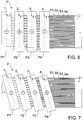
7 zeigt eine schematische Ansicht von vier Düsenreihen für eine Applikationsvorrichtung gemäß einer noch anderen Ausführungsform der Erfindung, -
8 zeigt eine schematische Ansicht von vier Düsenreihen für eine Applikationsvorrichtung gemäß einer Ausführungsform der Erfindung, -
9 zeigt eine schematische Ansicht von vier Düsenreihen für eine Applikationsvorrichtung gemäß einer anderen Ausführungsform der Erfindung, und -
10 zeigt eine schematische Ansicht von vier Düsenreihen für eine Applikationsvorrichtung gemäß einer wiederum anderen Ausführungsform der Erfindung, -
11 zeigt eine schematische Ansicht von vier Düsenreihen für eine Applikationsvorrichtung gemäß einer noch anderen Ausführungsform der Erfindung, -
12 zeigt eine schematische Ansicht von vier Düsenreihen für eine Applikationsvorrichtung gemäß einer noch anderen Ausführungsform der Erfindung, -
13 zeigt eine schematische Ansicht einer Mechanik zur Kopplung/Führung von Düsenreihen für eine Applikationsvorrichtung gemäß einer Ausführungsform der Erfindung -
14 zeigt eine schematische Ansicht der Düsenreihen der13 in positionsangepasster Stellung, -
15 zeigt eine schematische Ansicht einer Mechanik zur Kopplung/Führung von Düsenreihen für eine Applikationsvorrichtung gemäß einer anderen Ausführungsform der Erfindung -
16 zeigt eine schematische Ansicht der Düsenreihen der15 in positionsangepasster Stellung, -
17 zeigt eine schematische Ansicht zur Veranschaulichung eines Problems, wenn Düsen eines Druckkopfs z. B. aufgrund baulicher Randbedingungen nicht eng genug zueinander positioniert werden können, -
18 zeigt eine schematische Ansicht zur Veranschaulichung, wenn mehrere Druckköpfe zur Erhöhung der Flächenleistung und/oder zur Ermöglichung eines homogenen Applikationsmittelfils gemäß einer Ausführungsform der Erfindung hintereinander angeordnet sind, -
19 und 20 zeigen schematische Ansichten zur Veranschaulichung eines Problems, wenn mehrere hintereinander angeordnete Druckköpfe durch einen Applikationsroboter verdreht werden, -
21 zeigt zwei Applikationsroboter gemäß einer Ausführungsform der Erfindung, und -
22 zeigt einen Teils eines Druckkopfs gemäß einer Ausführungsform der Erfindung.
-
1 shows a schematic view of three Nozzle rows for an application device according to an embodiment of the invention, -
2 shows a schematic view of the three nozzle rows of1 in position-adjusted position, -
3 shows a schematic view illustrating the principle of operation of an application device according to an embodiment of the invention, -
4 shows a schematic view of four nozzle rows for an application device according to an embodiment of the invention, -
5 shows a schematic view of four nozzle rows for an application device according to another embodiment of the invention, -
6 shows a schematic view of four nozzle rows for an application device according to yet another embodiment of the invention, -
7 shows a schematic view of four nozzle rows for an application device according to yet another embodiment of the invention, -
8th shows a schematic view of four nozzle rows for an application device according to an embodiment of the invention, -
9 shows a schematic view of four nozzle rows for an application device according to another embodiment of the invention, and -
10 shows a schematic view of four nozzle rows for an application device according to yet another embodiment of the invention, -
11 shows a schematic view of four nozzle rows for an application device according to yet another embodiment of the invention, -
12 shows a schematic view of four nozzle rows for an application device according to yet another embodiment of the invention, -
13 shows a schematic view of a mechanism for coupling / guiding nozzle rows for an application device according to an embodiment of the invention -
14 shows a schematic view of the nozzle rows of13 in position-adjusted position, -
15 shows a schematic view of a mechanism for coupling / guiding nozzle rows for an application device according to another embodiment of the invention -
16 shows a schematic view of the nozzle rows of15 in position-adjusted position, -
17 shows a schematic view for illustrating a problem when nozzles of a printhead z. B. can not be positioned close enough to each other due to structural constraints, -
18 shows a schematic view for illustrating, when a plurality of printheads are arranged to increase the area performance and / or to enable a homogeneous Applikationsmittelfils according to an embodiment of the invention one behind the other, -
19 and20 show schematic views for illustrating a problem when a plurality of successively arranged print heads are rotated by an application robot, -
21 shows two application robot according to an embodiment of the invention, and -
22 shows a part of a printhead according to an embodiment of the invention.
Die unter Bezugnahme auf die Figuren beschriebenen bevorzugten Ausführungsformen der Erfindung stimmen teilweise überein, wobei ähnliche oder identische Teile mit den gleichen Bezugszeichen versehen sind, und zu deren Erläuterung auch auf die Beschreibung anderer Ausführungsformen oder Figuren verwiesen wird, um Wiederholungen zu vermeiden.The preferred embodiments of the invention described with reference to the figures are partly identical, with similar or identical parts being given the same reference numerals, and for the explanation of which reference is also made to the description of other embodiments or figures in order to avoid repetition.
Der Übersichtlichkeit halber sind in den Figuren meist nur jeweils eine Düse, nur ein zugehöriger Applikationsmittelstrahl und nur einige Düsenabstände mit Bezugszeichen versehen.For the sake of clarity, only one nozzle in each case, only one associated application agent jet and only a few nozzle distances are provided with reference symbols in the figures.
Die Applikationsvorrichtung
Die Applikationsvorrichtung
Der Druckkopf
Eine erste Düsenreihe
Eine zweite Düsenreihe
Eine dritte Düsenreihe
Bezugszeichen
Die drei Düsenreihen
Während eines Applikationsvorgangs wird es üblicherweise erforderlich, dass der Druckkopf
Die „Geometrie“ kann auch durch An- oder Abschalten erzeugt werden. Nur sind dann „Absätze“ in Größe des Düsenabstandes im Lack sichtbar. Wenn das nicht akzeptabel bzw. gut genug für die optische Lösung für das lackierte Teil ist, dann bleibt nur das Verdrehen als Lösung.The "geometry" can also be generated by switching on or off. Only then are "paragraphs" visible in size of the nozzle spacing in the paint. If this is not acceptable or good enough for the optical solution for the painted part, then only the twisting remains as a solution.
Ein Verdrehen
Die zumindest drei Düsenreihen
Die Beweglichkeitsfunktion der drei Düsenreihen
Die Düsenabstände
Aus der Verdrehung
Trotz einer durch den Applikationsroboter erzeugten Verdrehung
Trotz der Verdrehung
Die drei Düsenplatten
So ist die erste Düsenreihe
Die drei Düsenreihen
Eine Steuerung, z.B. eine Robotersteuerungssoftware, könnte je nach Verdrehwinkel die Lackauftreffpunkte auf der Oberfläche berechnen und entsprechend korrigieren, so dass die vorhandenen Bahndaten entsprechend neu kalkuliert werden, d.h. eine Korrektur der Verschiebung der Lackauftreffpunkte und eine Korrektur der Bahnen, da sich die Bahnbreite ändert. A controller, e.g. Depending on the angle of rotation, a robot control software could calculate the paint impact points on the surface and correct them accordingly, so that the existing web data is recalculated accordingly, i. a correction of the shift of the Lackauftreffpunkte and a correction of the webs, as the web width changes.
Dies führt zu mehr oder weniger Bahnen, die automatisch korrigiert oder gar erzeugt werden können. Dies gilt für jede Art der Verdrehung. Auch schon bei nur einer Düsenreihe.This leads to more or fewer tracks that can be automatically corrected or even generated. This applies to any kind of distortion. Even with only one row of nozzles.
Die drei Düsenreihen
So kann z. B. die erste Düsenreihe
Zur Erzielung der Beweglichkeitsfunktion und/oder der Positionsanpassung sind folgende Varianten einzeln oder in Kombination miteinander möglich:To achieve the mobility function and / or the position adaptation, the following variants are possible individually or in combination with one another:
Die jeweilige Düsenreihe
Die jeweilige Düsenreihe
Es wird folglich ersichtlich, dass im Kontext der Erfindung zur Positionsanpassung zweckmäßig zumindest eine Düsenreihe relativ zu ihrem Druckkopf beweglich sein kann und/oder zumindest eine Düsenreihe gemeinsam mit ihrem Druckkopf beweglich sein kann.It will thus be appreciated that in the context of the invention for positional adjustment, at least one row of nozzles may conveniently be movable relative to its printhead and / or at least one row of nozzles may be movable together with its printhead.
Eine Besonderheit der in
Die erste Düsenreihe
Die zweite Düsenreihe
Die dritte Düsenreihe
Die vierte Düsenreihe
In
S kennzeichnet die Düsenabstände zwischen den Düsen
B kennzeichnet die Bahnbreite.B indicates the web width.
In
Allerdings können die einzelnen Düsenreihen
Eine Besonderheit der in
Die Abstände der Applikationsmittelauftreffpunkte zueinander und die Bahnbreite werden kleiner, die Abstände werden aber über die gesamte Bahnbreite gleich. Daraus folgt insbesondere eine gleichmäßige Schichtdickenverteilung und ein optimales Lackierergebnis.The distances of the Anwendungsmittelauftreffpunkte each other and the web width are smaller, but the distances are equal over the entire web width. This results in particular in a uniform layer thickness distribution and an optimal coating result.
D kennzeichnet die Düsenabstände zwischen den Düsen
E kennzeichnet die Bahnbreite.E denotes the web width.
Es gilt mit Blick auf die
- α = Drehwinkel zur Positionsanpassung
- D kleiner S
- E kleiner B
- α = rotation angle for position adjustment
- D small s
- E small B
Es gilt mit Blick auf die
- β = Drehwinkel zur Positionsanpassung
- D kleiner S
- E kleiner B
- β = angle of rotation for position adjustment
- D small s
- E small B
Es gilt mit Blick auf die
- ү = Drehwinkel zur Positionsanpassung
- D kleiner S
- E kleiner B
- ү = rotation angle for position adjustment
- D small s
- E small B
Die erste Düsenreihe
In einer besonderen Ausführung liegen die Drehachsen
In
Die Düsenplatten
Eine weitere Besonderheit ist, dass die Drehachsen
Die
In
Der Applikationsroboter
Der Antrieb
Das zu applizierende Applikationsmittel wird über eine Applikationsmittelzuführung
Die Platte
In dem Spulenrohr
Darüber hinaus befindet sich in dem Spulenrohr
Die Rückstellfeder
In einem ersten Betriebsmodus kann die Spule
In einem zweiten Betriebsmodus kann die Spule
Allgemein ist noch zu erwähnen, dass die beim Applikationsvorgang resultierenden Auftreffpunkte der Applikationsmittelstrahlen, die im Kontext der Erfindung als zusammenhängende Applikationsmittelstrahlen und/oder Tropfen umfassende Tropfenstrahlen realisier werden können, vorzugsweise zueinander denselben Mitten-Abstand aufweisen, so dass beim Verlaufen (Ausbreiten) des Applikationsmittels auf dem Bauteil ein homogener Applikationsmittelfilm entstehen kann.In general, it should also be mentioned that the impact points of the application agent beams resulting from the application process, which can be realized in the context of the invention as droplet jets comprising coherent application agent jets and / or droplets, preferably have the same center distance to one another, so that during spreading (spreading) of the application agent on the component a homogeneous application agent film can arise.
Die Erfindung ist nicht auf die vorstehend beschriebenen bevorzugten Ausführungsbeispiele beschränkt. Vielmehr ist eine Vielzahl von Varianten und Abwandlungen möglich, die ebenfalls von dem Erfindungsgedanken Gebrauch machen und deshalb in den Schutzbereich fallen. Insbesondere beansprucht die Erfindung auch Schutz für den Gegenstand und die Merkmale der Unteransprüche unabhängig von den jeweils in Bezug genommenen Ansprüchen und insbesondere auch ohne die Merkmale des Hauptanspruchs. Die Erfindung umfasst also verschiedene Erfindungsaspekte, die unabhängig voneinander Schutz genießen.The invention is not limited to the preferred embodiments described above. Rather, a variety of variants and modifications is possible, which also make use of the inventive idea and therefore fall within the scope. In particular, the invention also claims protection for the subject matter and the features of the dependent claims independently of the claims in each case referred to and in particular without the features of the main claim. The invention thus encompasses various aspects of the invention which enjoy protection independently of each other.
BezugszeichenlisteLIST OF REFERENCE NUMBERS
- 11
- Düsenreihenozzle row
- 1.11.1
- Düsenjet
- P1P1
- Düsenplattenozzle plate
- S1S1
- Applikationsmittelstrahlen, z. B. zusammenhängende Applikationsmittelstrahlen oder TropfenstrahlenApplication agent jets, z. B. contiguous application agent beams or droplets
- D1D1
- Drehachse axis of rotation
- 22
- Düsenreihenozzle row
- 2.12.1
- Düsenjet
- P2P2
- Düsenplattenozzle plate
- S2S2
- Applikationsmittelstrahlen, z. B. zusammenhängende Applikationsmittelstrahlen oder TropfenstrahlenApplication agent jets, z. B. contiguous application agent beams or droplets
- D2D2
- Drehachse axis of rotation
- 33
- Düsenreihenozzle row
- 3.13.1
- Düsenjet
- P3P3
- Düsenplattenozzle plate
- S3S3
- Applikationsmittelstrahlen, z. B. zusammenhängende Applikationsmittelstrahlen oder TropfenstrahlenApplication agent jets, z. B. contiguous application agent beams or droplets
- D3D3
- Drehachse axis of rotation
- 44
- Düsenreihenozzle row
- 4.14.1
- Düsenjet
- P4P4
- Düsenplattenozzle plate
- S4S4
- Applikationsmittelstrahlen, z. B. zusammenhängende Applikationsmittelstrahlen oder TropfenstrahlenApplication agent jets, z. B. contiguous application agent beams or droplets
- D4D4
- Drehachse axis of rotation
- S, DS, D
- Düsenabstände, vorzugsweise senkrecht zur zweckmäßig translatorischen Bewegungsrichtung des zumindest eines DruckkopfsNozzle distances, preferably perpendicular to the expedient translational movement direction of the at least one print head
- B, EB, E
- Bahnbreiteweb width
- XX
- Verdrehung, vorzugsweise Applikationsroboter-verursachtTwist, preferably application robot-caused
- VV
- Applikationsvorrichtungapplicator
- 100100
- Druckkopfprinthead
- 101101
- Druckkopfprinthead
- 102102
- Druckkopfprinthead
- MM
- Druckkopf-Bewegungsrichtung, vorzugsweise translatorischPrint head movement direction, preferably translational
- RR
- Applikationsroboterapplication robot
- TT
- Bauteil, vorzugsweise Kraftfahrzeugkarosserie Component, preferably motor vehicle body
- 2020
- Ventilelement, vorzugsweise Anker und/oder VentilnadelValve element, preferably anchor and / or valve needle
- 21 A21 A
- Antrieb, insbesondere VentilantriebDrive, in particular valve drive
- 2222
- SpuleKitchen sink
- 2323
- RückstellelementReturn element
- 2424
- ApplikationsmittelzuführungApplication medium feed
- 2525
- Platteplate
- 2626
- Spulenrohrcoil tube
- 2727
- SpulenkernPlunger
- 2828
- Dichtung zwischen Spulenkern und SpulenrohrSeal between coil core and coil tube
ZITATE ENTHALTEN IN DER BESCHREIBUNG QUOTES INCLUDE IN THE DESCRIPTION
Diese Liste der vom Anmelder aufgeführten Dokumente wurde automatisiert erzeugt und ist ausschließlich zur besseren Information des Lesers aufgenommen. Die Liste ist nicht Bestandteil der deutschen Patent- bzw. Gebrauchsmusteranmeldung. Das DPMA übernimmt keinerlei Haftung für etwaige Fehler oder Auslassungen.This list of the documents listed by the applicant has been generated automatically and is included solely for the better information of the reader. The list is not part of the German patent or utility model application. The DPMA assumes no liability for any errors or omissions.
Zitierte PatentliteraturCited patent literature
- US 9108424 B2 [0003]US 9108424 B2 [0003]
Claims (35)
Priority Applications (8)
| Application Number | Priority Date | Filing Date | Title |
|---|---|---|---|
| DE102016014920.5A DE102016014920A1 (en) | 2016-12-14 | 2016-12-14 | Printhead with sliding and / or rotating mechanism for at least one row of nozzles |
| ES17809258T ES2865429T3 (en) | 2016-12-14 | 2017-12-01 | Print head with a movement and / or rotation mechanism for at least one row of nozzles |
| US16/468,699 US12186763B2 (en) | 2016-12-14 | 2017-12-01 | Print head with a displacing mechanism for a nozzle row |
| EP17809258.1A EP3554713B1 (en) | 2016-12-14 | 2017-12-01 | Printing head with offset and/or rotation mechanism for at least a nozzle row |
| JP2019532024A JP7128817B2 (en) | 2016-12-14 | 2017-12-01 | Printhead with a displacement and/or rotation mechanism for at least one row of nozzles |
| CN201780077603.3A CN110072627B (en) | 2016-12-14 | 2017-12-01 | Jet printing head with translation and/or rotation mechanism for at least one jet nozzle row |
| MX2019006977A MX2019006977A (en) | 2016-12-14 | 2017-12-01 | Print head with a displacing and/or rotating mechanism for at least one nozzle row. |
| PCT/EP2017/081121 WO2018108572A1 (en) | 2016-12-14 | 2017-12-01 | Print head with a displacing and/or rotating mechanism for at least one nozzle row |
Applications Claiming Priority (1)
| Application Number | Priority Date | Filing Date | Title |
|---|---|---|---|
| DE102016014920.5A DE102016014920A1 (en) | 2016-12-14 | 2016-12-14 | Printhead with sliding and / or rotating mechanism for at least one row of nozzles |
Publications (1)
| Publication Number | Publication Date |
|---|---|
| DE102016014920A1 true DE102016014920A1 (en) | 2018-06-14 |
Family
ID=60582579
Family Applications (1)
| Application Number | Title | Priority Date | Filing Date |
|---|---|---|---|
| DE102016014920.5A Withdrawn DE102016014920A1 (en) | 2016-12-14 | 2016-12-14 | Printhead with sliding and / or rotating mechanism for at least one row of nozzles |
Country Status (8)
| Country | Link |
|---|---|
| US (1) | US12186763B2 (en) |
| EP (1) | EP3554713B1 (en) |
| JP (1) | JP7128817B2 (en) |
| CN (1) | CN110072627B (en) |
| DE (1) | DE102016014920A1 (en) |
| ES (1) | ES2865429T3 (en) |
| MX (1) | MX2019006977A (en) |
| WO (1) | WO2018108572A1 (en) |
Cited By (2)
| Publication number | Priority date | Publication date | Assignee | Title |
|---|---|---|---|---|
| FR3087705A1 (en) * | 2018-10-26 | 2020-05-01 | Psa Automobiles Sa | INK JET PRINTING ON A COMPLEX SURFACE |
| DE102020127852A1 (en) | 2020-10-22 | 2022-04-28 | Dürr Systems Ag | Operating procedure for a coating plant and correspondingly adapted coating plant |
Families Citing this family (12)
| Publication number | Priority date | Publication date | Assignee | Title |
|---|---|---|---|---|
| US11400477B2 (en) | 2018-01-30 | 2022-08-02 | Ford Motor Company | Reversible nozzle in ultrasonic atomizer for clog prevention |
| CN110901231B (en) * | 2019-12-26 | 2020-12-29 | 博兴战新产业发展有限公司 | An ink line correction device for the nozzle of a jet printer |
| JP7187732B2 (en) | 2020-04-07 | 2022-12-12 | アーベーベー・シュバイツ・アーゲー | Inkjet type vehicle coating machine and vehicle coating method |
| US12458992B2 (en) | 2020-06-18 | 2025-11-04 | Abb Schweiz Ag | Painting robot and painting method using painting robot |
| JP6948482B1 (en) * | 2021-03-25 | 2021-10-13 | アーベーベー・シュバイツ・アーゲーABB Schweiz AG | Painting robot system and painting method |
| CN113492082A (en) * | 2021-06-30 | 2021-10-12 | 镭德杰标识科技武汉有限公司 | Spraying device, coding system and coating spraying method |
| JP7687117B2 (en) | 2021-07-30 | 2025-06-03 | セイコーエプソン株式会社 | Method for controlling robot system and robot system |
| JP7666199B2 (en) * | 2021-07-30 | 2025-04-22 | セイコーエプソン株式会社 | Method for controlling robot system and robot system |
| DE102021133410A1 (en) | 2021-12-16 | 2023-06-22 | Dürr Systems Ag | Coating equipment and related operating procedure |
| EP4201685B1 (en) * | 2021-12-27 | 2024-07-31 | Ricoh Company, Ltd. | Liquid discharge apparatus, liquid discharge method, and carrier medium |
| CN115837805B (en) * | 2023-02-22 | 2023-05-26 | 苏州优备精密智能装备股份有限公司 | Device for realizing ink jet printing on side edge of display panel and ink jet printing control method thereof |
| JP7547664B1 (en) | 2024-02-05 | 2024-09-09 | アーベーベー・シュバイツ・アーゲー | Painting robot |
Citations (5)
| Publication number | Priority date | Publication date | Assignee | Title |
|---|---|---|---|---|
| US20050243112A1 (en) * | 2004-03-04 | 2005-11-03 | Shinya Kobayashi | Inkjet coating method and apparatus |
| EP1764226A1 (en) * | 2005-09-20 | 2007-03-21 | Agfa Graphics N.V. | A method and apparatus for automatically aligning arrays of printing elements |
| EP1852733A1 (en) * | 2001-01-15 | 2007-11-07 | Seiko Epson Corporation | Material discharging apparatus and method for producing color filters, liquid crystal and electroluminescent devices |
| DE102014006991A1 (en) * | 2013-06-06 | 2014-12-11 | Heidelberger Druckmaschinen Ag | Apparatus for printing with an ink jet printhead on a curved surface of an obiect |
| US9108424B2 (en) | 2010-10-27 | 2015-08-18 | Matthews Resources, Inc. | Valve jet printer with inert plunger tip |
Family Cites Families (236)
| Publication number | Priority date | Publication date | Assignee | Title |
|---|---|---|---|---|
| DE1284250B (en) | 1965-10-30 | 1968-11-28 | Kaercher Fa Alfred | Sprayer for spraying a liquid mixture |
| US3717306A (en) | 1971-03-10 | 1973-02-20 | Hushon R | Nozzle for spraying foaming materials |
| US3981320A (en) | 1974-05-10 | 1976-09-21 | The Gyromat Corporation | Recovery system for spray painting installation with automatic color change |
| AT349415B (en) | 1975-07-28 | 1979-04-10 | Zimmer Peter Ag | INJECTION PRESSURE DEVICE FOR SAMPLING OF A GOODS |
| CH613387A5 (en) | 1975-07-28 | 1979-09-28 | Zimmer Peter Maschinenfabrik A | Process and device for applying patterns to a material, in particular to a web material |
| US4383264A (en) | 1980-06-18 | 1983-05-10 | Exxon Research And Engineering Co. | Demand drop forming device with interacting transducer and orifice combination |
| JPS5722070A (en) | 1980-07-15 | 1982-02-04 | Oki Electric Ind Co Ltd | Cooling device for printer |
| US4375865A (en) | 1980-08-12 | 1983-03-08 | Binks Manufacturing Company | Color change system for spray coating apparatus |
| DE3045401A1 (en) | 1980-12-02 | 1982-07-01 | Robert Bosch Gmbh, 7000 Stuttgart | PROCESS FOR INJECTING INJECTORS |
| MX152277A (en) | 1980-12-16 | 1985-06-19 | Vitro Tec Fideicomiso | IMPROVEMENTS IN SOLENOID PNEUMATIC VALVE BLOCKS FOR GLASS ARTICLE MANUFACTURING MACHINES |
| US4423999A (en) | 1981-09-14 | 1984-01-03 | General Motors Corporation | Mechanical hand for a door-opener |
| US4435719A (en) | 1982-03-30 | 1984-03-06 | Snaper Alvin A | Fluidic matrix printer |
| DE3221327A1 (en) | 1982-06-05 | 1983-09-15 | Daimler-Benz Ag, 7000 Stuttgart | Plant for colour spraying of series-production parts of changing colour |
| DE3225554A1 (en) | 1982-07-08 | 1984-01-12 | Robert Bosch Gmbh, 7000 Stuttgart | Measuring device for fluid jets |
| US4668948A (en) | 1983-03-10 | 1987-05-26 | Nordson Corporation | Dispenser malfunction detector |
| US4555719A (en) | 1983-08-19 | 1985-11-26 | Videojet Systems International, Inc. | Ink valve for marking systems |
| US4593360A (en) | 1983-12-16 | 1986-06-03 | Cocks Eric H | Fluid spray control system |
| WO1986001775A1 (en) | 1984-09-19 | 1986-03-27 | Ronald Douglas Drysdale | Method of and apparatus for applying images to a surface |
| JPS624464A (en) | 1985-07-02 | 1987-01-10 | Honda Motor Co Ltd | Device for painting automobile body |
| JPS62116442A (en) | 1985-11-12 | 1987-05-28 | Toppan Printing Co Ltd | Double feed sensing device |
| DD245400A1 (en) | 1986-02-05 | 1987-05-06 | Robotron Bueromasch | COLOR JET HEAD |
| US4875058A (en) | 1986-12-12 | 1989-10-17 | Markpoint System Ab | Valve device for a matrix printer |
| US4734711A (en) | 1986-12-22 | 1988-03-29 | Eastman Kodak Company | Pressure regulation system for multi-head ink jet printing apparatus |
| SE456597B (en) | 1987-02-12 | 1988-10-17 | Scandot System Ab | DEVICE FOR A VALVE ARRANGEMENT FOR THE EXHAUST OF LIQUID BY A SCRIPLINE PRINTER |
| DE3721875A1 (en) | 1987-07-02 | 1989-01-12 | Gema Ransburg Ag | METHOD AND DEVICE FOR A POWDER SPRAY COATING SYSTEM |
| JPH0798171B2 (en) | 1988-04-19 | 1995-10-25 | トキコ株式会社 | Industrial robot equipment |
| US4974780A (en) | 1988-06-22 | 1990-12-04 | Toa Nenryo Kogyo K.K. | Ultrasonic fuel injection nozzle |
| US5050533A (en) | 1988-07-25 | 1991-09-24 | Technadyne Engineering Corporation | Application of thermal-cure materials |
| US5602575A (en) | 1988-11-05 | 1997-02-11 | Rea Elektronik Gmbh | Ink jet writing head |
| US4894252A (en) | 1988-11-30 | 1990-01-16 | Ransburg Corporation | Coating material orifice clogging indication method and apparatus |
| US4985715A (en) * | 1990-03-22 | 1991-01-15 | Telesis Controls Corporation | Marker assembly for spray marking dot matrix characters and method of fabrication thereof |
| DE4013322A1 (en) | 1990-04-26 | 1991-10-31 | Heino Kaiser | Multiple applicator head for flowing medium - has several controlled feed valves fitted in modular structure in frame-type head |
| JP3144566B2 (en) | 1990-05-08 | 2001-03-12 | マツダ株式会社 | Painting method and painting equipment |
| US5072881A (en) | 1990-06-04 | 1991-12-17 | Systems Specialties | Method of cleaning automated paint spraying equipment |
| JPH04106669U (en) | 1991-02-21 | 1992-09-14 | セントラル自動車株式会社 | Water-based painting booth |
| DE4138491C2 (en) | 1991-11-23 | 1995-07-20 | Juergen Dipl Ing Joswig | Micromechanical valve for micromechanical dosing devices |
| US5429682A (en) | 1993-08-19 | 1995-07-04 | Advanced Robotics Technologies | Automated three-dimensional precision coatings application apparatus |
| DE4329384C2 (en) | 1993-09-01 | 2001-08-09 | Duerr Systems Gmbh | Conveyor |
| DE9422327U1 (en) | 1993-09-01 | 2000-03-23 | Dürr Systems GmbH, 70435 Stuttgart | Coating system |
| US6164746A (en) * | 1993-09-24 | 2000-12-26 | Canon Kabushiki Kaisha | Ink-jet printer method and apparatus, color filter, display device, apparatus having display device, ink-jet head unit adjusting device and method, and ink-jet head unit |
| US5435884A (en) | 1993-09-30 | 1995-07-25 | Parker-Hannifin Corporation | Spray nozzle and method of manufacturing same |
| GB2286157B (en) | 1994-01-31 | 1998-01-14 | Neopost Ltd | Ink jet printing device |
| DE9405600U1 (en) | 1994-04-02 | 1994-06-16 | ITW Dynatec Klebetechnik Holding GmbH, 40699 Erkrath | Application head for the metered delivery of flowing media |
| CN2287527Y (en) | 1994-04-20 | 1998-08-12 | 徐连宽 | Fuel burning type paint spray and baking vanish booth |
| US5718767A (en) | 1994-10-05 | 1998-02-17 | Nordson Corporation | Distributed control system for powder coating system |
| US5659347A (en) | 1994-11-14 | 1997-08-19 | Xerox Corporation | Ink supply apparatus |
| US5647542A (en) | 1995-01-24 | 1997-07-15 | Binks Manufacturing Company | System for electrostatic application of conductive coating liquid |
| US5636795A (en) | 1995-05-11 | 1997-06-10 | First Pioneer Industries Inc. | Cyclonic spray nozzle |
| SE504472C2 (en) | 1995-06-22 | 1997-02-17 | Abb Flexible Automation As | Color feeding system for spray painting robot |
| JPH09192583A (en) | 1996-01-17 | 1997-07-29 | Fuji Heavy Ind Ltd | Box for keeping roller type coating device |
| DE19606716C1 (en) | 1996-02-23 | 1997-08-14 | Herberts Gmbh | Process for multi-layer painting |
| SE507821C2 (en) | 1996-04-15 | 1998-07-20 | Jetline Ab | Valve construction with ink jet printers |
| DE19630290C2 (en) | 1996-07-26 | 2000-08-10 | Audi Ag | System for the surface treatment of objects, in particular vehicle bodies |
| JP2978459B2 (en) * | 1996-09-30 | 1999-11-15 | キヤノン株式会社 | Method and apparatus for manufacturing color filter, color filter, display apparatus, and apparatus having display apparatus |
| DE19731829A1 (en) | 1997-07-24 | 1999-01-28 | Tietz Patrick | Colour mixing and dosing unit for enamels, paints etc.using paint delivery unit atomising paint |
| DE19743804A1 (en) | 1997-10-02 | 1999-04-08 | Politrust Ag | Large format printing using ink-jet printer |
| ES2273444T3 (en) | 1998-01-13 | 2007-05-01 | Abb K.K. | COATING METHOD FOR A ROTATING ATOMIZING HEAD TYPE COATING DEVICE. |
| CN1272270C (en) | 1998-08-13 | 2006-08-30 | Ppg工业俄亥俄公司 | a coating method |
| DE19852079A1 (en) | 1998-11-11 | 2000-05-18 | Thomas Kovarovsky | Image generating painting arrangement has controller with device that reacts to image information by actuating robot arm, dosing device to reproduce image on painted surface |
| JP2000158670A (en) | 1998-11-26 | 2000-06-13 | Fuji Electric Co Ltd | Ink jet recording device |
| JP4358352B2 (en) | 1999-05-11 | 2009-11-04 | トリニティ工業株式会社 | Coating device, coating machine used therefor, and coating method using the same |
| DE19936790A1 (en) | 1999-08-10 | 2001-02-15 | Nordson Corp Westlake | Method and device for producing a removable protective layer for surfaces, in particular for painted surfaces of motor vehicle bodies |
| JP2001157863A (en) | 1999-09-21 | 2001-06-12 | Tokyo Electron Ltd | Coating device |
| JP2001129456A (en) | 1999-11-04 | 2001-05-15 | Sekisui Chem Co Ltd | Nozzle cleaning method in spray coating apparatus and spray coating apparatus |
| IT1311388B1 (en) | 1999-11-10 | 2002-03-12 | Gd Spa | SPRAY RUBBER UNIT. |
| US6325302B1 (en) | 1999-11-29 | 2001-12-04 | Fanuc Robotics North America, Inc. | Airless spray tool |
| JP2001162841A (en) * | 1999-12-07 | 2001-06-19 | Seiko Epson Corp | Printing that performs bidirectional printing or unidirectional printing in parallel for each type of ink |
| DE20017630U1 (en) | 1999-12-20 | 2001-03-22 | Tevkür, Talip, 13585 Berlin | Paint spray gun |
| KR100335955B1 (en) | 1999-12-30 | 2002-05-10 | 이계안 | Coating system for protecting film |
| EP1120258B1 (en) | 2000-01-21 | 2006-05-17 | Seiko Epson Corporation | Ink cartridge, and ink-jet recording apparatus using the same |
| US6360656B2 (en) * | 2000-02-28 | 2002-03-26 | Minolta Co., Ltd. | Apparatus for and method of printing on three-dimensional object |
| JP2001239652A (en) | 2000-02-28 | 2001-09-04 | Minolta Co Ltd | Printer and printing method |
| US6460958B2 (en) | 2000-02-29 | 2002-10-08 | Minolta Co., Ltd. | Three-dimensional object printing apparatus and method |
| US6401976B1 (en) | 2000-03-23 | 2002-06-11 | Nordson Corporation | Electrically operated viscous fluid dispensing apparatus and method |
| DE10031030B4 (en) | 2000-06-26 | 2005-08-04 | Bauer, Jörg R. | Method and device for producing flat components with a predetermined surface appearance and planar component, in particular front panel of a kitchen element |
| FR2811917B1 (en) | 2000-07-24 | 2002-12-20 | Sames Sa | PRODUCT CHANGE METHOD AND STATION IN A COATING PRODUCT SPRAYING SYSTEM |
| US6641667B2 (en) | 2000-08-29 | 2003-11-04 | Honda Giken Kogyo Kabushiki Kaisha | Robot-mounted two-package-mixing coating device and internal pressure explosion-proof robot |
| US6523921B2 (en) | 2000-08-30 | 2003-02-25 | L&P Property Management | Method and apparatus for printing on rigid panels and other contoured or textured surfaces |
| WO2002018053A1 (en) | 2000-08-30 | 2002-03-07 | Cartesian Technologies, Inc. | Method and apparatus for high-speed microfluidic dispensing using text file control |
| DE10048749A1 (en) | 2000-09-29 | 2002-04-11 | Josef Schucker | Arrangement for applying adhesive to a workpiece |
| US6849684B2 (en) | 2000-10-20 | 2005-02-01 | E. I. Du Pont De Nemours And Company | Molded soft elastomer/hard polyester composition with noise damping properties |
| US7244310B2 (en) | 2001-06-01 | 2007-07-17 | Litrex Corporation | Over-clocking in a microdeposition control system to improve resolution |
| US7449070B2 (en) | 2001-06-01 | 2008-11-11 | Ulvac, Inc. | Waveform generator for microdeposition control system |
| US7160105B2 (en) | 2001-06-01 | 2007-01-09 | Litrex Corporation | Temperature controlled vacuum chuck |
| US20040231594A1 (en) | 2001-06-01 | 2004-11-25 | Edwards Charles O. | Microdeposition apparatus |
| KR100924002B1 (en) | 2001-06-01 | 2009-10-28 | 가부시키가이샤 아루박 | Industrial microdeposition apparatus for polymer light emitting diode display, printed circuit board, etc. |
| US20050016451A1 (en) | 2001-06-01 | 2005-01-27 | Edwards Charles O. | Interchangeable microdesition head apparatus and method |
| JP4158357B2 (en) | 2001-06-05 | 2008-10-01 | セイコーエプソン株式会社 | Inkjet recording device |
| DE10130499A1 (en) | 2001-06-25 | 2003-01-02 | Duerr Systems Gmbh | Coating system and method for controlling a coating device with different nozzles |
| US6755512B2 (en) | 2001-07-30 | 2004-06-29 | Fuji Photo Film Co. Ltd | Liquid droplet ejection apparatus and inkjet recording head |
| JP3487301B2 (en) | 2001-08-06 | 2004-01-19 | マツダ株式会社 | Painting method and painting equipment for automobile body |
| DE10140216B4 (en) | 2001-08-17 | 2006-02-09 | ITW Oberflächentechnik GmbH & Co. KG | Method and device on a painting device for cleaning a paint delivery line |
| US6757586B2 (en) | 2001-09-05 | 2004-06-29 | Abb Automation Inc. | Multiple arm robot arrangement |
| CN1232839C (en) * | 2001-09-28 | 2005-12-21 | 兄弟工业株式会社 | Liquid drop pattern forming device |
| JP3961820B2 (en) | 2001-11-30 | 2007-08-22 | 株式会社不二越 | Industrial robot controller |
| WO2003062129A2 (en) | 2002-01-22 | 2003-07-31 | Nordson Corporation | Method and apparatus for detecting a liquid spray pattern |
| DE10307719A1 (en) | 2002-03-01 | 2003-09-11 | Vmt Bildverarbeitungssysteme G | Quality assurance for application of medium to object involves allowing coating of target object depending on comparison of result of coating test object with stored desired properties |
| DE10224128A1 (en) | 2002-05-29 | 2003-12-18 | Schmid Rhyner Ag Adliswil | Method of applying coatings to surfaces |
| US20040173144A1 (en) | 2002-05-31 | 2004-09-09 | Edwards Charles O. | Formation of printed circuit board structures using piezo microdeposition |
| CA2651806C (en) | 2002-10-23 | 2012-06-05 | Fanuc Robotics America, Inc. | Robotic apparatus for painting |
| JP4123897B2 (en) | 2002-10-28 | 2008-07-23 | 株式会社エルエーシー | Inkjet nozzle |
| WO2004041444A1 (en) | 2002-11-06 | 2004-05-21 | Advanced Flow Control Afc Ab | System for spraying a fluid material |
| SE0203515L (en) | 2002-11-27 | 2004-05-28 | Texdot Ab | Valve unit in a liquid jet printer and method at such a unit |
| CN1194821C (en) | 2002-11-28 | 2005-03-30 | 上海交通大学 | Nozzle for large-area uniform transparent conducting film |
| US7454785B2 (en) | 2002-12-19 | 2008-11-18 | Avocent Huntsville Corporation | Proxy method and system for secure wireless administration of managed entities |
| JP3885036B2 (en) | 2003-03-14 | 2007-02-21 | 本田技研工業株式会社 | Method and apparatus for applying protective layer forming material |
| GB0306788D0 (en) * | 2003-03-25 | 2003-04-30 | Willett Int Ltd | Method |
| US7178742B2 (en) | 2003-05-06 | 2007-02-20 | Lear Corporation | Fluid delivery system for spray applicator |
| JP2004337710A (en) | 2003-05-14 | 2004-12-02 | Trinity Ind Corp | Controller and controlling method of coating robot |
| US20050001869A1 (en) | 2003-05-23 | 2005-01-06 | Nordson Corporation | Viscous material noncontact jetting system |
| DE10331206A1 (en) | 2003-07-10 | 2005-01-27 | Daimlerchrysler Ag | Spray material is applied to a workpiece by directing a spray jet of an applicator, monitoring the jet geometry, and comparing it with a predetermined geometry |
| US20050015050A1 (en) | 2003-07-15 | 2005-01-20 | Kimberly-Clark Worldwide, Inc. | Apparatus for depositing fluid material onto a substrate |
| ZA200407781B (en) | 2003-10-03 | 2005-09-28 | Int Tech Llc | Blasting and blastiing accessory |
| FR2862563B1 (en) | 2003-11-24 | 2007-01-19 | Centre Nat Rech Scient | A LARGE-SIZE DIGITAL DIGITAL PRINTING ROBOT ON A FIXED SURFACE AND A PRINTING METHOD USING AT LEAST ONE SUCH ROBOT |
| KR100848162B1 (en) * | 2004-01-19 | 2008-07-23 | 삼성전자주식회사 | Inkjet Printing Device and Head Position Adjustment Method |
| RU2350463C2 (en) | 2004-02-03 | 2009-03-27 | Линде Акциенгезельшафт | Device to apply coatings on product surfaces |
| DE102004034270B4 (en) | 2004-07-15 | 2016-08-18 | Wolfgang Schmidt | Plant for discharging flowable fluids, in particular paints and varnishes and method for operating the system |
| US8342636B2 (en) | 2004-08-23 | 2013-01-01 | Kabushiki Kaisha Ishiihyoki | Discharge rate control method for ink-jet printer, ink spread inspecting method, and oriented film forming method |
| DE102004044655B4 (en) | 2004-09-15 | 2009-06-10 | Airbus Deutschland Gmbh | Painting device, painting arrangement, method for painting a curved surface of an aircraft and use of an inkjet device for painting an aircraft |
| US20060068109A1 (en) | 2004-09-15 | 2006-03-30 | Airbus Deutschland Gmbh | Painting device, painting arrangement, method for painting a curved surface of an object, and use of an inkjet device for painting an aircraft |
| US7824001B2 (en) | 2004-09-21 | 2010-11-02 | Z Corporation | Apparatus and methods for servicing 3D printers |
| DE102004049471A1 (en) | 2004-10-11 | 2006-04-20 | Bayerische Motoren Werke Ag | Device for applying preserving coating to vehicle comprises nozzle strip with controllable spray nozzles arranged to also only spray in partial areas |
| JP2007021760A (en) | 2005-07-12 | 2007-02-01 | Nissha Printing Co Ltd | Forming apparatus of thin film |
| CN101309755A (en) | 2005-12-01 | 2008-11-19 | 3M创新有限公司 | Multi-component liquid spray systems |
| JP2007152666A (en) | 2005-12-02 | 2007-06-21 | Seiko Epson Corp | Droplet observation device |
| JP4432922B2 (en) | 2006-03-17 | 2010-03-17 | セイコーエプソン株式会社 | Droplet discharge device |
| DE102006017956B4 (en) | 2006-04-18 | 2016-01-07 | OuISS Qualitäts-Inspektionssysteme und Service AG | Method for applying and monitoring a job structure with repair function and device therefor |
| JP4705877B2 (en) | 2006-04-25 | 2011-06-22 | トリニティ工業株式会社 | Top coating equipment and coating method using the same |
| DE102006021623A1 (en) | 2006-05-09 | 2007-11-15 | Dürr Systems GmbH | Dosing system for a coating system |
| ES2556171T3 (en) | 2006-05-12 | 2016-01-13 | Dürr Systems GmbH | Coating installation and corresponding operating procedure |
| EP1884365A1 (en) | 2006-07-28 | 2008-02-06 | Abb Research Ltd. | Paint applicator and coating method |
| KR100729553B1 (en) | 2006-10-27 | 2007-06-18 | 주식회사 탑 엔지니어링 | Dispensing apparatus |
| KR100833679B1 (en) | 2006-11-07 | 2008-05-29 | 포항공과대학교 산학협력단 | Droplet Mixing Apparatus and Droplet Mixing Method |
| DE102006056051B4 (en) | 2006-11-28 | 2018-09-20 | Robert Bosch Gmbh | Robot with control for additional axes |
| US8707976B2 (en) | 2006-11-29 | 2014-04-29 | Daryl Bauer | Portable painting apparatus |
| DE102007002980A1 (en) | 2007-01-19 | 2008-07-24 | Voith Patent Gmbh | Adhesive applicator for a paper or cardboard processing machine |
| JP5288135B2 (en) | 2007-03-08 | 2013-09-11 | 株式会社安川電機 | Painting system |
| DE102007018877B4 (en) | 2007-04-19 | 2010-03-04 | Hönig, Thomas | Method and material application device with a test device for the quality measurement of the application image of a spray nozzle and use of a test field |
| KR101592443B1 (en) | 2007-05-18 | 2016-02-18 | 무사시 엔지니어링 가부시키가이샤 | Liquid material discharge method and apparatus |
| EP2002898A1 (en) | 2007-06-14 | 2008-12-17 | J. Zimmer Maschinenbau Gesellschaft m.b.H. | Application device for applying a fluid onto a substrate with valve devices, method for cleaning the application device and valve device for application device |
| GB0712860D0 (en) | 2007-07-03 | 2007-08-08 | Eastman Kodak Co | continuous inkjet drop generation device |
| DE102007037663A1 (en) | 2007-08-09 | 2009-02-19 | Dürr Systems GmbH | Needle valve assembly |
| WO2009040112A2 (en) | 2007-09-25 | 2009-04-02 | Eads Deutschland Gmbh | Method for operating a gas turbine engine, power supplying device for conducting such method and aircraft using such method |
| EP2229282A1 (en) * | 2007-12-31 | 2010-09-22 | Exatec, LLC. | Apparatus and method for printing three-dimensional articles |
| US20090181182A1 (en) | 2008-01-10 | 2009-07-16 | Sloan Donald D | Multipurpose digital ink |
| DE102008018881B4 (en) | 2008-03-11 | 2020-10-01 | Atlas Copco Ias Gmbh | Method and device for applying a viscous material to a workpiece and use of a needle valve for a device for applying a viscous material to a workpiece |
| KR101681895B1 (en) | 2008-03-20 | 2016-12-05 | 듀르 시스템스 게엠베하 | Painting robot and associated operating method |
| JP2009243007A (en) | 2008-03-31 | 2009-10-22 | Brother Ind Ltd | Printing apparatus for fabric |
| DE102008045553A1 (en) | 2008-09-03 | 2010-03-04 | Dürr Systems GmbH | Painting device and associated method |
| DE102008053178A1 (en) | 2008-10-24 | 2010-05-12 | Dürr Systems GmbH | Coating device and associated coating method |
| DE102008061203A1 (en) | 2008-12-09 | 2010-06-10 | Rehau Ag + Co | Method for painting a three-dimensional surface of a component |
| JP2010241003A (en) | 2009-04-07 | 2010-10-28 | Seiko Epson Corp | Droplet discharge head |
| DE102009020064A1 (en) | 2009-05-06 | 2010-11-11 | Dürr Systems GmbH | Fluid valve, in particular recirculation valve for a paint shop |
| DE102009029946A1 (en) | 2009-06-19 | 2010-12-30 | Epainters GbR (vertretungsberechtigte Gesellschafter Burkhard Büstgens, 79194 Gundelfingen und Suheel Roland Georges, 79102 Freiburg) | Print head or dosing head |
| US8556373B2 (en) | 2009-06-19 | 2013-10-15 | Burkhard Buestgens | Multichannel-printhead or dosing head |
| DE102009038462A1 (en) | 2009-08-21 | 2011-03-03 | Dürr Systems GmbH | Tumbling piston pump for metering a coating agent |
| US8652581B2 (en) | 2009-10-09 | 2014-02-18 | Matthew Merchant | Method of using a spray gun and material produced thereby |
| DE102009052654A1 (en) | 2009-11-11 | 2011-05-12 | Dürr Systems GmbH | Device and method for the preservation of components |
| US8757511B2 (en) | 2010-01-11 | 2014-06-24 | AdvanJet | Viscous non-contact jetting method and apparatus |
| DE102010004496B4 (en) | 2010-01-12 | 2020-06-18 | Hermann Müller | Method for operating a device for coating and / or printing a workpiece |
| JP2011206958A (en) | 2010-03-29 | 2011-10-20 | Seiko Epson Corp | Liquid injection device, liquid injection head and method of detecting coming-out of nozzle |
| US8534574B2 (en) | 2010-04-08 | 2013-09-17 | Intel Corporation | Underfill material dispenser |
| DE202010005211U1 (en) * | 2010-04-15 | 2011-10-21 | Planatol System Gmbh | Application system for liquid media |
| JP5769384B2 (en) | 2010-04-20 | 2015-08-26 | キヤノン株式会社 | Ink cartridge and ink jet recording apparatus |
| DE102010019612A1 (en) | 2010-05-06 | 2011-11-10 | Dürr Systems GmbH | Coating device, in particular with an application device, and associated coating method that emits a droplets of coating agent droplet |
| JP5489887B2 (en) | 2010-06-30 | 2014-05-14 | 富士フイルム株式会社 | Liquid coating apparatus, liquid coating method, and nanoimprint system |
| EP2799150B1 (en) | 2013-05-02 | 2016-04-27 | Hexagon Technology Center GmbH | Graphical application system |
| EP2433716A1 (en) | 2010-09-22 | 2012-03-28 | Hexagon Technology Center GmbH | Surface spraying device with a nozzle control mechanism and a corresponding method |
| JP5215376B2 (en) | 2010-12-27 | 2013-06-19 | 富士ゼロックス株式会社 | Liquid circulation device, liquid circulation control program, liquid ejection device |
| CN102198434A (en) | 2010-12-29 | 2011-09-28 | 东莞市冠辉五金有限公司 | Automatic spraying process for precision hardware and spraying control method |
| DE102012005087A1 (en) | 2011-03-28 | 2012-10-04 | Heidelberger Druckmaschinen Aktiengesellschaft | Device for printing surfaces with multiple, movable print heads |
| JP5647940B2 (en) | 2011-04-26 | 2015-01-07 | タクボエンジニアリング株式会社 | Mobile terminal casing coating apparatus and mobile terminal casing coating method using the same |
| JP2012228643A (en) | 2011-04-26 | 2012-11-22 | Takubo Engineering Co Ltd | Coating system for casing of mobile terminal and coating method for casing of mobile terminal using the same |
| KR101334805B1 (en) | 2011-06-09 | 2013-11-29 | 한국생산기술연구원 | Layer structure and method for fabricating the same |
| JP2013158968A (en) | 2012-02-02 | 2013-08-19 | Seiko Epson Corp | Printing apparatus, and method of suppressing rise of temperature of print head unit |
| WO2013121565A1 (en) | 2012-02-16 | 2013-08-22 | 株式会社伊万里鉄鋼センター | Coating supplying printing device |
| CN102582260A (en) | 2012-02-17 | 2012-07-18 | 上海美杰彩喷材料有限公司 | Water-base resin ink-jet printer |
| JP5906841B2 (en) | 2012-03-14 | 2016-04-20 | マツダ株式会社 | Paint circulation device and paint circulation method |
| EP2641661B1 (en) | 2012-03-20 | 2016-05-11 | Hexagon Technology Center GmbH | Graphical application system |
| DE102012005650A1 (en) | 2012-03-22 | 2013-09-26 | Burkhard Büstgens | Coating of surfaces in the printing process |
| DE102012006371A1 (en) | 2012-03-29 | 2012-07-05 | Heidelberger Druckmaschinen Aktiengesellschaft | Method for printing image on body i.e. tank of e.g. passenger car, involves generating three or higher-dimension raster matrix data to control inkjet printhead, and printing image with inkjet printhead using raster data |
| DE102012006370A1 (en) | 2012-03-29 | 2013-10-02 | Heidelberger Druckmaschinen Aktiengesellschaft | System for printing on an object |
| DE102012212469B4 (en) | 2012-07-17 | 2022-10-06 | Peter Fornoff | Method for printing on a surface and device for printing on a surface |
| JP2014019140A (en) | 2012-07-23 | 2014-02-03 | Ricoh Co Ltd | Ejection state inspecting method, and droplet ejecting apparatus |
| DE102012017538A1 (en) | 2012-09-05 | 2014-03-06 | Heidelberger Druckmaschinen Ag | Process for imaging and / or varnishing the surface of objects |
| DE102012109123A1 (en) | 2012-09-27 | 2014-03-27 | Vermes Microdispensing GmbH | Dosing system, dosing process and manufacturing process |
| GB2507069A (en) | 2012-10-17 | 2014-04-23 | Siemens Plc | Monitoring the quality of an electrostatic coating by measuring light reflected from a spray |
| KR20190123811A (en) * | 2012-12-27 | 2019-11-01 | 카티바, 인크. | Techniques for print ink volume control to deposit fluids within precise tolerances |
| JP5494846B2 (en) | 2013-01-23 | 2014-05-21 | セイコーエプソン株式会社 | Inkjet head unit and printing apparatus |
| DE102013002412A1 (en) | 2013-02-11 | 2014-08-14 | Dürr Systems GmbH | Application method and application system |
| DE202013101134U1 (en) | 2013-03-15 | 2014-06-17 | Vermes Microdispensing GmbH | metering valve |
| ITMO20130069A1 (en) | 2013-03-15 | 2014-09-16 | Tecno Italia S R L | HEAD FOR THE DIGITAL DECORATION OF CERAMIC MANUFACTURES |
| DE102013205171A1 (en) | 2013-03-22 | 2014-09-25 | Krautzberger Gmbh | Spraying system, spraying device, quick-change adapter and changing device, coating system and method for coating |
| DE102013006219A1 (en) | 2013-04-11 | 2014-10-16 | Eisenmann Ag | Changing device for coating media and coating system for coating objects |
| KR101467404B1 (en) | 2013-05-02 | 2014-12-03 | 희성촉매 주식회사 | A device for dosing a fixed catalyst amount |
| US9808820B2 (en) | 2013-05-03 | 2017-11-07 | Abb Schweiz Ag | Automatic painting and maintaining wet-surface of artifacts |
| JP5805147B2 (en) | 2013-07-01 | 2015-11-04 | 本田技研工業株式会社 | Painting method |
| DE102013011107A1 (en) | 2013-07-03 | 2014-08-07 | Eisenmann Ag | Method for operating a surface treatment system and device for separating overspray |
| JP6198499B2 (en) | 2013-07-04 | 2017-09-20 | 株式会社エルエーシー | Printing device |
| EP3021980B1 (en) | 2013-07-19 | 2018-05-02 | Graco Minnesota Inc. | Spray system pump wash sequence |
| SG11201600770RA (en) | 2013-07-31 | 2016-02-26 | Organovo Inc | Automated devices, systems, and methods for the fabrication of tissue |
| EP2842753B1 (en) | 2013-08-29 | 2021-01-20 | IN.TE.SA. S.p.A. | Printhead for decorating ceramic substrates |
| FR3010918B1 (en) | 2013-09-23 | 2019-07-26 | Airbus Operations | DEVICE FOR APPLYING PROJECTED COATINGS ON PARTS AND ASSOCIATED METHOD |
| JP2015096322A (en) | 2013-10-07 | 2015-05-21 | 株式会社ミマキエンジニアリング | Printing device, inkjet head, and printing method |
| DE102013223250A1 (en) | 2013-11-14 | 2015-05-21 | Fraunhofer-Gesellschaft zur Förderung der angewandten Forschung e.V. | Printhead, printing device and method for applying a printing medium to a substrate, in particular a photovoltaic solar cell |
| HUE054627T2 (en) | 2013-12-06 | 2021-09-28 | Musashi Eng Inc | Liquid application device |
| CN104734940A (en) | 2013-12-23 | 2015-06-24 | 华为技术有限公司 | Message display method for instant messaging tool and user terminals |
| JP2015193129A (en) | 2014-03-31 | 2015-11-05 | セーレン株式会社 | Inkjet recording device |
| DE102014007048A1 (en) | 2014-05-14 | 2015-11-19 | Eisenmann Ag | Coating system for coating objects |
| DE102014007523A1 (en) | 2014-05-23 | 2015-11-26 | Burkhard Büstgens | Methods and devices for coating surfaces with colors |
| US10016977B2 (en) | 2014-06-04 | 2018-07-10 | System S.P.A. | Device for the inkjet printing of fluids, in particular glazes, onto tiles |
| DE102014008183A1 (en) | 2014-06-10 | 2015-12-17 | Burkhard Büstgens | Cleaning nozzles of dried coating materials |
| DE102014012395A1 (en) | 2014-08-21 | 2016-02-25 | Heidelberger Druckmaschinen Ag | Method and apparatus for printing a curved surface of an object with an ink jet head |
| DE102014012705A1 (en) | 2014-08-27 | 2016-03-17 | Eisenmann Se | Valve |
| DE102014217892A1 (en) | 2014-09-08 | 2016-03-10 | Volkswagen Aktiengesellschaft | Method for the automated application of a viscous or liquid medium to components and metering device for carrying out the method |
| DE102014013158A1 (en) | 2014-09-11 | 2016-03-17 | Burkhard Büstgens | Free jet facility |
| DE102014017707A1 (en) | 2014-12-01 | 2016-06-02 | Dürr Systems GmbH | Coating method and corresponding coating system |
| US10656066B2 (en) | 2015-03-09 | 2020-05-19 | Isp Investments Llc | Spray characterization by optical image analysis |
| FR3033506B1 (en) | 2015-03-11 | 2020-02-21 | Reydel Automotive B.V. | METHOD AND INSTALLATION FOR COATING A BODY WITH THE FORMATION OF A STRUCTURED SURFACE |
| JP6712840B2 (en) | 2015-03-19 | 2020-06-24 | Dicグラフィックス株式会社 | Filling nozzle device |
| ITUB20151950A1 (en) | 2015-07-08 | 2017-01-08 | System Spa | Actuator device, in particular for an ink jet print head, with electromagnetic isolation |
| ITUB20151903A1 (en) | 2015-07-08 | 2017-01-08 | System Spa | Actuator device, in particular for an ink jet printing head, with cooling system |
| CN205042649U (en) | 2015-10-15 | 2016-02-24 | 湖北燕加隆九方圆板材有限责任公司 | A variety of colors paints guiding device |
| US10556249B2 (en) | 2015-10-16 | 2020-02-11 | The Boeing Company | Robotic end effector and method for maskless painting |
| JP6473409B2 (en) | 2015-11-10 | 2019-02-20 | 株式会社Screenホールディングス | Nozzle standby apparatus and substrate processing apparatus |
| FR3048368A1 (en) | 2016-03-04 | 2017-09-08 | Exel Ind | COATING PRODUCT APPLICATOR, MULTIAXIS ROBOT COMPRISING SUCH APPLICATOR AND METHOD FOR APPLYING COATING PRODUCT |
| DE102016206272A1 (en) | 2016-04-14 | 2017-10-19 | Robert Bosch Gmbh | Bypass valve and expander unit with a bypass valve |
| EP3257590A1 (en) | 2016-06-16 | 2017-12-20 | Airbus Operations GmbH | Maskless painting and printing |
| JP6776685B2 (en) | 2016-07-21 | 2020-10-28 | セイコーエプソン株式会社 | Fluid discharge device |
| US10226944B2 (en) | 2016-08-30 | 2019-03-12 | The Boeing Company | Adaptable surface treatment repair system |
| JP6844183B2 (en) | 2016-10-04 | 2021-03-17 | セイコーエプソン株式会社 | Liquid injection device |
| DE102016123731B4 (en) | 2016-12-07 | 2019-03-21 | Pixelrunner GmbH | Robot for printing images on floor surfaces |
| DE102016014955A1 (en) | 2016-12-14 | 2018-06-14 | Dürr Systems Ag | Coating device and corresponding coating method |
| DE102016014951A1 (en) | 2016-12-14 | 2018-06-14 | Dürr Systems Ag | Coating device and associated operating method |
| DE102016014952A1 (en) | 2016-12-14 | 2018-06-14 | Dürr Systems Ag | Coating device for coating components |
| DE102016014953A1 (en) | 2016-12-14 | 2018-06-14 | Dürr Systems Ag | Painting plant and corresponding painting process |
-
2016
- 2016-12-14 DE DE102016014920.5A patent/DE102016014920A1/en not_active Withdrawn
-
2017
- 2017-12-01 CN CN201780077603.3A patent/CN110072627B/en active Active
- 2017-12-01 ES ES17809258T patent/ES2865429T3/en active Active
- 2017-12-01 WO PCT/EP2017/081121 patent/WO2018108572A1/en not_active Ceased
- 2017-12-01 US US16/468,699 patent/US12186763B2/en active Active
- 2017-12-01 EP EP17809258.1A patent/EP3554713B1/en active Active
- 2017-12-01 MX MX2019006977A patent/MX2019006977A/en unknown
- 2017-12-01 JP JP2019532024A patent/JP7128817B2/en active Active
Patent Citations (5)
| Publication number | Priority date | Publication date | Assignee | Title |
|---|---|---|---|---|
| EP1852733A1 (en) * | 2001-01-15 | 2007-11-07 | Seiko Epson Corporation | Material discharging apparatus and method for producing color filters, liquid crystal and electroluminescent devices |
| US20050243112A1 (en) * | 2004-03-04 | 2005-11-03 | Shinya Kobayashi | Inkjet coating method and apparatus |
| EP1764226A1 (en) * | 2005-09-20 | 2007-03-21 | Agfa Graphics N.V. | A method and apparatus for automatically aligning arrays of printing elements |
| US9108424B2 (en) | 2010-10-27 | 2015-08-18 | Matthews Resources, Inc. | Valve jet printer with inert plunger tip |
| DE102014006991A1 (en) * | 2013-06-06 | 2014-12-11 | Heidelberger Druckmaschinen Ag | Apparatus for printing with an ink jet printhead on a curved surface of an obiect |
Cited By (4)
| Publication number | Priority date | Publication date | Assignee | Title |
|---|---|---|---|---|
| FR3087705A1 (en) * | 2018-10-26 | 2020-05-01 | Psa Automobiles Sa | INK JET PRINTING ON A COMPLEX SURFACE |
| DE102020127852A1 (en) | 2020-10-22 | 2022-04-28 | Dürr Systems Ag | Operating procedure for a coating plant and correspondingly adapted coating plant |
| WO2022084099A1 (en) | 2020-10-22 | 2022-04-28 | Dürr Systems Ag | Method for operating a coating system, and correspondingly adapted coating system |
| US12214605B2 (en) | 2020-10-22 | 2025-02-04 | Dürr Systems Ag | Method for operating a coating system, and correspondingly adapted coating system preliminary |
Also Published As
| Publication number | Publication date |
|---|---|
| JP7128817B2 (en) | 2022-08-31 |
| EP3554713B1 (en) | 2021-02-17 |
| US20190337311A1 (en) | 2019-11-07 |
| JP2020501889A (en) | 2020-01-23 |
| MX2019006977A (en) | 2019-08-16 |
| US12186763B2 (en) | 2025-01-07 |
| EP3554713A1 (en) | 2019-10-23 |
| CN110072627A (en) | 2019-07-30 |
| ES2865429T3 (en) | 2021-10-15 |
| WO2018108572A1 (en) | 2018-06-21 |
| CN110072627B (en) | 2022-02-22 |
Similar Documents
| Publication | Publication Date | Title |
|---|---|---|
| EP3554713B1 (en) | Printing head with offset and/or rotation mechanism for at least a nozzle row | |
| EP2705905B1 (en) | Method and apparatus for printing pictures on and/or painting the surfaces of objects | |
| EP3532206B1 (en) | Coating method and corresponding coating system | |
| EP3722006B1 (en) | Coating device and corresponding operating method | |
| EP3718643B1 (en) | Coating device for coating components | |
| EP2969248B1 (en) | Metering valve and metering method | |
| EP2976158A1 (en) | Spraying device, quick-change adapter | |
| DE102012005087A1 (en) | Device for printing surfaces with multiple, movable print heads | |
| DE102009004878A1 (en) | Process for coating, in particular painting, a surface and digital coating system | |
| DE102014221103A1 (en) | A method of producing an imprint on an object having a curved surface | |
| EP1022137B1 (en) | Digital ink dosing | |
| EP3554712A1 (en) | Printing head for the application of a coating medium | |
| EP3576884B1 (en) | Application device for coating workpieces and coating device | |
| DE102010038332A1 (en) | Coating apparatus i.e. lacquer finish device, for coating side and major surfaces of tabular goods i.e. sheets utilized for packaging industry, has print head and tabular goods moved relative to each other | |
| DE102008007438A1 (en) | Method for restarting a robot | |
| DE3434334A1 (en) | METHOD FOR APPLYING SUSPENSIONS OF BURNABLE SOLIDS TO CERAMIC OR GLASS SUBSTRATES, AND DEVICE FOR CARRYING OUT THE METHOD | |
| DE102020101845A1 (en) | Process for spraying cold glue onto pallets for labels and labeling unit for containers | |
| WO2022223377A1 (en) | Metering module | |
| EP3687705A1 (en) | Applicator comprising an integrated control circuit | |
| DE102017205741A1 (en) | Coating device, method for producing a coated component and motor vehicle | |
| DE102007006600A1 (en) | Fluid e.g. sealing material, application device, has application head coupled with drive device e.g. hydraulic actuator, for achieving periodic translation movement, where application head is mounted on linear guide in form of linear rail | |
| DE102022114673A1 (en) | Method and device for process-optimized coating of three-dimensional surfaces using hardening liquids | |
| DE102018103784A1 (en) | Adhesive application system and method for calibration | |
| DE102010037432A1 (en) | Applying a functional layer e.g. a paint layer on a ceramic body e.g. a glass plate, where the layer is applied using applicator nozzles, which are impinged by a pressurized stationary formulation and/or paint |
Legal Events
| Date | Code | Title | Description |
|---|---|---|---|
| R012 | Request for examination validly filed | ||
| R120 | Application withdrawn or ip right abandoned |