DE102015203362B4 - Vehicle headlights - Google Patents
Vehicle headlights Download PDFInfo
- Publication number
- DE102015203362B4 DE102015203362B4 DE102015203362.7A DE102015203362A DE102015203362B4 DE 102015203362 B4 DE102015203362 B4 DE 102015203362B4 DE 102015203362 A DE102015203362 A DE 102015203362A DE 102015203362 B4 DE102015203362 B4 DE 102015203362B4
- Authority
- DE
- Germany
- Prior art keywords
- light
- emitting element
- emitting
- vehicle
- mounting surface
- Prior art date
- Legal status (The legal status is an assumption and is not a legal conclusion. Google has not performed a legal analysis and makes no representation as to the accuracy of the status listed.)
- Expired - Fee Related
Links
Images


Classifications
-
- F—MECHANICAL ENGINEERING; LIGHTING; HEATING; WEAPONS; BLASTING
- F21—LIGHTING
- F21S—NON-PORTABLE LIGHTING DEVICES; SYSTEMS THEREOF; VEHICLE LIGHTING DEVICES SPECIALLY ADAPTED FOR VEHICLE EXTERIORS
- F21S41/00—Illuminating devices specially adapted for vehicle exteriors, e.g. headlamps
- F21S41/30—Illuminating devices specially adapted for vehicle exteriors, e.g. headlamps characterised by reflectors
-
- B—PERFORMING OPERATIONS; TRANSPORTING
- B60—VEHICLES IN GENERAL
- B60Q—ARRANGEMENT OF SIGNALLING OR LIGHTING DEVICES, THE MOUNTING OR SUPPORTING THEREOF OR CIRCUITS THEREFOR, FOR VEHICLES IN GENERAL
- B60Q1/00—Arrangement of optical signalling or lighting devices, the mounting or supporting thereof or circuits therefor
- B60Q1/0029—Spatial arrangement
- B60Q1/0035—Spatial arrangement relative to the vehicle
-
- B—PERFORMING OPERATIONS; TRANSPORTING
- B60—VEHICLES IN GENERAL
- B60Q—ARRANGEMENT OF SIGNALLING OR LIGHTING DEVICES, THE MOUNTING OR SUPPORTING THEREOF OR CIRCUITS THEREFOR, FOR VEHICLES IN GENERAL
- B60Q1/00—Arrangement of optical signalling or lighting devices, the mounting or supporting thereof or circuits therefor
- B60Q1/02—Arrangement of optical signalling or lighting devices, the mounting or supporting thereof or circuits therefor the devices being primarily intended to illuminate the way ahead or to illuminate other areas of way or environments
- B60Q1/04—Arrangement of optical signalling or lighting devices, the mounting or supporting thereof or circuits therefor the devices being primarily intended to illuminate the way ahead or to illuminate other areas of way or environments the devices being headlights
- B60Q1/18—Arrangement of optical signalling or lighting devices, the mounting or supporting thereof or circuits therefor the devices being primarily intended to illuminate the way ahead or to illuminate other areas of way or environments the devices being headlights being additional front lights
- B60Q1/20—Fog lights
-
- B—PERFORMING OPERATIONS; TRANSPORTING
- B60—VEHICLES IN GENERAL
- B60Q—ARRANGEMENT OF SIGNALLING OR LIGHTING DEVICES, THE MOUNTING OR SUPPORTING THEREOF OR CIRCUITS THEREFOR, FOR VEHICLES IN GENERAL
- B60Q1/00—Arrangement of optical signalling or lighting devices, the mounting or supporting thereof or circuits therefor
- B60Q1/02—Arrangement of optical signalling or lighting devices, the mounting or supporting thereof or circuits therefor the devices being primarily intended to illuminate the way ahead or to illuminate other areas of way or environments
- B60Q1/04—Arrangement of optical signalling or lighting devices, the mounting or supporting thereof or circuits therefor the devices being primarily intended to illuminate the way ahead or to illuminate other areas of way or environments the devices being headlights
- B60Q1/06—Arrangement of optical signalling or lighting devices, the mounting or supporting thereof or circuits therefor the devices being primarily intended to illuminate the way ahead or to illuminate other areas of way or environments the devices being headlights adjustable, e.g. remotely-controlled from inside vehicle
- B60Q1/08—Arrangement of optical signalling or lighting devices, the mounting or supporting thereof or circuits therefor the devices being primarily intended to illuminate the way ahead or to illuminate other areas of way or environments the devices being headlights adjustable, e.g. remotely-controlled from inside vehicle automatically
- B60Q1/12—Arrangement of optical signalling or lighting devices, the mounting or supporting thereof or circuits therefor the devices being primarily intended to illuminate the way ahead or to illuminate other areas of way or environments the devices being headlights adjustable, e.g. remotely-controlled from inside vehicle automatically due to steering position
-
- F—MECHANICAL ENGINEERING; LIGHTING; HEATING; WEAPONS; BLASTING
- F21—LIGHTING
- F21S—NON-PORTABLE LIGHTING DEVICES; SYSTEMS THEREOF; VEHICLE LIGHTING DEVICES SPECIALLY ADAPTED FOR VEHICLE EXTERIORS
- F21S41/00—Illuminating devices specially adapted for vehicle exteriors, e.g. headlamps
- F21S41/10—Illuminating devices specially adapted for vehicle exteriors, e.g. headlamps characterised by the light source
- F21S41/14—Illuminating devices specially adapted for vehicle exteriors, e.g. headlamps characterised by the light source characterised by the type of light source
- F21S41/141—Light emitting diodes [LED]
- F21S41/147—Light emitting diodes [LED] the main emission direction of the LED being angled to the optical axis of the illuminating device
- F21S41/148—Light emitting diodes [LED] the main emission direction of the LED being angled to the optical axis of the illuminating device the main emission direction of the LED being perpendicular to the optical axis
-
- F—MECHANICAL ENGINEERING; LIGHTING; HEATING; WEAPONS; BLASTING
- F21—LIGHTING
- F21S—NON-PORTABLE LIGHTING DEVICES; SYSTEMS THEREOF; VEHICLE LIGHTING DEVICES SPECIALLY ADAPTED FOR VEHICLE EXTERIORS
- F21S41/00—Illuminating devices specially adapted for vehicle exteriors, e.g. headlamps
- F21S41/10—Illuminating devices specially adapted for vehicle exteriors, e.g. headlamps characterised by the light source
- F21S41/14—Illuminating devices specially adapted for vehicle exteriors, e.g. headlamps characterised by the light source characterised by the type of light source
- F21S41/141—Light emitting diodes [LED]
- F21S41/151—Light emitting diodes [LED] arranged in one or more lines
-
- F—MECHANICAL ENGINEERING; LIGHTING; HEATING; WEAPONS; BLASTING
- F21—LIGHTING
- F21S—NON-PORTABLE LIGHTING DEVICES; SYSTEMS THEREOF; VEHICLE LIGHTING DEVICES SPECIALLY ADAPTED FOR VEHICLE EXTERIORS
- F21S41/00—Illuminating devices specially adapted for vehicle exteriors, e.g. headlamps
- F21S41/10—Illuminating devices specially adapted for vehicle exteriors, e.g. headlamps characterised by the light source
- F21S41/14—Illuminating devices specially adapted for vehicle exteriors, e.g. headlamps characterised by the light source characterised by the type of light source
- F21S41/141—Light emitting diodes [LED]
- F21S41/155—Surface emitters, e.g. organic light emitting diodes [OLED]
-
- F—MECHANICAL ENGINEERING; LIGHTING; HEATING; WEAPONS; BLASTING
- F21—LIGHTING
- F21S—NON-PORTABLE LIGHTING DEVICES; SYSTEMS THEREOF; VEHICLE LIGHTING DEVICES SPECIALLY ADAPTED FOR VEHICLE EXTERIORS
- F21S41/00—Illuminating devices specially adapted for vehicle exteriors, e.g. headlamps
- F21S41/10—Illuminating devices specially adapted for vehicle exteriors, e.g. headlamps characterised by the light source
- F21S41/19—Attachment of light sources or lamp holders
-
- F—MECHANICAL ENGINEERING; LIGHTING; HEATING; WEAPONS; BLASTING
- F21—LIGHTING
- F21S—NON-PORTABLE LIGHTING DEVICES; SYSTEMS THEREOF; VEHICLE LIGHTING DEVICES SPECIALLY ADAPTED FOR VEHICLE EXTERIORS
- F21S41/00—Illuminating devices specially adapted for vehicle exteriors, e.g. headlamps
- F21S41/30—Illuminating devices specially adapted for vehicle exteriors, e.g. headlamps characterised by reflectors
- F21S41/32—Optical layout thereof
- F21S41/321—Optical layout thereof the reflector being a surface of revolution or a planar surface, e.g. truncated
-
- F—MECHANICAL ENGINEERING; LIGHTING; HEATING; WEAPONS; BLASTING
- F21—LIGHTING
- F21S—NON-PORTABLE LIGHTING DEVICES; SYSTEMS THEREOF; VEHICLE LIGHTING DEVICES SPECIALLY ADAPTED FOR VEHICLE EXTERIORS
- F21S41/00—Illuminating devices specially adapted for vehicle exteriors, e.g. headlamps
- F21S41/30—Illuminating devices specially adapted for vehicle exteriors, e.g. headlamps characterised by reflectors
- F21S41/32—Optical layout thereof
- F21S41/33—Multi-surface reflectors, e.g. reflectors with facets or reflectors with portions of different curvature
- F21S41/334—Multi-surface reflectors, e.g. reflectors with facets or reflectors with portions of different curvature the reflector consisting of patch like sectors
- F21S41/336—Multi-surface reflectors, e.g. reflectors with facets or reflectors with portions of different curvature the reflector consisting of patch like sectors with discontinuity at the junction between adjacent areas
-
- F—MECHANICAL ENGINEERING; LIGHTING; HEATING; WEAPONS; BLASTING
- F21—LIGHTING
- F21W—INDEXING SCHEME ASSOCIATED WITH SUBCLASSES F21K, F21L, F21S and F21V, RELATING TO USES OR APPLICATIONS OF LIGHTING DEVICES OR SYSTEMS
- F21W2107/00—Use or application of lighting devices on or in particular types of vehicles
- F21W2107/10—Use or application of lighting devices on or in particular types of vehicles for land vehicles
Landscapes
- Engineering & Computer Science (AREA)
- General Engineering & Computer Science (AREA)
- Physics & Mathematics (AREA)
- Microelectronics & Electronic Packaging (AREA)
- Optics & Photonics (AREA)
- Mechanical Engineering (AREA)
- Non-Portable Lighting Devices Or Systems Thereof (AREA)
- Lighting Device Outwards From Vehicle And Optical Signal (AREA)
Abstract
Fahrzeug-Scheinwerfer, der umfasst:
einen Abschnitt (120) zur Installation wenigstens eines lichtemittierenden Elementes (140), der eine Anbringungsfläche (122) zum Anbringen des wenigstens einen lichtemittierenden Elementes (140) enthält;
das wenigstens eine lichtemittierende Element (140), das an der Anbringungsfläche (122) angebracht ist und das eine rechteckig geformte lichtemittierende Fläche (142) enthält, die sich parallel zu der Anbringungsfläche (122) erstreckt; sowie einen Reflektor (160), der so eingerichtet ist, dass er Licht des wenigstens einen lichtemittierenden Elementes (140) reflektiert, wobei,
wenn sich der Fahrzeug-Scheinwerfer in seiner Einbauposition im Fahrzeug befindet, die Anbringungsfläche (122) so geneigt ist, dass sich jedes Ende (122R, 122L) der Anbringungsfläche (122) in der Querrichtung des Fahrzeug-Scheinwerfers an einer anderen Höhenposition befindet, und
wenn sich der Fahrzeug-Scheinwerfer in seiner Einbauposition im Fahrzeug befindet, das wenigstens eine lichtemittierende Element (140) so an der Anbringungsfläche (122) angebracht ist, dass die lichtemittierende Fläche (142) hinsichtlich einer Bezugsposition (240), in der zwei Seiten (242a, 242c) der lichtemittierenden Fläche (242) parallel zu einer Scheinwerfer-Längsachse sind und die anderen zwei Seiten (242b, 242d) der lichtemittierenden Fläche (242) senkrecht zu einer Scheinwerfer-Längsachse sind, an einer Position angeordnet ist, die um eine Bezugsachse (N) herum verdreht ist, die rechtwinklig zu der lichtemittierenden Fläche (242) des wenigstens einen lichtemittierenden Elementes (140) in der Bezugsposition (240) ist.

a section (120) for installing at least one light-emitting element (140) including a mounting surface (122) for mounting the at least one light-emitting element (140);
the at least one light emitting element (140) attached to the mounting surface (122) and including a rectangular shaped light emitting surface (142) extending parallel to the mounting surface (122); and a reflector (160) configured to reflect light from the at least one light emitting element (140), wherein,
when the vehicle headlamp is in its installed position in the vehicle, the mounting surface (122) is inclined such that each end (122R, 122L) of the mounting surface (122) is at a different height position in the transverse direction of the vehicle headlamp, and
when the vehicle headlight is in its installed position in the vehicle, the at least one light-emitting element (140) is attached to the attachment surface (122) such that the light-emitting surface (142) is arranged at a position rotated about a reference axis (N) that is perpendicular to the light-emitting surface (242) of the at least one light-emitting element (140) in the reference position (240) with respect to a reference position (240) in which two sides (242a, 242c) of the light-emitting surface (242) are parallel to a headlight longitudinal axis and the other two sides (242b, 242d) of the light-emitting surface (242) are perpendicular to a headlight longitudinal axis.
Description
Hintergrund der ErfindungBackground of the invention
Gebiet der ErfindungField of the invention
Die vorliegende Offenbarung betrifft einen Fahrzeug-Scheinwerfer. Insbesondere betrifft die vorliegende Offenbarung einen Fahrzeug-Scheinwerfer, der in einem PKW eingesetzt wird.The present disclosure relates to a vehicle headlight. In particular, the present disclosure relates to a vehicle headlight used in a passenger car.
Verwandte TechnikRelated technology
Es sind Fahrzeug-Scheinwerfer bekannt, die einen Abschnitt zur Installation von Lichtquellen mit einer Fläche zum Anbringen einer Lichtquelle, ein lichtemittierendes Element, das als die Lichtquelle dient, und einen Reflektor enthalten, der von dem lichtemittierenden Element emittiertes Licht von dem Scheinwerfer nach vorn reflektiert (siehe beispielsweise
Aus
Im Allgemeinen sind Fahrzeug-Scheinwerfer wie die oben beschriebenen so konstruiert, dass die Fläche zum Anbringen einer Lichtquelle horizontal ist. Es sind jedoch Fälle vorstellbar, bei denen es aufgrund der Form des Fahrzeugs, an dem der Fahrzeug-scheinwerfer installiert ist, notwendig wird, die Anbringungsfläche zu neigen. Gründliche Untersuchungen von Seiten des Erfinders haben ergeben, dass Neigen der Anbringungsfläche möglicherweise zu einer Verringerung der Genauigkeit bei der Ausbildung eines Lichtverteilungsmusters führt.In general, vehicle headlamps such as those described above are designed so that the surface for mounting a light source is horizontal. However, cases can be imagined in which it becomes necessary to incline the mounting surface due to the shape of the vehicle on which the vehicle headlamp is installed. Thorough investigation by the inventor has revealed that inclining the mounting surface may result in a reduction in the accuracy of forming a light distribution pattern.
ZusammenfassungSummary
Mit zwei Aspekten der Erfindung wird ein Fahrzeug-Scheinwerfer geschaffen, mit dem eine Verringerung der Genauigkeit beim Ausbilden eines Lichtverteilungsmusters aufgrund von Neigen einer Fläche zum Anbringen eines lichtemittierenden Elementes in einem Zustand, in dem der Fahrzeug-Scheinwerfer an einem Fahrzeug angebracht ist, verhindert werden kann.Two aspects of the invention provide a vehicle headlamp capable of preventing a reduction in accuracy in forming a light distribution pattern due to inclination of a surface for mounting a light-emitting element in a state where the vehicle headlamp is mounted on a vehicle.
Ein Fahrzeug-Scheinwerfer gemäß einem ersten Aspekt der Erfindung umfasst:
- einen Abschnitt zur Installation wenigstens eines lichtemittierenden Elementes, der eine Anbringungsfläche zum Anbringen des wenigstens einen lichtemittierenden Elementes enthält;
- das wenigstens eine lichtemittierende Element, das an der Anbringungsfläche angebracht ist und das eine rechteckig geformte lichtemittierende Fläche enthält, die sich parallel zu der Anbringungsfläche erstreckt; sowie
- einen Reflektor, der so eingerichtet ist, dass er Licht des wenigstens einen lichtemittierenden Elementes reflektiert, wobei,
- wenn sich der Fahrzeug-Scheinwerfer in seiner Einbauposition im Fahrzeug befindet, die Anbringungsfläche so geneigt ist, dass sich jedes Ende der Anbringungsfläche in der Querrichtung des Fahrzeug-Scheinwerfers an einer anderen Höhenposition befindet, und
- wenn sich der Fahrzeug-Scheinwerfer in seiner Einbauposition im Fahrzeug befindet, das wenigstens eine lichtemittierende Element so an der Anbringungsfläche angebracht ist, dass die lichtemittierende Fläche hinsichtlich einer Bezugsposition, in der zwei Seiten der lichtemittierenden Fläche parallel zu einer Scheinwerfer-Längsachse sind und die anderen zwei Seiten der lichtemittierenden Fläche senkrecht zu einer Scheinwerfer-Längsachse sind, an einer Position angeordnet ist, die um eine Bezugsachse herum verdreht ist, die rechtwinklig zu der lichtemittierenden Fläche des wenigstens einen lichtemittierenden Elementes in der Bezugsposition ist.
- a section for installing at least one light-emitting element including a mounting surface for mounting the at least one light-emitting element;
- the at least one light-emitting element which is attached to the mounting surface and which includes a rectangular-shaped light-emitting surface which extends parallel to the mounting surface; and
- a reflector arranged to reflect light from the at least one light-emitting element, wherein,
- when the vehicle headlamp is in its installed position in the vehicle, the mounting surface is inclined so that each end of the mounting surface is at a different height position in the transverse direction of the vehicle headlamp, and
- when the vehicle headlight is in its installation position in the vehicle, the at least one light-emitting element is attached to the attachment surface such that the light-emitting surface is arranged at a position rotated about a reference axis that is perpendicular to the light-emitting surface of the at least one light-emitting element in the reference position with respect to a reference position in which two sides of the light-emitting surface are parallel to a headlight longitudinal axis and the other two sides of the light-emitting surface are perpendicular to a headlight longitudinal axis.
Gemäß diesem Aspekt kann eine Verringerung der Genauigkeit bei der Ausbildung eines Lichtverteilungsmusters aufgrund von Neigen der Anbringungsfläche zum Anbringen des wenigstens einen lichtemittierenden Elementes verhindert werden.According to this aspect, a reduction in accuracy in forming a light distribution pattern due to inclination of the mounting surface for mounting the at least one light-emitting element can be prevented.
Der Reflektor kann Licht des wenigstens einen lichtemittierenden Elementes so reflektieren, dass eine Seite der lichtemittierenden Fläche wenigstens einen Teil einer Hell-Dunkel-Grenze eines Lichtverteilungsmusters bildet.The reflector can reflect light from the at least one light-emitting element such that one side of the light-emitting surface forms at least part of a light-dark boundary of a light distribution pattern.
Des Weiteren kann das wenigstens eine lichtemittierende Element eine Vielzahl von lichtemittierenden Elementen sein, wobei der Reflektor Licht der Vielzahl der lichtemittierenden Elemente so reflektieren kann, dass jeweils eine Seite der entsprechenden lichtemittierenden Flächen der Vielzahl der lichtemittierenden Elemente so ausgerichtet ist, dass die Hell-Dunkel-Grenze gebildet wird.Furthermore, the at least one light-emitting element can be a plurality of light-emitting elements, wherein the reflector can reflect light from the plurality of light-emitting elements such that one side of the corresponding light-emitting surfaces of the plurality the light-emitting elements are aligned so that the light-dark boundary is formed.
Dementsprechend kann die Hell-Dunkel-Grenze des Lichtverteilungsmusters mit hoher Genauigkeit ausgebildet werden.Accordingly, the light-dark boundary of the light distribution pattern can be formed with high accuracy.
Ein Fahrzeug-Scheinwerfer gemäß einem zweiten Aspekt der Erfindung umfasst:
- einen Abschnitt zur Installation wenigstens eines lichtemittierenden Elementes, der eine Anbringungsfläche zum Anbringen des wenigstens einen lichtemittierenden Elementes enthält;
- das wenigstens eine lichtemittierende Element, das an der Anbringungsfläche angebracht ist und das eine rechteckig geformte lichtemittierende Fläche enthält, die sich parallel zu der Anbringungsfläche erstreckt; sowie
- einen Reflektor, der so eingerichtet ist, dass er Licht des wenigstens einen lichtemittierenden Elementes reflektiert, wobei,
- wenn sich der Fahrzeug-Scheinwerfer in seiner Einbauposition im Fahrzeug befindet, die Anbringungsfläche so geneigt ist, dass sich jedes Ende der Anbringungsfläche in der Querrichtung des Fahrzeug-Scheinwerfers an einer anderen Höhenposition befindet, und,
- wenn sich der Fahrzeug-Scheinwerfer in seiner Einbauposition im Fahrzeug befindet, das wenigstens eine lichtemittierende Element so an der Anbringungsfläche angebracht ist, dass die lichtemittierende Fläche hinsichtlich einer Bezugsposition, in der mit der Anbringungsfläche im horizontalen Zustand das wenigstens eine lichtemittierende Element entsprechend einer Form eines auszubildenden Lichtverteilungsmusters ausgerichtet wird und dann die Anbringungsfläche unter Aufrechterhaltung der Ausrichtung des lichtemittierenden Elementes geneigt wird, an einer Position angeordnet ist, die um eine Bezugsachse herum verdreht ist, die rechtwinklig zu der lichtemittierenden Fläche des wenigstens einen lichtemittierenden Elementes in der Bezugsposition ist.
- a section for installing at least one light-emitting element including a mounting surface for mounting the at least one light-emitting element;
- the at least one light-emitting element which is attached to the mounting surface and which includes a rectangular-shaped light-emitting surface which extends parallel to the mounting surface; and
- a reflector arranged to reflect light from the at least one light-emitting element, wherein,
- when the vehicle headlamp is in its installed position in the vehicle, the mounting surface is inclined so that each end of the mounting surface is at a different height position in the transverse direction of the vehicle headlamp, and,
- when the vehicle headlamp is in its installation position in the vehicle, the at least one light-emitting element is attached to the mounting surface such that the light-emitting surface is arranged at a position rotated about a reference axis perpendicular to the light-emitting surface of the at least one light-emitting element in the reference position with respect to a reference position in which, with the mounting surface in the horizontal state, the at least one light-emitting element is aligned according to a shape of a light distribution pattern to be formed and then the mounting surface is inclined while maintaining the alignment of the light-emitting element.
Gemäß diesem Aspekt kann eine Verringerung der Genauigkeit bei der Ausbildung eines Lichtverteilungsmusters aufgrund von Neigen der Fläche zum Anbringen eines lichtemittierenden Elementes verhindert werden.According to this aspect, a reduction in the accuracy of forming a light distribution pattern due to inclination of the surface for attaching a light-emitting element can be prevented.
Gemäß der Erfindung kann eine Verringerung der Genauigkeit bei der Ausbildung eines Lichtverteilungsmusters aufgrund von Neigen einer Fläche zum Anbringen eines lichtemittierenden Elementes in einem Zustand verhindert werden, in dem der Fahrzeug-Scheinwerfer an dem Fahrzeug angebracht ist.According to the invention, a reduction in accuracy in forming a light distribution pattern due to inclination of a surface for mounting a light-emitting element in a state where the vehicle headlamp is mounted on the vehicle can be prevented.
Kurze Beschreibung der ZeichnungenShort description of the drawings
-
1 ist eine Vorderansicht, die einen schematischen Aufbau eines Fahrzeug-Scheinwerfers gemäß einer Ausführungsform zeigt.1 is a front view showing a schematic structure of a vehicle headlamp according to an embodiment. -
2 ist eine Draufsicht, die schematisch die Konstruktion eines Reflektors zeigt.2 is a plan view schematically showing the construction of a reflector. -
3 ist eine Draufsicht, die schematisch die Konstruktion eines Abschnitts zur Installation eines Elementes zeigt.3 is a plan view schematically showing the construction of a section for installing an element. -
4 ist eine vergrößerte Ansicht eines lichtemittierenden Elementes, das an einem Abschnitt zur Installation eines Elementes angebracht ist.4 is an enlarged view of a light-emitting element attached to an element installation section. -
5A ist eine Ansicht, die einen Teil eines Lichtverteilungsmusters zeigt, das durch den Fahrzeug-Scheinwerfer der vorliegenden Ausführungsform erzeugt wird.5A is a view showing a part of a light distribution pattern produced by the vehicle headlamp of the present embodiment. -
5B ist eine Ansicht, die Lichtmuster zeigt, die von dem Fahrzeug-Scheinwerfer der vorliegenden Ausführungsform nach vorn projiziert werden.5B is a view showing light patterns projected forward from the vehicle headlamp of the present embodiment. -
5C ist eine Ansicht, die das Gesamt-Lichtverteilungsmuster zeigt, das durch den Fahrzeug-Scheinwerfer der vorliegenden Ausführungsform erzeugt wird.5C is a view showing the overall light distribution pattern produced by the vehicle headlamp of the present embodiment. -
6A ist eine Ansicht, die einen Teil eines Lichtverteilungsmusters zeigt, das durch den Fahrzeug-Scheinwerfer des Vergleichsbeispiels erzeugt wird.6A is a view showing a part of a light distribution pattern produced by the vehicle headlamp of the comparative example. -
6B ist eine Ansicht, die Lichtmuster zeigt, die von dem Fahrzeug-Scheinwerfer des Vergleichsbeispiels nach vorn reflektiert werden.6B is a view showing light patterns reflected forward from the vehicle headlight of the comparative example. -
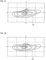
7A ist eine Ansicht, die ein weiteres Lichtverteilungsmuster zeigt, das durch den Fahrzeug-Scheinwerfer des Vergleichsbeispiels erzeugt wird.7A is a view showing another light distribution pattern produced by the vehicle headlamp of the comparative example. -
7B ist eine Ansicht, die ein weiteres Lichtverteilungsmuster zeigt, das durch den Fahrzeug-Scheinwerfer der vorliegenden Ausführungsform erzeugt wird.7B is a view showing another light distribution pattern produced by the vehicle headlamp of the present embodiment.
Ausführliche BeschreibungDetailed description
Es folgt eine Erläuterung einer bevorzugten Ausführungsform der Erfindung unter Bezugnahme auf die Zeichnungen. Identische oder äquivalente Bauteile, Teile und Vorgänge erhalten in jeder der Zeichnungen das gleiche Bezugszeichen, und gegebenenfalls wird auf wiederholte Erläuterung derselben verzichtet. Die Ausführungsformen sind beispielhaft und stellen keine Einschränkung der Erfindung dar, und nicht alle Merkmale und Kombinationen derselben in den Ausführungsformen sind notwendigerweise wesentlich für die Erfindung.A preferred embodiment of the invention will now be explained with reference to the drawings. Identical or equivalent components, parts and operations are given the same reference numerals in each of the drawings, and repeated explanations thereof will be omitted where appropriate. The embodiments are exemplary and do not constitute a limitation of the invention, and not all features and combinations thereof in the embodiments are necessarily essential to the invention.
Der Fahrzeug-Scheinwerfer 1 enthält vier Leuchteneinheiten 100. Die Leuchteneinheiten 100 sind im Inneren einer Leuchtenkammer aufgenommen, die von einem Leuchtenkörper (nicht dargestellt) mit einer Öffnung an der Fahrzeug-Vorderseite und einer transparenten Abdeckung (nicht dargestellt) gebildet wird, die so angebracht ist, dass sie die Öffnung des Leuchtenkörpers abdeckt. Die vier Leuchteneinheiten 100 sind in einer Reihe in der Querrichtung des Scheinwerfers angeordnet, und benachbarte Einheiten sind miteinander gekoppelt, so dass eine integrale Struktur entsteht. Die am weitesten rechts (Fahrzeug-Außenseite) positionierte Leuchteneinheit 100 dient als eine Nebelleuchte. Die am weitesten links (Fahrzeug-Innenseite) positionierte Leuchteneinheit 100 dient als eine Kurvenleuchte. Die zwei Leuchteneinheiten 100 dazwischen dienen als Nebelleuchten und Kurvenleuchten. Es ist anzumerken, dass keine speziellen Einschränkungen hinsichtlich der Anzahl, Anordnung und Funktion der Leuchteneinheiten 100 gelten.The vehicle headlamp 1 includes four
Die Leuchteneinheiten 100 sind mit Trageteil-Kopplungsabschnitten 2 versehen. Trageteile (nicht dargestellt), die aus dem Leuchtenkörper heraus vorstehen, sind mit den Trageteil-Kopplungsabschnitten 2 gekoppelt. Damit wird die Leuchteneinheit 100 an dem Leuchtenkörper angebracht.The
Bei jeder der Leuchteneinheiten 100 handelt es sich um eine bekannte Parabol-Leuchteneinheit, und sie enthält einen Abschnitt 120 zur Installation eines Elementes, ein lichtemittierendes Element 140 sowie einen Reflektor 160.Each of the
Die Abschnitte 120 zur Installation eines Elementes sind im Wesentlichen plattenförmige Teile, die die lichtemittierenden Elemente 140 tragen. Bei dem Fahrzeug-Scheinwerfer 1 der Ausführungsform haben die vier Leuchteneinheiten 100, wie oben beschrieben eine Konstruktion, bei der sie miteinander gekoppelt sind. Die Abschnitte 120 zur Installation von Elementen jeder der Leuchteneinheiten 100 sind daher so miteinander gekoppelt, dass die Abschnitte 120 zur Installation von Elementen einen aus einem Stück bestehenden plattenförmigen Sockel bilden.The
Die Abschnitte 120 zur Installation von Elementen enthalten eine Anbringungsfläche 122, an der die lichtemittierenden Elemente 140 angebracht sind. Die Abschnitte 120 zur Installation von Elementen sind so angeordnet, dass die Anbringungsfläche 122 in dem Scheinwerfer im Wesentlichen nach unten gerichtet ist, und sie sind an den Reflektoren 160 befestigt. Die Anbringungsfläche 122 ist so geneigt, dass sich jedes Ende in der Querrichtung des Scheinwerfers an einer anderen Höhenposition befindet. Das heißt, die Anbringungsfläche 122 ist in Bezug auf eine horizontale Ebene um eine Achse herum geneigt, die parallel zu der Scheinwerfer-Längsachse ist und durch die Anbringungsfläche hindurch verläuft. Die unterbrochene Linie in
Die lichtemittierenden Elemente 140 werden beispielsweise durch Halbleiter-Lichtemissionsvorrichtungen, wie beispielsweise LED, gebildet. Jedes der lichtemittierenden Elemente 140 hat eine rechteckig geformte lichtemittierende Fläche 142. Die lichtemittierenden Elemente 140 können eine Konstruktion haben, bei der eine Halbleiter-Lichtemissionsvorrichtung und ein Leuchtstoff kombiniert werden, der die Wellenlänge von Licht von der Halbleiter-Lichtemissionsvorrichtung umwandelt. Die lichtemittierenden Elemente 140 sind so an der Anbringungsfläche 122 angebracht, dass die lichtemittierenden Flächen 142 derselben in dem Scheinwerfer im Wesentlichen nach unten gewandt sind. Die lichtemittierenden Flächen 142 erstrecken sich in dem Zustand, in dem die lichtemittierenden Elemente 140 an der Anbringungsfläche 122 angebracht sind, parallel zu der Anbringungsfläche 122.The light-emitting
Die Reflektoren 160 enthalten jeweils eine reflektierende Fläche 162, die Licht von dem lichtemittierenden Element 140 zur Vorderseite des Scheinwerfers reflektiert. Die Reflektoren 160 projizieren ein Lichtmuster Pa, das der Form der lichtemittierenden Fläche 142 des lichtemittierenden Elementes 140 entspricht, zur Vorderseite des Scheinwerfers (siehe
Es folgt eine ausführliche Erläuterung hinsichtlich der Ausrichtung der lichtemittierenden Elemente 140 an der Anbringungsfläche 122.
Als Alternative dazu kann die Bezugsposition 240 die Position sein, die von dem lichtemittierenden Element 140 eingenommen wird, wenn, von einem Zustand ausgehend, in dem die Anbringungsfläche 122 parallel zu der horizontalen Ebene ist und sich das lichtemittierende Element 140 in einer Ausrichtung (einer Position) befindet, die entsprechend der Form eines zu erzeugenden Lichtverteilungsmusters bestimmt wird, die Anbringungsfläche 122 geneigt wird, um die Höhenposition der jeweiligen Enden 122L, 122R der Anbringungsfläche 122 zu ändern (so dass sich jedes der Enden 122L, 122R der Anbringungsfläche 122 in einer anderen Höhe befindet), während die Ausrichtung des lichtemittierenden Elementes 140 aufrechterhalten wird.Alternatively, the
Jedes lichtemittierende Element 140 ist so an der Anbringungsfläche 122 angebracht, dass sich die lichtemittierende Fläche 142 an einer Position befindet, die um eine Bezugsachse N herum in Bezug auf die Bezugsposition 240 verdreht ist. Die Bezugsachse N ist rechtwinklig zu der lichtemittierenden Fläche 242, wenn sich das lichtemittierende Element 140 an der Bezugsposition 240 befindet. In der vorliegenden Ausführungsform ist die Bezugsachse N eine Achse, die durch die Mitte der lichtemittierenden Fläche 142 hindurch verläuft. Das Maß der Verdrehung des lichtemittierenden Elementes 140 wird entsprechend der Neigung der Anbringungsfläche 142 und der Form des zu erzeugenden Lichtverteilungsmusters angepasst. Wenn beispielsweise die Anbringungsfläche 122 um 5° in Bezug auf die horizontale Ebene geneigt ist, kann das Maß der Verdrehung des lichtemittierenden Elementes 140 hinsichtlich der Bezugsposition 240 15° betragen.Each light-emitting
Im Folgenden werden Unterschiede zwischen dem Lichtverteilungsmuster, das durch den Fahrzeug-Scheinwerfer 1 erzeugt wird, die mit der oben beschriebenen Konstruktion versehen ist, und dem Lichtverteilungsmuster erläutert, dass durch einen Fahrzeug-Scheinwerfer eines Vergleichsbeispiels erzeugt wird. Bei dem Fahrzeug-Scheinwerfer des Vergleichsbeispiels ist eine Anbringungsfläche so geneigt, dass sich jedes Ende in der Querrichtung des Scheinwerfers an einer anderen Höhe befindet und sich die lichtemittierenden Elemente an der Bezugsposition 240 befinden.Next, differences between the light distribution pattern produced by the vehicle headlamp 1 provided with the above-described construction and the light distribution pattern produced by a vehicle headlamp of a comparative example will be explained. In the vehicle headlamp of the comparative example, a mounting surface is inclined so that each end in the transverse direction of the headlamp is at a different height and the light-emitting elements are located at the
Die Reflektoren 160 des Fahrzeug-Scheinwerfers 1 der vorliegenden Ausführungsform reflektieren, wie in
Bei dem Fahrzeug-Scheinwerfer des Vergleichsbeispiels, bei der die Anbringungsfläche hinsichtlich der horizontalen Ebene geneigt ist und sich die lichtemittierenden Elemente an der Bezugsposition befinden, ist, wie in
Jedoch befinden sich, wie in
Bei dem Fahrzeug-Scheinwerfer des Vergleichsbeispiels wird, wie in
Bei dem Fahrzeug-Scheinwerfer 1 der vorliegenden Ausführungsform ist, wie oben beschrieben, die Anbringungsfläche 122 zum Anbringen des lichtemittierenden Elementes 140 so geneigt, dass sich die Höhenpositionen jedes Endes 122L, 122R in der Querrichtung des Scheinwerfers voneinander unterscheiden. Die lichtemittierenden Elemente 140 sind an Positionen angeordnet, die gegenüber der Bezugsposition 240 verdreht sind, an der die zwei Seiten 242a, 242c der lichtemittierenden Fläche 242 parallel zu der Scheinwerfer-Längsachse sind und die zwei anderen Seiten 242b, 242d senkrecht zu der Scheinwerfer-Längsachse sind. Als Alternative dazu können die lichtemittierenden Elemente 140 an Positionen angeordnet sein, die hinsichtlich der Bezugspositionen 240 verdreht sind, die von den lichtemittierenden Elementen 140 eingenommene Positionen sind, wenn die Ausrichtung der lichtemittierenden Elemente 140 entsprechend der Form des Lichtverteilungsmusters bestimmt wird und sich die Anbringungsfläche 122 in einem horizontalen Zustand befindet und dann die Anbringungsfläche 122 geneigt wird und dabei die Ausrichtung der lichtemittierenden Elemente 140 aufrechterhalten wird. Eine Verringerung der Genauigkeit bei der Ausbildung eines Lichtverteilungsmusters aufgrund von Neigen der Anbringungsfläche 122 in einem Zustand, in dem der Fahrzeug-Scheinwerfer an dem Fahrzeug angebracht ist, kann damit verhindert werden.In the vehicle headlamp 1 of the present embodiment, as described above, the mounting
Der Reflektor 160 reflektiert das Licht des lichtemittierenden Elementes 140 so, dass die eine Seite der lichtemittierenden Fläche 142 wenigstens einen Teil der Hell-Dunkel-Grenze CL des Lichtverteilungsmusters P1 bildet. Des Weiteren reflektieren die Reflektoren 160 Licht so, dass jeweils eine Seite der mehreren lichtemittierenden Flächen 142 so ausgerichtet ist, dass die Hell-Dunkel-Grenze CL gebildet wird. Die Hell-Dunkel-Grenze CL kann dementsprechend selbst dann mit hoher Genauigkeit ausgebildet werden, wenn die Anbringungsfläche 122 geneigt ist.The
Die Erfindung ist nicht auf die oben beschriebene Ausführungsform beschränkt, und der Schutzumfang der Erfindung schließt Ausführungsformen ein, auf die verschiedene Abwandlungen, wie beispielsweise konstruktive Abwandlungen, angewendet werden, die unter Inanspruchnahme der Sachkenntnis eines Fachmanns angewendet werden können. Eine neue Ausführungsform, die sich ergibt, indem die oben beschriebene Ausführungsform mit der folgenden Abwandlung kombiniert wird, weist die kombinierten vorteilhaften Effekte der Ausführungsform und der Abwandlung auf.The invention is not limited to the embodiment described above, and the scope of the invention includes embodiments to which various modifications such as structural modifications are applied, which can be applied using the skill of a person skilled in the art. A new embodiment obtained by combining the embodiment described above with the following modification has the combined advantageous effects of the embodiment and the modification.
In der oben beschriebenen Ausführungsform sind alle vier lichtemittierenden Elemente 140 an Positionen angeordnet, die hinsichtlich der Bezugsposition 240 verdreht sind. Dies stellt jedoch keine spezielle Einschränkung dar, und der vorteilhafte Effekt dahingehend, dass eine Verringerung der Genauigkeit bei der Ausbildung des Lichtverteilungsmusters verhindert wird, die durch Neigen der Anbringungsfläche 122 bewirkt wird, kann erzielt werden, sofern wenigstens eines der lichtemittierenden Elemente 140 in einer verdrehten Position angeordnet ist.In the embodiment described above, all four light-emitting
Claims (4)
Applications Claiming Priority (2)
| Application Number | Priority Date | Filing Date | Title |
|---|---|---|---|
| JP2014-034360 | 2014-02-25 | ||
| JP2014034360A JP6271292B2 (en) | 2014-02-25 | 2014-02-25 | Vehicle lighting |
Publications (2)
| Publication Number | Publication Date |
|---|---|
| DE102015203362A1 DE102015203362A1 (en) | 2015-08-27 |
| DE102015203362B4 true DE102015203362B4 (en) | 2024-06-06 |
Family
ID=53782722
Family Applications (1)
| Application Number | Title | Priority Date | Filing Date |
|---|---|---|---|
| DE102015203362.7A Expired - Fee Related DE102015203362B4 (en) | 2014-02-25 | 2015-02-25 | Vehicle headlights |
Country Status (6)
| Country | Link |
|---|---|
| US (1) | US9243772B2 (en) |
| JP (1) | JP6271292B2 (en) |
| KR (1) | KR101726487B1 (en) |
| CN (1) | CN104864337B (en) |
| DE (1) | DE102015203362B4 (en) |
| FR (1) | FR3017925B1 (en) |
Families Citing this family (6)
| Publication number | Priority date | Publication date | Assignee | Title |
|---|---|---|---|---|
| US11124116B2 (en) * | 2014-12-12 | 2021-09-21 | Serge B. HOYDA | System and process for viewing in blind spots |
| US10046703B2 (en) | 2014-12-12 | 2018-08-14 | Serge B. HOYDA | System and process for viewing in blind spots |
| US11518309B2 (en) | 2014-12-12 | 2022-12-06 | Serge Hoyda LLC | System and process for viewing in blind spots |
| CN106969306B (en) * | 2016-01-13 | 2019-10-22 | 市光法雷奥(佛山)汽车照明系统有限公司 | The luminous vertical type lighting device in side for motor vehicles |
| US10704757B2 (en) * | 2018-10-19 | 2020-07-07 | Valeo North America, Inc. | Lighting unit for automotive headlamp |
| CN115688284B (en) * | 2022-11-07 | 2025-07-22 | 广汽丰田汽车有限公司 | Car lamp installation position acquisition method, device, equipment and storage medium |
Citations (3)
| Publication number | Priority date | Publication date | Assignee | Title |
|---|---|---|---|---|
| EP2103866A2 (en) | 2008-03-19 | 2009-09-23 | Honda Motor Co., Ltd. | Vehicle light |
| JP2011082117A (en) | 2009-10-09 | 2011-04-21 | Koito Mfg Co Ltd | Vehicle headlight device |
| JP2013197070A (en) | 2012-03-23 | 2013-09-30 | Ichikoh Ind Ltd | Vehicle lamp |
Family Cites Families (12)
| Publication number | Priority date | Publication date | Assignee | Title |
|---|---|---|---|---|
| DE20100918U1 (en) * | 2001-01-18 | 2001-03-22 | Reitter & Schefenacker GmbH & Co. KG, 73730 Esslingen | Lights, in particular signal lights, for motor vehicles |
| RU2190153C1 (en) * | 2001-01-23 | 2002-09-27 | Открытое акционерное общество "АВТОВАЗ" | Vehicles signal light |
| JP4459702B2 (en) * | 2004-04-27 | 2010-04-28 | 株式会社小糸製作所 | Lighting fixtures for vehicles |
| JP4624257B2 (en) * | 2005-12-28 | 2011-02-02 | 株式会社小糸製作所 | Vehicle lighting |
| JP4707189B2 (en) * | 2006-06-02 | 2011-06-22 | 株式会社小糸製作所 | Vehicle lamp |
| JP2007335311A (en) | 2006-06-16 | 2007-12-27 | Koito Mfg Co Ltd | Vehicle lamp |
| JP4995748B2 (en) * | 2008-01-29 | 2012-08-08 | 株式会社小糸製作所 | Vehicle headlamp device and control method for vehicle headlamp device |
| JP5405043B2 (en) * | 2008-04-22 | 2014-02-05 | 株式会社小糸製作所 | Vehicle lighting |
| JP5722691B2 (en) * | 2011-04-22 | 2015-05-27 | 株式会社小糸製作所 | Vehicle headlamp |
| KR101273076B1 (en) | 2011-09-29 | 2013-06-10 | 에스엘 주식회사 | Double reflecting structure |
| FR2984457B1 (en) * | 2011-12-19 | 2023-08-11 | Valeo Vision | LIGHTING MODULE COMPRISING AT LEAST TWO LIGHT SOURCES INSTALLED SUBSTANTIALLY ORTHOGONALLY |
| JP2013246944A (en) | 2012-05-24 | 2013-12-09 | Ichikoh Ind Ltd | Vehicle headlight |
-
2014
- 2014-02-25 JP JP2014034360A patent/JP6271292B2/en active Active
-
2015
- 2015-01-19 KR KR1020150008479A patent/KR101726487B1/en not_active Expired - Fee Related
- 2015-02-03 US US14/612,940 patent/US9243772B2/en active Active
- 2015-02-15 CN CN201510082344.6A patent/CN104864337B/en not_active Expired - Fee Related
- 2015-02-25 FR FR1551591A patent/FR3017925B1/en not_active Expired - Fee Related
- 2015-02-25 DE DE102015203362.7A patent/DE102015203362B4/en not_active Expired - Fee Related
Patent Citations (3)
| Publication number | Priority date | Publication date | Assignee | Title |
|---|---|---|---|---|
| EP2103866A2 (en) | 2008-03-19 | 2009-09-23 | Honda Motor Co., Ltd. | Vehicle light |
| JP2011082117A (en) | 2009-10-09 | 2011-04-21 | Koito Mfg Co Ltd | Vehicle headlight device |
| JP2013197070A (en) | 2012-03-23 | 2013-09-30 | Ichikoh Ind Ltd | Vehicle lamp |
Also Published As
| Publication number | Publication date |
|---|---|
| JP6271292B2 (en) | 2018-01-31 |
| US20150241010A1 (en) | 2015-08-27 |
| CN104864337B (en) | 2017-09-29 |
| JP2015159088A (en) | 2015-09-03 |
| FR3017925B1 (en) | 2017-11-24 |
| CN104864337A (en) | 2015-08-26 |
| FR3017925A1 (en) | 2015-08-28 |
| KR101726487B1 (en) | 2017-04-12 |
| US9243772B2 (en) | 2016-01-26 |
| KR20150100495A (en) | 2015-09-02 |
| DE102015203362A1 (en) | 2015-08-27 |
Similar Documents
| Publication | Publication Date | Title |
|---|---|---|
| DE102020213531B4 (en) | A lamp for a vehicle, comprising an entrance lens unit, an exit lens unit, and a shade unit interposed between them | |
| DE102015203362B4 (en) | Vehicle headlights | |
| DE102017219953B4 (en) | VEHICLE LIGHT | |
| DE102014215759B4 (en) | VEHICLE LAMP HAVING A HIGH BEAM REFLECTOR UNIT AND A LOW BEAM REFLECTOR UNIT, BOTH CONSISTING OF REFLECTORS THAT REFLECT LIGHT FROM ANGLED LIGHT SOURCES | |
| DE10340432B4 (en) | vehicle headlights | |
| DE112013003050B4 (en) | Vehicle light and method for controlling the same | |
| DE102007024962B4 (en) | vehicle light | |
| DE102014219156A1 (en) | Vehicle Front Light | |
| DE102007017756B4 (en) | lighting device | |
| DE102017208984A1 (en) | vehicle light | |
| DE102004053302A1 (en) | vehicle headlights | |
| DE102017202486A1 (en) | vehicle lamp | |
| EP2984396B1 (en) | Lamp unit comprising a shield having at least one light window | |
| DE102010009640A1 (en) | Headlamp with an LED reflection system with fog light and daytime running light function | |
| DE102010021937A1 (en) | LED projection module for a vehicle headlight | |
| DE10316069A1 (en) | vehicle headlights | |
| DE102016201977A1 (en) | vehicle light | |
| DE102005014448B4 (en) | vehicle headlights | |
| DE202015010030U1 (en) | Light module for lighting and/or signalling a motor vehicle | |
| DE102011053225A1 (en) | Headlight for a vehicle | |
| DE102012101919A1 (en) | Light source for vehicle has two lighting units, where each lighting unit is provided with multiple light emitting diode chips, while lighting units are separated from each other to emit light on reflector in switchable manner | |
| DE202015102267U1 (en) | Headlamp assembly with multiple high aspect ratio lenses | |
| DE102019107532A1 (en) | LIGHTING DEVICE AND MOTOR BODY | |
| DE202017001946U1 (en) | Headlamp with an optical system with static matrix cornering light | |
| DE202017001379U1 (en) | Headlamp with a modular projection module to improve the illumination intensity |
Legal Events
| Date | Code | Title | Description |
|---|---|---|---|
| R079 | Amendment of ipc main class |
Free format text: PREVIOUS MAIN CLASS: F21S0008120000 Ipc: F21S0041000000 |
|
| R012 | Request for examination validly filed | ||
| R079 | Amendment of ipc main class |
Free format text: PREVIOUS MAIN CLASS: F21S0041000000 Ipc: F21S0041190000 |
|
| R016 | Response to examination communication | ||
| R018 | Grant decision by examination section/examining division | ||
| R020 | Patent grant now final | ||
| R119 | Application deemed withdrawn, or ip right lapsed, due to non-payment of renewal fee |