DE102015110788A1 - Connector connecting structure - Google Patents
Connector connecting structure Download PDFInfo
- Publication number
- DE102015110788A1 DE102015110788A1 DE102015110788.0A DE102015110788A DE102015110788A1 DE 102015110788 A1 DE102015110788 A1 DE 102015110788A1 DE 102015110788 A DE102015110788 A DE 102015110788A DE 102015110788 A1 DE102015110788 A1 DE 102015110788A1
- Authority
- DE
- Germany
- Prior art keywords
- terminal
- section
- bolt
- connection
- bolt tightening
- Prior art date
- Legal status (The legal status is an assumption and is not a legal conclusion. Google has not performed a legal analysis and makes no representation as to the accuracy of the status listed.)
- Granted
Links
Images


Classifications
-
- H—ELECTRICITY
- H01—ELECTRIC ELEMENTS
- H01R—ELECTRICALLY-CONDUCTIVE CONNECTIONS; STRUCTURAL ASSOCIATIONS OF A PLURALITY OF MUTUALLY-INSULATED ELECTRICAL CONNECTING ELEMENTS; COUPLING DEVICES; CURRENT COLLECTORS
- H01R4/00—Electrically-conductive connections between two or more conductive members in direct contact, i.e. touching one another; Means for effecting or maintaining such contact; Electrically-conductive connections having two or more spaced connecting locations for conductors and using contact members penetrating insulation
- H01R4/28—Clamped connections, spring connections
- H01R4/30—Clamped connections, spring connections utilising a screw or nut clamping member
- H01R4/34—Conductive members located under head of screw
-
- H—ELECTRICITY
- H01—ELECTRIC ELEMENTS
- H01R—ELECTRICALLY-CONDUCTIVE CONNECTIONS; STRUCTURAL ASSOCIATIONS OF A PLURALITY OF MUTUALLY-INSULATED ELECTRICAL CONNECTING ELEMENTS; COUPLING DEVICES; CURRENT COLLECTORS
- H01R4/00—Electrically-conductive connections between two or more conductive members in direct contact, i.e. touching one another; Means for effecting or maintaining such contact; Electrically-conductive connections having two or more spaced connecting locations for conductors and using contact members penetrating insulation
- H01R4/10—Electrically-conductive connections between two or more conductive members in direct contact, i.e. touching one another; Means for effecting or maintaining such contact; Electrically-conductive connections having two or more spaced connecting locations for conductors and using contact members penetrating insulation effected solely by twisting, wrapping, bending, crimping, or other permanent deformation
- H01R4/18—Electrically-conductive connections between two or more conductive members in direct contact, i.e. touching one another; Means for effecting or maintaining such contact; Electrically-conductive connections having two or more spaced connecting locations for conductors and using contact members penetrating insulation effected solely by twisting, wrapping, bending, crimping, or other permanent deformation by crimping
-
- H—ELECTRICITY
- H01—ELECTRIC ELEMENTS
- H01R—ELECTRICALLY-CONDUCTIVE CONNECTIONS; STRUCTURAL ASSOCIATIONS OF A PLURALITY OF MUTUALLY-INSULATED ELECTRICAL CONNECTING ELEMENTS; COUPLING DEVICES; CURRENT COLLECTORS
- H01R11/00—Individual connecting elements providing two or more spaced connecting locations for conductive members which are, or may be, thereby interconnected, e.g. end pieces for wires or cables supported by the wire or cable and having means for facilitating electrical connection to some other wire, terminal, or conductive member, blocks of binding posts
- H01R11/11—End pieces or tapping pieces for wires, supported by the wire and for facilitating electrical connection to some other wire, terminal or conductive member
- H01R11/12—End pieces terminating in an eye, hook, or fork
-
- H—ELECTRICITY
- H01—ELECTRIC ELEMENTS
- H01R—ELECTRICALLY-CONDUCTIVE CONNECTIONS; STRUCTURAL ASSOCIATIONS OF A PLURALITY OF MUTUALLY-INSULATED ELECTRICAL CONNECTING ELEMENTS; COUPLING DEVICES; CURRENT COLLECTORS
- H01R4/00—Electrically-conductive connections between two or more conductive members in direct contact, i.e. touching one another; Means for effecting or maintaining such contact; Electrically-conductive connections having two or more spaced connecting locations for conductors and using contact members penetrating insulation
- H01R4/10—Electrically-conductive connections between two or more conductive members in direct contact, i.e. touching one another; Means for effecting or maintaining such contact; Electrically-conductive connections having two or more spaced connecting locations for conductors and using contact members penetrating insulation effected solely by twisting, wrapping, bending, crimping, or other permanent deformation
- H01R4/18—Electrically-conductive connections between two or more conductive members in direct contact, i.e. touching one another; Means for effecting or maintaining such contact; Electrically-conductive connections having two or more spaced connecting locations for conductors and using contact members penetrating insulation effected solely by twisting, wrapping, bending, crimping, or other permanent deformation by crimping
- H01R4/183—Electrically-conductive connections between two or more conductive members in direct contact, i.e. touching one another; Means for effecting or maintaining such contact; Electrically-conductive connections having two or more spaced connecting locations for conductors and using contact members penetrating insulation effected solely by twisting, wrapping, bending, crimping, or other permanent deformation by crimping for cylindrical elongated bodies, e.g. cables having circular cross-section
- H01R4/184—Electrically-conductive connections between two or more conductive members in direct contact, i.e. touching one another; Means for effecting or maintaining such contact; Electrically-conductive connections having two or more spaced connecting locations for conductors and using contact members penetrating insulation effected solely by twisting, wrapping, bending, crimping, or other permanent deformation by crimping for cylindrical elongated bodies, e.g. cables having circular cross-section comprising a U-shaped wire-receiving portion
Landscapes
- Connections By Means Of Piercing Elements, Nuts, Or Screws (AREA)
- Connection Or Junction Boxes (AREA)
Abstract
Es wird eine Anschlussverbindungsstruktur (10) vorgeschlagen, bei der ein Bolzenfestziehanschluss (66) auf einen Anschlussanbringungsabschnitt (13) gesetzt und mit einem Verbindungsbolzen (78) befestigt wird, der an einer Mutter (36) des Anschlussanbringungsabschnitts (13) festgezogen wird. Der Anschlussanbringungsabschnitt (13) ist mit einem Verlagerungsbegrenzungsabschnitt (32) versehen. Wenn der Bolzenfestziehanschluss (66) auf einen Anschlussanbringungsabschnitt (13) gesetzt und in einer ordnungsgemäßen Anbringposition angeordnet ist, in der ein Bolzeneinführloch (74) und ein Gewindeloch (38) an derselben Mittelachse ausgerichtet sind, ist der Bolzenfestziehanschluss (66) so ausgelegt, dass er nicht von dem Verlagerungsbegrenzungsabschnitt (32) behindert wird. Wenn der Bolzenfestziehanschluss (66) sich aus der ordnungsgemäßen Anbringposition verlagert, ist der Bolzenfestziehanschluss (66) so ausgelegt, dass er von dem Verlagerungsbegrenzungsabschnitt (32) behindert wird, der die Verlagerung aus der ordnungsgemäßen Anbringposition begrenzt.A terminal connection structure (10) is proposed in which a bolt tightening terminal (66) is set on a terminal attachment portion (13) and fastened with a connection bolt (78) tightened to a nut (36) of the terminal attachment portion (13). The terminal attaching portion (13) is provided with a displacement restricting portion (32). When the bolt tightening terminal (66) is set on a terminal attachment portion (13) and disposed in a proper mounting position in which a bolt insertion hole (74) and a threaded hole (38) are aligned on the same center axis, the bolt tightening terminal (66) is designed such that he is not hindered by the displacement limiting section (32). When the bolt tightening terminal (66) shifts from the proper mounting position, the bolt tightening terminal (66) is designed to be obstructed by the displacement restricting portion (32) that restricts the displacement from the proper mounting position.
Description
TECHNISCHES GEBIET TECHNICAL AREA
Die vorliegende Erfindung betrifft eine Anschlussverbindungsstruktur zum Befestigen bzw. Festziehen eines Bolzenfestziehsanschlusses, der sich an einem Ende eines Elektrokabels befindet, an einem Anschlussanbringungsabschnitt, der an einem Stromkreis bereitgestellt ist, mit einem Bolzen. The present invention relates to a terminal connection structure for fixing a bolt tightening terminal located at one end of an electric wire to a terminal attachment portion provided on a circuit with a bolt.
TECHNISCHER HINTERGRUND TECHNICAL BACKGROUND
Stromkreise wie beispielsweise Stromanschlusskästen und Sicherungselemente für den Einsatz in der Fahrzeugelektrik sind herkömmlich mit einem Anschlussanbringungsabschnitt versehen, an dem Leitungselemente wie Sammelschienen angebracht werden, die einen Teil des Stromkreises bilden. Ein solcher herkömmlicher Stromkreis benutzt eine Anschlussverbindungsstruktur, bei der der Stromkreis mit einem Elektrokabel elektrisch leitend verbunden wird, indem ein Bolzenfestziehanschluss, der sich an einem Ende eines Elektrokabels befindet, mit einem Bolzen an dem Anschlussanbringungsabschnitt befestigt wird.
In den letzten Jahren hat sich aufgrund der steigenden Anzahl der in Fahrzeugen installierten elektrischen Komponenten und der Nachfrage nach kleineren Fahrzeugen der für Stromkreise verfügbare Platz immer mehr verringert. Dementsprechend ist es manchmal schwierig, einen Stiftbolzen mit großem Überstand wie in
Bei der in
Eine denkbare Lösung könnte darin bestehen, eine Struktur einzusetzen, bei der der Bolzenfestziehanschluss in den Anschlussanbringungsabschnitt eingepasst wird, bevor sie mit einem Verbindungsbolzen befestigt wird, da dies die Ausrichtung zwischen dem Bolzenfestziehanschluss und dem Anschlussanbringungsabschnitt aufrechterhalten kann. Dabei wäre jedoch eine große Kraft zum Anbringen des Bolzenfestziehanschlusses in dem Anschlussanbringungsabschnitt erforderlich, was wiederum möglicherweise die Arbeitseffizienz beeinträchtigt. A conceivable solution could be to use a structure in which the bolt tightening terminal is fitted in the terminal mounting portion before being fastened with a connecting bolt, as this can maintain alignment between the bolt tightening terminal and the terminal mounting portion. However, a large force would be required for attaching the bolt tightening terminal in the terminal attachment portion, which in turn may possibly affect the working efficiency.
ÜBERBLICK ÜBER DIE ERFINDUNG OVERVIEW OF THE INVENTION
Die vorliegende Erfindung entstand angesichts der oben beschriebenen Umstände und löst die Aufgabe durch eine neuartige Anschlussverbindungsstruktur, bei der sich ein Bolzenfestziehanschluss (also z.B. ein durch einen Bolzen festzuziehenden oder festgezogener Anschluss) einfach auf einen Anschlussanbringungsabschnitt setzen lässt, in dem eine Mutter angeordnet ist, und sich der Bolzenfestziehanschluss, bevor er an dem Anschlussanbringungsabschnitt befestigt wird, auch in der richtigen Position an dem Anschlussanbringungsabschnitt halten lässt. The present invention has been made in view of the above-described circumstances, and achieves the object by a novel terminal connection structure in which a bolt tightening terminal (eg, a terminal to be tightened or tightened by a bolt) can be easily set to a terminal mounting portion in which a nut is disposed The bolt tightening terminal, before it is attached to the terminal attachment portion, can also be held in the correct position on the terminal attachment portion.
Verschiedene Aspekte der vorliegenden Erfindung zum Lösen der oben genannten Aufgabe werden nun nachfolgend beschrieben. Es sei angemerkt, dass die in den diversen Ausführungsformen benutzten Komponenten in beliebiger Kombination benutzt werden können. Various aspects of the present invention for achieving the above object will now be described below. It should be noted that the components used in the various embodiments can be used in any combination.
Der erste Aspekt der vorliegenden Erfindung stellt eine Anschlussverbindungsstruktur (z.B. eine Klemmenanschlussstruktur) bereit, die aufweist: einen Anschlussanbringungsabschnitt (also einen Abschnitt an dem ein Anschluss anbringbar ist), der an einem Stromkreis bereitgestellt ist, eine Mutter, die an (z.B. auf oder in) dem Anschlussanbringungsabschnitt angeordnet und in der ein Gewindeloch ausgebildet ist, ein Bolzenfestziehanschluss, der an einem Elektrokabelende bereitgestellt ist und in der ein Bolzeneinführloch ausgebildet ist, und einen Verbindungsbolzen, wobei der Bolzenfestziehanschluss auf den Anschlussanbringungsabschnitt gesetzt und durch Durchstecken des Verbindungsbolzens durch das Bolzeneinführloch des Bolzenfestziehanschlusses und Festziehen des Verbindungsbolzens an dem Gewindeloch der Mutter an dem Anschlussanbringungsabschnitt befestigt wird: wobei der Anschlussanbringungsabschnitt mit einem Verlagerungsbegrenzungsabschnitt versehen ist, wobei der Bolzenfestziehanschluss so eingerichtet ist, dass er, wenn er auf den Anschlussanbringungsabschnitt gesetzt ist (bzw. darauf oder darin platziert ist) und in einer ordnungsgemäßen Anbringposition angeordnet ist, in der das Bolzeneinführloch und das Gewindeloch koaxial (also mit identischer Mittelachse) zueinander ausgerichtet sind, nicht von dem Verlagerungsbegrenzungsabschnitt behindert wird, und wobei der Bolzenfestziehanschluss so eingerichtet ist, dass er, wenn er auf den Anschlussanbringungsabschnitt gesetzt ist und sich aus der ordnungsgemäßen Anbringposition verlagert, von dem Verlagerungsbegrenzungsabschnitt behindert wird (z.B. an den Verlagerungsbegrenzungsabschnitt stößt), was die Verlagerung des Bolzenfestziehanschlusses aus der ordnungsgemäßen Anbringposition begrenzt. The first aspect of the present invention provides a terminal connection structure (eg, a terminal connection structure) comprising: a terminal attachment portion (that is, a terminal to which a terminal can be attached) provided on a circuit; a nut disposed on (eg, on or in) the terminal attachment portion and in which a threaded hole is formed, a bolt tightening terminal located at an electric wire end is provided and in which a Bolzeneinführloch is formed, and a connecting bolt, wherein the bolt tightening connection is set to the terminal attachment portion and by inserting the connecting bolt through the Bolzeneinführloch the bolt tightening terminal and tightening the connecting bolt to the threaded hole of the nut attached to the terminal mounting portion: wherein the terminal attachment portion with a Verlagerungsbegrenzungsabschnitt is provided, wherein the bolt tightening connection is arranged so that when it is placed on the terminal attachment portion (or placed on it or in it) and in a is arranged in the proper mounting position, in which the Bolzeneinführloch and the threaded hole coaxially (ie, with identical center axis) are aligned with each other, is not hindered by the Verlagerungsbegrenzungsabschnitt, and wherein the Bolzenfestziehanschluss is arranged so that when it is set to the terminal attachment portion and displaced from the proper mounting position, obstructed by the displacement restricting portion (eg abutting the displacement restricting portion), which limits the displacement of the bolt tightening terminal from the proper mounting position.
Gemäß diesem Aspekt behindern die Verlagerungsbegrenzungsabschnitte den Bolzenfestziehanschluss nicht, wenn diese in der ordnungsgemäßen Anbringposition am Anschlussanbringungsabschnitt angeordnet ist. Dementsprechend ermöglicht das Bereitstellen der Verlagerungsbegrenzungsabschnitte, dass der Bolzenfestziehanschluss einfach auf den Anschlussanbringungsabschnitt gesetzt wird, ohne dass das Anbringen des Bolzenfestziehanschlusses an dem Anschlussanbringungsabschnitt zusätzlichen Aufwand erfordert. According to this aspect, the displacement restricting portions do not hinder the bolt tightening terminal when it is arranged in the proper mounting position on the terminal attachment portion. Accordingly, the provision of the displacement restricting portions enables the bolt tightening terminal to be easily set on the terminal attaching portion without requiring the attachment of the bolt tightening terminal to the terminal attaching portion for extra effort.
Darüber hinaus behindern die Verlagerungsbegrenzungsabschnitte den Bolzenfestziehanschluss, um ihre Verlagerung zu begrenzen, wenn sich der Bolzenfestziehanschluss aus der ordnungsgemäßen Anbringposition am Anschlussanbringungsabschnitt verlagert. Dementsprechend verhindert dieser Aspekt der Erfindung Fehlausrichtung zwischen dem Gewindeloch der Mutter und dem Bolzeneinführloch des Bolzenfestziehanschlusses sowie das Herunterfallen des Bolzenfestziehanschlusses vom Anschlussanbringungsabschnitt. Folglich kann der Bolzenfestziehanschluss, obwohl die Mutter bei dieser Struktur in dem Anschlussanbringungsabschnitt angeordnet ist, an dem Anschlussanbringungsabschnitt an Ort und Stelle gehalten werden. Moreover, the displacement restricting portions hinder the bolt tightening terminal to limit its displacement when the bolt tightening terminal shifts from the proper mounting position to the terminal attaching portion. Accordingly, this aspect of the invention prevents misalignment between the threaded hole of the nut and the bolt insertion hole of the bolt tightening terminal and the drop of the bolt tightening terminal from the terminal mounting portion. Thus, although the nut is arranged in the terminal attachment portion in this structure, the pin tightening terminal can be held in place on the terminal attachment portion.
Der zweite Aspekt der vorliegenden Erfindung betrifft eine Anschlussverbindungsstruktur gemäß dem ersten Aspekt, wobei der Bolzenfestziehanschluss einen Anschlussplattenabschnitt, in dem das Bolzeneinführloch bereitgestellt ist und der auf den Anschlussanbringungsabschnitt gesetzt ist, einen Quetschabschnitt (Crimpabschnitt bzw. gecrimpten Abschnitt), der an das Elektrokabelende gequetscht bzw. gecrimpt ist, und einen Verbindungsabschnitt aufweist, der den Anschlussplattenabschnitt und den Quetschabschnitt verbindet, und das Breitenmaß des dem Anschlussplattenabschnitt zugewandten Teils des Verbindungsabschnitts größer ist als das Breitenmaß des dem Quetschabschnitt zugewandten Teils des Verbindungsabschnitts, und wobei der Anschlussanbringungsabschnitt ein Paar Verlagerungsbegrenzungsvorsprünge aufweist, die in Breitenrichtung an beiden Seiten des Verbindungsabschnitts angeordnet sind, das Maß des Abstands zwischen dem Paar Verlagerungsbegrenzungsabschnitte kleiner ist als das Breitenmaß des dem Anschlussplattenabschnitt zugewandten Teils des Verbindungsabschnitts und größer ist als der dem Quetschabschnitt zugewandte Teil des Verbindungsabschnitts, und das Paar Verlagerungsbegrenzungsvorsprünge den Verlagerungsbegrenzungsabschnitt bildet. The second aspect of the present invention relates to a terminal connecting structure according to the first aspect, wherein the bolt tightening terminal has a terminal plate portion in which the bolt insertion hole is provided and which is seated on the terminal mounting portion, crimping portion (crimping portion) crimped to the electric wire end is crimped, and has a connecting portion connecting the terminal plate portion and the crimping portion, and the width dimension of the connecting plate portion facing portion of the connecting portion is greater than the width dimension of the crimping portion facing portion of the connecting portion, and wherein the terminal attachment portion has a pair of displacement limiting projections are arranged in the width direction on both sides of the connecting portion, the measure of the distance between the pair of displacement limiting portions is smaller than there s width dimension of the connecting plate portion facing portion of the connecting portion and is larger than the pinching portion facing portion of the connecting portion, and the pair of displacement limiting projections forms the displacement limiting portion.
Gemäß diesem Aspekt wird, da das Maß des Abstands zwischen dem Paar Verlagerungsbegrenzungsvorspünge kleiner ist als das Breitenmaß des dem Anschlussplattenabschnitt zugewandten Teils des Verbindungsabschnitts, Zugkraft auf das Elektrokabel ausgeübt, und wenn sich der Bolzenfestziehanschluss in die Richtung verlagert, in der sich der Bolzenfestziehanschluss andernfalls vom Anschlussanbringungsabschnitt lösen würde, liegt der dem Anschlussplattenabschnitt zugewandte Teil des Verbindungsabschnitts an dem Paar Verlagerungsbegrenzungsvorsprünge an und wird von diesen behindert. Dies verhindert, dass sich der Bolzenfestziehanschluss vom Anschlussanbringungsabschnitt löst, und begrenzt gleichzeitig das Ausmaß der Verlagerung des Bolzenfestziehanschlusses aus der ordnungsgemäßen Anbringposition. According to this aspect, since the amount of the distance between the pair of displacement restriction projections is smaller than the width dimension of the portion of the connection portion facing the connection plate portion, tensile force is applied to the electric wire, and when the bolt tightening terminal shifts in the direction in which the bolt tightening terminal otherwise moves from the Solder terminal attachment portion, the terminal plate portion facing part of the connecting portion abuts the pair of Verlagerungsbegrenzungsvorsprünge and is hindered by these. This prevents the bolt tightening terminal from coming off the terminal attachment portion, and at the same time limits the amount of displacement of the bolt tightening terminal from the proper mounting position.
Da in Breitenrichtung beide Seiten des Verbindungsabschnitts an dem Paar Verlagerungsbegrenzungsvorsprünge anliegen und von diesen behindert werden, wird darüber hinaus vermieden, dass der Bolzenfestziehanschluss durch die beim Anliegen auftretende Gegenkraft verkippt wird, so dass der Anschlussplattenabschnitt in einer vorgegebenen Ausrichtung gehalten wird, in der er stabil auf den Anschlussanbringungsabschnitt gesetzt ist. Außerdem kommt der Effekt des Begrenzens der Verlagerung aufgrund des Anliegens zwischen dem Verbindungsabschnitt und dem Paar Verlagerungsbegrenzungsvorsprünge vorteilhafterweise unabhängig davon zur Geltung, ob der Anschlussplattenabschnitt des Bolzenfestziehanschlusses in Bezug zu dem Anschlussanbringungsabschnitt zum Quetschabschnitt hin anliegend verschoben oder in Bezug zu dem Anschlussanbringungsabschnitt kippend und sich von ihm lösend verlagert wird. In the width direction, since both sides of the connecting portion abut against and are obstructed by the pair of displacement restricting projections, it is further avoided that the bolt tightening terminal is tilted by the counterforce applied during the abutment, so that the terminal plate portion is maintained in a predetermined orientation in which it is stable is set to the terminal attachment portion. In addition, the effect of limiting the displacement occurs due to the abutment between the connecting portion and the pair Advantageously, displacement limiting protrusions are effective regardless of whether the terminal plate portion of the bolt tightening terminal is slidably displaced relative to the terminal mounting portion toward the crimping portion or tilted relative to the terminal mounting portion and displaced away therefrom.
Darüber hinaus ist das Maß des Abstands zwischen dem Paar Verlagerungsbegrenzungsvorsprünge größer gehalten als das Breitenmaß des dem Quetschabschnitt zugewandten Teils des Verbindungsabschnitts. Dementsprechend behindert das Paar Verlagerungsbegrenzungsvorsprünge, wenn der Bolzenfestziehanschluss in der ordnungsgemäßen Anbringposition auf dem Anschlussanbringungsabschnitt gesetzt ist, den Verbindungsabschnitt des Bolzenfestziehanschlusses nicht, so dass für das Zusammenbauen keine zusätzliche Kraft aufgewendet werden muss. Moreover, the amount of the distance between the pair of displacement restricting protrusions is made larger than the width dimension of the crimping portion facing portion of the connecting portion. Accordingly, when the bolt tightening terminal is set in the proper mounting position on the terminal attaching portion, the pair of displacement limiting protrusions does not obstruct the connecting portion of the bolt tightening terminal, so that no extra force has to be applied to the assembling.
Der dritte Aspekt der vorliegenden Erfindung betrifft eine Anschlussverbindungsstruktur gemäß dem zweiten Aspekt, wobei der Anschlussanbringungsabschnitt in Breitenrichtung an beiden Seiten des Verbindungsabschnitts mit einem Paar Anschlussdrehanschlagvorsprünge versehen ist und das Paar Verlagerungsbegrenzungsvorsprünge einstückig auf einander gegenüberliegenden Innenflächen des Paars Anschlussdrehanschlagvorsprünge bereitgestellt ist. The third aspect of the present invention relates to a terminal connection structure according to the second aspect, wherein the terminal attachment portion in the width direction is provided on both sides of the connection portion with a pair of terminal rotation stopper protrusions and the pair of displacement restriction projections are integrally provided on opposite inner surfaces of the pair of terminal rotation stopper projections.
Gemäß diesem Aspekt wird an dem Anschlussanbringungsabschnitt ein Paar Anschlussdrehanschlagvorsprünge bereitgestellt, um ein Verdrehen des Bolzenfestziehanschlusses beim Festziehen des Bolzens zu verhindern. Die Anschlussdrehanschlagvorsprünge vereinfachen das Bereitstellen des Paars Verlagerungsbegrenzungsvorsprünge, die das Paar Verlagerungsbegrenzungsabschnitte bilden, und gewährleisten gleichzeitig einen hohen Haltbarkeitsgrad der Verlagerungsbegrenzungsabschnitte. Insbesondere ist es durch Anpassen des Ausmaßes des Überstands der Verlagerungsbegrenzungsvorsprünge von den einander gegenüberliegenden Innenflächen der Anschlussdrehanschlagvorsprünge gemäß der Geometrie des Bolzenfestziehanschlusses möglich, die Verlagerungsbegrenzungsvorsprünge vorteilhafterweise passend zur konkreten Geometrie des Bolzenfestziehanschlusses zu einzurichten. According to this aspect, a pair of terminal rotation stopper protrusions are provided to the terminal attachment portion to prevent the bolt tightening terminal from rotating when the bolt is tightened. The terminal rotation stopper protrusions facilitate providing the pair of displacement restricting protrusions forming the pair of displacement restricting portions while ensuring a high durability of the displacement restricting portions. In particular, by adjusting the amount of protrusion of the displacement restricting protrusions from the opposed inner surfaces of the terminal rotational abutment projections according to the geometry of the bolt tightening terminal, it is possible to set the displacement restricting protrusions advantageously matching the concrete geometry of the bolt tightening terminal.
Gemäß der vorliegenden Erfindung wird der Bolzenfestziehanschluss von dem an dem Anschlussanbringungsabschnitt bereitgestellten Verlagerungsbegrenzungsabschnitt nicht behindert, wenn sie in der ordnungsgemäßen Anbringposition auf den Anschlussanbringungsabschnitt gesetzt ist. Auf diese Weise kann der Bolzenfestziehanschluss einfach auf den Anschlussanbringungsabschnitt gesetzt werden, ohne dass zusätzliche Kraft erforderlich ist. Andererseits wird der Bolzenfestziehanschluss von den Verlagerungsbegrenzungsabschnitten behindert, um ihre Verlagerung zu begrenzen, wenn sie sich aus der ordnungsgemäßen Anbringposition am Anschlussanbringungsabschnitt verlagert. Dementsprechend verhindert dieser Aspekt der Erfindung das Herunterfallen des Bolzenfestziehanschlusses vom Anschlussanbringungsabschnitt sowie die Verlagerung des Gewindelochs der Mutter gegenüber dem Bolzeneinführloch des Bolzenfestziehanschlusses. According to the present invention, the bolt tightening terminal is not obstructed by the displacement restricting portion provided on the terminal attaching portion when set to the terminal attaching portion in the proper mounting position. In this way, the bolt tightening terminal can be easily set on the terminal attachment portion without requiring additional force. On the other hand, the bolt tightening terminal is obstructed by the displacement restricting sections to limit its displacement as it shifts from the proper mounting position to the terminal mounting section. Accordingly, this aspect of the invention prevents the bolt tightening terminal from falling off the terminal attachment portion, and the displacement of the threaded hole of the nut against the bolt insertion hole of the bolt tightening terminal.
KURZE BESCHREIBUNG DER ZEICHNUNGEN BRIEF DESCRIPTION OF THE DRAWINGS
AUSFÜHRUNGSFORMEN DER ERFINDUNG EMBODIMENTS OF THE INVENTION
Bevorzugte Ausführungsformen der vorliegenden Erfindung werden nachfolgend unter spezieller Bezugnahme auf die beiliegenden Zeichnungen beschrieben. Preferred embodiments of the present invention are described below with particular reference to the accompanying drawings.
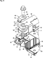
Die
Der Gehäusekörper
Darüber hinaus befindet sich in einer Ecke des Gehäusekörpers
An der Ecke des Gehäusekörpers
Darüber hinaus steht ein Verlagerungsbegrenzungsabschnitt, wie beispielsweise ein Verlagerungsbegrenzungsvorsprung
In dem unteren Wandabschnitt
In dem Anschlussanbringungsabschnitt
Wie in den
Darüber hinaus ist, wie in
Außerdem, ist wie in
Darüber hinaus ist an dem Anschlussanbringungsabschnitt
Wie in
Der Bolzenfestziehanschluss
Da der Bolzenfestziehanschluss
Da ferner der Abstand zwischen den Verlagerungsbegrenzungsvorsprüngen
Wie in
Auf diese Weise wird bei der Anschlussverbindungsstruktur
Da die Verlagerungsbegrenzungsvorsprünge
Bei dieser Ausführungsform ist darüber hinaus der Quetschabschnitt
Der Bolzenfestziehanschluss
Es wurde zwar eine Ausführungsform der vorliegenden Erfindung beschrieben, die vorliegende Erfindung ist jedoch nicht auf die konkrete Beschreibung der Ausführungsform eingeschränkt. So braucht beispielsweise das Behindern zwischen dem Verbindungsabschnitt des Bolzenfestziehanschlusses und den Verlagerungsbegrenzungsvorsprüngen nicht unbedingt wie bei der obigen Ausführungsform durch die verjüngte Form des Verbindungsabschnitts realisiert zu werden. Stattdessen können in den Seitenflächen des Verbindungsabschnitts Aussparungen ausgebildet sein, in denen die Verlagerungsbegrenzungsvorsprünge so aufgenommen werden, dass sie die Innenflächen der Aussparungen in Eingriff nehmen und behindern, wenn sich der Bolzenfestziehanschluss aus der ordnungsgemäßen Anbringposition heraus verlagert. Als weiteres Beispiel kann der Verbindungsabschnitt auch in einer abgestuften Form ausgebildet sein, deren Breitenmaß sich an der Stufe stufenförmig ändert, damit die Verlagerungsbegrenzungsabschnitte an der Stufe anliegen und diese behindern können. While an embodiment of the present invention has been described, the present invention is not limited to the concrete description of the embodiment. For example, the obstruction between the connecting portion of the bolt tightening terminal and the displacement restricting projections need not necessarily be realized by the tapered shape of the connecting portion as in the above embodiment. Instead, recesses may be formed in the side surfaces of the connecting portion in which the displacement limiting protrusions are received to engage and disengage the inner surfaces of the recesses as the bolt tightening terminal shifts out of the proper mounting position. As another example, the connecting portion may also be formed in a stepped shape whose width dimension changes stepwise at the step so that the displacement limiting portions abut the step and can hinder it.
Die Form des Bolzenfestziehanschlusses darf ferner nicht so interpretiert werden, dass sie auf die bei der obigen Ausführungsform beschriebene beschränkt ist. Bei dem Bolzenfestziehanschluss der obigen Ausführungsform handelt es sich zwar um einen L-förmige Anschluss mit einem gebogenen Verbindungsabschnitt, dieser kann jedoch beispielsweise, statt gebogen zu sein, auch linear verlaufen, so dass sich der Anschlussplattenabschnitt und der Quetschabschnitt in etwa in der gleichen Ebene befinden. Darüber hinaus ist der Bolzenfestziehanschluss nicht auf den Typ beschränkt, der dafür sorgt, dass der Verbindungsabschnitt von dem Verlagerungsbegrenzungsabschnitt behindert wird, wenn sich der Anschluss bzw. die Klemme aus ihrer ordnungsgemäßen Anbringposition heraus verlagert. Der Bolzenfestziehanschluss kann zum Beispiel auch so eingerichtet sein, dass sie bewirkt, dass der Anschlussplattenabschnitt oder der Quetschabschnitt von dem Verlagerungsbegrenzungsabschnitt behindert werden, wenn sich der Anschluss bzw. die Klemme aus ihrer ordnungsgemäßen Anbringposition heraus verlagert. Further, the shape of the bolt tightening terminal should not be interpreted as being limited to that described in the above embodiment. Although the bolt tightening terminal of the above embodiment is an L-shaped terminal having a bent connecting portion, for example, instead of being bent, it may be linear so that the terminal plate portion and the crimping portion are approximately in the same plane , Moreover, the bolt tightening terminal is not limited to the type that makes the connecting portion obstructed by the displacement restricting portion when the terminal is out out of their proper mounting position. For example, the bolt tightening terminal may be configured to cause the terminal plate portion or the crimping portion to be obstructed by the displacement restricting portion when the terminal shifts out of its proper mounting position.
Die Verlagerungsbegrenzungsvorsprünge können darüber hinaus separat von den Anschlussdrehanschlagvorsprüngen gebildet sein, und die Anschlussdrehanschlagvorsprünge sind für die vorliegende Erfindung nicht ausschlaggebend. Ferner müssen die Verlagerungsbegrenzungsvorsprünge, wenn sie einstückig mit den Anschlussdrehanschlagvorsprüngen ausgebildet sind, nicht an den proximalen Enden der Anschlussdrehanschlagvorsprünge ausgebildet sein. Die Verlagerungsbegrenzungsvorsprünge können beispielsweise an den gesamten gegenüberliegenden Innenflächen des Paars Anschlussdrehanschlagvorsprünge ausgebildet sein. Darüber hinaus können diverse Strukturen der Ausführungsform, wie die Mutter, die Sammelschienen, der Verbindungsanschluss, der Gehäusekörper, der den Anschlussanbringungsabschnitt aufweist, usw. je nach Bedarf modifiziert werden. The displacement limiting protrusions may be further formed separately from the terminal rotation stopper protrusions, and the terminal rotation stopper protrusions are not critical to the present invention. Further, the displacement limiting protrusions, when integrally formed with the terminal rotation stopper protrusions, need not be formed at the proximal ends of the terminal rotation stopper protrusions. The displacement limiting protrusions may be formed, for example, on the entire opposite inner surfaces of the pair of connection rotation stopper protrusions. In addition, various structures of the embodiment such as the nut, the busbars, the connection terminal, the housing body having the terminal attachment portion, etc., may be modified as needed.
Bei der obigen Ausführungsform werden darüber hinaus zwei Verlagerungsbegrenzungsvorsprünge als Beispiele für die Verlagerungsbegrenzungsabschnitte benutzt. Die Verlagerungsbegrenzungsabschnitte sind jedoch nicht auf eine bestimmte Struktur eingeschränkt. Die Verlagerungsbegrenzungsabschnitte können beispielsweise von einem oder von mindestens drei Vorsprüngen gebildet sein, die an dem Bolzenfestziehanschluss zum Anliegen kommen und diese behindern, wenn sich der Bolzenfestziehanschluss aus der ordnungsgemäßen Anbringposition verlagert. In the above embodiment, moreover, two displacement limiting protrusions are used as examples of the displacement limiting sections. However, the displacement limiting sections are not limited to a particular structure. For example, the displacement limiting portions may be formed by one or at least three protrusions that abut and interfere with the bolt tightening terminal when the bolt tightening terminal shifts from the proper mounting position.
Bei der obigen Ausführungsform wird ein Sicherungselement als beispielhafter Stromkreis eingesetzt. Die Anschlussverbindungsstruktur gemäß der vorliegenden Erfindung kann auch vorteilhafterweise bei verschiedenen Typen von Elektroanschlusskästen angewendet werden. In the above embodiment, a fuse element is used as an exemplary circuit. The terminal connection structure according to the present invention can also be advantageously applied to various types of electrical connection boxes.
BezugszeichenlisteLIST OF REFERENCE NUMBERS
- 10 10
- Anschlussverbindungsstruktur Connector connecting structure
- 11 11
- Sicherungselement (Stromkreis) Fuse element (circuit)
- 13 13
- Anschlussanbringungsabschnitt Terminal mounting portion
- 26 26
- Anschlussdrehanschlagvorsprung Port rotation stop projection
- 32 32
- Verlagerungsbegrenzungsvorsprung (Verlagerungsbegrenzungsabschnitt)Displacement Restriction Lead (Displacement Limiting Section)
- 36 36
- Mutter mother
- 38 38
- Gewindeloch threaded hole
- 66 66
- Bolzenfestziehanschluss Bolt tightening connection
- 68 68
- Anschlussplattenabschnitt Connecting plate section
- 70 70
- Quetschabschnitt crimping
- 72 72
- Verbindungsabschnitt connecting portion
- 74 74
- Bolzeneinführloch bolt insertion
- 75 75
- Elektrokabel electric cable
- 78 78
- Verbindungsbolzen connecting bolts
ZITATE ENTHALTEN IN DER BESCHREIBUNG QUOTES INCLUDE IN THE DESCRIPTION
Diese Liste der vom Anmelder aufgeführten Dokumente wurde automatisiert erzeugt und ist ausschließlich zur besseren Information des Lesers aufgenommen. Die Liste ist nicht Bestandteil der deutschen Patent- bzw. Gebrauchsmusteranmeldung. Das DPMA übernimmt keinerlei Haftung für etwaige Fehler oder Auslassungen.This list of the documents listed by the applicant has been generated automatically and is included solely for the better information of the reader. The list is not part of the German patent or utility model application. The DPMA assumes no liability for any errors or omissions.
Zitierte PatentliteraturCited patent literature
- JP 2001-231131 A [0002, 0003, 0004, 0006] JP 2001-231131 A [0002, 0003, 0004, 0006]
- JP 2011-223693 A [0003, 0004, 0006] JP 2011-223693 A [0003, 0004, 0006]
Claims (3)
Applications Claiming Priority (2)
| Application Number | Priority Date | Filing Date | Title |
|---|---|---|---|
| JP2014-139053 | 2014-07-04 | ||
| JP2014139053A JP2016018613A (en) | 2014-07-04 | 2014-07-04 | Terminal connection structure |
Publications (2)
| Publication Number | Publication Date |
|---|---|
| DE102015110788A1 true DE102015110788A1 (en) | 2016-01-07 |
| DE102015110788B4 DE102015110788B4 (en) | 2022-05-19 |
Family
ID=54866363
Family Applications (1)
| Application Number | Title | Priority Date | Filing Date |
|---|---|---|---|
| DE102015110788.0A Active DE102015110788B4 (en) | 2014-07-04 | 2015-07-03 | connector connection structure |
Country Status (3)
| Country | Link |
|---|---|
| US (1) | US9531089B2 (en) |
| JP (1) | JP2016018613A (en) |
| DE (1) | DE102015110788B4 (en) |
Families Citing this family (6)
| Publication number | Priority date | Publication date | Assignee | Title |
|---|---|---|---|---|
| JP6569121B2 (en) * | 2016-10-13 | 2019-09-04 | 住友電装株式会社 | Electrical junction box |
| US10516221B1 (en) * | 2018-08-24 | 2019-12-24 | Franklin Grid Solutions, Llc | Kelvin connection mounting terminal |
| JP7024741B2 (en) * | 2019-01-31 | 2022-02-24 | 株式会社オートネットワーク技術研究所 | Connector and connector connection structure |
| JP7466336B2 (en) * | 2020-03-05 | 2024-04-12 | 旭化成アドバンス株式会社 | Fabric for school uniforms and school uniforms |
| JP7104095B2 (en) * | 2020-04-22 | 2022-07-20 | 矢崎総業株式会社 | Terminal block |
| JP7502233B2 (en) * | 2021-06-11 | 2024-06-18 | 矢崎総業株式会社 | Terminal assembly structure |
Citations (2)
| Publication number | Priority date | Publication date | Assignee | Title |
|---|---|---|---|---|
| JP2001231131A (en) | 2000-02-17 | 2001-08-24 | Yazaki Corp | Electrical junction box |
| JP2011223693A (en) | 2010-04-06 | 2011-11-04 | Sumitomo Wiring Syst Ltd | Electrical connection box |
Family Cites Families (14)
| Publication number | Priority date | Publication date | Assignee | Title |
|---|---|---|---|---|
| US4106843A (en) * | 1976-09-07 | 1978-08-15 | Gould Inc. | Device for establishing electric contact pressure |
| US4145107A (en) * | 1978-01-09 | 1979-03-20 | Abbott/Interfast Corporation | Terminal assembly with captive self-emergent screw post |
| FR2707731B1 (en) * | 1993-07-12 | 1995-09-01 | Telemecanique | Indicator light. |
| JP3414597B2 (en) * | 1996-09-11 | 2003-06-09 | 矢崎総業株式会社 | Connection terminal fixing structure |
| JP3388124B2 (en) | 1996-12-27 | 2003-03-17 | 矢崎総業株式会社 | Connection terminal mounting structure |
| US6683251B1 (en) * | 2001-06-29 | 2004-01-27 | Pass & Seymour, Inc. | Pressure plate for switch or receptacle |
| US6939149B2 (en) * | 2002-05-15 | 2005-09-06 | Hubbell Incorporated | Electrical device with mechanism to prevent separation of the electrical receptacle housing |
| JP5207536B2 (en) * | 2008-10-22 | 2013-06-12 | 矢崎総業株式会社 | Electrical junction box |
| JP5229172B2 (en) * | 2009-09-17 | 2013-07-03 | 住友電装株式会社 | Ground terminal fixing structure |
| DE102011016753A1 (en) * | 2010-08-24 | 2012-03-01 | Abb Ag | Installation switching device with a terminal arrangement |
| JP3164933U (en) * | 2010-10-09 | 2010-12-24 | 株式会社日本ロック | Bolt hole positioning structure for wiring boards |
| JP5651437B2 (en) | 2010-11-15 | 2015-01-14 | 矢崎総業株式会社 | High pressure connector |
| JP5538659B2 (en) * | 2012-10-26 | 2014-07-02 | 三菱電機株式会社 | Output terminal of electrical equipment |
| JP6106517B2 (en) | 2013-05-09 | 2017-04-05 | 矢崎総業株式会社 | Round terminal fixing structure |
-
2014
- 2014-07-04 JP JP2014139053A patent/JP2016018613A/en active Pending
-
2015
- 2015-06-26 US US14/751,837 patent/US9531089B2/en active Active
- 2015-07-03 DE DE102015110788.0A patent/DE102015110788B4/en active Active
Patent Citations (2)
| Publication number | Priority date | Publication date | Assignee | Title |
|---|---|---|---|---|
| JP2001231131A (en) | 2000-02-17 | 2001-08-24 | Yazaki Corp | Electrical junction box |
| JP2011223693A (en) | 2010-04-06 | 2011-11-04 | Sumitomo Wiring Syst Ltd | Electrical connection box |
Also Published As
| Publication number | Publication date |
|---|---|
| JP2016018613A (en) | 2016-02-01 |
| DE102015110788B4 (en) | 2022-05-19 |
| US20160006142A1 (en) | 2016-01-07 |
| US9531089B2 (en) | 2016-12-27 |
Similar Documents
| Publication | Publication Date | Title |
|---|---|---|
| DE102007036646B4 (en) | Fuse link unit | |
| DE102011076566B4 (en) | MASS CONNECTION DEVICE AND CABLE TREE WITH THE SAME | |
| DE102010042152B4 (en) | Stud bolt assembly and electrical distribution box hereby | |
| DE102008050166B4 (en) | Shielded connector | |
| DE102015110788A1 (en) | Connector connecting structure | |
| DE102013220348B4 (en) | Relay, relay module and electrical junction box | |
| EP0913886A2 (en) | Miniaturized female terminal | |
| DE102004052476A1 (en) | fuse assembly | |
| DE102010060070B4 (en) | Electrical distribution box | |
| DE102009015818A1 (en) | Arrangement for mounting a busbar | |
| DE19821234A1 (en) | Method of assembling fusible link on fuse box | |
| DE3739051C2 (en) | Fuse | |
| DE112011100434T5 (en) | backup unit | |
| EP1816711B1 (en) | Method for producing a locking device for an electric contact in a connector | |
| DE69700563T2 (en) | Connector element and manufacturing process therefor | |
| EP3843221A1 (en) | Supporting frame for a connector | |
| DE102010042158B4 (en) | Electrical distribution box | |
| DE102016102036B4 (en) | Electrical plug contact, electrical terminal block and method for manufacturing an electrical plug contact | |
| DE7837478U1 (en) | Connections for electrical lines | |
| DE102010051069A1 (en) | Connecting device and method for producing an electrically conductive connection | |
| DE102004018492B3 (en) | Socket for electrically conductive connection with a plug pin, in particular flat pin | |
| DE102018110911A1 (en) | Fuse, fuse box and manufacturing and assembly process | |
| DE102006024391A1 (en) | Motor vehicle safety unit, has bus bar comprising contact guides arranged in order to directly bring contact guides in conducting contact with external potential as plug geometry without interconnection of connecting outline | |
| DE102015110171B4 (en) | ELECTRICAL FUSE FOR A VEHICLE AND EQUIPPED ELECTRICAL POWER DISTRIBUTOR | |
| DE102012105901B4 (en) | Strain relief unit for an electrical connector |
Legal Events
| Date | Code | Title | Description |
|---|---|---|---|
| R012 | Request for examination validly filed | ||
| R016 | Response to examination communication | ||
| R018 | Grant decision by examination section/examining division | ||
| R020 | Patent grant now final | ||
| R084 | Declaration of willingness to licence |