Die vorliegende Erfindung bezieht sich auf eine wasserdichte Steckverbindung. Die Erfindung bezieht sich insbesondere auf eine wasserdichte Steckverbindung, welche ein Gehäuse und ein elastisches Dichtungselement aufweist. Bei der wasserdichten Steckverbindung weist das Gehäuse einen hohlen Abschnitt zur Aufnahme mindestens eines Teils einer zusammengehörenden Steckverbindung auf, und das elastische Dichtungselement wird an einer spezifischen Stelle im Gehäuse angeordnet, nachdem das elastische Dichtungselement entlang des hohlen Abschnittes in eine spezifische Richtung geführt wurde.The present invention relates to a waterproof connector. More particularly, the invention relates to a waterproof connector having a housing and an elastic sealing member. In the waterproof connector, the housing has a hollow portion for receiving at least a part of a mating connector, and the elastic sealing member is disposed at a specific location in the housing after the elastic sealing member is guided in a specific direction along the hollow portion.
Die Patentreferenz hat eine herkömmliche wasserfeste Steckverbindung offenbart. 19 ist eine Draufsicht, welche die herkömmliche wasserfeste Steckverbindung zeigt, die gemäß der Patentreferenz ein elastisches Dichtungselement (eine Dichtpackung) 101 besitzt. 20 ist eine Schnittansicht, welche die herkömmliche wasserfeste Steckverbindung zeigt, wenn das elastische Dichtungselement 101 gemäß der Patentreferenz an einem Gehäuse 102 der herkömmlichen wasserfesten Steckverbindung befestigt ist.
Patentreferenz: Japanische Patentveröffentlichung Nr. 4,346,495 .The patent reference has disclosed a conventional waterproof connector. 19 Fig. 10 is a plan view showing the conventional waterproof connector which, according to the patent reference, is an elastic sealing member (a packing). 101 has. 20 is a sectional view showing the conventional waterproof connector, when the elastic sealing element 101 according to the patent reference to a housing 102 the conventional waterproof connector is attached.
Patent Reference: Japanese Patent Publication No. 4,346,495 ,
Bei der in der Patentreferenz offenbarten herkömmlichen, wasserfesten Steckverbindung ist das elastische Dichtungselement 101 in einer kurzen zylindrischen Form als ein Ganzes ausgebildet. Das elastische Dichtungselement 101 weist in dessen Zentrum einen Öffnungsabschnitt 113 auf. Ferner weist das elastische Dichtungselement 101 eine Anpressfläche 111 auf, welche in der Form einer Ziehharmonika ausgebildet ist, um auf eine Innenfläche des Gehäuses 102 entlang einer longitudinalen Richtung davon gepresst zu werden und mit dieser in Kontakt gebracht zu werden.In the conventional waterproof connector disclosed in the patent reference, the elastic sealing member is 101 formed in a short cylindrical shape as a whole. The elastic sealing element 101 has in its center an opening portion 113 on. Furthermore, the elastic sealing element 101 a contact surface 111 which is in the form of an accordion, to an inner surface of the housing 102 along a longitudinal direction thereof to be pressed and brought into contact therewith.
Ferner sind in Eingriff stehende Abschnitte (in Eingriff stehende Teile) 112 ausgebildet, um in der Nähe eines unteren Endabschnitts der Anpressfläche 111 einander gegenüber zu liegen, so dass die in Eingriff stehenden Abschnitte 112 in der Lage sind, mit eingreifenden Teilen (eingreifenden Löchern) 121, welche in dem Gehäuse 102 ausgebildet sind, in Eingriff zu gelangen.Further, engaging portions (engaged parts) 112 formed to near a lower end portion of the pressing surface 111 lie opposite each other, so that the engaged sections 112 are able to with engaging parts (engaging holes) 121 which are in the housing 102 are designed to engage.
Bei der in der Patentreferenz offenbarten herkömmlichen wasserdichten Steckverbindung, ist das elastische Dichtungselement, wenn das elastische Dichtungselement 101 in das Gehäuse 102 mit einem spezifischen Werkzeug eingesetzt wird, an einer spezifischen Stelle in einem hohlen Abschnitt 114 des Gehäuses angeordnet. Die in Eingriff stehenden Abschnitte 112 sind in Form einer dünnen Platte ausgebildet und erstrecken sich in vom Öffnungsabschnitt 113 weg weisenden Richtung. Wenn das elastische Dichtungselement 101 an das Gehäuse 102 angebracht wird, werden die in Eingriff stehenden Abschnitte 112 in die eingreifenden Löcher 121 mit einer äußeren Kraft gedrückt, während die Aufpressfläche 111 gedreht wird.In the conventional waterproof connector disclosed in the patent reference, the elastic sealing member is when the elastic sealing member 101 in the case 102 is used with a specific tool, at a specific location in a hollow section 114 of the housing. The engaged sections 112 are formed in the form of a thin plate and extend in from the opening portion 113 pointing away direction. When the elastic sealing element 101 to the housing 102 is attached, the engaged sections 112 into the intervening holes 121 pressed with an external force while the pressing surface 111 is turned.
Wie oben beschrieben wurde, ist bei der in der Patentreferenz offenbarten herkömmlichen, wasserfesten Steckverbindung das elastische Dichtungselement 101 in der Form einer dünnen Platte ausgebildet. Nachdem die in Eingriff stehenden Abschnitte 112 des elastischen Dichtungselements 101 in die in dem Gehäuse ausgebildeten eingreifenden Löcher 121 gedrückt wurden, stehen entfernte Endabschnitte der in Eingriff stehenden Abschnitte 112 dementsprechend von einer äußeren Fläche des Gehäuses 102 vor. Falls eine Bedienperson versehentlich auf die entfernten Endabschnitte der in Eingriff stehenden Abschnitte 112 drückt, können sich dementsprechend die in Eingriff stehenden Abschnitte leicht aus den in dem Gehäuse 102 ausgebildeten eingreifenden Löchern 121 lösen.As described above, in the conventional waterproof connector disclosed in the patent reference, the elastic sealing member is 101 formed in the form of a thin plate. After the engaged sections 112 the elastic sealing element 101 in the engaging holes formed in the housing 121 are pressed, are remote end portions of the engaged portions 112 accordingly, from an outer surface of the housing 102 in front. If an operator accidentally hits the distal end portions of the engaged portions 112 Accordingly, the engaging portions can be easily removed from the housing in the housing 102 trained engaging holes 121 to solve.
In Anbetracht der Probleme mit der oben beschriebenen herkömmlichen wasserdichten Steckverbindung ist eine Aufgabe der vorliegenden Erfindung, eine wasserdichte Steckverbindung bereit zu stellen, welche die Probleme zu lösen vermag. Bei der wasserdichten Steckverbindung enthält ein Gehäuse derselben einen in Eingriff stehenden Abschnitt. Wenn ein elastisches Dichtungselement in einer spezifischen Richtung entlang eines hohlen Abschnitts des Gehäuses geführt wird, ist es demnach möglich, das elastische Dichtungselement leicht mit dem in Eingriff stehenden Abschnitt an einer spezifische Stelle in dem hohlen Abschnitt des Gehäuses in Eingriff zu bringen.In view of the problems with the conventional waterproof connector described above, an object of the present invention is to provide a waterproof connector which can solve the problems. In the waterproof connector, a housing thereof includes an engaging portion. Accordingly, when an elastic sealing member is guided in a specific direction along a hollow portion of the housing, it is possible to easily engage the elastic sealing member with the engaging portion at a specific location in the hollow portion of the housing.
Weitere Aufgaben und Vorteile der vorliegenden Erfindung werden aus der folgenden Beschreibung der vorliegenden Erfindung ersichtlich.Other objects and advantages of the present invention will become apparent from the following description of the present invention.
Die obige Aufgabe wird durch die in Anspruch 1 genannte Erfindung gelöst.The above object is achieved by the invention mentioned in claim 1.
Um die oben beschriebenen Aufgaben zu lösen, weist eine wasserdichte Steckverbindung nach einem ersten Aspekt der vorliegenden Erfindung ein Gehäuse und ein elastisches Dichtungselement auf. Das Gehäuse weist einen hohlen Abschnitt zur Aufnahme mindestens eines Teils einer zusammengehörenden Steckverbindung auf. Das elastische Dichtungsmittel wird an einer spezifischen Stelle des Gehäuses angeordnet, nachdem das elastische Dichtungselement entlang des hohlen Abschnitts des Gehäuses in eine spezifische Führungsrichtung geführt wurde.In order to achieve the objects described above, a waterproof connector according to a first aspect of the present invention comprises a housing and an elastic sealing member. The housing has a hollow portion for receiving at least a portion of a mating connector. The elastic sealing means is disposed at a specific location of the housing after the elastic sealing member has been guided along the hollow portion of the housing in a specific guiding direction.
Gemäß dem ersten Aspekt der vorliegenden Erfindung weist das elastische Dichtungselement einen Hauptkörperabschnitt auf, welcher eine ringförmige Form besitzt und an einer inneren Fläche des hohlen Abschnitts angeordnet ist. Das elastische Dichtungselement weist ferner einen in Eingriff stehenden Abschnitt auf, welcher sich vom Hauptkörperabschnitt in eine Richtung erstreckt, so dass der in Eingriff stehende Abschnitt vom Hauptkörperabschnitt entfernt ist. Ein sich erstreckender Endabschnitt des in Eingriff stehenden Abschnitts weist einen vorstehenden Abschnitt an einer hinteren Endseite davon in der spezifischen Führungsrichtung auf und der vorstehende Abschnitt steht nach außen weiter als eine entfernte Endseite des in Eingriff stehenden Abschnitts vor. According to the first aspect of the present invention, the elastic sealing member has a main body portion which has an annular shape and is disposed on an inner surface of the hollow portion. The elastic sealing member further has an engaged portion extending from the main body portion in a direction such that the engaged portion is removed from the main body portion. An extending end portion of the engaged portion has a protruding portion on a rear end side thereof in the specific guide direction, and the protruding portion protrudes outwardly further than a distal end side of the engaged portion.
Gemäß dem ersten Aspekt der vorliegenden Erfindung besitzt der sich erstreckende Endabschnitt eine Breite in einer vorstehenden Richtung des vorstehenden Abschnitts, welche größer als eine Breite eines Eingangs eines Einbauabschnitts in der vorstehenden Richtung ist, wo der sich erstreckende Endabschnitt aufzunehmen ist. Wenn der in Eingriff stehende Abschnitt in die spezifische Führungsrichtung geführt wird, stößt der in Eingriff stehende Abschnitt gegen den Eingang des Einbauabschnitts an, so dass der vorstehende Abschnitt verformt wird. Es ist dementsprechend möglich, den vorstehenden Abschnitt durch den Eingang des Einbauabschnitts zu führen.According to the first aspect of the present invention, the extending end portion has a width in a protruding direction of the protruding portion which is larger than a width of an entrance of a fitting portion in the protruding direction where the extending end portion is to be received. When the engaged portion is guided in the specific guide direction, the engaged portion abuts against the entrance of the installation portion, so that the protruding portion is deformed. It is accordingly possible to guide the projecting portion through the entrance of the installation portion.
Gemäß dem ersten Aspekt der vorliegenden Erfindung mit der oben beschriebenen Konfiguration, wenn das elastische Dichtungselement lediglich in der spezifischen Führungsrichtung entlang des hohlen Abschnitts des Gehäuses geführt wird, ist es möglich, das elastische Dichtungselement leicht am Einbauort der wasserdichten Steckverbindung mit dem in Eingriff stehenden Abschnitt in Eingriff zu bringen.According to the first aspect of the present invention having the above-described configuration, when the elastic sealing member is guided along the hollow portion of the housing only in the specific guiding direction, it is possible to easily locate the elastic sealing member at the installation site of the waterproof connector with the engaged portion to engage.
Gemäß einem zweiten Aspekt der vorliegenden Erfindung kann bei der wasserdichten Steckverbindung gemäß erstem Aspekt der in Eingriff stehende Abschnitt ferner einen Verformungsabschnitt an dessen entfernter Endseite beinhalten. Der Verformungsabschnitt ist dazu ausgelegt, verformt zu werden, wenn der in Eingriff stehende Abschnitt gegen einen Teil des Gehäuses in der spezifischen Führungsrichtung anstößt, so dass das elastische Dichtungsmittel in der Lage ist, sich in der spezifischen Führungsrichtung zu bewegen.According to a second aspect of the present invention, in the waterproof connector according to the first aspect, the engaging portion may further include a deformation portion on the distal end side thereof. The deforming portion is configured to be deformed when the engaging portion abuts against a part of the housing in the specific guiding direction, so that the elastic sealing means is able to move in the specific guiding direction.
Gemäß einem dritten Aspekt der vorliegenden Erfindung kann bei der wasserdichten Steckverbindung vom zweiten Aspekt, wenn das elastische Dichtungsmittel in der spezifischen Führungsrichtung bewegt wird, der Verformungsabschnitt derart ausgelegt sein, um den vorstehenden Abschnitt zu verformen, wenn der in Eingriff stehende Abschnitt gegen den Eingang des Einbauabschnitts anstößt, so dass der vorstehende Abschnitt in der Lage ist, durch den Eingang des Einbauabschnitts zu gelangen. Nachdem der vorstehende Abschnitt durch den Eingang des Einbauabschnitts gelangt ist, kehrt der vorstehende Abschnitt in eine Form zurück, die er inne hatte, bevor der vorstehende Abschnitt verformt wurde. Der vorstehende Abschnitt ist dementsprechend in der Lage, gegen einen anderen Teil des Gehäuses, welcher an einer Stelle angeordnet ist, die auf der gegenüberliegenden Seite des Teils des Gehäuses angeordnet ist, anzustoßen. Mit der oben beschriebenen Konfiguration ist es möglich, das elastische Dichtungsmittel an der spezifischen Stelle der wasserdichten Steckverbindung sicher in Eingriff zu bringen.According to a third aspect of the present invention, in the waterproof connector of the second aspect, when the elastic sealant is moved in the specific guide direction, the deforming portion may be configured to deform the protruding portion when the engaging portion abuts against the entrance of the protruding portion Abuts so that the projecting portion is able to pass through the entrance of the mounting portion. After the projecting portion has passed through the entrance of the installation portion, the protruding portion returns to a shape which it had before the protruding portion was deformed. Accordingly, the projecting portion is capable of abutting against another part of the housing which is located at a position located on the opposite side of the part of the housing. With the above-described configuration, it is possible to securely engage the elastic sealant at the specific location of the waterproof connector.
Gemäß einem vierten Aspekt der vorliegenden Erfindung, kann bei der wasserdichten Steckverbindung vom ersten Aspekt der hohle Abschnitt eine Führungsnut aufweisen, welche sich entlang der spezifischen Führungsrichtung erstreckt. Das elastische Dichtungselement kann weiter einen Verbindungsabschnitt aufweisen, welcher den sich erstreckenden Endabschnitt des in Eingriff stehenden Abschnitts mit dem Hauptkörperabschnitt verbindet. Dementsprechend ist das elastische Dichtungselement in der Lage, durch die Führungsnut geführt zu werden, während der Verbindungsabschnitt in die Führungsnut eingefügt wird. Mit der oben beschriebenen Konfiguration ist es möglich, das elastische Dichtungsmittel leicht zur spezifischen Stelle des Gehäuses mit der Führungsnut zu führen. Es ist weiter möglich, das elastische Führungsmittel sicher an der spezifischen Stelle zu befestigen.According to a fourth aspect of the present invention, in the waterproof connector of the first aspect, the hollow portion may have a guide groove extending along the specific guide direction. The elastic sealing member may further include a connecting portion connecting the extending end portion of the engaging portion with the main body portion. Accordingly, the elastic sealing member is capable of being guided by the guide groove while the connecting portion is inserted into the guide groove. With the above-described configuration, it is possible to easily guide the elastic sealant to the specific location of the housing with the guide groove. It is further possible to secure the elastic guide means securely at the specific location.
Gemäß einem fünften Aspekt der vorliegenden Erfindung kann bei der wasserdichten Steckverbindung vom vierten Aspekt die Führungsnut eine Breite in der vorstehenden Richtung besitzen, welche entlang der spezifischen Führungsrichtung fortlaufend abnimmt. Mit der oben beschriebenen Konfiguration ist die Führungsnut in der Lage, den Verbindungsabschnitt des elastischen Dichtungselements allmählich einzuspannen. Es ist weiter möglich, das elastische Führungsmittel sicher an der spezifischen Stelle zu befestigen.According to a fifth aspect of the present invention, in the waterproof connector of the fourth aspect, the guide groove may have a width in the protruding direction, which continuously decreases along the specific guide direction. With the configuration described above, the guide groove is capable of gradually clamping the connecting portion of the elastic seal member. It is further possible to secure the elastic guide means securely at the specific location.
Gemäß einem sechsten Aspekt der vorliegenden Erfindung kann bei der wasserdichten Steckverbindung vom vierten Aspekt der Verbindungsabschnitt des elastischen Dichtungselements eine Breite in der vorstehenden Richtung besitzen, welche kleiner als die Breite der Führungsnut in der vorstehenden Richtung an deren Eingang ist. Der Verbindungsabschnitt des elastischen Dichtungselements kann weiter eine Breite in der vorstehenden Richtung besitzen, welche gleich oder kleiner als eine Breite der Führungsnut in der vorstehenden Richtung in der Nähe der spezifischen Stelle ist.According to a sixth aspect of the present invention, in the waterproof connector of the fourth aspect, the connecting portion of the elastic sealing member may have a width in the protruding direction which is smaller than the width of the guide groove in the protruding direction at the entrance thereof. The connecting portion of the elastic sealing member may further have a width in the protruding direction which is equal to or smaller than a width of the guide groove in the protruding direction near the specific location.
Gemäß dem sechsten Aspekt der vorliegenden Erfindung ist es möglich, wenn der Verbindungsabschnitt eine derartige Breite besitzt, wie es oben beschriebene wurde, das elastische Dichtungselement reibungslos durch den Eingang der Führungsnut einzusetzen und das elastische Dichtungselement an der spezifischen Stelle sicher zu befestigen. Ferner stößt der vorstehende Abschnitt gegen eine äußere Fläche des Gehäuse an, welche die Führungsnut an deren Rückseite bildet, wenn der Verbindungsabschnitt eine wie oben beschriebene Breite besitzt. Es ist dementsprechend möglich, zu verhindern, dass das elastische Dichtungselement in den hohlen Abschnitt des Gehäuse gebogen wird. According to the sixth aspect of the present invention, when the connecting portion has such a width as described above, it is possible to smoothly insert the elastic sealing member through the entrance of the guide groove and securely fasten the elastic sealing member at the specific location. Further, when the connecting portion has a width as described above, the projecting portion abuts against an outer surface of the housing forming the guide groove at the rear thereof. Accordingly, it is possible to prevent the elastic seal member from being bent into the hollow portion of the housing.
Gemäß einem siebten Aspekt der vorliegenden Erfindung kann bei der wasserdichten Steckverbindung vom ersten Aspekt der sich erstreckende Abschnitt des in Eingriff stehenden Abschnitts bei dessen Frontansicht in einer im Wesentlichen umgekehrten Trapezform ausgebildet sein.According to a seventh aspect of the present invention, in the waterproof connector of the first aspect, the extending portion of the engaging portion in its front view may be formed in a substantially inverted trapezoidal shape.
Gemäß einem achten Aspekt der vorliegenden Erfindung kann bei der wasserdichten Steckverbindung vom zweiten Aspekt, der Verformungsabschnitt ein Paar von Bergabschnitten beinhalten, welches in Richtung der spezifischen Führungsrichtung vorspringt und durch einen vertieften Abschnitt mit einer umgekehrten U-förmigen Form getrennt ist. Mit der oben beschriebenen Konfiguration wird das Paar Bergabschnitte nach Erhalt eines Aufpralls in einer voneinander weg gerichteten Richtung verformt, wenn das elastische Dichtungselement gegen den Teil des Gehäuses in der spezifischen Führungsrichtung anstößt.According to an eighth aspect of the present invention, in the waterproof connector of the second aspect, the deformation portion may include a pair of mountain portions projecting toward the specific guide direction and separated by a recessed portion having an inverted U-shaped shape. With the above-described configuration, the pair of mountain portions are deformed after receiving an impact in a direction away from each other when the elastic sealing member abuts against the part of the housing in the specific guiding direction.
Gemäß einem neunten Aspekt der vorliegenden Erfindung kann bei der wasserdichten Steckverbindung vom ersten Aspekt der Hauptkörperabschnitt des elastischen Dichtungselements bei dessen Vorderansicht in einer im Wesentlichen rechteckigen Form ausgebildet sein, und der in Eingriff stehende Abschnitt kann an der Mitte jeder Seite der im Wesentlichen rechteckigen Form ausgebildet sein. Wenn der Hauptkörperabschnitt in einer im Wesentlichen rechteckigen Form ausgebildet ist, ist es möglich, leicht eine Orientierung des elastischen Dichtungselements in Bezug auf das Gehäuse einzustellen.According to a ninth aspect of the present invention, in the waterproof connector of the first aspect, the main body portion of the elastic sealing member in its front view may be formed in a substantially rectangular shape, and the engaged portion may be formed at the center of each side of the substantially rectangular shape be. When the main body portion is formed in a substantially rectangular shape, it is possible to easily adjust an orientation of the elastic sealing member with respect to the housing.
Gemäß einem zehnten Aspekt der vorliegenden Erfindung kann bei der wasserdichten Steckverbindung vom neunten Aspekt der in Eingriff stehende Abschnitt an drei Seiten der im Wesentlichen rechteckigen Form ausgebildet sein. Wenn der in Eingriff stehende Abschnitt an den drei Seiten der im Wesentlichen rechteckigen Form jeweils aus gebildet ist, im Gegensatz zu einer Konfiguration, bei welcher der in Eingriff stehende Abschnitt an nur einer Seite oder zwei Seiten der im Wesentlichen rechteckigen Form ausgebildet ist, ist es möglich, das elastische Dichtungselement an dem Gehäuse in einem stabileren Zustand zu befestigen. Ferner ist es, im Gegensatz zu einer Konfiguration, bei welcher der in Eingriff stehende Abschnitt an vier Seiten der im Wesentlichen rechteckigen Form jeweils ausgebildet ist, möglich, es zu verhindern, dass die Größe der wasserdichten Steckverbindung übermäßig groß wird.According to a tenth aspect of the present invention, in the waterproof connector of the ninth aspect, the engaging portion may be formed on three sides of the substantially rectangular shape. When the engaging portion is formed on the three sides of the substantially rectangular shape, respectively, unlike a configuration in which the engaging portion is formed on only one side or two sides of the substantially rectangular shape, it is possible to fix the elastic sealing member to the housing in a more stable state. Further, unlike a configuration in which the engaging portion is formed on four sides of the substantially rectangular shape, respectively, it is possible to prevent the size of the waterproof connector from becoming excessively large.
Gemäß einem elften Aspekt der vorliegenden Erfindung kann eine wasserdichte Steckverbindungsvorrichtung die wasserdichte Steckverbindung nach dem ersten Aspekt und die zusammengehörende Steckverbindung umfassen, welche mit der wasserdichten Steckverbindung verbunden ist.According to an eleventh aspect of the present invention, a waterproof connector device may include the waterproof connector of the first aspect and the mating connector connected to the waterproof connector.
Wie oben beschrieben, ist es bei der wasserdichten Steckverbindung nach der vorliegenden Erfindung möglich, wenn das elastische Dichtungselement lediglich in der spezifischen Führungsrichtung entlang des hohlen Abschnitts des Gehäuses geführt wird, das elastische Dichtungselement leicht am spezifischen Einbauort der wasserdichten Steckverbindung mit dem in Eingriff stehenden Abschnitt in Eingriff zu bringen.As described above, in the waterproof connector of the present invention, when the elastic seal member is guided along the hollow portion of the housing only in the specific guide direction, it is possible to easily locate the elastic seal member at the specific mounting location of the waterproof connector with the engaged portion to engage.
Ausführungsformen der Erfindung werden nun an Hand von Beispielen in Bezug auf die beigefügten Zeichnungen beschrieben, in denen:Embodiments of the invention will now be described by way of example with reference to the accompanying drawings, in which:
1 eine perspektivische Ansicht ist, welche eine wasserdichte Steckverbindungsvorrichtung zeigt, die von einer dazu oberen Fläche aus betrachtet wird, bevor eine aufnehmende Steckverbindung davon mit einem Stecker verbunden wird, gemäß einer Ausführungsform der vorliegenden Erfindung; 1 Fig. 12 is a perspective view showing a waterproof connector device viewed from an upper surface thereof before a female connector thereof is connected to a male connector according to an embodiment of the present invention;
2 eine perspektivische Ansicht ist, welche die wasserdichte Steckverbindungsvorrichtung zeigt, nachdem die aufnehmende Steckverbindung davon mit einem Steckververbinder davon gemäß einer Ausführungsform der vorliegenden Erfindung verbunden wurde; 2 Fig. 11 is a perspective view showing the waterproof connector device after the female connector thereof has been connected to a male connector thereof according to an embodiment of the present invention;
3 eine Vorderansicht ist, welche ein elastisches Dichtungselement der aufnehmenden Steckverbindung oder eine wasserdichte Steckverbindung der wasserdichten Steckverbindungsvorrichtung gemäß einer Ausführungsform der vorliegenden Erfindung zeigt; 3 Fig. 11 is a front view showing a female member female elastic sealing member or a waterproof connector of the waterproof connector according to an embodiment of the present invention;
4 eine perspektivische Ansicht ist, welche das elastische Dichtungselement der wasserdichten Steckverbindung, die von einer dazu oberen Fläche aus betrachtet wird, gemäß einer Ausführungsform der vorliegenden Erfindung zeigt; 4 is a perspective view showing the elastic sealing element of the waterproof connector, the one of them is viewed from the upper surface, according to an embodiment of the present invention;
5 eine perspektivische Ansicht ist, welche das elastische Dichtungselement der wasserdichten Steckverbindung, die von einer dazu unteren Fläche aus betrachtet wird, gemäß einer Ausführungsform der vorliegenden Erfindung zeigt; 5 Fig. 12 is a perspective view showing the elastic sealing member of the waterproof connector viewed from a lower surface thereof according to an embodiment of the present invention;
6 eine Draufsicht ist, welche das elastische Dichtungselement der wasserdichten Steckverbindung gemäß einer Ausführungsform der vorliegenden Erfindung zeigt; 6 Fig. 12 is a plan view showing the elastic sealing member of the waterproof connector according to an embodiment of the present invention;
7 eine Querschnittsansicht ist, welche das elastische Dichtungselement der wasserdichten Steckverbindung zeigt, das entlang einer Linie 7-7 in 6 gemäß einer Ausführungsform der vorliegenden Erfindung geschnitten wurde; 7 FIG. 12 is a cross-sectional view showing the elastic sealing member of the waterproof connector taken along a line 7-7 in FIG 6 was cut according to an embodiment of the present invention;
8 eine Querschnittsansicht Nr. 1 ist, welche eine innere Struktur eines Gehäuses der aufnehmenden Steckverbindung zeigt, wenn das elastische Dichtungselement davon an einem Eingang eines hohlen Abschnitts des Gehäuses gemäß der Ausführungsform der vorliegenden Erfindung angeordnet ist; 8th 1 is a cross-sectional view showing an internal structure of a housing of the female connector when the elastic sealing member thereof is disposed at an entrance of a hollow portion of the housing according to the embodiment of the present invention;
9 eine Querschnittsansicht Nr. 2 ist, welche die innere Struktur des Gehäuses der aufnehmenden Steckverbindung zeigt, wenn das elastische Dichtungselement davon an einem spezifischen Eingang eines hohlen Abschnitts des Gehäuses gemäß der Ausführungsform der vorliegenden Erfindung platziert ist; 9 Fig. 2 is a cross-sectional view No. 2 showing the internal structure of the housing of the female connector when the elastic sealing member thereof is placed at a specific entrance of a hollow portion of the housing according to the embodiment of the present invention;
10 eine Querschnittsansicht Nr. 3 ist, welche die innere Struktur des Gehäuses der aufnehmenden Steckverbindung zeigt, wenn der Steckververbinder in den hohlen Abschnitt des Gehäuses gemäß der Ausführungsform der vorliegenden Erfindung eingesetzt ist; 10 3 is a cross-sectional view showing the internal structure of the housing of the female connector when the male connector is inserted into the hollow portion of the housing according to the embodiment of the present invention;
11 eine Draufsicht Nr. 1 ist, welche die aufnehmende Steckverbindung zeigt, die in einer Führungsrichtung gemäß einer Ausführungsform der vorliegenden Erfindung betrachtet wird; 11 is a plan view No. 1, showing the female connector, which is considered in a guide direction according to an embodiment of the present invention;
12 eine Schnittsansicht Nr. 1 ist, welche die aufnehmende Steckverbindung zeigt, die entlang einer Linie 12-12 in 11 geschnitten wurde, wenn das elastische Dichtungselement davon an einem Eingang eines hohlen Abschnitts eines Gehäuses davon gemäß der Ausführungsform der vorliegenden Erfindung angeordnet ist; 12 1 is a sectional view showing the female connector taken along line 12-12 in FIG 11 has been cut when the elastic sealing member thereof is disposed at an entrance of a hollow portion of a housing thereof according to the embodiment of the present invention;
13 eine Schnittsansicht Nr. 2 ist, welche die aufnehmende Steckverbindung zeigt, die entlang einer Linie 12-12 in 11 geschnitten wurde, wenn das elastische Dichtungselement davon an einer spezifischen Stelle in dem Gehäuse angeordnet ist, nachdem das elastische Dichtungselement durch den hohlen Abschnitt des Gehäuses davon gemäß der Ausführungsform der vorliegenden Erfindung geführt wurde; 13 FIG. 2 is a sectional view No. 2 showing the female connector taken along line 12-12 in FIG 11 was cut when the elastic sealing member thereof is disposed at a specific location in the housing after the elastic sealing member has been passed through the hollow portion of the housing thereof according to the embodiment of the present invention;
14 eine Draufsicht Nr. 2 ist, welche die aufnehmende Steckverbindung zeigt, die in der Führungsrichtung gemäß einer Ausführungsform der vorliegenden Erfindung betrachtet wird; 14 Fig. 2 is a plan view No. 2 showing the female connector considered in the guide direction according to an embodiment of the present invention;
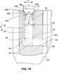
15 eine Schnittsansicht Nr. 1 ist, welche die aufnehmende Steckverbindung zeigt, die entlang einer Linie 15-15 in 14 geschnitten wurde, wenn das elastische Dichtungselement davon an dem Eingang des hohlen Abschnitts des Gehäuses davon gemäß der Ausführungsform der vorliegenden Erfindung angeordnet ist; 15 1 is a sectional view showing the female connector taken along line 15-15 in FIG 14 has been cut when the elastic sealing member thereof is disposed at the entrance of the hollow portion of the housing thereof according to the embodiment of the present invention;
16 eine Schnittsansicht Nr. 2 ist, welche die aufnehmende Steckverbindung zeigt, die entlang der Linie 15-15 in 14 geschnitten wurde, wenn das elastische Dichtungselement davon durch den hohlen Abschnitt des Gehäuses davon gemäß der Ausführungsform der vorliegenden Erfindung geführt wird; 16 FIG. 2 is a sectional view No. 2 showing the female connector taken along line 15-15 in FIG 14 was cut when the elastic sealing member thereof is guided by the hollow portion of the housing thereof according to the embodiment of the present invention;
17 eine Schnittsansicht Nr. 3 ist, welche die aufnehmende Steckverbindung zeigt, die entlang der Linie 15-15 in 14 geschnitten wurde, wenn das elastische Dichtungselement davon durch den hohlen Abschnitt des Gehäuses davon gemäß der Ausführungsform der vorliegenden Erfindung geführt wird; 17 3 is a sectional view showing the female connector taken along line 15-15 in FIG 14 was cut when the elastic sealing member thereof is guided by the hollow portion of the housing thereof according to the embodiment of the present invention;
18 eine Schnittsansicht Nr. 4 ist, welche die aufnehmende Steckverbindung zeigt, die entlang der Linie 15-15 in 14 geschnitten wurde, wenn das elastische Dichtungselement davon an der spezifischen Stelle des hohlen Abschnitts des Gehäuses davon gemäß der Ausführungsform der vorliegenden Erfindung platziert ist; 18 4 is a sectional view showing the female connector taken along line 15-15 in FIG 14 has been cut when the elastic sealing member thereof is placed at the specific location of the hollow portion of the housing thereof according to the embodiment of the present invention;
19 eine Draufsicht ist, welche eine herkömmliche wasserfeste Steckverbindung zeigt, die ein elastisches Dichtungselement gemäß der Patentreferenz besitzt; und 19 Fig. 11 is a plan view showing a conventional waterproof connector having an elastic sealing member according to the patent reference; and
20 eine Schnittsansicht ist, welche die herkömmliche wasserfeste Steckverbindung zeigt, wenn das elastische Dichtungselement gemäß der Patentreferenz an einem Gehäuse der herkömmlichen wasserfesten Steckverbindung befestigt ist. 20 is a sectional view showing the conventional waterproof connector, when the elastic sealing element according to the patent reference is attached to a housing of the conventional waterproof connector.
Hiernach werden bevorzugte Ausführungsformen der vorliegenden Erfindung mit Bezugnahme auf die beigefügten Zeichnungen beschrieben.Hereinafter, preferred embodiments of the present invention will be described with reference to the accompanying drawings.
1 ist eine perspektivische Ansicht, welche eine wasserdichte Steckverbindungsvorrichtung 1 zeigt, die von einer dazu oberen Fläche aus betrachtet wird, bevor eine aufnehmende Steckverbindung (eine wasserdichte Steckverbindung) 20 davon mit einem Steckerverbinder (einer zusammengehörenden Steckverbindung) 70 davon gemäß einer Ausführungsform der vorliegenden Erfindung verbunden wird. 2 ist eine perspektivische Ansicht, welche die wasserdichte Steckverbindungsvorrichtung 1 zeigt, nachdem eine aufnehmende Steckverbindung 20 davon mit einem Steckerverbinder 70 davon gemäß einer Ausführungsform der vorliegenden Erfindung verbunden wurde. 1 is a perspective view showing a waterproof connector device 1 which is viewed from an upper surface thereof before a female connector (a waterproof connector) 20 of which with a plug connector (a mating connector) 70 thereof according to an embodiment of the present invention is connected. 2 is a perspective view showing the waterproof connector device 1 shows after a female connector 20 of which with a plug connector 70 thereof has been joined in accordance with an embodiment of the present invention.
Wie in 1 und 2 gezeigt ist, wird die wasserdichte Steckverbindungsvorrichtung von einem Paar aus aufnehmender Steckverbindung 20 und Steckerverbinder 70 gebildet, welches in der Lage ist, entlang einer spezifischen Richtung (Pfeilrichtung α) miteinander verbunden zu werden. Es sollte angemerkt werden, dass sowohl die aufnehmende Steckverbindung 20 als auch der Steckerverbinder 70 in einer Richtung von links nach rechts in einer symmetrischen Form ausgebildet sind und in einer nicht symmetrischen Form ausgebildet sein können.As in 1 and 2 is shown, the waterproof connector device of a pair of female connector 20 and plug connectors 70 formed, which is able to be connected together along a specific direction (arrow direction α). It should be noted that both the female connector 20 as well as the plug connector 70 are formed in a direction from left to right in a symmetrical shape and may be formed in a non-symmetrical shape.
Bei einer Ausführungsform weist die aufnehmende Steckverbindung 20 einen hohlen Abschnitt 27 zur Aufnahme eines Teils des Steckerverbinders 70 auf. Ein Verriegelungsloch 31 ist an einer oberen Fläche der aufnehmenden Steckverbindung 20 ausgebildet. Ferner ist ein elastisches, eingreifendes Teil 82 an einer oberen Fläche des Steckerverbinders 70 ausgebildet, und ein vorstehender Verriegelungsabschnitt 81 ist an dem elastischen, eingreifenden Teil 82 ausgebildet. Wenn ein Teil des Steckerverbinders 70 in den hohlen Abschnitt 27 eingesetzt wird, kann der Steckerverbinder 70 auf die aufnehmende Steckverbindung 20 aufgesteckt werden. Wenn der Steckerverbinder 70 auf die aufnehmende Steckverbindung 20 aufgesteckt ist, wird der vorstehende Verriegelungsabschnitt 81 in das Verriegelungsloch 31 eingepasst und von innen nach außen hindurch gesteckt, so dass die aufnehmende Steckverbindung 20 fest mit dem Steckverbinder 70 verbunden ist. Ferner ist ein Einsatzabschnitt 83 in der Nähe des vorstehenden Verriegelungsabschnitts 81 angeordnet. Wenn der Einsatzabschnitt 83 nach unten in Richtung des Steckerverbinders 70 gedrückt wird, ist es dementsprechend möglich, den vorstehenden Verriegelungsabschnitt 81 mit dem Verriegelungsloch 31 außer Eingriff zu bringen.In one embodiment, the female connector 20 a hollow section 27 for receiving a part of the plug connector 70 on. A locking hole 31 is on an upper surface of the female connector 20 educated. Furthermore, an elastic, engaging part 82 on an upper surface of the male connector 70 formed, and a protruding locking portion 81 is on the elastic, engaging part 82 educated. If a part of the plug connector 70 in the hollow section 27 is used, the plug connector 70 on the receiving connector 20 be plugged. When the plug connector 70 on the receiving connector 20 is plugged, the above locking section 81 in the locking hole 31 fitted and inserted from inside to outside, so that the female connector 20 firmly with the connector 70 connected is. Further, an insert section 83 near the protruding locking portion 81 arranged. When the insert section 83 down in the direction of the plug connector 70 is pressed, it is accordingly possible, the protruding locking portion 81 with the locking hole 31 to disengage.
Bei der Ausführungsform wird, wenn die wasserdichte Steckverbindungsvorrichtung 1 verwendet wird, eine Vielzahl von Kabeln (nicht gezeigt) mit sowohl der aufnehmenden Steckverbindung 20 als auch dem Steckerverbinder 70 verbunden. Insbesondere weist die aufnehmende Steckverbindung 20 einen Entnahmeausgang 47 an einer Seite auf, welche der Seite, an der er mit dem Steckerverbinder 70 verbunden ist, gegenüber liegt, und der Steckverbinder 77 weist einen Entnahmeausgang 77 an einer Seite auf, welche der Seite, an der er mit der aufnehmenden Steckverbindung 20 verbunden ist, gegenüber liegt. Wenn eine Vielzahl von Kabeln mit der aufnehmenden Steckverbindung 20 verbunden ist, werden die Kabel durch den Entnahmeausgang 47 herausgeführt. Ähnlich, wenn eine Vielzahl von Kabeln mit dem Steckerverbinder 70 verbunden ist, werden die Kabel durch den Entnahmeausgang 77 herausgeführt. Ferner umfassen sowohl die aufnehmende Steckverbindung 20 als auch der Steckerverbinder 70 eine Vielzahl von (nicht gezeigten) Kontakten, welche darin entsprechend zu den Kabeln angeordnet sind, so dass es möglich ist, die Kabel elektrisch durch die Kontakte miteinander zu verbinden.In the embodiment, when the waterproof connector device 1 is used, a plurality of cables (not shown) with both the female connector 20 as well as the plug connector 70 connected. In particular, the female connector has 20 a withdrawal exit 47 on one side, which is the side where it connects to the plug connector 70 is connected, opposite, and the connector 77 has an extraction exit 77 on one side on which the side where he is with the female connector 20 is connected, opposite. If a variety of cables with the female connector 20 The cables are connected through the extraction outlet 47 led out. Similarly, if a variety of cables to the plug connector 70 The cables are connected through the extraction outlet 77 led out. Further, both include the female connector 20 as well as the plug connector 70 a plurality of contacts (not shown) disposed therein corresponding to the cables, so that it is possible to electrically connect the cables to each other through the contacts.
Insbesondere weist der Steckerverbinder 70 ein Gehäuse 71 und eine Vielzahl von Kontakten auf, welche durch das Gehäuse gehalten werden. Das Gehäuse 71 ist in Form eines langgestreckten Elements mit einem im Wesentlichen rechteckigen Querschnitt ausgebildet. Ferner weist das Gehäuse 71 einen Einfügeabschnitt 71A auf, der eine geringe Abmessung aufweist, um in den hohlen Abschnitt 27 der aufnehmenden Steckverbindung 20 eingefügt zu werden, und einen Kabel-Entnahmeabschnitt 71B mit einer großen Abmessung. Der Einfügeabschnitt 71A ist mit dem elastischen, eingreifenden Teil 82 versehen, welches sich zum Kabel-Entnahmeabschnitt 71B hin erstreckt. Wenn die aufnehmende Steckverbindung 20 mit dem Steckerverbinder 70 verbunden ist, kommt das elastische, eingreifende Teil 82 mit der aufnehmenden Steckverbindung 20 in Eingriff. Ein vorstehender Verriegelungsabschnitt 81 ist an dem elastischen, eingreifenden Teil 82 des Einfügeabschnitts 71A angeordnet, und ein Einsatzabschnitt 83 ist benachbart zum vorstehenden Verriegelungsabschnitt 81 neben dem Kabel-Entnahmeabschnitt 71B zum Bedienen des elastischen, eingreifenden Teils 82 angeordnet.In particular, the male connector 70 a housing 71 and a plurality of contacts held by the housing. The housing 71 is formed in the form of an elongated member having a substantially rectangular cross-section. Furthermore, the housing has 71 an insertion section 71A on, which has a small dimension to enter the hollow section 27 the receiving connector 20 to be inserted, and a cable removal section 71B with a big dimension. The insertion section 71A is with the elastic, engaging part 82 provided, which is the cable removal section 71B extends. If the receiving connector 20 with the plug connector 70 connected, comes the elastic, engaging part 82 with the female connector 20 engaged. A protruding locking section 81 is on the elastic, engaging part 82 of the insertion section 71A arranged, and an insert section 83 is adjacent to the protruding locking portion 81 next to the cable removal section 71B for operating the elastic, engaging part 82 arranged.
Bei der Ausführungsform weist der Steckerverbinder 20 ein Gehäuse 21, eine Vielzahl von Kontakten, welche durch das Gehäuse 21 gehalten werden, und ein elastisches Dichtelement 50 auf. Ähnlich zum Gehäuse 71 des Steckerverbinders 70, ist das Gehäuse 21 in Form eines langgestreckten Elements mit einem im Wesentlichen rechteckigen Querschnitt ausgebildet. Ferner weist das Gehäuse 21 einen Basisabschnitt 21C mit einer kleinen Abmessung, welcher im Wesentlichen in dessen Mitte angeordnet ist, auf, wobei ein Aufnahmeabschnitt 21A mit einer großen Abmessung an einer Seite des Basisabschnitts 21C angeordnet ist und ein Kabel-Entnahmeabschnitt 21B mit einer hohlen Form an der anderen Seite des Basisabschnitts 21C angeordnet ist. Der Einfügeabschnitt 21A weist einen hohlen Abschnitt 27 zur Aufnahme des Einfügeabschnitts 71A des Steckerverbinders 70 und des elastischen Dichtungselements 50 und ein Verriegelungsloch 31 zum Eingriff mit dem Steckerverbinder 70 auf.In the embodiment, the male connector 20 a housing 21 , a variety of contacts, which through the housing 21 are held, and an elastic sealing element 50 on. Similar to the case 71 of the plug connector 70 , is the case 21 formed in the form of an elongate member having a substantially rectangular cross-section. Furthermore, the housing has 21 a base section 21C with a small dimension, which is arranged substantially in the center thereof, wherein a receiving portion 21A with a large dimension on one side of the base section 21C is arranged and a cable removal section 21B with a hollow shape on the other side of the base section 21C is arranged. The insertion section 21A has a hollow section 27 for receiving the insertion section 71A of the plug connector 70 and the elastic sealing element 50 and a locking hole 31 for engagement with the plug connector 70 on.
Bei der Ausführungsform wird, ähnlich wie beim Steckerverbinder 70, das elastische Dichtungselement 50 entlang des in dem Aufnahmeabschnitt 21A gebildeten hohlen Abschnitts 27 in der Richtung α geführt, welche dieselbe ist, wie die Montagerichtung zwischen der aufnehmenden Steckverbindung 20 und dem Steckerverbinder 70. Nachdem das elastische Dichtungselement 50 entlang dem hohlen Abschnitt 27 geführt wurde, wird das elastische Dichtungselement 50 an einer spezifischen Stelle im Gehäuse 21 angeordnet. Das Gehäuse 21 weist ausgesparte Abschnitte 28 und 29 auf, welche sich in einer senkrechten Richtung und einer seitlichen Richtung erstrecken und in dem hohlen Abschnitt 27 an Stellen ausgebildet sind, welche den sich erstreckenden Abschnitten oder in Eingriff stehenden Abschnitten 51A und 51B des elastischen Dichtungselements 50 entsprechen.In the embodiment, similar to the male connector 70 , the elastic sealing element 50 along the in the receiving section 21A formed hollow section 27 guided in the direction α, which is the same as the mounting direction between the female connector 20 and the male connector 70 , After the elastic sealing element 50 along the hollow section 27 was guided, the elastic sealing element 50 at a specific location in the housing 21 arranged. The housing 21 has recessed sections 28 and 29 which extend in a vertical direction and a lateral direction and in the hollow portion 27 are formed at locations which the extending portions or engaged portions 51A and 51B the elastic sealing element 50 correspond.
Eine Konfiguration des in der aufnehmenden Steckverbindung 20 angeordneten elastischen Dichtungselements 50 wird im Folgenden unter Bezugnahme auf 3 bis 7 erklärt werden. 3 ist eine Vorderansicht, welche das elastische Dichtungselement der aufnehmenden Steckverbindung 20 oder der wasserdichten Steckverbindung der wasserdichten Steckverbindungsvorrichtung 1 gemäß einer Ausführungsform der vorliegenden Erfindung zeigt. 4 ist eine perspektivische Ansicht, welche das elastische Dichtungselement 50 der wasserdichten Steckverbindung 20 zeigt, das von einer dazu oberen Fläche aus gemäß einer Ausführungsform der vorliegenden Erfindung betrachtet wird. 5 ist eine perspektivische Ansicht, welche das elastische Dichtungselement 50 der wasserdichten Steckverbindung 20 zeigt, das von einer dazu unteren Fläche gemäß einer Ausführungsform der vorliegenden Erfindung betrachtet wird. 6 ist eine Draufsicht, welche das elastische Dichtungselement 50 der wasserdichten Steckverbindung 20 gemäß einer Ausführungsform der vorliegenden Erfindung zeigt. 7 ist eine Schnittansicht, welche das elastische Dichtungselement 50 der wasserdichten Steckverbindung 20 zeigt, das entlang einer Linie 7-7 in 6 gemäß einer Ausführungsform der vorliegenden Erfindung geschnitten wurde.A configuration of the in the female connector 20 arranged elastic sealing element 50 is below with reference to 3 to 7 be explained. 3 is a front view showing the elastic sealing element of the female connector 20 or the waterproof connector of the waterproof connector device 1 according to an embodiment of the present invention. 4 is a perspective view showing the elastic sealing element 50 the watertight plug connection 20 which is viewed from an upper surface thereof according to an embodiment of the present invention. 5 is a perspective view showing the elastic sealing element 50 the watertight plug connection 20 which is viewed from a lower surface thereof according to an embodiment of the present invention. 6 is a plan view showing the elastic sealing element 50 the watertight plug connection 20 according to an embodiment of the present invention. 7 is a sectional view showing the elastic sealing element 50 the watertight plug connection 20 shows that along a line 7-7 in 6 was cut according to an embodiment of the present invention.
Wie in den 3 bis 7 gezeigt wird, ist das elastische Dichtungselement 50 integral aus einem Material wie beispielsweise einem Gummi oder einem Kunststoff ausgebildet. Ferner umfasst das elastische Dichtungselement 50 einen Hauptkörperabschnitt 52, welcher zur Verleihung einer wasserdichten Funktion innerhalb des hohlen Abschnitts 27 anzuordnen ist, und die in Eingriff stehenden Abschnitte 51 (51A und 51B), welche außerhalb des hohlen Abschnitts 27 zum Eingriff des elastischen Dichtungselements 50 mit dem Gehäuse 21 anzuordnen sind.As in the 3 to 7 is shown is the elastic sealing element 50 integrally formed of a material such as a rubber or a plastic. Furthermore, the elastic sealing element comprises 50 a main body section 52 which is used to provide a watertight function within the hollow section 27 is to be arranged, and the engaged sections 51 ( 51A and 51B ) which outside the hollow section 27 for engagement of the elastic sealing element 50 with the housing 21 are to be arranged.
Bei der Ausführungsform ist der Hauptkörperabschnitt 52 in einer ringförmigen Form mit einer im Wesentlichen rechteckigen Gestalt in einer Draufsicht ausgebildet (ein kurzes zylindrisches Element mit einer im Wesentlichen rechteckigen Querschnittsform) und besitzt eine spezifische Breite in einer Führungsrichtung (einer Pfeilrichtung α). Der Hauptkörperabschnitt 52 umfasst eine Ausstülpung 53 der äußeren Fläche, welche eine ringförmige Form an dessen äußerer Umfangsfläche an einer Mitte in der Richtung der Breite besitzt. Wenn der Hauptkörperabschnitt 52 in dem hohlen Abschnitt 27 aufgenommen ist, wird die Ausstülpung der äußeren Fläche gegen eine innere Umfangsfläche des Gehäuses 21 gedrückt. Es ist dementsprechend möglich, die wasserdichte Funktion zwischen der inneren Umfangsfläche des Gehäuses 21 und der äußeren Fläche des elastischen Dichtungselements 50 zu verleihen.In the embodiment, the main body portion 52 formed in an annular shape having a substantially rectangular shape in a plan view (a short cylindrical member having a substantially rectangular cross-sectional shape) and has a specific width in a guide direction (an arrow direction α). The main body section 52 includes a protuberance 53 the outer surface having an annular shape on the outer peripheral surface thereof at a center in the width direction. When the main body section 52 in the hollow section 27 is received, the protuberance of the outer surface against an inner peripheral surface of the housing 21 pressed. It is accordingly possible to have the waterproof function between the inner peripheral surface of the housing 21 and the outer surface of the elastic sealing member 50 to rent.
Bei der Ausführungsform umfasst der Hauptkörperabschnitt 52 ferner eine Ausstülpung 57 der inneren Fläche, welche eine ringförmige Form an dessen innerer Umfangsfläche an einer zu jener der Ausstülpung 53 der äußeren Fläche in der Führungsrichtung α verschobenen Stelle besitzt. Wenn der Einfügeabschnitt 71A des Steckerverbinders 70 in den hohlen Abschnitt 27 der aufnehmenden Steckverbindung 20 eingesetzt ist, wird die Ausstülpung 57 der inneren Fläche an eine äußere Umfangsfläche des Einfügeabschnitts 71A an dessen entfernte Endseite gepresst und berührt diese fest. Es ist dementsprechend möglich, die wasserdichte Funktion zwischen der äußeren Umfangsfläche des Steckerverbinders 70 und der inneren Fläche des elastischen Dichtungselements 50 zu verleihen (dies wird später in Bezug auf 10 beschrieben).In the embodiment, the main body portion comprises 52 also a protuberance 57 the inner surface having an annular shape on the inner peripheral surface at one to that of the protuberance 53 the outer surface in the guide direction α has shifted position. If the insert section 71A of the plug connector 70 in the hollow section 27 the receiving connector 20 is inserted, the protuberance becomes 57 the inner surface to an outer peripheral surface of the insertion portion 71A pressed on the remote end side and touches them firmly. Accordingly, it is possible to have the waterproof function between the outer peripheral surface of the male connector 70 and the inner surface of the elastic sealing member 50 to lend (this will be later with respect to 10 described).
Bei der Ausführungsform umfasst der Hauptkörperabschnitt 52 weiter einen Stufenabschnitt 66 an dessen entfernter Endseite in der Führungsrichtung α und einen Montageabschnitt 65 mit einer schmalen Spitze, welche zum Stufenabschnitt 66 benachbart angeordnet ist. Wenn der Hauptkörperabschnitt 52 eine äußere Kraft in der Führungsrichtung α erfährt, wird der Montageabschnitt leicht verformt, so dass das elastische Dichtungselement 50 in der Lage ist, sich leicht in der Führungsrichtung α zu bewegen.In the embodiment, the main body portion comprises 52 continue a step section 66 at its distal end side in the guide direction α and a mounting portion 65 with a narrow tip leading to the step section 66 is arranged adjacent. When the main body section 52 an external force in the guide direction α undergoes, the mounting portion is slightly deformed, so that the elastic sealing member 50 is able to easily move in the guide direction α.
Bei der Ausführungsform umfasst der Hauptkörperabschnitt 52 weiter einen oberen Umfangsrand 63, welcher in einer Draufsicht eine im Wesentlichen rechteckige Form besitzt. Drei der in Eingriff stehenden Abschnitte 51A und 51B sind an dem oberen Umfangsrand 63 angeordnet, insbesondere an drei Seiten der im Wesentlichen rechteckigen Form, und erstrecken sich schräg von den Mitten der drei Seiten zu einer oberen Seite hin. Wenn die in Eingriff stehenden Abschnitte 51A und 51B an den drei Seiten der im Wesentlichen rechteckigen Form angeordnet sind, im Gegensatz zu einer Konfiguration, bei welcher die in Eingriff stehenden Abschnitte 51A und 51B an nur einer Seite oder zwei Seiten der im Wesentlichen rechteckigen Form gebildet wird, ist es möglich, das elastische Dichtungselement 50 an dem Gehäuse 21 in einem stabileren Zustand zu befestigen. Ferner, im Gegensatz zu einer Konfiguration, bei welcher die in Eingriff stehenden Abschnitte 51A und 51B an vier Seiten der im Wesentlichen rechteckigen Form angeordnet sind, ist es möglich, zu verhindern, dass die Größe der wasserdichten Steckverbindungsvorrichtung 1 übermäßig groß wird.In the embodiment, the main body portion comprises 52 further an upper peripheral edge 63 which has a substantially rectangular shape in a plan view. Three of the engaged sections 51A and 51B are at the upper peripheral edge 63 arranged, in particular on three sides of the substantially rectangular shape, and extend obliquely from the centers of the three sides to an upper side. When the engaged sections 51A and 51B are arranged on the three sides of the substantially rectangular shape, in contrast to a configuration in which the engaging portions 51A and 51B at only one side or two sides of the substantially rectangular shape, it is possible to use the elastic sealing member 50 on the housing 21 to fix in a more stable condition. Further, in contrast to a configuration in which the engaged portions 51A and 51B are arranged on four sides of the substantially rectangular shape, it is possible to prevent the size of the waterproof connector device 1 becomes overly large.
Bei der Ausführung erstrecken sich alle in Eingriff stehenden Abschnitte 51A und 51B in einer Richtung, die von einem radialen Zentrum des Hauptkörperabschnitts 52 (eine Pfeilrichtung β) weggerichtet ist. Unter den drei in Eingriff stehenden Abschnitten 51A und 51B besitzen zwei der in Eingriff stehenden Abschnitte 51A, die sich gegenüber stehend angeordnet sind, eine identische Form und eine identische Größe. Der in Eingriff stehende Abschnitt 51B, welcher zwischen den in Eingriff stehenden Abschnitten 51A angeordnet ist, besitzt eine etwas kürzere Länge als die in Eingriff stehenden Abschnitte 51A. Andere Konfigurationen des in Eingriff stehenden Abschnitts 51B sind ähnlich wie die der in Eingriff stehenden Abschnitte 51A. In der folgenden Beschreibung werden die Buchstaben ”A” und ”B” an die Bezugszeichen, welche den in Eingriff stehenden Abschnitten 51A und 51B und Komponenten der in Eingriff stehenden Abschnitte 51A und 51B zugeordnet sind, nur angefügt, wenn die in Eingriff stehenden Abschnitte 51A und 51B unterschieden werden müssen.In the embodiment, all engaging portions extend 51A and 51B in a direction from a radial center of the main body portion 52 (an arrow direction β) is directed away. Under the three engaging sections 51A and 51B have two of the engaged sections 51A , which are arranged opposite standing, an identical shape and an identical size. The engaged section 51B which is between the engaged sections 51A is arranged, has a slightly shorter length than the engaged portions 51A , Other configurations of the engaged portion 51B are similar to the engaged sections 51A , In the following description, the letters "A" and "B" will be referred to the reference numerals representing the engaged portions 51A and 51B and components of the engaged portions 51A and 51B are assigned only attached when the engaged sections 51A and 51B have to be differentiated.
Bei der Ausführungsform umfasst der in Eingriff stehende Abschnitt 51 einen Kopfabschnitt 54, welcher an einem sich daran erstreckenden Endabschnitt gebildet ist, und einen Halsabschnitt 55, welcher den Kopfabschnitt 53 mit dem Hauptkörperabschnitt 52 verbindet. Der Kopfabschnitt 54 ist zum Beispiel bei dessen Draufsicht in einer umgekehrten Trapezform ausgebildet. Der Kopfabschnitt 54 umfasst weiter ein Paar Bergabschnitte 58 an einem verjüngten entfernten Endabschnitt davon, welcher in der Führungsrichtung α vorsteht, und die Bergabschnitte 58 sind durch einen ausgesparten Abschnitt 56, welcher eine umgekehrte U-förmige Form besitzt, abgetrennt. Es sollte angemerkt werden, dass der entfernte Endabschnitt, welcher von den Bergabschnitten 58 und dem ausgesparten Abschnitt 56 gebildet wird, dazu ausgelegt ist, um als ein Verformungsabschnitt zu fungieren.In the embodiment, the engaged portion comprises 51 a head section 54 formed on an end portion extending thereon and a neck portion 55 which is the head section 53 with the main body section 52 combines. The head section 54 is formed, for example, in its plan view in an inverted trapezoidal shape. The head section 54 further includes a pair of mountain sections 58 at a tapered distal end portion thereof projecting in the guide direction α, and the mountain portions 58 are through a recessed section 56 , which has an inverted U-shaped form, separated. It should be noted that the distal end portion of which of the mountain portions 58 and the recessed section 56 is formed to function as a deformation portion.
Bei der Ausführungsform, wenn die Bergabschnitte 58 gegen eine untere Fläche 34b eines ausgeschnittenen Abschnitts 34 des Gehäuses 21 (in Bezug auf 1 und 2) in der Nähe eines Einbauabschnitts 33 (in Bezug auf 1 und 2), wo der Kopfabschnitt 54 in der Führungsrichtung α aufgenommen wird, anstoßen, wird der entfernte Endabschnitt des Kopfabschnitts 54 durch den ausgesparten Abschnitt 56 und die Bergabschnitte 58 derartig verformt, dass die Bergabschnitte 58 zusammenfallen. Da der entfernte Endabschnitt des Kopfabschnitts 54 verformt wird, sogar nachdem der in Eingriff stehende Abschnitt 51 gegen die untere Fläche 34b des ausgeschnittenen Abschnitts 34 angestoßen hat, ist der in Eingriff stehende Abschnitt 51 in der Lage, sich weiter in die Führungsrichtung α zu bewegen.In the embodiment, when the mountain sections 58 against a lower surface 34b a cut-out section 34 of the housing 21 (in relation to 1 and 2 ) near an installation section 33 (in relation to 1 and 2 ), where the head section 54 in the guide direction α, abut, becomes the distal end portion of the head portion 54 through the recessed section 56 and the mountain ranges 58 deformed so that the mountain sections 58 coincide. Because the distal end portion of the head section 54 is deformed even after the engaging portion 51 against the lower surface 34b the cut-out section 34 is the engaged section 51 able to move further in the guide direction α.
Bei der Ausführungsform umfasst der Kopfabschnitt 54 weiter eine obere Fläche 60, welche eine flache Form besitzt und an einem hinteren Endabschnitt davon gegenüber dem entfernten Endabschnitt (das heißt ein anstoßender Endabschnitt) in der Führungsrichtung α ausgebildet ist. Ferner weist der Kopfabschnitt 54 weiter Ohrenabschnitte 59 auf, welche weiter als die Bergabschnitte 58 nach außen (eine Pfeilrichtung γ oder eine vorstehende Richtung γ) vorstehen. Dementsprechend sind verjüngende Abschnitte 69 vom entfernten Endabschnitt des Kopfabschnitts 54 zur gegenüber liegenden Seite vom entfernten Endabschnitt in der Führungsrichtung α ausgebildet. Es sollte angemerkt werden, dass der Kopfabschnitt 54 ohne den Ohrenabschnitt 59 eine Breite ”a” in der vorstehenden Richtung γ aufweist, welche gleich einer Breite ”a” des Halsabschnitts 55 in der vorstehenden Richtung γ ist (in Bezug auf 6).In the embodiment, the head portion comprises 54 continue an upper surface 60 which has a flat shape and is formed at a rear end portion thereof opposite to the distal end portion (that is, an abutting end portion) in the guide direction α. Furthermore, the head section 54 further ear sections 59 on which further than the mountain sections 58 outwardly (an arrow direction γ or a protruding direction γ) protrude. Accordingly, tapered sections 69 from the distal end portion of the head section 54 formed to the opposite side from the distal end portion in the guide direction α. It should be noted that the head section 54 without the ear section 59 has a width "a" in the protruding direction γ, which is equal to a width "a" of the neck portion 55 in the above direction γ is (with respect to 6 ).
Eine innere Struktur des Gehäuses 21 der aufnehmenden Steckverbindung 20 an deren Aufnahmeabschnitt 21A und eine Vorgehensweise des Einsetzens des elastischen Dichtungselements 50 und des Steckerverbinders 70 in den Aufnahmeabschnitt 21A wird im Folgenden unter Bezugnahme auf die 8 bis 10 erklärt.An internal structure of the housing 21 the receiving connector 20 at the receiving section 21A and a procedure of inserting the elastic sealing member 50 and the plug connector 70 in the recording section 21A is explained below with reference to the 8th to 10 explained.
8 ist eine Schnittsansicht Nr. 1, welche die innere Struktur des Gehäuses 21 der aufnehemenden Steckverbindung 20 zeigt, wenn das elastische Dichtungselement 50 davon an einem Eingang des hohlen Abschnitts 27 des Gehäuses 21 gemäß der Ausführungsform der vorliegenden Erfindung angeordnet ist. 9 ist eine Querschnittsansicht Nr. 2, welche die innere Struktur des Gehäuses 21 der aufnehmenden Steckverbindung 20 zeigt, wenn das elastische Dichtungselement 50 davon an einer spezifischen Stelle des hohlen Abschnitts 27 des Gehäuses 21 platziert ist, nachdem das elastische Dichtungselement 50 entlang des hohlen Abschnitts 27 in der Führungsrichtung gemäß der Ausführungsform der vorliegenden Erfindung geführt wurde. 10 ist eine Schnittsansicht Nr. 3, welche die innere Struktur des Gehäuses 21 der aufnehmenden Steckverbindung 20 zeigt, wenn der Einfügeabschnitt 71A des Steckerverbinders 70 in den hohlen Abschnitt 27 des Gehäuses 21 eingefügt ist, nachdem das elastische Dichtungselement 50 an der spezifischen Stelle gemäß der Ausführungsform der vorliegenden Erfindung platziert wurde. 8th is a sectional view no. 1 showing the internal structure of the housing 21 the receiving plug-in connection 20 shows when the elastic sealing element 50 of it at an entrance of the hollow section 27 of the housing 21 is arranged according to the embodiment of the present invention. 9 Figure 2 is a cross-sectional view showing the internal structure of the housing 21 the receiving connector 20 shows when the elastic sealing element 50 of which at a specific point of the hollow section 27 of the housing 21 is placed after the elastic sealing element 50 along the hollow section 27 was guided in the guide direction according to the embodiment of the present invention. 10 is a sectional view no. 3 showing the internal structure of the housing 21 the receiving connector 20 shows when the insertion section 71A of the plug connector 70 in the hollow section 27 of the housing 21 is inserted after the elastic sealing element 50 at the specific location according to the embodiment of the present invention.
Bei der Ausführungsform wird, in dem Zustand, wenn der Hauptkörperabschnitt 52, insbesondere die Ausstülpung der äußeren Fläche 53, des elastischen Dichtungselements 50 fest gegen die innere Fläche des hohlen Abschnitts 27 gedrückt wird, das elastische Dichtungselement 50 entlang der Führungsrichtung α geführt. Während das elastische Dichtungselement 50 geführt wird, verbleiben die Kopfabschnitte 54 innerhalb des Gehäuses 21. Wenn das elastische Dichtungselement 50 vollständig an der spezifischen Stelle (den Einbauabschnitten 33) platziert ist, werden die Kopfabschnitte 54 nach außen ausgestellt.In the embodiment, in the state when the main body portion 52 , in particular the protuberance of the outer surface 53 , the elastic sealing element 50 firmly against the inner surface of the hollow section 27 is pressed, the elastic sealing element 50 guided along the guide direction α. While the elastic sealing element 50 is guided, the head sections remain 54 inside the case 21 , When the elastic sealing element 50 completely at the specific place (installation sections 33 ) are placed, the head sections 54 issued to the outside.
Bei der Ausführungsform sind Führungsnuten 23 im hohlen Abschnitt 27 entlang der Führungsrichtung α zum Führen der in Eingriff stehenden Abschnitte 51A des elastischen Dichtungselements 50 ausgebildet. Die Führungsnuten 23 können zum Beispiel von Führungsrippen gebildet sein. In einem Zustand, in welchem die Führungsnuten 23 die Halsabschnitte 55A, welche die Kopfabschnitte 54A mit den Hauptkörperabschnitten 52A verbinden, zwischen sich legen, wird dementsprechend das elastische Dichtungselement 50 an den Stellen geführt, welche an symmetrischen Positionen in der von links nach rechts verlaufenden Richtung angeordnet sind.In the embodiment, guide grooves 23 in the hollow section 27 along the guide direction α for guiding the engaging portions 51A the elastic sealing element 50 educated. The guide grooves 23 For example, they may be formed by guide ribs. In a state in which the guide grooves 23 the neck sections 55A which the head sections 54A with the main body sections 52A connect, put between them, accordingly, the elastic sealing element 50 at the points which are arranged at symmetrical positions in the left-to-right direction.
Bei der oben beschriebenen Konfiguration ist es möglich, die in Eingriff stehenden Abschnitte 51A leicht zu den spezifischen Stellen im Gehäuse 21 zu führen. Es ist weiter möglich, das elastische Dichtungselement 50 sicher an den spezifischen Stellen zu befestigen. Es sollte angemerkt werden, dass der hohle Abschnitt 27 nicht mit einer Führungsnut zum Führen des in Eingriff stehenden Abschnitts 51B versehen ist. Da die in Eingriff stehenden Abschnitte 51A in einer stabilen Weise geführt sind, ist es jedoch möglich, demzufolge den in Eingriff stehenden Abschnitt 51B stabil zu führen. Alternativ kann der hohle Abschnitt 27 ohne eine Führungsnut zum Führen des in Eingriff stehenden Abschnitts 51B versehen sein.In the configuration described above, it is possible to have the engaged portions 51A easy to the specific locations in the housing 21 respectively. It is further possible, the elastic sealing element 50 secure to the specific locations. It should be noted that the hollow section 27 not with a guide groove for guiding the engaged portion 51B is provided. Because the engaged sections 51A are guided in a stable manner, however, it is possible, consequently, the engaged portion 51B stable to lead. Alternatively, the hollow section 27 without a guide groove for guiding the engaged portion 51B be provided.
Wie in 8 gezeigt ist, umfasst die aufnehmende Steckverbindung 20 einen regulierenden Stufenabschnitt 38, und eine Nut 35 ist um den regulierenden Stufenabschnitt 38 herum ausgebildet. Der regulierende Stufenabschnitt 38 weist weiter eine anstoßende Fläche 43 auf. Wie in den 9 und 10 gezeigt ist, wenn das elastische Dichtungselement 50 entlang des hohlen Abschnitts 27 in der Führungsrichtung α geführt wird und das elastische Dichtungselement 50 an der spezifischen Stelle im Gehäuse 21 platziert ist, wird der am Hauptkörperabschnitt 52 des elastischen Dichtungselements 50 angeordnete Montageabschnitt 65 in die Nut 35 eingesetzt, welche um den regulierenden Stufenabschnitt 38 des Gehäuses 21 herum ausgebildet ist. Es ist dementsprechend möglich, den Hauptkörperabschnitt 52 sicher an der spezifischen Stelle im Gehäuse 21 zu positionieren.As in 8th shown includes the female connector 20 a regulating step section 38 , and a groove 35 is around the regulating step section 38 trained around. The regulating step section 38 has an adjoining surface 43 on. As in the 9 and 10 is shown when the elastic sealing element 50 along the hollow section 27 is guided in the guide direction α and the elastic sealing element 50 at the specific location in the housing 21 is placed, the at the main body portion 52 the elastic sealing element 50 arranged mounting section 65 in the groove 35 used, which around the regulating step section 38 of the housing 21 is formed around. It is accordingly possible to use the main body portion 52 safely at the specific location in the housing 21 to position.
Wie in 10 gezeigt ist, stößt eine vordere Fläche des Einfügeabschnitts 71A gegen die anstoßende Fläche 43 des regulierenden Stufenabschnitts 39 an, so dass der Steckerverbinder 70 eingeschränkt ist, sich weiter zu bewegen, wenn der Einfügeabschnitt 71A des Steckerverbinders 70 in den hohlen Abschnitt 27 des Gehäuses 21 eingefügt ist. Zu diesem Zeitpunkt steht die Ausstülpung 57 der inneren Fläche des Hauptkörperabschnitts 52 in festem Kontakt mit der äußeren Umfangsfläche des Einfügeabschnitts 71A des Steckerverbinders 70. Es ist dementsprechend möglich, Wasserdichtigkeit zwischen dem elastischen Dichtelement 50 und dem Steckerverbinder 70 zu erzielen. Gleichzeitig werden die (nicht gezeigten) Kontakte der aufnehmenden Steckverbindung 20 mit den (nicht gezeigten) Kontakten des Steckerverbinders 70 in der Nähe der anstoßenden Fläche 43 des regulierenden Stufenabschnitts 38 in Verbindung gebracht. Ferner umfasst das Gehäuse 21 der aufnehmenden Steckverbindung 20 Lanzen 42, welche in in der anstoßenden Fläche 43 des regulierenden Stufenabschnitts 39 ausgebildeten Löchern 37 aufgenommen sind (in Bezug auf 11), so dass die (nicht gezeigten) Kontakte der aufnehmenden Steckverbindung 20 im Kontaktzustand mit den (nicht gezeigten Kontakten des Steckerverbinders 70 sicher gehalten werden.As in 10 is shown, abuts a front surface of the insertion portion 71A against the adjoining surface 43 of the regulating step section 39 on, leaving the plug connector 70 is restricted to move further when the insertion section 71A of the plug connector 70 in the hollow section 27 of the housing 21 is inserted. At this time stands the protuberance 57 the inner surface of the main body portion 52 in firm contact with the outer peripheral surface of the inserting portion 71A of the plug connector 70 , It is accordingly possible waterproofness between the elastic sealing element 50 and the male connector 70 to achieve. At the same time, the contacts (not shown) of the female connector become 20 with the contacts (not shown) of the plug connector 70 near the adjoining area 43 of the regulating step section 38 connected. Furthermore, the housing comprises 21 the receiving connector 20 lances 42 which in in the adjoining area 43 of the regulating step section 39 trained holes 37 are included (in relation to 11 ) so that the contacts (not shown) of the female connector 20 in the contact state with the contacts (not shown) of the plug connector 70 be kept safe.
Mit Bezug auf die 11 bis 13 wird eine Bewegung der Kopfabschnitte 55 des elastischen Dichtungselements 50 im Folgenden erklärt, wenn das elastische Dichtungselement 50 entlang des hohlen Abschnitts 27 des Gehäuses 21 geführt wird.With reference to the 11 to 13 becomes a movement of the head sections 55 the elastic sealing element 50 explained below when the elastic sealing element 50 along the hollow section 27 of the housing 21 to be led.
11 ist eine Draufsicht Nr. 1, welche die aufnehmende Steckverbindung 20 zeigt, die in der Führungsrichtung α gemäß einer Ausführungsform der vorliegenden Erfindung betrachtet wird. 12 ist eine Schnittsansicht Nr. 1, welche die aufnehmende Steckverbindung 20 zeigt, die entlang einer Linie 12-12 in 11 geschnitten wurde, wenn das elastische Dichtungselement 50 davon an dem Eingang des hohlen Abschnitts 27 des Gehäuses 21 davon gemäß der Ausführungsform der vorliegenden Erfindung angeordnet ist. 13 ist eine Schnittsansicht Nr. 2, welche die aufnehmende Steckverbindung 20 zeigt, die entlang einer Linie 12-12 in 11 geschnitten wurde, wenn das elastische Dichtungselement 50 davon an einer spezifischen Stelle in dem Gehäuse 21 angeordnet ist, nachdem das elastische Dichtungselement 50 durch den hohlen Abschnitt 27 des Gehäuses 21 davon gemäß der Ausführungsform der vorliegenden Erfindung geführt wurde; Es sollte angemerkt werden, dass das in 11 gezeigte elastische Dichtungselement 50 an der in 13 gezeigten spezifischen Stelle platziert ist, das heißt, dass das elastische Dichtungselement 50 vollständig an dem hohlen Abschnitt 27 der aufnehmenden Steckverbindung 20 befestigt ist. 11 is a plan view no. 1, which is the female connector 20 which is considered in the guide direction α according to an embodiment of the present invention. 12 is a sectional view no. 1, which shows the female connector 20 shows that along a line 12-12 in 11 was cut when the elastic sealing element 50 of which at the entrance of the hollow section 27 of the housing 21 thereof is arranged according to the embodiment of the present invention. 13 is a sectional view no. 2, which the female connector 20 shows that along a line 12-12 in 11 was cut when the elastic sealing element 50 of which at a specific location in the housing 21 is arranged after the elastic sealing element 50 through the hollow section 27 of the housing 21 thereof was guided according to the embodiment of the present invention; It should be noted that in 11 shown elastic sealing element 50 at the in 13 placed specific location, that is, the elastic sealing element 50 completely on the hollow section 27 the receiving connector 20 is attached.
Wie oben beschrieben wurde, legen bei der Ausführungsform die Führungsnuten 23 die Kopfabschnitte 55A des in Eingriff stehenden Abschnitts 51A wie ein Sandwich zwischen sich. Wie in 12 gezeigt ist, ist eine Breite der Führungsnut 23 in der vorstehenden Richtung γ ausgebildet, um entlang der Führungsrichtung α abzunehmen. Wenn das elastische Dichtungselement 50 entlang der Führungsnut geführt wird, spannt bei dieser Konfiguration die Führungsnut 23 schrittweise den Kopfabschnitt 55A des in Eingriff stehenden Abschnitts 51A des elastischen Dichtungselements 50 ein. Es ist dementsprechend möglich, das elastische Dichtungselement 50 leicht und sicher zu befestigen.As described above, in the embodiment, the guide grooves 23 the head sections 55A of the engaged portion 51A like a sandwich between them. As in 12 is shown, is a width of the guide groove 23 formed in the protruding direction γ to decrease along the guide direction α. When the elastic sealing element 50 is guided along the guide groove, biases in this configuration, the guide groove 23 gradually the head section 55A of the engaged portion 51A the elastic sealing element 50 one. It is accordingly possible, the elastic sealing element 50 easy and safe to attach.
Um die Breite der Führungsnut 23 auszulegen, umfasst die Führungsnut 23 insbesondere einen weiten Breitenabschnitt 23A in der Nähe des Eingangs des hohlen Abschnitts 27, einen engen Breitenabschnitts 23C in der Nähe einer hintersten Rückseite des hohlen Abschnitts 27 und einen sich verjüngenden Abschnitt 23B zwischen dem weiten Breitenabschnitt 23A und dem engen Breitenabschnitt 23C. Der weite Breitenabschnitt 23A besitzt eine Breite ”c'” in der vorstehenden Richtung γ, und der enge Breitenabschnitt 23C besitzt eine Breite ”a'” in der vorstehenden Richtung γ. Der Kopfabschnitt 55A des in Eingriff stehenden Abschnitts 51A besitzt eine Breite ”a” in der vorstehenden Richtung γ in der Nähe des Eingangs des hohlen Abschnitts 27, und die Breite ”a” ist kleiner als die Breite ”c'” und größer als die Breite ”b'” in der Nähe des Einbauabschnitts 33, wo der in Eingriff stehende Abschnitt 51A platziert ist. Es ist dementsprechend möglich, das elastische Dichtungselement 50 reibungslos in der Nähe des Eingangs der Führungsnut 23 einzusetzen und das elastische Dichtungselement sicher an der spezifischen Stelle zu befestigen.To the width of the guide groove 23 interpret, includes the guide groove 23 in particular a wide width section 23A near the entrance of the hollow section 27 , a narrow width section 23C near a far back of the hollow section 27 and a tapered section 23B between the wide latitude section 23A and the narrow width section 23C , The wide latitude section 23A has a width "c '" in the protruding direction γ, and the narrow width portion 23C has a width "a '" in the protruding direction γ. The head section 55A of the engaged portion 51A has a width "a" in the protruding direction γ near the entrance of the hollow portion 27 , and the width "a" is smaller than the width "c '" and larger than the width "b'" in the vicinity of the mounting portion 33 where the engaging section 51A is placed. It is accordingly possible, the elastic sealing element 50 smoothly near the entrance of the guide groove 23 insert and secure the elastic sealing element securely at the specific location.
Wie oben beschrieben wurde, ist bei der Ausführungsform die Breite der Führungsnut 23 in der vorstehenden Richtung γ ausgebildet, um entlang der Führungsrichtung α abzunehmen. Bei der Konfiguration stößt der Ohrenabschnitt 59 des Kopfabschnitts 54 gegen eine äußere Fläche 22 der Führungsrippe 30, welche die Führungsnut 23 an einer rückseitigen Fläche 61 davon bildet. Es ist dementsprechend möglich, zu verhindern, dass das elastische Dichtungselement 50 in den hohlen Abschnitt 27 des Gehäuses 21 hinunterfällt.As described above, in the embodiment, the width of the guide groove 23 formed in the protruding direction γ to decrease along the guide direction α. In the configuration, the ear section abuts 59 of the head section 54 against an outer surface 22 the leadership rib 30 which the guide groove 23 on a back surface 61 of which forms. It is accordingly possible to prevent the elastic sealing member 50 in the hollow section 27 of the housing 21 falls down.
Bei der Ausführungsform, wird der Kopfabschnitt 54 auch in der Führungsrichtung α bewegt, wenn der Halsabschnitt 55 bewegt wird. Mit Bezug auf die 14 bis 18 wird eine Funktion des Kopfabschnitts 54 im Folgenden erklärt, wenn das elastische Dichtungselement 50 entlang des hohlen Abschnitts 27 des Gehäuses 21 geführt wird.In the embodiment, the head portion becomes 54 also moved in the guide direction α when the neck portion 55 is moved. With reference to the 14 to 18 becomes a function of the header 54 explained below when the elastic sealing element 50 along the hollow section 27 of the housing 21 to be led.
14 ist eine Draufsicht Nr. 2, welche die aufnehmende Steckverbindung 20 zeigt, die in der Führungsrichtung α gemäß einer Ausführungsform der vorliegenden Erfindung betrachtet wird. Es sollte angemerkt werden, dass das in 14 gezeigte elastische Dichtungselement 50 an der in 18 gezeigten spezifischen Stelle platziert ist, das heißt, dass das elastische Dichtungselement 50 vollständig an dem hohlen Abschnitt 27 der aufnehmenden Steckverbindung 20 befestigt ist. 14 is a plan view no. 2, which is the female connector 20 which is considered in the guide direction α according to an embodiment of the present invention. It should be noted that in 14 shown elastic sealing element 50 at the in 18 placed specific location, that is, the elastic sealing element 50 completely on the hollow section 27 the receiving connector 20 is attached.
15 ist eine Schnittsansicht Nr. 1, welche die aufnehmende Steckverbindung 20 zeigt, die entlang einer Linie 15-15 in 14 geschnitten wurde, wenn das elastische Dichtungselement 50 davon am Eingang des hohlen Abschnitts 27 des Gehäuses 21 davon gemäß der Ausführungsform der vorliegenden Erfindung angeordnet ist. 15 is a sectional view no. 1, which shows the female connector 20 shows that along a line 15-15 in 14 was cut when the elastic sealing element 50 of it at the entrance of the hollow section 27 of the housing 21 thereof is arranged according to the embodiment of the present invention.
Wie in 15 gezeigt ist, weist das Gehäuse 21 eine Breite ”b” in der vorstehenden Richtung γ an einer entsprechenden Stelle auf, und die Breite ”b” ist ausgelegt, um etwas größer als eine Breite ”b” des Kopfabschnitts 54A, umfassend die Ohrenabschnitte 59A, in der vorstehenden Richtung γ zu sein. Es ist dementsprechend möglich, den Kopfabschnitt 54A reibungslos in das Gehäuse 21 am Eingang des hohlen Abschnitts 27 einzufügen.As in 15 is shown, the housing has 21 a width "b" in the protruding direction γ at a corresponding position, and the width "b" is designed to be slightly larger than a width "b" of the head portion 54A comprising the ear sections 59A to be in the above direction γ. It is accordingly possible, the head section 54A smoothly into the case 21 at the entrance of the hollow section 27 insert.
16 ist eine Schnittsansicht Nr. 2, welche die aufnehmende Steckverbindung 20 zeigt, die entlang der Linie 15-15 in 14 geschnitten wurde, wenn das elastische Dichtungselement 50 davon durch den hohlen Abschnitt 27 des Gehäuses 21 davon gemäß der Ausführungsform der vorliegenden Erfindung geführt ist. 16 is a sectional view no. 2, which the female connector 20 shows that along the line 15-15 in 14 was cut when the elastic sealing element 50 of which through the hollow section 27 of the housing 21 thereof is guided according to the embodiment of the present invention.
Wie in 16 gezeigt ist, stehen die vom Kopfabschnitt 54A vorstehenden Ohrenabschnitte 59A mit dem regulierenden Stufenabschnitt 39 in der Nähe des sich verjüngenden Abschnitts 69, welcher sich am unteren Abschnitt der Ohrenabschnitte 59A befindet, in Kontakt, wenn der Kopfabschnitt 54A in das Gehäuse 21 teilweise eingefügt ist. Es ist dementsprechend möglich, zu verhindern, dass sich der in Eingriff stehende Abschnitt 51A in die Führungsrichtung α bewegt.As in 16 shown are those from the head section 54A protruding ear sections 59A with the regulating step section 39 near the tapered section 69 , which is located at the lower portion of the ear sections 59A is in contact when the head section 54A in the case 21 partially inserted. It is accordingly possible to prevent the engaging portion 51A moved in the guide direction α.
Bei der Ausführungsform besitzt der Verformungsabschnitt (der ausgesparte Abschnitt 56A und der Bergabschnitt 58A) ferner die Breite ”a” in der vorstehenden Richtung γ, und die Breite ”a” ist größer als die Breite ”a” eines Eingangs 36 des Montageabschnitts des Gehäuses 21 in der vorstehenden Richtung γ. Es ist dementsprechend möglich, einen Teil des entfernten Endabschnitts des Kopfabschnitts 54A reibungslos einzufügen. Ferner, wenn nicht eine äußere Kraft auf das elastische Dichtungselement 50 aufgebracht wird, dringt ein ganzer Abschnitt des Kopfabschnitts 54A, umfassend die Ohrenabschnitte 59A, nicht durch den Eingang 36 des Montageabschnitts. In diesem Fall, wenn ein Werkzeug und ähnliches verwendet wird, um das elastische Dichtungselement 50 weiter in der Führungsrichtung α zu bewegen, werden die Ohrenabschnitte 59A verformt, so dass der Kopfabschnitt 54A durch den Eingang 36 des Montageabschnitts dringen kann.In the embodiment, the deformation portion (the recessed portion 56A and the mountain section 58A Further, the width "a" in the protruding direction γ, and the width "a" is greater than the width "a" of an input 36 the mounting portion of the housing 21 in the above direction γ. It is accordingly possible to have a part of the distal end portion of the head portion 54A insert smoothly. Further, if not an external force on the elastic sealing member 50 is applied, penetrates an entire section of the head section 54A comprising the ear sections 59A not through the entrance 36 of the mounting section. In this case, when a tool and the like is used to the elastic sealing element 50 continue to move in the guide direction α, the ear sections 59A deformed, leaving the head section 54A through the entrance 36 of the mounting section can penetrate.
17 ist eine Schnittsansicht Nr. 3, welche die aufnehmende Steckverbindung 20 zeigt, die entlang der Linie 15-15 in 14 geschnitten wurde, wenn das elastische Dichtungselement 50 davon durch den hohlen Abschnitt 27 des Gehäuses 21 davon gemäß der Ausführungsform der vorliegenden Erfindung geführt ist. 17 Figure 3 is a sectional view No. 3 showing the female connector 20 shows that along the line 15-15 in 14 was cut when the elastic sealing element 50 of which through the hollow section 27 of the housing 21 thereof is guided according to the embodiment of the present invention.
Insbesondere zeigt 17 einen Zustand in der Mitte eines Prozesses, bei dem der Kopfabschnitt 54A durch den Eingang 36 des Montageabschnitts dringt.In particular shows 17 a state in the middle of a process in which the head section 54A through the entrance 36 of the mounting section penetrates.
Wie in 17 zu diesem Zeitpunkt gezeigt ist, stößt der Verformungsabschnitt (der ausgesparte Abschnitt 56A und die Bergabschnitte 58A), welcher an dem entfernten Endabschnitt des Kopfabschnitts 54A angeordnet ist, gegen die untere Fläche 34b des ausgeschnittenen Abschnitts 34 des Gehäuses 21 in der Führungsrichtung α an (in Bezug auf die 1 und 2). Daraus ergibt sich, dass die Bergabschnitte des Verformungsabschnitts in einer voneinander weggerichteten Richtung verformt werden, so dass der in Eingriff stehende Abschnitt 51A sich weiter in der Führungsrichtung α bewegen kann.As in 17 is shown at this time, the deformation portion (the recessed portion 56A and the mountain ranges 58A ), which at the distal end portion of the head portion 54A is arranged against the lower surface 34b the cut-out section 34 of the housing 21 in the guiding direction α (in relation to the 1 and 2 ). As a result, the mountain portions of the deformation portion are deformed in a direction away from each other so that the engaged portion 51A can move further in the guide direction α.
Bei der Ausführungsform stoßen die Ohrenabschnitte 59A gegen den regulierenden Endabschnitt 39 des Gehäuses 21 und den Eingang 36 des Montageabschnitts, so dass die Ohrenabschnitte 59A nach oben angehoben werden, wenn das elastische Dichtungsmittel 50 sich weiter in die Führungsrichtung α bewegt. Dementsprechend kann der in Eingriff stehende Abschnitt 51A durch den Eingang 36 des Montageabschnitts dringen.In the embodiment, the ears abut 59A against the regulating end section 39 of the housing 21 and the entrance 36 the mounting portion, so that the ear portions 59A to be lifted upwards when the elastic sealant 50 moves further in the guide direction α. Accordingly, the engaged portion 51A through the entrance 36 of the mounting section penetrate.
18 ist eine Schnittsansicht Nr. 4, welche die aufnehmende Steckverbindung 20 zeigt, die entlang der Linie 15-15 in 14 geschnitten wurde, wenn das elastische Dichtungselement 50 davon an der spezifischen Stelle des hohlen Abschnitts 27 des Gehäuses 21 davon gemäß der Ausführungsform der vorliegenden Erfindung platziert ist. Insbesondere zeigt 18 einen Zustand, bei welchem die Ohrenabschnitte 59A vollständig durch den Eingang 36 des Montageabschnitts dringen, und die Ohrenabschnitte 59A in einen ursprünglichen Zustand vor der Verformung zurückgeführt sind. 18 is a sectional view no. 4, which the female connector 20 shows that along the line 15-15 in 14 was cut when the elastic sealing element 50 of it at the specific location of the hollow section 27 of the housing 21 thereof is placed according to the embodiment of the present invention. In particular shows 18 a condition in which the ear portions 59A completely through the entrance 36 of the mounting portion penetrate, and the ear portions 59A are returned to an original state before deformation.
Wie in 18 gezeigt ist, stoßen die Ohrenabschnitte 59A zu diesem Zeitpunkt gegen eine obere Fläche 34a des Gehäuses 21 an, welche der unteren Fläche 34b des Gehäuses 21 gegenüberliegt. Dementsprechend löst sich der in Eingriff stehende Abschnitt 51A nicht leicht vom Montageabschnitt 33.As in 18 Shown are the ear sections 59A at this time against a top surface 34a of the housing 21 on which of the lower surface 34b of the housing 21 opposite. Accordingly, the engaged portion comes off 51A not easy from the mounting section 33 ,
Bei der Ausführungsform sind die obere Fläche 34a und die untere Fläche 34b eingerichtet, um gegen die spezifischen Abschnitte des in Eingriff stehenden Abschnitts 51A zu stoßen, und die obere Fläche 34a und die untere Fläche 34b sind mit einem ausgeschnittenen Abschnitt 34 als ein Teil des Gehäuses 21 ausgebildet, welches als Ganzes in der seitlichen Richtung herausgeschnitten ist. Alternativ ist es ausreichend, anstoßende Abschnitte auszubilden, und es ist nicht notwendig, den anstoßenden Abschnitt mit dem ausgeschnittenen Abschnitt 34 auszubilden.In the embodiment, the upper surface 34a and the bottom surface 34b set up to go against the specific sections of the engaging section 51A to push, and the upper surface 34a and the bottom surface 34b are with a cut out section 34 as part of the housing 21 formed, which is cut out as a whole in the lateral direction. Alternatively, it is sufficient to form abutting portions, and it is not necessary to form the abutting portion with the cut-out portion 34 train.
Bei der Ausführungsform wird ferner ein Abstand (Spalt) 2 zwischen der oberen Fläche 60 des Kopfabschnitts 54A und des Montageabschnitts 33 ausgebildet, so dass die Ohrenabschnitte 59A in den Montageabschnitt 33 gedrückt werden. Alternativ ist es möglich, den Abstand 2 in Abhängigkeit von der Größe der Ohrenabschnitte 59A oder eines Betrags der Verformung des Verformungsabschnitts zu beseitigen.In the embodiment, further, a gap (gap) 2 between the upper surface 60 of the head section 54A and the mounting section 33 formed so that the ear sections 59A in the mounting section 33 be pressed. Alternatively, it is possible to set the distance 2 as a function of the size of the ear sections 59A or an amount of deformation of the deformation portion.
Es sollte angemerkt werden, dass die vorliegende Erfindung nicht auf die oben beschriebene Ausführungsform begrenzt ist und in verschiedenen Weisen modifiziert werden kann. Zum Beispiel ist bei der Ausführungsform der Kopfabschnitt 54 bei dessen Draufsicht in einer umgekehrten Trapezform ausgebildet. Es sollte angemerkt werden, dass so lange wie der Kopfabschnitt 54 in einer Form ausgebildet ist, welche es ermöglicht, die spezifische Funktion zu erlangen, er in beliebiger Form ausgebildet sein kann.It should be noted that the present invention is not limited to the embodiment described above and can be modified in various ways. For example, in the embodiment, the head portion 54 formed at the top view in an inverted trapezoidal shape. It should be noted that as long as the head section 54 is formed in a shape which makes it possible to obtain the specific function, it may be formed in any form.
Gemäß der vorliegenden Erfindung ist es möglich, die oben beschriebene Konfiguration breit auf die wasserdichte Steckverbindung anzuwenden, welche das elastische Dichtungselement aufweist, welches notwendig ist, um mit deren Gehäuse in Eingriff gebracht zu werden.According to the present invention, it is possible to widely apply the configuration described above to the waterproof connector having the elastic sealing member necessary to be engaged with the housing thereof.
Die vorliegende Erfindung ist auf verschiedene wasserdichte Steckverbindungen anwendbar, bei welchen eine Leiterplatte und ein elektrisch leitfähiges Plattenbauelement elektrisch verbunden werden, während das elektrisch leitfähige Plattenbauelement auf einer ebenen Fläche der Leiterplatte aufrecht gehalten wird.The present invention is applicable to various waterproof connectors in which a printed circuit board and an electrically conductive board component are electrically connected while the electrically conductive board component is held upright on a flat surface of the board.
Die Offenbarung der Japanischen Patentanmeldung Nr. 2014-124315 , eingereicht am 17. Juni 2014, wird durch Bezugnahme integral in die Anmeldung mit aufgenommen.The revelation of Japanese Patent Application No. 2014-124315 , filed on 17 June 2014, is incorporated by reference into the application in its entirety.
Während die vorliegende Erfindung mit Bezug auf die spezifischen Ausführungsformen der vorliegenden Erfindung erklärt worden ist, ist die Erklärung lediglich illustrativ und die vorliegende Erfindung wird lediglich durch die beigefügten Ansprüche begrenzt. While the present invention has been explained with reference to the specific embodiments of the present invention, the explanation is merely illustrative and the present invention is limited only by the appended claims.
ZITATE ENTHALTEN IN DER BESCHREIBUNG QUOTES INCLUDE IN THE DESCRIPTION
Diese Liste der vom Anmelder aufgeführten Dokumente wurde automatisiert erzeugt und ist ausschließlich zur besseren Information des Lesers aufgenommen. Die Liste ist nicht Bestandteil der deutschen Patent- bzw. Gebrauchsmusteranmeldung. Das DPMA übernimmt keinerlei Haftung für etwaige Fehler oder Auslassungen.This list of the documents listed by the applicant has been generated automatically and is included solely for the better information of the reader. The list is not part of the German patent or utility model application. The DPMA assumes no liability for any errors or omissions.
Zitierte PatentliteraturCited patent literature
-
JP 4346495 [0002] JP 4346495 [0002]
-
JP 2014-124315 [0095] JP 2014-124315 [0095]