DE102015006898A1 - An assembly of a vehicle safety system, vehicle safety system, vehicle safety device, and method for manufacturing an assembly of a vehicle safety system - Google Patents
An assembly of a vehicle safety system, vehicle safety system, vehicle safety device, and method for manufacturing an assembly of a vehicle safety system Download PDFInfo
- Publication number
- DE102015006898A1 DE102015006898A1 DE102015006898.9A DE102015006898A DE102015006898A1 DE 102015006898 A1 DE102015006898 A1 DE 102015006898A1 DE 102015006898 A DE102015006898 A DE 102015006898A DE 102015006898 A1 DE102015006898 A1 DE 102015006898A1
- Authority
- DE
- Germany
- Prior art keywords
- peripheral portion
- housing
- assembly
- vehicle safety
- tubular housing
- Prior art date
- Legal status (The legal status is an assumption and is not a legal conclusion. Google has not performed a legal analysis and makes no representation as to the accuracy of the status listed.)
- Ceased
Links
Images


Classifications
-
- B—PERFORMING OPERATIONS; TRANSPORTING
- B60—VEHICLES IN GENERAL
- B60R—VEHICLES, VEHICLE FITTINGS, OR VEHICLE PARTS, NOT OTHERWISE PROVIDED FOR
- B60R21/00—Arrangements or fittings on vehicles for protecting or preventing injuries to occupants or pedestrians in case of accidents or other traffic risks
- B60R21/01—Electrical circuits for triggering passive safety arrangements, e.g. airbags, safety belt tighteners, in case of vehicle accidents or impending vehicle accidents
-
- B—PERFORMING OPERATIONS; TRANSPORTING
- B60—VEHICLES IN GENERAL
- B60R—VEHICLES, VEHICLE FITTINGS, OR VEHICLE PARTS, NOT OTHERWISE PROVIDED FOR
- B60R21/00—Arrangements or fittings on vehicles for protecting or preventing injuries to occupants or pedestrians in case of accidents or other traffic risks
- B60R21/02—Occupant safety arrangements or fittings, e.g. crash pads
- B60R21/16—Inflatable occupant restraints or confinements designed to inflate upon impact or impending impact, e.g. air bags
- B60R21/20—Arrangements for storing inflatable members in their non-use or deflated condition; Arrangement or mounting of air bag modules or components
- B60R21/217—Inflation fluid source retainers, e.g. reaction canisters; Connection of bags, covers, diffusers or inflation fluid sources therewith or together
- B60R21/2171—Inflation fluid source retainers, e.g. reaction canisters; Connection of bags, covers, diffusers or inflation fluid sources therewith or together specially adapted for elongated cylindrical or bottle-like inflators with a symmetry axis perpendicular to the main direction of bag deployment, e.g. extruded reaction canisters
-
- B—PERFORMING OPERATIONS; TRANSPORTING
- B60—VEHICLES IN GENERAL
- B60R—VEHICLES, VEHICLE FITTINGS, OR VEHICLE PARTS, NOT OTHERWISE PROVIDED FOR
- B60R21/00—Arrangements or fittings on vehicles for protecting or preventing injuries to occupants or pedestrians in case of accidents or other traffic risks
- B60R21/02—Occupant safety arrangements or fittings, e.g. crash pads
- B60R21/16—Inflatable occupant restraints or confinements designed to inflate upon impact or impending impact, e.g. air bags
- B60R21/20—Arrangements for storing inflatable members in their non-use or deflated condition; Arrangement or mounting of air bag modules or components
- B60R21/217—Inflation fluid source retainers, e.g. reaction canisters; Connection of bags, covers, diffusers or inflation fluid sources therewith or together
-
- B—PERFORMING OPERATIONS; TRANSPORTING
- B60—VEHICLES IN GENERAL
- B60R—VEHICLES, VEHICLE FITTINGS, OR VEHICLE PARTS, NOT OTHERWISE PROVIDED FOR
- B60R21/00—Arrangements or fittings on vehicles for protecting or preventing injuries to occupants or pedestrians in case of accidents or other traffic risks
- B60R2021/003—Arrangements or fittings on vehicles for protecting or preventing injuries to occupants or pedestrians in case of accidents or other traffic risks characterised by occupant or pedestian
Landscapes
- Engineering & Computer Science (AREA)
- Mechanical Engineering (AREA)
- Connection Of Plates (AREA)
- Chemical & Material Sciences (AREA)
- Combustion & Propulsion (AREA)
- Transportation (AREA)
- Manufacturing & Machinery (AREA)
- Body Structure For Vehicles (AREA)
Abstract
Die Erfindung betrifft eine Baugruppe (10) eines Fahrzeugsicherheitssystems mit einem rohrförmigen Gehäuse (20) und mit einem Befestigungselement (30), das zumindest ein Befestigungsloch (13) und einen zumindest abschnittsweise gebogenen Umfangsabschnitt (31) umfasst, wobei der Umfangsabschnitt (31) an mindestens einer Verbindungsstelle (11) mit dem rohrförmigen Gehäuse (20) verbunden ist. Erfindungsgemäß weist der Umfangsabschnitt (31) mindestens einen Durchbruch (40) auf und zwischen dem Umfangsabschnitt (31) und dem Gehäuse (20) ist zumindest abschnittsweise ein Beschichtungskanal (17) ausgebildet, wobei das rohrförmige Gehäuse (20) zumindest abschnittsweise, insbesondere auf seiner gesamten freiliegenden Oberfläche (21), und/oder das Befestigungselement (30) zumindest abschnittsweise, insbesondere auf seiner gesamten freiliegenden Oberfläche (32), eine Korrosionsschutzschicht aufweist.The invention relates to an assembly (10) of a vehicle safety system having a tubular housing (20) and having a fastening element (30) comprising at least one fastening hole (13) and an at least partially curved peripheral portion (31), wherein the peripheral portion (31) at least one connection point (11) with the tubular housing (20) is connected. According to the invention, the circumferential section (31) has at least one opening (40) and at least sections a coating channel (17) is formed between the peripheral section (31) and the housing (20), wherein the tubular housing (20) is at least partially, in particular on its the entire exposed surface (21), and / or the fastening element (30) at least in sections, in particular on its entire exposed surface (32), a corrosion protection layer.
Description
Die Erfindung betrifft eine Baugruppe eines Fahrzeugsicherheitssystems mit einem rohrförmigen Gehäuse und mit einem Befestigungselement, das einen zumindest abschnittsweise gebogenen Umfangsabschnitt umfasst, wobei der Umfangsabschnitt an mindestens einer Verbindungsstelle mit dem rohrförmigen Gehäuse verbunden ist, gemäß Anspruch 1. Ferner betrifft die Erfindung ein Fahrzeugsicherheitssystem, insbesondere einen Motorhauben-Aufsteller oder einen Gasgenerator für ein Gassackmodul. Außerdem betrifft die Erfindung eine Fahrzeugsicherheitseinrichtung zum Schutz eines Passanten und eine Fahrzeugsicherheitseinrichtung zum Schutz eines Fahrzeuginsassen. Des Weiteren betrifft die Erfindung ein Verfahren zum Herstellen einer Baugruppe eines Fahrzeugsicherheitssystems mit einem rohrförmigen Gehäuse und mit einem Befestigungselement.The invention relates to an assembly of a vehicle safety system with a tubular housing and with a fastening element, which comprises an at least partially curved peripheral portion, wherein the peripheral portion is connected at least one connection point with the tubular housing, according to claim 1. Furthermore, the invention relates to a vehicle safety system, in particular a bonnet stand or a gas generator for a gas bag module. Moreover, the invention relates to a vehicle safety device for the protection of a passer and a vehicle safety device for the protection of a vehicle occupant. Furthermore, the invention relates to a method for producing an assembly of a vehicle safety system with a tubular housing and with a fastening element.
In
Die Aufgabe der vorliegenden Erfindung besteht darin, eine weiterentwickelte Baugruppe eines Fahrzeugsicherheitssystems anzugeben, wobei die Baugruppe ohne nachteilige Auswirkung auf die einzelnen Baugruppenelemente bzw. auf die Verbindungen zwischen einzelnen Baugruppenelementen verschiedenen Umwelteinflüssen ausgesetzt werden kann. Ferner ist es Aufgabe der Erfindung, ein Fahrzeugsicherheitssystem, eine Fahrzeugsicherheitseinrichtung sowie ein Verfahren zum Herstellen einer Baugruppe eines Fahrzeugsicherheitssystems anzugeben.The object of the present invention is to provide a further developed assembly of a vehicle safety system, wherein the assembly can be exposed to various environmental influences without adversely affecting the individual assembly elements or the connections between individual assembly elements. It is another object of the invention to provide a vehicle safety system, a vehicle safety device and a method for producing an assembly of a vehicle safety system.
Erfindungsgemäß wird diese Aufgabe im Hinblick auf die Baugruppe durch den Gegenstand des Anspruches 1, im Hinblick auf das Fahrzeugsicherheitssystem durch den Gegenstand des Anspruches 10, im Hinblick auf die Fahrzeugsicherheitseinrichtung durch den Gegenstand des Anspruches 11 und im Hinblick auf das Verfahren zum Herstellen einer Baugruppe eines Fahrzeugsicherheitssystems durch den Gegenstand des Anspruches 12 gelöst.According to the invention, this object is achieved with respect to the assembly by the subject-matter of claim 1, with regard to the vehicle safety system by the subject-matter of
Die Erfindung beruht auf dem Gedanken, eine Baugruppe eines Fahrzeugsicherheitssystems mit einem rohrförmigen Gehäuse und mit einem Befestigungselement anzugeben, wobei das Befestigungselement zumindest ein Befestigungsloch und einen zumindest abschnittsweise gebogenen Umfangsabschnitt umfasst, wobei der Umfangsabschnitt an mindestens einer Verbindungsstelle mit dem rohrförmigen Gehäuse verbunden ist.The invention is based on the idea to provide an assembly of a vehicle safety system with a tubular housing and with a fastener, wherein the fastener comprises at least one mounting hole and an at least partially curved peripheral portion, wherein the peripheral portion is connected at at least one connection point with the tubular housing.
Erfindungsgemäß weist der Umfangsabschnitt mindestens einen Durchbruch auf und zwischen dem Umfangsabschnitt und dem Gehäuse ist zumindest abschnittsweise ein Beschichtungskanal ausgebildet, wobei das rohrförmige Gehäuse zumindest abschnittsweise, insbesondere auf seiner gesamten freiliegenden Oberfläche, und/oder das Befestigungselement zumindest abschnittsweise, insbesondere auf seiner gesamten freiliegenden Oberfläche, eine Korrosionsschutzschicht auf. Aufgrund einer derartigen Korrosionsschutzschicht kann die Baugruppe eines Fahrzeugsicherheitssystems variabel in einem Fahrzeug eingebaut werden. Bei der Platzierung der Baugruppe ist nicht mehr darauf zu achten, dass diese nur begrenzten oder bestimmten Umwelteinflüssen ausgesetzt ist. Aufgrund der Korrosionsschutzschicht werden die einzelnen Elemente bzw. Bauteile der Baugruppe nicht mehr aufgrund von Umwelteinflüssen nachteilig beeinflusst. Auch die Verbindung bzw. die mindestens eine Verbindungsstelle der Baugruppe kann auf eine derartige Weise geschützt werden. Indem der Umfangsabschnitt mindestens einen Durchbruch aufweist und indem zwischen Umfangsabschnitt und Gehäuse zumindest abschnittsweise ein Beschichtungskanal ausgebildet ist, ist es möglich, dass die Korrosionsschicht an besonders kritischen Bereichen, beispielsweise in der Nähe der mindestens einen Verbindungsstelle, aufgebracht ist. Der mindestens eine Durchbruch ermöglicht eine möglichst großflächige Zugänglichkeit an die mit einer Korrosionsschutzschicht zu beschichtenden Oberflächen und trägt zudem zu einer Gewichtseinsparung für das Befestigungselement bei. Durch den Beschichtungskanal können auch Bereiche des Gehäuses und des Befestigungselements, welche sich gegenseitig abdecken, welche also bei einer Projektion senkrecht zu der Längsrichtung des Gehäuses keine nach außen hin direkt zugänglichen Bereiche aufweisen, optimal mit einer Korrosionsschutzschicht bedeckt werden.According to the invention, the circumferential section has at least one opening and at least sections a coating channel is formed between the peripheral section and the housing, wherein the tubular housing at least partially, in particular on its entire exposed surface, and / or the fastener at least in sections, in particular on its entire exposed surface , a corrosion protection layer on. Due to such a corrosion protection layer, the assembly of a vehicle safety system can be variably installed in a vehicle. When placing the assembly is no longer to ensure that it is exposed to only limited or specific environmental influences. Due to the corrosion protection layer, the individual elements or components of the assembly are no longer adversely affected due to environmental influences. Also, the connection or the at least one connection point of the module can be protected in such a way. By virtue of the peripheral section having at least one opening and by a coating channel being formed at least in sections between the peripheral section and the housing, it is possible for the corrosion layer to be applied to particularly critical areas, for example in the vicinity of the at least one connection point. The at least one breakthrough allows the widest possible accessibility to be coated with a corrosion protection layer surfaces and also contributes to a weight saving for the fastener at. The coating channel also makes it possible to optimally cover regions of the housing and of the fastening element which cover one another, which therefore do not have any areas which are directly accessible from the outside when projected perpendicularly to the longitudinal direction of the housing, can be optimally covered with a corrosion protection layer.
Das rohrförmige Gehäuse weist vorzugsweise auf seiner gesamten freiliegenden Oberfläche eine Korrosionsschutzschicht auf. Als freiliegende Oberfläche ist die Oberfläche zu verstehen, die nicht abgedeckt ist bzw. auf der sich kein Bauteil befindet.The tubular housing preferably has a corrosion protection layer on its entire exposed surface. An exposed surface is the surface that is not covered or on which there is no component.
Zusätzlich oder alternativ dazu weist das Befestigungselement zumindest abschnittsweise, insbesondere auf seiner gesamten freiliegenden Oberfläche, eine Korrosionsschutzschicht auf. Als freiliegende Oberfläche des Befestigungselements ist die Oberfläche zu verstehen, die nicht von einem anderen Element abgedeckt ist bzw. welche nicht in direktem Kontakt zu einem weiteren Bauelement steht.Additionally or alternatively, the fastening element at least in sections, in particular on its entire exposed surface, a corrosion protection layer. As an exposed surface of the fastener is the surface to understand that not of a other element is covered or which is not in direct contact with another component.
In einer bevorzugten Ausführungsform der Erfindung weist auch die mindestens eine Verbindungsstelle an allen ihren von außen zugänglichen Bereichen eine Korrosionsschutzschicht auf. Mit anderen Worten ist die Baugruppe eines Fahrzeugsicherheitssystems vollständig mit einer Korrosionsschutzschicht versehen.In a preferred embodiment of the invention, the at least one connection point also has a corrosion protection layer on all of its externally accessible areas. In other words, the assembly of a vehicle safety system is completely provided with a corrosion protection layer.
Insbesondere ist es vorteilhaft, zumindest die mindestens eine Verbindungsstelle des Umfangsabschnitts mit dem rohrförmigen Gehäuse mit einer Korrosionsschutzschicht auszubilden. Zumindest im Bereich dieser Verbindungsstellen, d. h. zumindest die Verbindungsstelle und die daran angrenzenden Oberflächenbereiche des Umfangsabschnitts und/oder des rohrförmigen Gehäuses sind vorzugsweise mit einer Korrosionsschutzschicht auszubilden, so dass eine nachteilige Beeinflussung des Materials in diesem Bereich bzw. der Verbindungsstelle durch Umwelteiflüsse vermieden wird.In particular, it is advantageous to form at least the at least one connection point of the peripheral portion with the tubular housing with a corrosion protection layer. At least in the area of these joints, d. H. At least the connection point and the adjoining surface areas of the peripheral portion and / or the tubular housing are preferably formed with a corrosion protection layer, so that an adverse effect on the material in this area or the connection point is avoided by Umwelteiflüsse.
In einer weiteren Ausführungsform der Erfindung ist der Umfangsabschnitt des Befestigungselements in radialer Umfangsrichtung des Gehäuses derart gebogen, dass der Umfangsabschnitt zumindest abschnittsweise das Generatorgehäuse beabstandet umgibt, um den Beschichtungskanal auszubilden. Der Umfangsabschnitt ist folglich derart gebogen, dass zwischen dem Umfangsabschnitt des Befestigungselements und dem rohrförmigen Gehäuse ein Abstand ausgebildet ist. Vorzugsweise sind der Umfangsabschnitt und das rohrförmige Gehäuse lediglich an der mindestens einen Verbindungsstelle miteinander in Kontakt. Dies bewirkt, dass das rohrförmige Gehäuse und/oder das Befestigungselement auch nach dem Verbinden der beiden Bauteile mit einer Korrosionsschutzschicht versehen werden kann. Speziell bei einer galvanischen Beschichtung können die Bereiche um die Verbindungsstelle bzw. die Bereiche in baulicher Nähe zu der mindestens einen Verbindungsstelle mit einer Korrosionsschutzschicht versehen werden.In a further embodiment of the invention, the peripheral portion of the fastener is bent in the radial circumferential direction of the housing such that the peripheral portion at least partially surrounds the generator housing spaced to form the coating channel. The peripheral portion is thus bent such that a clearance is formed between the peripheral portion of the fastener and the tubular housing. Preferably, the peripheral portion and the tubular housing are in contact with each other only at the at least one joint. This has the effect that the tubular housing and / or the fastening element can be provided with a corrosion protection layer even after the two components have been joined. Especially in the case of a galvanic coating, the regions around the connection point or the regions in structural proximity to the at least one connection point can be provided with a corrosion protection layer.
Bei der mindestens einen Verbindungsstelle kann es sich um einen Schweißpunkt oder eine Schweißnaht handeln. In einer bevorzugten Ausführungsform der Erfindung wird das Befestigungselement, insbesondere der Umfangsabschnitt des Befestigungselements, mittels vier Schweißpunkten am rohrförmigen Gehäuse befestigt. Auch das Ausbilden mehrerer Schweißnähte zur Befestigung des Umfangsabschnitts am rohrförmigen Gehäuse ist möglich. Bei einer Punktschweißung besteht der Vorteil darin, dass die Verbindungsstelle relativ klein ausgebildet werden kann, so dass das rohrförmige Gehäuse und/oder das Befestigungselement einen hohen Anteil an einer freiliegenden Oberfläche aufweist, welche mit einer Korrosionsschutzschicht versehen werden kann.The at least one connection point may be a spot weld or a weld. In a preferred embodiment of the invention, the fastening element, in particular the peripheral portion of the fastening element, is fastened to the tubular housing by means of four spot welds. Also, the formation of multiple welds for attachment of the peripheral portion of the tubular housing is possible. In a spot welding, the advantage is that the joint can be made relatively small, so that the tubular housing and / or the fastener has a high proportion of an exposed surface, which can be provided with a corrosion protection layer.
Der Umfangsabschnitt des Befestigungselements weist eine dem rohrförmigen Gehäuse zugewandte Innenseite und eine vom rohrförmigen Gehäuse abgewandte Außenseite auf, wobei im Umfangsabschnitt der mindestens eine Durchbruch von der Außenseite zur Innenseite ausgebildet ist und insbesondere der mindestens eine Durchbruch nicht als Befestigungsloch zum Befestigen der Baugruppe an einem fahrzeugfesten Bauteil ausgebildet ist. Der Durchbruch kann auch als Aussparung und/oder Loch bezeichnet werden und bewirkt, dass beispielsweise Flüssigkeiten und/oder pastöse Mischungen als Korrosionsschutz von der Außenseite des Umfangsabschnitts zur Innenseite des Umfangsabschnitts gelangen können, so dass das Gehäuse auch im Bereich des Umfangsabschnitts mit einer Flüssigkeit und/oder pastösen Mischung beaufschlagt werden kann. Die Ausbildung eines Durchbruchs im Umfangsabschnitt bewirkt einen vereinfachten Auftrag einer Korrosionsschutzschicht auf das rohrförmige Gehäuse und auf die Innenseite des Umfangsabschnitts. Indem der mindestens eine Durchbruch nicht als Befestigungsloch zum Befestigen der Baugruppe an einem fahrzeugfesten Bauteil ausgebildet werden muss, können komplexe und/oder bezüglich ihrer Querschnittsflächen relativ große Formen eines Durchbruchs dargestellt werden. Dadurch kann der mindestens eine Durchbruch zum einen bezüglich einer optimalen Beschichtung mit Korrosionsschutzschicht ausgebildet werden und zum anderen muss keine Rücksicht auf die Form von genormten Befestigungselementen, wie z. B. Schrauben, genommen werden, welche die Form eines Durchbruchs für die Funktion als Befestigungsloch stark einschränken würden.The peripheral portion of the fastener has an inner side facing the tubular housing and an outer side facing away from the tubular housing, wherein formed in the peripheral portion of the at least one opening from the outside to the inside and in particular the at least one opening not as a mounting hole for securing the assembly to a vehicle-fixed Component is formed. The breakthrough can also be referred to as a recess and / or hole and causes, for example, liquids and / or pasty mixtures can pass as corrosion protection from the outside of the peripheral portion to the inside of the peripheral portion, so that the housing in the region of the peripheral portion with a liquid and / or pasty mixture can be applied. The formation of a breakthrough in the peripheral portion causes a simplified order of a corrosion protection layer on the tubular housing and on the inside of the peripheral portion. By not having to design the at least one opening as a fastening hole for fastening the assembly to a vehicle-fixed component, complex and / or relatively large forms of a breakthrough with regard to their cross-sectional areas can be represented. As a result, the at least one breakthrough on the one hand can be formed with respect to an optimum coating with anticorrosion layer and, on the other hand, no consideration has to be given to the shape of standardized fastening elements, such as, for example, As screws, which would severely limit the shape of a breakthrough for the function as a mounting hole.
Die sich in Längsrichtung des Gehäuses erstreckende Dicke des Beschichtungskanals, gemessen als Abstand zwischen der Innenseite des Umfangsabschnitts und einem dem Umfangsabschnitt zugewandten Oberflächenabschnitt des Gehäuses, beträgt 0,5–2,0 mm, insbesondere 0,6–1,5 mm, insbesondere 0,7–1,0 mm, insbesondere 0,8 mm. Aufgrund der Ausbildung eines Beschichtungskanals, mit einem Abstand zwischen der Innenseite des Umfangsabschnitts und dem dem Umfangsabschnitt zugewandten Oberflächenabschnitt des Gehäuses, kann insbesondere der Verbindungsbereich, insbesondere die mindestens eine Verbindungsstelle des Umfangsabschnitts mit dem rohrförmigen Gehäuse beschichtet, insbesondere galvanisch beschichtet oder sprühbeschichtet, werden.The thickness of the coating channel extending in the longitudinal direction of the housing, measured as the distance between the inside of the peripheral section and a surface section of the housing facing the peripheral section, is 0.5-2.0 mm, in particular 0.6-1.5 mm, in particular 0 , 7-1.0 mm, in particular 0.8 mm. Due to the formation of a coating channel, with a distance between the inside of the peripheral portion and the circumferential portion facing surface portion of the housing, in particular the connection region, in particular the at least one connection point of the peripheral portion coated with the tubular housing, in particular galvanically coated or spray-coated, are.
Der mindestens eine Durchbruch, der im Umfangsabschnitt ausgebildet ist, weist eine Querschnittsfläche auf, die mindestens 30%, insbesondere mindestens 40%, insbesondere mindestens 50%, insbesondere mindestens 60%, insbesondere mindestens 70%, insbesondere mindestens 80%, der Fläche des Umfangsabschnitts beträgt. Als begrenzende Querschnittsfläche wird die Fläche verstanden, die die zweidimensionale Form des Durchbruchs bei einer Draufsicht beschreibt. Je größer die Querschnittsfläche in Relation zur Fläche des Umfangsabschnitts ausgebildet ist, umso mehr Beschichtungsmaterial kann durch den Durchbruch zur Innenseite des Umfangsabschnitts und/oder zu dem dem Umfangsabschnitt zugewandten Oberflächenabschnitt des Gehäuses gelangen. Das Auftragen einer Korrosionsschutzschicht wird entsprechend einer zunehmenden Durchbruch-Querschnittsfläche in Relation zur Fläche des Umfangsabschnitts erleichtert.The at least one opening, which is formed in the peripheral portion, has a cross-sectional area which is at least 30%, in particular at least 40%, in particular at least 50%, in particular at least 60%, in particular at least 70%, in particular at least 80%, of the surface of the peripheral portion. A limiting cross-sectional area is understood to be the area which describes the two-dimensional shape of the breakthrough in a plan view. The larger the cross-sectional area is formed in relation to the surface of the peripheral portion, the more coating material may pass through the aperture to the inside of the peripheral portion and / or to the peripheral portion of the housing facing the peripheral portion. The application of a corrosion protection layer is facilitated in accordance with an increasing aperture cross-sectional area in relation to the surface of the peripheral portion.
Es ist möglich, dass mehrere, insbesondere mindestens vier, insbesondere mindestens sechs, insbesondere mindestens acht, insbesondere mindestens zehn, Durchbrüche in Form von, insbesondere kreisrunden, Löchern ausgebildet sind. Der Umfangsabschnitt kann somit ein Lochraster aufweisen, wobei die einzelnen Durchbrüche insgesamt eine Querschnittsfläche beschreiben, die eine derartige Größe in Relation zur Fläche des Umfangsabschnitts aufweist, die mindestens 30%, insbesondere mindestens 40%, insbesondere mindestens 50%, insbesondere mindestens 60%, insbesondere mindestens 70%, insbesondere mindestens 80%, der Fläche des Umfangsabschnitts beträgt.It is possible that a plurality, in particular at least four, in particular at least six, in particular at least eight, in particular at least ten, apertures in the form of, in particular circular, holes are formed. The peripheral portion may thus have a hole pattern, wherein the individual openings describe a total of a cross-sectional area having such a size in relation to the surface of the peripheral portion, the at least 30%, in particular at least 40%, in particular at least 50%, in particular at least 60%, in particular at least 70%, in particular at least 80%, the area of the peripheral portion is.
In einer weiteren Ausführungsform der Erfindung ist es möglich, dass mehrere, insbesondere vier, Durchbrüche ausgebildet sind, die jeweils eine Querschnittsfläche im Wesentlichen in Form eines, insbesondere gleichschenkligen Dreiecks aufweisen, wobei die Durchbrüche auf dem Umfangsabschnitt derart angeordnet sind, dass die Spitzen der dreiecksförmigen Querschnittsflächen zueinander weisen und zwischen den Durchbrüchen Stege ausgebildet sind. Als eine Spitze von einem gleichschenkligen Dreieck ist der Punkt des Dreieckes zu bezeichnen, an dem die beiden gleichen Schenkel zusammentreffen. Diese Spitzen der gleichschenkligen Dreiecke bzw. die Spitzen von Dreiecken sind derart angeordnet, dass diese zueinander weisen, d. h. dass die Spitzen in einem gemeinsamen Punkt auf dem Umfangsabschnitt zusammenlaufen. Herstellungsbedingt können diese Spitzen einen Radius aufweisen. In anderen Worten können die Ecken der Dreiecke als Rundungen ausgebildet sein.In a further embodiment of the invention, it is possible that a plurality, in particular four, apertures are formed, each having a cross-sectional area substantially in the form of a, in particular isosceles triangle, wherein the apertures are arranged on the peripheral portion such that the tips of the triangular Cross-sectional areas face each other and webs are formed between the openings. A point of an isosceles triangle is the point of the triangle at which the two same legs meet. These tips of the isosceles triangles or the tips of triangles are arranged so that they face each other, i. H. that the tips converge at a common point on the peripheral portion. Due to the manufacturing process, these tips can have a radius. In other words, the corners of the triangles may be formed as curves.
Zwischen den Durchbrüchen, d. h. zwischen den Durchbrüchen, die eine dreieckige Querschnittsfläche aufweisen, sind Stege ausgebildet. Sofern vier Durchbrüche ausgebildet sind, sind mindestens vier Stegabschnitte ausgebildet. Aufgrund von zwischen den Durchbrüchen ausgebildeten Stegen kann das Befestigungselement, insbesondere der Umfangsabschnitt des Befestigungselements, mit dem rohrförmigen Gehäuse besonders vorteilhaft verbunden, insbesondere verschweißt werden. Die Stege bewirken eine Reduzierung der Steifigkeit im Bereich der mindestens einen Verbindungsstelle, insbesondere im Bereich des mindestens einen Schweißpunktes und/oder der Schweißnaht. Das Befestigungselement kann während des Verbindens, insbesondere während des Verschweißens, leichter verformt werden. Die Eigenspannungen in den Verbindungsstellen, insbesondere in den Schweißpunkten, werden auch nach dem Schweißvorgang reduziert.Between the breakthroughs, d. H. between the apertures, which have a triangular cross-sectional area, webs are formed. If four apertures are formed, at least four web portions are formed. Due to webs formed between the openings, the fastening element, in particular the peripheral section of the fastening element, can be connected to the tubular housing in a particularly advantageous manner, in particular welded. The webs cause a reduction in the rigidity in the region of the at least one connection point, in particular in the region of the at least one welding point and / or the weld seam. The fastener can be easily deformed during bonding, especially during welding. The residual stresses in the joints, especially in the welds, are reduced even after the welding process.
In einer weiteren Ausführungsform der Erfindung ist es denkbar, dass mehrere, insbesondere drei, Durchbrüche ausgebildet sind, die im Wesentlichen jeweils eine rechteckige Querschnittsfläche aufweisen, wobei die Längen der rechteckigen Querschnittsflächen in radialer Umfangsrichtung des Gehäuses oder in Längsrichtung des Gehäuses weisen. Als Längen der rechteckigen Querschnittsflächen sind die Seiten der Querschnittsflächen zu verstehen, die am längsten ausgebildet sind. Die Längen aller rechteckigen Querschnittsflächen können entweder in radialer Umfangsrichtung des Gehäuses oder in Längsrichtung des Gehäuses weisen. Als radiale Umfangsrichtung des Gehäuses ist die Krümmungsrichtung des rohrförmigen Gehäuses zu verstehen. Die Längsrichtung des Gehäuses definiert die Längserstreckung des länglich ausgebildeten rohrförmigen Gehäuses.In a further embodiment of the invention, it is conceivable that a plurality, in particular three, apertures are formed, which essentially each have a rectangular cross-sectional area, wherein the lengths of the rectangular cross-sectional areas are in the radial circumferential direction of the housing or in the longitudinal direction of the housing. The lengths of the rectangular cross-sectional areas are to be understood as the sides of the cross-sectional areas which are formed the longest. The lengths of all rectangular cross-sectional areas can point either in the radial circumferential direction of the housing or in the longitudinal direction of the housing. As a radial circumferential direction of the housing, the direction of curvature of the tubular housing is to be understood. The longitudinal direction of the housing defines the longitudinal extent of the elongated tubular housing.
In einer weiteren Ausführungsform der Erfindung können vier Durchbrüche ausgebildet sein, wobei davon zwei erste Durchbrüche jeweils eine Querschnittsfläche im Wesentlichen in Form eines Fünfecks und zwei zweite Durchbrüche jeweils eine Querschnittsfläche im Wesentlichen in Form eines Vierecks aufweisen. Die zwei ersten Durchbrüche, d. h. die Durchbrüche mit fünfeckiger Querschnittsfläche, sowie die zwei zweiten Durchbrüche, d. h. die Durchbrüche mit viereckiger Querschnittsfläche, sind jeweils zueinander gegenüberliegend ausgebildet. Auch bei dieser Ausführungsform sind zwischen den vier Durchbrüchen mindestens vier Stegabschnitte ausgebildet, so dass die eigene Spannung in der mindestens einen Verbindungsstelle nach dem Verbinden, insbesondere nach dem Verschweißen reduziert wird.In a further embodiment of the invention, four apertures may be formed, of which two first apertures each have a cross-sectional area substantially in the form of a pentagon and two second apertures each have a cross-sectional area substantially in the form of a quadrilateral. The first two breakthroughs, d. H. the apertures with pentagonal cross-sectional area, as well as the two second apertures, d. H. the apertures with quadrangular cross-sectional area are each formed opposite each other. Also in this embodiment, at least four web portions are formed between the four openings, so that the own stress is reduced in the at least one connection point after bonding, in particular after welding.
Das Befestigungselement kann des Weiteren mindestens einen Befestigungsflansch umfassen, wobei zwischen dem Befestigungsflansch und dem Umfangsabschnitt ein, insbesondere gebogen ausgebildeter, Übergangsabschnitt ausgebildet ist. Der Übergangsabschnitt bildet somit die Verbindung zwischen dem Befestigungsflansch und dem Umfangsabschnitt. Der Befestigungsflansch steht vorzugsweise senkrecht und/oder tangential von der Oberfläche des rohrförmigen Gehäuses ab, wobei der Befestigungsflansch nicht in direktem Kontakt mit der Oberfläche des rohrförmigen Gehäuses steht. Der Befestigungsflansch ist folglich als gerades Blechstück ausgebildet, wohingegen der Übergangsabschnitt vorzugsweise in gebogener Form die Verbindung zwischen dem geraden Befestigungsflansch und dem zumindest teilweise gebogenen Umfangsabschnitt bildet.The fastening element may further comprise at least one fastening flange, wherein between the mounting flange and the peripheral portion, a, in particular bent trained, transition portion is formed. The transition portion thus forms the connection between the mounting flange and the peripheral portion. The mounting flange is preferably perpendicular and / or tangentially from the surface of the tubular housing, wherein the mounting flange is not in direct contact with the Surface of the tubular housing is. The mounting flange is thus formed as a straight piece of sheet metal, whereas the transition portion preferably forms the connection between the straight mounting flange and the at least partially curved peripheral portion in a curved shape.
Der mindestens eine Befestigungsflansch weist mindestens ein Befestigungsloch und/oder mindestens ein Befestigungslangloch auf. Durch dieses Loch bzw. Langloch kann eine Schraube und/oder ein Niet und/oder ein ähnliches Befestigungsmittel eingeführt werden, so dass der Befestigungsflansch an einer Fahrzeugkarosserie befestigt werden kann.The at least one attachment flange has at least one attachment hole and / or at least one attachment slot. Through this hole or slot, a screw and / or a rivet and / or a similar fastening means can be introduced, so that the mounting flange can be fastened to a vehicle body.
Im Übergangsabschnitt kann des Weiteren mindestens eine Sicke ausgebildet sein. Eine Sicke bewirkt in diesem Zusammenhang eine Erhöhung der Steifigkeit des Befestigungselements im Übergangsabschnitt. Der mit dem Gehäuse verbundene Umfangsabschnitt wird somit über den versteift ausgebildeten Übergangsabschnitt am Befestigungsflansch gehalten, wobei dieser mit der Fahrzeugkarosserie fest verbunden ist.In addition, at least one bead can be formed in the transition section. A bead causes in this context an increase in the rigidity of the fastener in the transition section. The connected to the housing peripheral portion is thus held on the stiffened transition section on the mounting flange, which is firmly connected to the vehicle body.
In einer weiteren Ausführungsform der Erfindung sind mindestens zwei Befestigungsflansche ausgebildet, deren Erstreckungsebenen im Wesentlichen parallel zueinander verlaufen. Die Befestigungsflansche sind im Wesentlichen geradlinig ausgebildet, d. h. als flaches Blechstück. Die Erstreckungsebenen der beiden Befestigungsflansche bzw. der flachen Blechstücke verlaufen vorzugsweise parallel zueinander. Es ist möglich, dass einer der Befestigungsflansche lediglich ein Befestigungsloch oder ein Befestigungslangloch aufweist, wohingegen der andere Befestigungsflansch sowohl ein Befestigungsloch als auch ein Befestigungslangloch aufweist. Vorzugsweise ist ein Befestigungsflansch größer als der andere Befestigungsflansch ausgebildet. Vorzugsweise weist der größere Befestigungsflansch ein Befestigungsloch und ein Befestigungslangloch auf.In a further embodiment of the invention, at least two mounting flanges are formed, the planes of extent of which extend essentially parallel to one another. The mounting flanges are substantially rectilinear, d. H. as a flat piece of sheet metal. The extension planes of the two fastening flanges or of the flat sheet metal pieces preferably run parallel to one another. It is possible that one of the mounting flanges has only one mounting hole or one mounting slot, whereas the other mounting flange has both a mounting hole and a mounting slot. Preferably, a mounting flange is formed larger than the other mounting flange. Preferably, the larger mounting flange has a mounting hole and a mounting slot.
Eine derartige Ausbildung hinsichtlich der Befestigungsflansche ermöglicht einen besonders festen Einbau der Baugruppe innerhalb einer Fahrzeugkarosserie.Such a design with respect to the mounting flanges allows a particularly strong installation of the assembly within a vehicle body.
Im Rahmen der vorliegenden Anmeldung wird außerdem ein Fahrzeugsicherheitssystem, insbesondere ein Motorhauben-Aufsteller oder ein Gasgenerator für ein Gassackmodul, beschrieben, wobei das Fahrzeugsicherheitssystem erfindungsgemäß eine beschriebene erfindungsgemäße Baugruppe umfasst. Das erfindungsgemäße Fahrzeugsicherheitssystem kann aufgrund einer vorgesehenen Korrosionsschutzschicht variabel innerhalb einer Fahrzeugkarosserie eingebaut werden, so dass nicht mehr darauf zu achten ist, dass das Fahrzeugsicherheitssystem im montierten Zustand nur begrenzten oder bestimmten Umwelteinflüssen ausgesetzt ist. Es wird damit ermöglicht, Fahrzeugsicherheitssysteme in baulich optimalen Abschnitten der Fahrzeugkarosserie einbauen zu können.In the context of the present application, a vehicle safety system, in particular a bonnet stand or a gas generator for a gas bag module, is also described, wherein the vehicle safety system according to the invention comprises a described inventive module. The vehicle safety system according to the invention can be installed variably within a vehicle body due to an intended corrosion protection layer, so that it is no longer necessary to ensure that the vehicle safety system is only exposed to limited or specific environmental influences in the mounted state. It is thus possible to install vehicle safety systems in structurally optimal sections of the vehicle body.
Ein weiterer Aspekt der Erfindung betrifft eine Fahrzeugsicherheitseinrichtung zum Schutz eines Passanten mit einem zuvor beschriebenen Fahrzeugsicherheitssystem und/oder mit einer zuvor beschriebenen erfindungsgemäßen Baugruppe. Die Fahrzeugsicherheitseinrichtung umfasst des Weiteren eine elektronische Steuereinheit, mittels der das Fahrzeugsicherheitssystem und/oder die Baugruppe bei Vorliegen einer Auslösesituation aktivierbar ist. Mit anderen Worten bewirkt die elektronische Steuereinheit, dass der Motorhauben-Aufsteller bei Vorliegen einer Auslösesituation, d. h. bei einer Kollision mit einem Passanten, aktiviert wird.A further aspect of the invention relates to a vehicle safety device for protecting a passerby with a previously described vehicle safety system and / or with a previously described inventive module. The vehicle safety device further comprises an electronic control unit, by means of which the vehicle safety system and / or the module can be activated in the presence of a triggering situation. In other words, the electronic control unit causes the engine hood stand in the presence of a trigger situation, d. H. in a collision with a passer, is activated.
Ein weiterer Aspekt der Erfindung betrifft eine Fahrzeugsicherheitseinrichtung zum Schutz eines Fahrzeuginsassen mit einem zuvor beschriebenen Fahrzeugsicherheitssystem und/oder mit einer zuvor beschriebenen erfindungsgemäßen Baugruppe. Außerdem umfasst die Fahrzeugsicherheitseinrichtung eine elektronische Steuereinheit, mittels das Fahrzeugsicherheitssystem und/oder die Baugruppe bei Vorliegen einer Auslösesituation aktivierbar ist. Mit anderen Worten bewirkt die elektronische Steuereinheit, dass der Gasgenerator für ein Gassackmodul bei einem Unfall bzw. einer Kollision des Fahrzeugs mit anderen Fahrzeugen und/oder weiteren Unfallvorgängen aktiviert wird, so dass der Gassack eines Gassackmoduls aufgeblasen werden kann. Eine derartige Fahrzeugsicherheitseinrichtung und/oder ein derartiges Fahrzeugsicherheitssystem weist die hier bereits ausführlich erläuterten Vorteile, insbesondere im Hinblick auf die Korrosionsbeständigkeit, auf.Another aspect of the invention relates to a vehicle safety device for protecting a vehicle occupant with a vehicle safety system described above and / or with a previously described inventive module. In addition, the vehicle safety device comprises an electronic control unit, by means of which the vehicle safety system and / or the module can be activated in the event of a triggering situation. In other words, the electronic control unit causes the gas generator for an airbag module is activated in an accident or collision of the vehicle with other vehicles and / or other accidents, so that the airbag of a gas bag module can be inflated. Such a vehicle safety device and / or such a vehicle safety system has the advantages already explained in detail here, in particular with regard to corrosion resistance.
Schließlich betrifft die vorliegende Erfindung ein Verfahren zum Herstellen einer Baugruppe eines Fahrzeugsicherheitssystems mit einem rohrförmigen Gehäuse und mit einem Befestigungselement, das zumindest ein Befestigungsloch und einen zumindest abschnittsweise gebogenen Umfangsabschnitt umfasst. Insbesondere betrifft das erfindungsgemäße Verfahren ein Verfahren zum Herstellen einer erfindungsgemäßen Baugruppe. Das erfindungsgemäße Verfahren umfasst die folgenden Schritte:
- – Ausbilden mindestens eines Durchbruchs in dem Umfangsabschnitt des Befestigungselements,
- – Verbinden des Umfangsabschnitts an mindestens einer Verbindungsstelle mit dem rohrförmigen Gehäuse derart, dass zwischen dem Umfangsabschnitt und dem rohrförmigen Gehäuse zumindest abschnittsweise ein Beschichtungskanal ausgebildet wird,
- – zumindest abschnittsweises Beschichten, insbesondere vollständiges Beschichten der freiliegenden Oberfläche, des rohrförmigen Gehäuses und/oder des Befestigungselements mit einer Korrosionsschutzschicht.
- Forming at least one aperture in the peripheral portion of the fastener,
- Connecting the peripheral section at at least one connection point to the tubular housing such that a coating channel is formed at least in sections between the peripheral section and the tubular housing,
- At least section-wise coating, in particular complete coating of the exposed surface, of the tubular housing and / or of the fastening element with a corrosion protection layer.
Es wird deutlich, dass der Beschichtungsvorgang bzw. das Auftragen einer Korrosionsschutzschicht auf die Oberfläche des rohrförmigen Gehäuses und/oder auf die Oberfläche des Befestigungselements nach dem Verbinden des Umfangsabschnitts mit dem Gehäuse erfolgt.It becomes clear that the coating process or the application of a corrosion protection layer to the surface of the tubular housing and / or to the surface of the fastening element takes place after connecting the peripheral section to the housing.
Der Umfangsabschnitt des Befestigungselements wird an mindestens einer Verbindungsstelle mit dem rohrförmigen Gehäuse verschweißt und/oder verklebt. Mit anderen Worten ist die Verbindungsstelle eine Klebestelle oder ein Schweißstelle. Bezüglich des Verschweißens des Umfangsabschnitts mit dem rohrförmigen Gehäuse ist es möglich, dass der Umfangsabschnitt mittels Punktschweißen oder Nahtschweißen an dem rohrförmigen Gehäuse befestigt wird. Vorzugsweise wird der Umfangsabschnitt durch vier Punktschweißungen am Gehäuse befestigt.The peripheral portion of the fastener is welded and / or glued at at least one connection point with the tubular housing. In other words, the joint is a splice or a weld. With respect to the welding of the peripheral portion to the tubular casing, it is possible for the peripheral portion to be fixed to the tubular casing by spot welding or seam welding. Preferably, the peripheral portion is secured by four spot welds on the housing.
Die Korrosionsschutzschicht des rohrförmigen Gehäuses und/oder des Befestigungselements wird durch galvanisches Beschichten und/oder Sprühbeschichten und/oder Lackieren aufgetragen. Das Auftragen der Korrosionsschutzschicht bzw. der Beschichtungsvorgang wird dadurch erleichtert, dass der Umfangsabschnitt mindestens einen Durchbruch von der Außenseite zur Innenseite des Umfangsabschnitts aufweist. Das Material der Korrosionsschutzschicht kann an alle zu beschichtenden Stellen des Befestigungselements und/oder des rohrförmigen Gehäuses und/oder der Verbindungsstellen gelangen.The corrosion protection layer of the tubular housing and / or the fastening element is applied by electroplating and / or spray coating and / or painting. The application of the corrosion protection layer or the coating process is facilitated by the fact that the peripheral portion has at least one opening from the outside to the inside of the peripheral portion. The material of the anticorrosion layer can reach all parts of the fastening element to be coated and / or the tubular housing and / or the connection points.
Die Erfindung wird im Folgenden anhand von Ausführungsbeispielen unter Bezugnahme auf die beigefügten, schematischen Zeichnungen näher erläutert.The invention is explained in more detail below on the basis of exemplary embodiments with reference to the accompanying schematic drawings.
Darin zeigen:Show:
Im Folgenden werden für gleiche und gleichwirkende Teile gleiche Bezugszeichen verwendet.Hereinafter, like reference numerals are used for the same and equivalent parts.
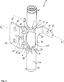
In
Bei der dargestellten Baugruppe
Die Verbindungsstellen
Der Umfangsabschnitt
Der Umfangsabschnitt
Das Befestigungselement
Zwischen dem ersten Befestigungsflansch
Im Übergangsabschnitt
Das dargestellte rohrförmige Gehäuse
Die in
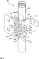
In
In der Ausführungsform gemäß
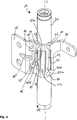
In
In der Ausführungsform gemäß
In der Ausführungsform des Befestigungselements
Zu einer durch den zentralen Punkt
BezugszeichenlisteLIST OF REFERENCE NUMBERS
- 1010
- Baugruppemodule
- 1111
- Verbindungsstellejunction
- 12, 12'12, 12 '
- Befestigungsflanschmounting flange
- 13, 13'13, 13 '
- Befestigungslochmounting hole
- 1414
- BefestigungslanglochMounting slot
- 15, 15'15, 15 '
- ÜbergangsabschnittTransition section
- 16, 16'16, 16 '
- SickeBeading
- 1717
- Beschichtungskanalcoating channel
- 2020
- Gehäusecasing
- 2121
- Oberflächesurface
- 2222
- Oberflächenabschnitt GehäuseSurface section housing
- 3030
- Befestigungselementfastener
- 3131
- Umfangsabschnittperipheral portion
- 3232
- Oberflächesurface
- 3333
- Innenseite UmfangsabschnittInside peripheral portion
- 3434
- Außenseite UmfangsabschnittOutside peripheral section
- 40, 40a, 40b, 40c, 40d, 40e, 40f40, 40a, 40b, 40c, 40d, 40e, 40f
- Durchbruchbreakthrough
- 4141
- Spitzetop
- 4242
- zentraler Punktcentral point
- 4343
- Längelength
- 44 44
- Eckbereichcorner
- 4545
- Aussparungrecess
- 4646
- Spitzetop
- 4747
- Spitzetop
- 50, 50a, 50b, 50c50, 50a, 50b, 50c
- Stegweb
- E1, E2E1, E2
- Erstreckungsebene BefestigungsflanschExtension plane mounting flange
- LL
- Längsrichtung GehäuseLongitudinal housing
- SASA
- Spiegelachsemirror axis
- URUR
- radiale Umfangsrichtungradial circumferential direction
ZITATE ENTHALTEN IN DER BESCHREIBUNG QUOTES INCLUDE IN THE DESCRIPTION
Diese Liste der vom Anmelder aufgeführten Dokumente wurde automatisiert erzeugt und ist ausschließlich zur besseren Information des Lesers aufgenommen. Die Liste ist nicht Bestandteil der deutschen Patent- bzw. Gebrauchsmusteranmeldung. Das DPMA übernimmt keinerlei Haftung für etwaige Fehler oder Auslassungen.This list of the documents listed by the applicant has been generated automatically and is included solely for the better information of the reader. The list is not part of the German patent or utility model application. The DPMA assumes no liability for any errors or omissions.
Zitierte PatentliteraturCited patent literature
- DE 102009012364 A1 [0002] DE 102009012364 A1 [0002]
Claims (12)
Priority Applications (3)
| Application Number | Priority Date | Filing Date | Title |
|---|---|---|---|
| DE102015006898.9A DE102015006898A1 (en) | 2015-06-03 | 2015-06-03 | An assembly of a vehicle safety system, vehicle safety system, vehicle safety device, and method for manufacturing an assembly of a vehicle safety system |
| US15/154,049 US10259415B2 (en) | 2015-06-03 | 2016-05-13 | Subassembly of a vehicle safety system, vehicle safety system, vehicle safety device and method of manufacturing a subassembly of a vehicle safety system |
| CN201610391068.6A CN106240513A (en) | 2015-06-03 | 2016-06-03 | The method of the sub-component of the sub-component of Vehicle security system, Vehicle security system, safety device of vehicle and manufacture Vehicle security system |
Applications Claiming Priority (1)
| Application Number | Priority Date | Filing Date | Title |
|---|---|---|---|
| DE102015006898.9A DE102015006898A1 (en) | 2015-06-03 | 2015-06-03 | An assembly of a vehicle safety system, vehicle safety system, vehicle safety device, and method for manufacturing an assembly of a vehicle safety system |
Publications (1)
| Publication Number | Publication Date |
|---|---|
| DE102015006898A1 true DE102015006898A1 (en) | 2016-12-22 |
Family
ID=57451679
Family Applications (1)
| Application Number | Title | Priority Date | Filing Date |
|---|---|---|---|
| DE102015006898.9A Ceased DE102015006898A1 (en) | 2015-06-03 | 2015-06-03 | An assembly of a vehicle safety system, vehicle safety system, vehicle safety device, and method for manufacturing an assembly of a vehicle safety system |
Country Status (3)
| Country | Link |
|---|---|
| US (1) | US10259415B2 (en) |
| CN (1) | CN106240513A (en) |
| DE (1) | DE102015006898A1 (en) |
Families Citing this family (1)
| Publication number | Priority date | Publication date | Assignee | Title |
|---|---|---|---|---|
| CN106836966A (en) * | 2017-03-24 | 2017-06-13 | 江苏固耐特围栏系统股份有限公司 | A kind of upright fence post and fence system |
Citations (7)
| Publication number | Priority date | Publication date | Assignee | Title |
|---|---|---|---|---|
| DE19631006A1 (en) * | 1996-08-01 | 1998-02-05 | Progress Werk Oberkirch Ag | Gas generator for an airbag and method for producing such a gas generator |
| DE20021673U1 (en) * | 2000-12-21 | 2001-04-26 | TRW Occupant Restraint Systems GmbH & Co. KG, 73553 Alfdorf | Assembly for a vehicle occupant restraint system |
| DE60021467T2 (en) * | 1999-05-05 | 2006-06-14 | Jaguar Cars | Vehicle with a roof-mounted airbag |
| US20060267315A1 (en) * | 2005-05-26 | 2006-11-30 | Trw Vehicle Safety Systems Inc. | Bracket assembly for an inflatable curtain |
| EP2078645A1 (en) * | 2006-10-16 | 2009-07-15 | Autoliv Development Ab | Airbag device for restraining waist part |
| DE102009012364A1 (en) | 2009-03-09 | 2010-09-16 | Trw Airbag Systems Gmbh | Component for use in air bag module of backrest of vehicle, comprises gas generator, which has cylindrical external wall, and thin-walled intermediate element fastened at external wall |
| WO2012147654A1 (en) * | 2011-04-28 | 2012-11-01 | 芦森工業株式会社 | Airbag device |
Family Cites Families (55)
| Publication number | Priority date | Publication date | Assignee | Title |
|---|---|---|---|---|
| ATE73372T1 (en) * | 1986-12-22 | 1992-03-15 | Thyssen Stahl Ag | PROCESS FOR MANUFACTURING A MOLDED BODY FROM SHEET METAL PARTS OF DIFFERENT THICKNESSES. |
| JPH01304083A (en) * | 1988-05-31 | 1989-12-07 | Mazda Motor Corp | Painting method for vehicle outer sheet panel |
| JP2936593B2 (en) * | 1989-08-22 | 1999-08-23 | タカタ株式会社 | Air bag retainer |
| US5257815A (en) * | 1991-10-21 | 1993-11-02 | Trw Vehicle Safety Systems Inc. | Inflator mounting system |
| US5340147A (en) * | 1991-12-19 | 1994-08-23 | Alliedsignal Inc. | Air bag inflator assembly |
| EP0761506B1 (en) * | 1995-09-05 | 2001-10-24 | TRW Occupant Restraint Systems GmbH & Co. KG | Air bag restraint module |
| FR2792592B1 (en) * | 1999-04-20 | 2001-05-18 | Livbag Snc | PROTECTION ASSEMBLY WITH AN EXTERNAL EXPANDABLE DEFLECTOR |
| US6361064B1 (en) * | 1999-12-28 | 2002-03-26 | Delphi Technologies, Inc. | Inflator seal retainer for an air bag module |
| US6559416B1 (en) * | 2000-08-25 | 2003-05-06 | Illinois Tool Works | Alternate current path for mig gun |
| DE10048998C1 (en) * | 2000-09-27 | 2001-12-06 | Freudenberg Carl Fa | Elastic bearing mounting for shaft bearing has buffer of elastic material with V-shaped open fold between shaft bearing and support ring for allowing movement in both axial and radial directions |
| US6435541B1 (en) * | 2000-12-21 | 2002-08-20 | Delphi Technologies, Inc. | Modular air bag housing |
| EP1463652B2 (en) * | 2002-01-04 | 2009-08-19 | TAKATA-PETRI (Ulm) GmbH | Gas flow distributor for a lateral airbag module |
| JP3903801B2 (en) * | 2002-01-28 | 2007-04-11 | タカタ株式会社 | Inflator fixing method and structure, and airbag apparatus |
| US6793241B2 (en) * | 2002-05-01 | 2004-09-21 | Trw Vehicle Safety Systems Inc. | Modular headliner and inflatable curtain assembly |
| US6945554B2 (en) * | 2002-08-26 | 2005-09-20 | Autoliv Asp, Inc. | Inflator press fit housing for inflatable curtains |
| US7097196B2 (en) * | 2002-11-27 | 2006-08-29 | Tk Holdings, Inc. | Modular airbag housing and method of manufacture |
| DE10313242A1 (en) * | 2003-03-25 | 2004-10-14 | Ti Automotive (Heidelberg) Gmbh | Method of earthing a jacketed metal pipe |
| CN100425479C (en) * | 2003-09-03 | 2008-10-15 | 奥托立夫发展公司 | Housing for an airbag device |
| US20050046154A1 (en) * | 2003-09-03 | 2005-03-03 | Rhea Scott L. | Inflatable curtain mounting bracket |
| JP2005096605A (en) * | 2003-09-25 | 2005-04-14 | Toyoda Gosei Co Ltd | Inflator for airbag |
| JP4281644B2 (en) * | 2003-11-21 | 2009-06-17 | 豊田合成株式会社 | Inflator |
| US7384062B2 (en) * | 2004-01-28 | 2008-06-10 | Nihon Plast Co., Ltd. | Airbag system |
| US7419183B2 (en) * | 2004-02-04 | 2008-09-02 | Daicel Chemical Industries, Ltd. | Inflator |
| US7175196B2 (en) * | 2004-02-09 | 2007-02-13 | Trw Vehicle Safety Systems Inc. | Support bracket for an inflatable curtain |
| EP1827918B1 (en) * | 2004-12-22 | 2009-02-18 | Hans Oetiker AG Maschinen- und Apparatefabrik | Clamping ring for fastening a gas generating cartridge |
| DE602006017034D1 (en) * | 2005-02-18 | 2010-11-04 | Key Safety Systems Inc | AIR BAG MODULE |
| JP4736687B2 (en) * | 2005-10-07 | 2011-07-27 | タカタ株式会社 | Inflator mounting structure and wrap anchor |
| US7514153B1 (en) * | 2005-03-03 | 2009-04-07 | The United States Of America As Represented By The Secretary Of The Navy | Method for deposition of steel protective coating |
| EP2001647B1 (en) * | 2006-03-21 | 2013-05-08 | Inteva Products | Method of making an integrated structural member for a vehicle |
| JP4987540B2 (en) * | 2006-04-04 | 2012-07-25 | オートリブ ディベロップメント エイビイ | Side airbag guide plate |
| DE602007010817D1 (en) * | 2006-10-11 | 2011-01-05 | Key Safety Systems Inc | SIDE AIR BAG MODULE |
| US7735853B2 (en) * | 2006-11-22 | 2010-06-15 | Honda Motor Co., Ltd. | Side curtain air bag deflector bracket |
| JP4995679B2 (en) * | 2007-09-19 | 2012-08-08 | タカタ株式会社 | Side airbag device |
| US7661704B2 (en) * | 2007-11-07 | 2010-02-16 | Ford Global Technologies, Llc | Combination grab handle and airbag bracket |
| US7677595B2 (en) * | 2008-01-18 | 2010-03-16 | Autoliv Asp, Inc. | Curtain airbag mounting device |
| JP5154297B2 (en) * | 2008-05-08 | 2013-02-27 | タカタ株式会社 | Curtain airbag bracket and curtain airbag device |
| US20100181746A1 (en) * | 2009-01-16 | 2010-07-22 | Rose Larry D | Airbag module housing |
| US8007000B2 (en) * | 2010-01-07 | 2011-08-30 | Autoliv Asp, Inc. | Inflatable airbag assembly with an inflator bracket |
| US20110221174A1 (en) * | 2010-03-12 | 2011-09-15 | Autoliv Asp, Inc. | Additives for liquid-cooled inflators |
| JP5527534B2 (en) * | 2010-06-11 | 2014-06-18 | スズキ株式会社 | Automobile roof structure |
| US8191927B2 (en) * | 2010-08-17 | 2012-06-05 | Autoliv Asp, Inc. | Liquid cooled inflator |
| DE102010052782A1 (en) * | 2010-11-30 | 2012-05-31 | Trw Automotive Gmbh | Vehicle occupant restraint system for vehicle, comprises gas generator and gas bag, which is connected with gas generator, where gas generator comprises fastening extension |
| CN103842215B (en) * | 2011-05-02 | 2017-05-17 | NxGen技术有限责任公司 | Side curtain airbag and method and appartus for manufacturing a side curtain airbag |
| FR2987621B1 (en) * | 2012-03-02 | 2014-08-22 | Autoliv Dev | GAS GENERATOR FOR AIRBAG |
| US8651519B2 (en) * | 2012-04-09 | 2014-02-18 | Autoliv Asp, Inc. | Seatbelt anchor airbag |
| JP5949521B2 (en) * | 2012-06-26 | 2016-07-06 | 豊田合成株式会社 | Gas generator and airbag device |
| US9333935B2 (en) * | 2012-08-14 | 2016-05-10 | Autoliv Development Ab | Airbag deployment auxiliary member and curtain airbag device |
| DE102012021493A1 (en) * | 2012-10-31 | 2014-04-30 | Daimler Ag | Cross member arrangement and manufacturing method |
| US20140127423A1 (en) * | 2012-11-07 | 2014-05-08 | Dana Automotive Systems Group, Llc | Method for preventing corrosion between two workpieces |
| US9033363B2 (en) * | 2013-03-15 | 2015-05-19 | Autoliv Asp, Inc. | Airbag assemblies with heat shield deflectors |
| US8820779B1 (en) * | 2013-03-15 | 2014-09-02 | Autoliv Asp, Inc. | Inflatable airbag assembly with an internally mounted inflator |
| DE112014003348B4 (en) * | 2013-07-19 | 2017-08-24 | Tk Holdings Inc. | Airbag module and module housing |
| KR20160061190A (en) * | 2014-11-21 | 2016-05-31 | 현대모비스 주식회사 | Airbag Apprartus Of Vehicle |
| KR101655596B1 (en) * | 2014-12-08 | 2016-09-08 | 현대자동차주식회사 | Apparatus for fixing curtain air bag cushion |
| US9573550B1 (en) * | 2015-08-17 | 2017-02-21 | Autoliv Asp, Inc. | Side curtain airbag compression inflator bracket |
-
2015
- 2015-06-03 DE DE102015006898.9A patent/DE102015006898A1/en not_active Ceased
-
2016
- 2016-05-13 US US15/154,049 patent/US10259415B2/en active Active
- 2016-06-03 CN CN201610391068.6A patent/CN106240513A/en active Pending
Patent Citations (7)
| Publication number | Priority date | Publication date | Assignee | Title |
|---|---|---|---|---|
| DE19631006A1 (en) * | 1996-08-01 | 1998-02-05 | Progress Werk Oberkirch Ag | Gas generator for an airbag and method for producing such a gas generator |
| DE60021467T2 (en) * | 1999-05-05 | 2006-06-14 | Jaguar Cars | Vehicle with a roof-mounted airbag |
| DE20021673U1 (en) * | 2000-12-21 | 2001-04-26 | TRW Occupant Restraint Systems GmbH & Co. KG, 73553 Alfdorf | Assembly for a vehicle occupant restraint system |
| US20060267315A1 (en) * | 2005-05-26 | 2006-11-30 | Trw Vehicle Safety Systems Inc. | Bracket assembly for an inflatable curtain |
| EP2078645A1 (en) * | 2006-10-16 | 2009-07-15 | Autoliv Development Ab | Airbag device for restraining waist part |
| DE102009012364A1 (en) | 2009-03-09 | 2010-09-16 | Trw Airbag Systems Gmbh | Component for use in air bag module of backrest of vehicle, comprises gas generator, which has cylindrical external wall, and thin-walled intermediate element fastened at external wall |
| WO2012147654A1 (en) * | 2011-04-28 | 2012-11-01 | 芦森工業株式会社 | Airbag device |
Also Published As
| Publication number | Publication date |
|---|---|
| US10259415B2 (en) | 2019-04-16 |
| CN106240513A (en) | 2016-12-21 |
| US20160355216A1 (en) | 2016-12-08 |
Similar Documents
| Publication | Publication Date | Title |
|---|---|---|
| DE102011085663B4 (en) | Fender boom and body front layout | |
| DE10220025A1 (en) | Cross member for motor vehicle has base body and reinforcement with at least one wall transversely to cross member with aperture for air duct or wiring | |
| DE102013000629A1 (en) | Body structure for vehicle i.e. automobile, has spacer provided between lateral guide flange of first sheet metal part and edge flange of second sheet metal part to form sticking gap with pre-defined gap width | |
| EP1138430A2 (en) | Constructive element, in particular for motor vehicles | |
| EP2477877A1 (en) | Vehicle body construction in the region of the a-pillar and the window crossmember and associated production method | |
| DE29916470U1 (en) | Instrument holder | |
| DE202010018334U1 (en) | Dashboard structure for motor vehicles and motor vehicles having such a structure | |
| DE102017200113A1 (en) | Bumper cross member for a motor vehicle and motor vehicle with such a bumper cross member | |
| DE102018116271A1 (en) | Method of joining | |
| DE19706225C2 (en) | Motor vehicle with a support between the cross member and splash guard | |
| DE102015006898A1 (en) | An assembly of a vehicle safety system, vehicle safety system, vehicle safety device, and method for manufacturing an assembly of a vehicle safety system | |
| DE10101927A1 (en) | Structural component for motor vehicle body consists of two metal semi-shells connected by full-length weld seam along folded flanges | |
| DE102015204917B4 (en) | Side door for a vehicle and vehicle with such a side door | |
| DE102019203450B4 (en) | Body structure for a vehicle | |
| DE202015001448U1 (en) | Vehicle column, in particular A-pillar for a motor vehicle | |
| DE102021102234B3 (en) | Body structure and sheet metal component | |
| DE102015115187A1 (en) | An energy absorbing member for a vehicle and a bumper assembly comprising such a member and a bumper cross member | |
| EP2871116B1 (en) | Molding for motor vehicles | |
| DE102019124020B4 (en) | Bumper cross member for a motor vehicle | |
| EP4342741A1 (en) | Bumper arrangement for a motor vehicle | |
| DE102018117610A1 (en) | Reinforcement structure on a front side of a vehicle cabin | |
| DE102011121401A1 (en) | Automotive body | |
| EP4606681B1 (en) | Connection of an axle support frame with a longitudinal profile | |
| DE202016101547U1 (en) | Stiffening element for a bonnet of a vehicle | |
| DE102015224852A1 (en) | Subframe for a vehicle and method of making a subframe |
Legal Events
| Date | Code | Title | Description |
|---|---|---|---|
| R163 | Identified publications notified | ||
| R081 | Change of applicant/patentee |
Owner name: ZF AIRBAG GERMANY GMBH, DE Free format text: FORMER OWNER: TRW AIRBAG SYSTEMS GMBH, 84544 ASCHAU, DE |
|
| R082 | Change of representative |
Representative=s name: MEHNERT, BERNHARD, DE |
|
| R012 | Request for examination validly filed | ||
| R016 | Response to examination communication | ||
| R002 | Refusal decision in examination/registration proceedings | ||
| R003 | Refusal decision now final |