DE102014225834B4 - Drive chain elongation testing system - Google Patents
Drive chain elongation testing system Download PDFInfo
- Publication number
- DE102014225834B4 DE102014225834B4 DE102014225834.0A DE102014225834A DE102014225834B4 DE 102014225834 B4 DE102014225834 B4 DE 102014225834B4 DE 102014225834 A DE102014225834 A DE 102014225834A DE 102014225834 B4 DE102014225834 B4 DE 102014225834B4
- Authority
- DE
- Germany
- Prior art keywords
- drive chain
- elongation
- detection sensor
- linear actuator
- electronic
- Prior art date
- Legal status (The legal status is an assumption and is not a legal conclusion. Google has not performed a legal analysis and makes no representation as to the accuracy of the status listed.)
- Active
Links
- 238000012360 testing method Methods 0.000 title claims abstract description 27
- 238000001514 detection method Methods 0.000 claims abstract description 33
- 230000007547 defect Effects 0.000 claims abstract 2
- 238000000034 method Methods 0.000 claims description 8
- 238000009434 installation Methods 0.000 claims description 3
- 239000003550 marker Substances 0.000 claims description 2
- 230000008859 change Effects 0.000 description 5
- 238000010586 diagram Methods 0.000 description 5
- 238000004519 manufacturing process Methods 0.000 description 3
- 238000005259 measurement Methods 0.000 description 3
- XEEYBQQBJWHFJM-UHFFFAOYSA-N Iron Chemical compound [Fe] XEEYBQQBJWHFJM-UHFFFAOYSA-N 0.000 description 2
- 238000007796 conventional method Methods 0.000 description 2
- 230000002950 deficient Effects 0.000 description 2
- 238000007689 inspection Methods 0.000 description 2
- 230000003287 optical effect Effects 0.000 description 2
- 230000008569 process Effects 0.000 description 2
- 230000008439 repair process Effects 0.000 description 2
- 230000007423 decrease Effects 0.000 description 1
- 238000009826 distribution Methods 0.000 description 1
- 229910052742 iron Inorganic materials 0.000 description 1
- 238000012986 modification Methods 0.000 description 1
- 230000004048 modification Effects 0.000 description 1
- 238000012544 monitoring process Methods 0.000 description 1
- 230000000737 periodic effect Effects 0.000 description 1
- 230000002085 persistent effect Effects 0.000 description 1
- 238000003860 storage Methods 0.000 description 1
- 238000011179 visual inspection Methods 0.000 description 1
Images


Classifications
-
- B—PERFORMING OPERATIONS; TRANSPORTING
- B65—CONVEYING; PACKING; STORING; HANDLING THIN OR FILAMENTARY MATERIAL
- B65G—TRANSPORT OR STORAGE DEVICES, e.g. CONVEYORS FOR LOADING OR TIPPING, SHOP CONVEYOR SYSTEMS OR PNEUMATIC TUBE CONVEYORS
- B65G43/00—Control devices, e.g. for safety, warning or fault-correcting
- B65G43/02—Control devices, e.g. for safety, warning or fault-correcting detecting dangerous physical condition of load carriers, e.g. for interrupting the drive in the event of overheating
-
- B—PERFORMING OPERATIONS; TRANSPORTING
- B65—CONVEYING; PACKING; STORING; HANDLING THIN OR FILAMENTARY MATERIAL
- B65G—TRANSPORT OR STORAGE DEVICES, e.g. CONVEYORS FOR LOADING OR TIPPING, SHOP CONVEYOR SYSTEMS OR PNEUMATIC TUBE CONVEYORS
- B65G2207/00—Indexing codes relating to constructional details, configuration and additional features of a handling device, e.g. Conveyors
- B65G2207/48—Wear protection or indication features
-
- G—PHYSICS
- G01—MEASURING; TESTING
- G01B—MEASURING LENGTH, THICKNESS OR SIMILAR LINEAR DIMENSIONS; MEASURING ANGLES; MEASURING AREAS; MEASURING IRREGULARITIES OF SURFACES OR CONTOURS
- G01B11/00—Measuring arrangements characterised by the use of optical techniques
- G01B11/02—Measuring arrangements characterised by the use of optical techniques for measuring length, width or thickness
- G01B11/04—Measuring arrangements characterised by the use of optical techniques for measuring length, width or thickness specially adapted for measuring length or width of objects while moving
- G01B11/043—Measuring arrangements characterised by the use of optical techniques for measuring length, width or thickness specially adapted for measuring length or width of objects while moving for measuring length
-
- G—PHYSICS
- G01—MEASURING; TESTING
- G01B—MEASURING LENGTH, THICKNESS OR SIMILAR LINEAR DIMENSIONS; MEASURING ANGLES; MEASURING AREAS; MEASURING IRREGULARITIES OF SURFACES OR CONTOURS
- G01B21/00—Measuring arrangements or details thereof, where the measuring technique is not covered by the other groups of this subclass, unspecified or not relevant
- G01B21/16—Measuring arrangements or details thereof, where the measuring technique is not covered by the other groups of this subclass, unspecified or not relevant for measuring distance of clearance between spaced objects
Landscapes
- Length Measuring Devices With Unspecified Measuring Means (AREA)
- Physics & Mathematics (AREA)
- General Physics & Mathematics (AREA)
- Investigating Strength Of Materials By Application Of Mechanical Stress (AREA)
- Control Of Conveyors (AREA)
Abstract
Antriebskettenlängungsprüfsystem, umfassend:eine Antriebskette, die eingerichtet ist, in ihrer Längserstreckungsrichtung bewegt zu werden; undeine Steuerung, die einen Prozessor und einen Speicher aufweist, und die eingerichtet ist:eine Längung der Antriebskette unter Verwendung einer Messvorrichtung zu messen; undFehler auf der Antriebskette unter Verwendung einer Anbringvorrichtung für elektronische Markierungen zu markieren, wobei die Messvorrichtung beinhaltet:einen Erfassungssensor für die horizontale Richtung, der nahe der Antriebskette angeordnet ist, und eingerichtet ist, eine Längung der Antriebskette zu messen; undeinen Erfassungssensor für die vertikale Richtung, der unter der Antriebskette angeordnet ist.A drive chain elongation testing system comprising: a drive chain configured to be moved in its longitudinal direction; anda controller which has a processor and a memory and which is configured to: measure an elongation of the drive chain using a measuring device; andmarking defects on the drive chain using an electronic mark applying device, the measuring device including: a horizontal direction detection sensor disposed near the drive chain and configured to measure an elongation of the drive chain; anda vertical direction detection sensor disposed under the drive chain.
Description
Die vorliegende Erfindung bezieht sich auf ein Antriebskettenlängungsprüfsystem und insbesondere auf ein Antriebskettenlängungsprüfsystem für eine Antriebskette, die einen Anhänger oder einen Lastkraftwagen bewegt, um einen Schaden an der Antriebskette zu vermeiden.The present invention relates to a drive chain elongation testing system and, more particularly, to a drive chain elongation testing system for a drive chain moving a trailer or truck to prevent damage to the drive chain.
Im Allgemeinen werden Anlagen, die Produkte zwischen Prozessen bewegen, in Industrieanlagen verwendet. Ein repräsentatives Beispiel für diese Anlagen ist eine doppelt wirkende Hängebahn (double action type trolley conveyor). Die doppelt wirkende Hängebahn beinhaltet eine Arbeitsschiene, die eine darin angeordnete Antriebskette aufweist, die ein Kettenschleppelement und ein Hängeschleppelement, das unter der Arbeitsschiene angeordnet, mit dem Hängeschleppelement gekoppelt ist und bewegt wird, während es von der Arbeitsschiene gehalten wird, aufweist.In general, equipment that moves products between processes is used in industrial plants. A representative example of these systems is a double-action type trolley conveyor. The double-acting overhead conveyor includes a work rail having a drive chain disposed therein, which has a chain towing element and a hanging towing element, which is positioned below the work rail, is coupled to the hanging towing element and is moved while it is held by the work rail.
Wenn die doppelt wirkende Hängebahn für eine beträchtliche Zeitspanne betrieben wird, oder das Gewicht eines Produktes, das vom dem Hängeschleppelement aufgenommen ist, relativ schwer ist, kann sich die Antriebskette verformen (z.B. unbrauchbar werden). Wenn die Antriebskette deutlich verformt ist, wird der Betrieb gestoppt und es ist erforderlich, die Antriebskette zu vermessen.If the double-acting overhead conveyor is operated for a considerable period of time, or if the weight of a product picked up by the overhead towing element is relatively heavy, the drive chain can deform (e.g. become unusable). If the drive chain is significantly deformed, the operation is stopped and it is necessary to measure the drive chain.
Ein Bediener misst die Verformung der Antriebskette manuell oder misst die Verformung der Antriebskette unter Verwendung einer optischen Untersuchung, einer Codierzählung (encoder count) oder dergleichen. Jedoch misst ein Bediener, wenn er die Verformung der Antriebskette manuell misst, eine Längenänderung der Antriebskette mit einem Bandmaß, was einen periodischen Stillstand der Produktionslinie verursacht. Insbesondere kann die Längenänderung der Antriebskette nicht während einem Betrieb der Anlage in Echtzeit gemessen werden und separate Werkzeug sind erforderlich.An operator manually measures the deformation of the drive chain or measures the deformation of the drive chain using an optical inspection, an encoder count, or the like. However, when an operator manually measures the deformation of the drive chain, he measures a change in length of the drive chain with a tape measure, which causes a periodic standstill of the production line. In particular, the change in length of the drive chain cannot be measured in real time while the system is in operation, and separate tools are required.
Ferner kann eine Prüfgenauigkeit bedingt durch die Lichtverhältnisse am Arbeitsplatz und eine Form der Antriebskette verringert sein, wenn ein visuelles Prüfverfahren angewendet wird. Ergänzend kann die verringerte Genauigkeit Fehler im Hinblick auf die gemessenen Werte verursachen. Ferner treten Codierzählungsfehler (encoder count errors) basierend auf dem Wechsel in der Reibkraft auf.Furthermore, if a visual inspection method is used, inspection accuracy may be reduced due to the lighting conditions in the workplace and a shape of the drive chain. In addition, the reduced accuracy can cause errors with regard to the measured values. Furthermore, encoder count errors occur based on the change in the frictional force.
Gemäß dem konventionellen Verfahren zum Messen der Verformung der Antriebskette kann es erforderlich sein, einen ganzen Abschnitt einer Antriebskette auszutauschen, da es beinahe unmöglich sein kann, einen im Wesentlichen verformten Abschnitt der Antriebskette zu bestimmten. Ergänzend kann es schwierig sein, die Antriebskette zu warten und zu reparieren. Insbesondere, da das konventionelle Verfahren eine Längung auf Gliedbasis in einer einzelnen Richtung misst, kann es schwierig sein, einen stark verformten Abschnitt der Antriebskette zu entfernen.According to the conventional method of measuring the deformation of the drive chain, it may be necessary to replace an entire section of a drive chain because it may be almost impossible to determine a substantially deformed section of the drive chain. In addition, the drive chain can be difficult to maintain and repair. In particular, since the conventional method measures link-based elongation in a single direction, it may be difficult to remove a severely deformed portion of the drive chain.
Ferner offenbart die
Die vorher genannten und weiter Ziele, Merkmale und Vorteile der vorliegenden Offenbarung werden aus der nachfolgenden detaillierten Beschreibung in Zusammenhang mit den beigefügten Zeichnungen noch offensichtlicher:
-
1 ist eine schematische Darstellung, die ein Antriebskettenlängungsprüfsystem gemäß einer beispielhaften Ausführungsform der vorliegenden Offenbarung zeigt; -
2 ist eine schematische Darstellung, die eine Messung einer Antriebskette mit einem Antriebskettenlängungsprüfsystem von1 gemäß einer beispielhaften Ausführungsform der vorliegenden Offenbarung zeigt; -
3 ist eine schematische Darstellung, die eine Verteilung von einer Mehrzahl von Antriebsketten, die in dem Antriebskettenlängungsprüfsystem von1 beinhaltet sind, gemäß einer beispielhaften Ausführungsform der vorliegenden Offenbarung zeigt; -
4 ist eine schematische Darstellung, die eine Anbringungsvorrichtung für elektronische Markierungen, die in dem Antriebskettenlängungsprüfsystem von1 beinhaltet ist, gemäß einer beispielhaften Ausführungsform der vorliegenden Offenbarung zeigt; und -
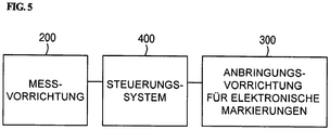
5 ist ein schematisches Blockdiagramm von einem Steuerungssystem, das in dem Antriebskettenlängungsprüfsystem von1 enthalten ist, gemäß einer beispielhaften Ausführungsform der vorliegenden Offenbarung.
-
1 Fig. 3 is a schematic diagram showing a drive chain elongation testing system in accordance with an exemplary embodiment of the present disclosure; -
2 FIG. 13 is a schematic diagram showing a measurement of a drive chain with the drive chain elongation testing system of FIG1 according to an exemplary embodiment of the present disclosure; -
3 FIG. 13 is a schematic diagram showing a distribution of a plurality of drive chains used in the drive chain elongation testing system of FIG1 according to an exemplary embodiment of the present disclosure; -
4th FIG. 13 is a schematic diagram illustrating an electronic mark applicator used in the drive chain elongation testing system of FIG1 is included, according to an exemplary embodiment of the present disclosure; and -
5 FIG. 13 is a schematic block diagram of a control system used in the drive chain elongation testing system of FIG1 is included, according to an exemplary embodiment of the present disclosure.
Obwohl eine beispielhafte Ausführungsform beschrieben wird, wobei eine Mehrzahl von Einheiten verwendet werden kann, ein beispielhaftes Verfahren durchzuführen, wird es so verstanden, dass beispielhafte Verfahren auch durch eines oder eine Mehrzahl von Modulen durchgeführt werden können. Ergänzend wird es so verstanden, dass der Ausdruck Steuerung/Steuerungseinheit sich auf eine Hardware-Vorrichtung bezieht, die einen Speicher und einen Prozessor beinhaltet. Der Speicher ist eingerichtet, die Module zu speichern und der Prozessor ist insbesondere eingerichtet, diese Module auszuführen, um eines oder mehrere Verfahren auszuführen, die weiter unten beschrieben sind.While an exemplary embodiment is described wherein a plurality of units can be used to perform an exemplary method, it is understood that exemplary methods can also be performed by one or a plurality of modules. In addition, it is understood that the term control / control unit relates to a hardware device that includes a memory and a processor. The memory is set up to store the modules and the processor is set up, in particular, to execute these modules in order to execute one or more methods which are described below.
Ferner kann eine Steuerungslogik der vorliegenden Erfindung als dauerhafte von einem Computer lesbare Medie auf einem von einem Computer lesbaren Medium realisiert sein, das ausführbare Programmanweisungen zur Ausführung auf einem Prozessor, einem Controller/Steuerung oder dergleichen beinhaltet. Beispiele des von einem Computer lesbaren Mediums beinhalten, sind aber nicht beschränkt, ROM, RAM, (CD)-ROM, Magnetbänder, Floppy Discs, Flash-Laufwerke, Speicherkarten und optische Speichermedien. Das von einem Computer lesbare Medium kann auch in einem Computernetzwerk verteilt sein, so dass die von einem Computer lesbaren Programmanweisungen auf verteilte Art und Weise gespeichert und ausgeführt werden können, z.B. durch einen Telematics Server oder ein Controller Area Network (CAN).Furthermore, control logic of the present invention can be implemented as persistent computer-readable media on a computer-readable medium that includes executable program instructions for execution on a processor, controller or the like. Examples of the computer readable medium include, but are not limited to, ROM, RAM, (CD) -ROM, magnetic tapes, floppy discs, flash drives, memory cards, and optical storage media. The computer-readable medium can also be distributed in a computer network, so that the program instructions readable by a computer can be stored and executed in a distributed manner, e.g. by a telematics server or a controller area network (CAN).
Die Terminologie, wie sie hier verwendet wird, dient dem Zweck, lediglich bestimmte Ausführungsformen zu beschreiben und ist nicht angedacht, die Erfindung zu beschränken. Wie sie hier verwendet werden, sind die Singularformen „ein“, „der“, „die“ vorgesehen, die Pluralformen ebenfalls einzuschließen, wenn es der Text nicht klar anders angibt. Es soll ferner verstanden sein, dass der Ausdruck „umfassen“ und/oder „umfassend“, wenn sie in dieser Beschreibung verwendet werden, das Vorhandensein von angegebenen Merkmalen, Zahlenwerten, Schritten, Arbeitsvorgängen, Elementen und/oder Komponenten angeben, aber nicht das Vorhandensein oder die Ergänzung von einem oder mehreren anderen Merkmalen, Zahlenwerten, Schritten, Arbeitsvorgängen, Elementen und/oder Komponenten oder Gruppen davon ausschließen. Wie hier verwendet, beinhaltet der Ausdruck „und/oder“ alle Kombinationen von einem oder mehreren der zugeordnet aufgelisteten Dinge.As used herein, the terminology is used to describe only certain embodiments and is not intended to limit the invention. As used herein, the singular forms “a”, “the”, “the” are intended to include the plural forms as well, unless the text clearly indicates otherwise. It is further to be understood that the term “comprise” and / or “comprising”, when used in this description, indicate the presence of specified features, numerical values, steps, operations, elements and / or components, but not the presence or exclude the addition of one or more other characteristics, numerical values, steps, work processes, elements and / or components or groups thereof. As used herein, the term “and / or” includes any combination of one or more of the associated listed items.
Im Folgenden werden beispielhafte Ausführungsformen der vorliegenden Offenbarung im Detail unter Bezugnahme auf die beigefügten Zeichnungen beschrieben.In the following, exemplary embodiments of the present disclosure will be described in detail with reference to the accompanying drawings.
Wie in den
Die Messvorrichtung
Gemäß einer beispielhaften Ausführungsform der vorliegenden Offenbarung kann das Antriebskettenlängungsprüfsystem vier Bilderfassungssensoren beinhalten, ist jedoch nicht darauf beschränkt. Mit anderen Worten, zwei Erfassungssensoren für die horizontale Richtung
Insbesondere, wenn der Abstand zwischen den beiden Erfassungssensoren für die vertikale Richtung
Die Erfassungssensoren für die vertikale Richtung
Gemäß einer beispielhaften Ausführungsform der vorliegenden Offenbarung können drei Antriebsketten
Die Anbringungsvorrichtung für elektronische Markierungen
Gemäß der vorliegenden Offenbarung kann das Antriebskettenlängungsprüfsystem zusätzlich ein Steuerungssystem


Wenn der gemessene Abstand und die Längung im Hinblick auf Referenzwerte nicht zufrieden stellend sind (z.B. größer sind), kann das Steuerungssystem
Obwohl die vorliegende Offenbarung mit Bezug auf beispielhafte Ausführungsformen und die beigefügten Zeichnungen beschrieben wurde, soll für den Fachmann angemerkt sein, dass die vorliegende Offenbarung nicht darauf beschränkt ist, sondern dass verschiedene Modifikationen und Änderungen gemacht werden können, ohne von dem Schutzbereich, wie er in den nachfolgenden Ansprüchen festgelegt ist, abzuweichen.Although the present disclosure has been described with reference to exemplary embodiments and the accompanying drawings, it should be noted for those skilled in the art that the present disclosure is not limited thereto, but that various modifications and changes can be made without departing from the scope shown in FIG the following claims is set to deviate.
BezugszeichenlisteList of reference symbols
- 100100
- AntriebsketteDrive chain
- 110110
- KettenschleppelementChain drag element
- 200200
- MessvorrichtungMeasuring device
- 210210
- Erster LinearaktorFirst linear actuator
- 220220
- Zweiter LinearaktorSecond linear actuator
- 230230
- Dritter LinearaktorThird linear actuator
- 300300
- Anbringungsvorrichtung für elektronische MarkierungenApplicator for electronic markings
- 310310
- Elektronische MarkierungElectronic marking
- 320320
- BewegungsarmPoor movement
- 330330
- Installationsteil für den BewegungsarmInstallation part for the movement arm
- 331331
- Pneumatischer ZylinderPneumatic cylinder
- 340340
- Gehäusecasing
- 341341
- Magazinmagazine
- 342342
- DruckaufbringarmPressure application arm
- 343343
- Motorengine
- 400400
- SteuerungssystemControl system
- S1S1
- Erfassungssensor für die vertikal RichtungDetection sensor for the vertical direction
- S2S2
- Erfassungssensor für die horizontale RichtungDetection sensor for the horizontal direction
Claims (12)
Applications Claiming Priority (2)
| Application Number | Priority Date | Filing Date | Title |
|---|---|---|---|
| KR10-2014-0128680 | 2014-09-25 | ||
| KR1020140128680A KR101610517B1 (en) | 2014-09-25 | 2014-09-25 | Elongation check system for power chain |
Publications (2)
| Publication Number | Publication Date |
|---|---|
| DE102014225834A1 DE102014225834A1 (en) | 2016-03-31 |
| DE102014225834B4 true DE102014225834B4 (en) | 2021-08-26 |
Family
ID=55485828
Family Applications (1)
| Application Number | Title | Priority Date | Filing Date |
|---|---|---|---|
| DE102014225834.0A Active DE102014225834B4 (en) | 2014-09-25 | 2014-12-15 | Drive chain elongation testing system |
Country Status (3)
| Country | Link |
|---|---|
| US (1) | US9790034B2 (en) |
| KR (1) | KR101610517B1 (en) |
| DE (1) | DE102014225834B4 (en) |
Cited By (1)
| Publication number | Priority date | Publication date | Assignee | Title |
|---|---|---|---|---|
| DE102024125072A1 (en) | 2024-09-03 | 2026-03-05 | Rotec Gmbh | Device and method for the non-destructive magnetic testing of a chain |
Families Citing this family (4)
| Publication number | Priority date | Publication date | Assignee | Title |
|---|---|---|---|---|
| DE102016015364A1 (en) * | 2016-12-16 | 2018-07-05 | Technische Universität Ilmenau | Method and arrangement for determining the geometric characteristics of chain links and link chains |
| DE102018119466A1 (en) * | 2018-08-09 | 2020-02-13 | Iwis Antriebssysteme Gmbh & Co. Kg | Device and method for determining the state of wear of a chain |
| EP3647239B1 (en) | 2018-10-30 | 2023-08-16 | John Bean Technologies Corporation | Systems and methods for chain wear elongation measurement and drive compensation |
| CN117228227B (en) * | 2023-09-11 | 2024-04-02 | 中国矿业大学 | An intelligent monitoring and winding device and control method for heavy-duty mining scraper conveyor |
Citations (2)
| Publication number | Priority date | Publication date | Assignee | Title |
|---|---|---|---|---|
| US20110093218A1 (en) | 2009-10-20 | 2011-04-21 | Tibor Vozner | Conveyor chain monitoring system and method |
| US20110093288A1 (en) | 2004-03-05 | 2011-04-21 | Health Outcomes Sciences, Llc | Systems and methods for risk stratification of patient populations |
Family Cites Families (22)
| Publication number | Priority date | Publication date | Assignee | Title |
|---|---|---|---|---|
| US3926125A (en) * | 1974-02-20 | 1975-12-16 | Redman Fisher Eng Ltd | Power and free conveyor |
| HU180827B (en) * | 1979-08-10 | 1983-04-29 | Koezponti Banyaszati Fejleszte | Method for measuring the resistance to wear of endless driving devices during operation |
| US5289666A (en) * | 1986-03-20 | 1994-03-01 | T. W. Hamilton Design Ltd. | Apparatus for applying label tags |
| US5490590A (en) * | 1995-03-17 | 1996-02-13 | Courtney; David | Chain wear monitor |
| US5563392A (en) * | 1995-04-12 | 1996-10-08 | Patco Sales & Service, Inc. | Method and apparatus for monitoring wear of a continuous chain |
| JP3570914B2 (en) | 1999-04-07 | 2004-09-29 | 株式会社日立ビルシステム | Chain elongation diagnostic device |
| US6434914B1 (en) * | 1999-11-01 | 2002-08-20 | Bouldin & Lawson, Inc. | Tag placement apparatus |
| JP2001158587A (en) | 1999-12-02 | 2001-06-12 | Mitsubishi Electric Building Techno Service Co Ltd | Measuring device for quantity of sag of passenger conveyor chain and its measuring method |
| KR200317471Y1 (en) | 2003-03-18 | 2003-06-25 | 주식회사 세계로시스템 | Chain abnormal circumstances detecting apparatus of sewage works |
| GB2400090B (en) * | 2003-04-05 | 2006-04-19 | Renold Plc | Chain wear monitoring method and apparatus |
| KR100559456B1 (en) | 2003-06-19 | 2006-03-10 | 김병철 | Elongation measuring device of chain conveyor |
| KR100617419B1 (en) | 2003-12-19 | 2006-08-30 | 오티스 엘리베이터 컴파니 | Low noise chain abnormality detection device |
| JP2006250582A (en) * | 2005-03-08 | 2006-09-21 | Hitachi Plant Technologies Ltd | RFID tag with load sensor |
| JP5052837B2 (en) | 2006-08-08 | 2012-10-17 | 三菱電機株式会社 | Chain abnormality diagnosis device |
| JP2009156341A (en) | 2007-12-26 | 2009-07-16 | Jtekt Corp | Chain abnormality monitoring device |
| US7793775B2 (en) * | 2008-06-24 | 2010-09-14 | Pitney Bowes Inc. | Method and apparatus for determining wear of a continuous chain |
| JP5283608B2 (en) * | 2009-11-30 | 2013-09-04 | 株式会社椿本チエイン | Extension degree measuring device, extension degree measuring system, and computer program |
| FR2986815B1 (en) * | 2012-02-13 | 2014-12-19 | Micro Controle Spectra Physics | DEVICE AND SYSTEM FOR ALIGNMENT AND MAINTENANCE IN POSITION OF BEAMS. |
| KR20140089966A (en) | 2013-01-08 | 2014-07-16 | 정보통신산업진흥원 | Automatically Attached Device for Tire RFID Tags |
| KR101517003B1 (en) | 2013-04-29 | 2015-05-04 | 이영로 | Teaching meterials for divisor and multiple |
| US9683918B2 (en) * | 2014-01-14 | 2017-06-20 | Toyota Motor Engineering & Manufacturing North America, Inc. | Wear detection systems for overhead conveyor systems |
| DE202014100540U1 (en) * | 2014-02-07 | 2014-03-20 | Igus Gmbh | Energy guiding chain and monitoring system for protection against cable breakage |
-
2014
- 2014-09-25 KR KR1020140128680A patent/KR101610517B1/en not_active Expired - Fee Related
- 2014-12-13 US US14/569,644 patent/US9790034B2/en not_active Expired - Fee Related
- 2014-12-15 DE DE102014225834.0A patent/DE102014225834B4/en active Active
Patent Citations (2)
| Publication number | Priority date | Publication date | Assignee | Title |
|---|---|---|---|---|
| US20110093288A1 (en) | 2004-03-05 | 2011-04-21 | Health Outcomes Sciences, Llc | Systems and methods for risk stratification of patient populations |
| US20110093218A1 (en) | 2009-10-20 | 2011-04-21 | Tibor Vozner | Conveyor chain monitoring system and method |
Cited By (1)
| Publication number | Priority date | Publication date | Assignee | Title |
|---|---|---|---|---|
| DE102024125072A1 (en) | 2024-09-03 | 2026-03-05 | Rotec Gmbh | Device and method for the non-destructive magnetic testing of a chain |
Also Published As
| Publication number | Publication date |
|---|---|
| KR20160036421A (en) | 2016-04-04 |
| US9790034B2 (en) | 2017-10-17 |
| KR101610517B1 (en) | 2016-04-07 |
| US20160090244A1 (en) | 2016-03-31 |
| DE102014225834A1 (en) | 2016-03-31 |
Similar Documents
| Publication | Publication Date | Title |
|---|---|---|
| DE102014225834B4 (en) | Drive chain elongation testing system | |
| EP2076458B1 (en) | Device for monitoring a conveying system | |
| EP2710332B1 (en) | Apparatus and method for measuring the stretch of a chain which circulates endlessly in the apparatus | |
| DE102007029299B4 (en) | Optical sensor for positioning tasks | |
| DE102014106312A1 (en) | Method for testing a rivet | |
| DE102010023736A1 (en) | Robot system with problem detection function | |
| DE102016006252A1 (en) | Manufacturing system with a robot having a position correction function | |
| DE102019101005B4 (en) | Object conveyor system | |
| DE102017119301A1 (en) | Device and method for determining the state of wear of a chain | |
| DE102014110548A1 (en) | Robotic arm system and method for calibrating parallelism | |
| EP1593930A1 (en) | Apparatus and method for measuring objects | |
| DE102009053874A1 (en) | Robot for automatic 3D measurement and procedure | |
| DE102004007830A1 (en) | Localization and marking method for faults on car bodies in which fault locations are determined by comparing electronically stored construction data with images recorded using an optical recording arrangement | |
| DE102020128435A1 (en) | Diagnostic device | |
| DE102013009127A1 (en) | Measuring system for measuring material thickness and corrosion rate of e.g. pipe, transmits measurement data of ultrasound measuring unit and space coordinate data from three-dimensional tracking system as combined data sets | |
| DE102017213444B4 (en) | Method and apparatus for inspecting a positioning machine using a laser tracking interferometer | |
| DE102008019435A1 (en) | Method for contact less measurement of three-dimensional, complex molded components, involves collecting measuring component by fixture and recording is done in alignment of component with camera or other optical image recording devices | |
| DE102014215321A1 (en) | Robot system and method for calibrating axes of a robot | |
| DE102019122049A1 (en) | Method for receiving or changing a probe head or sensor on a quill or on an interface of a coordinate measuring machine arranged on the quill | |
| DE112009001353T5 (en) | A method of calibrating the position of blades of a slitter in a fiber web machine and apparatus using the method | |
| DE102009027966A1 (en) | Sprit level e.g. water level, for marking mounting points at workpiece i.e.wall, has marking device for marking mounting points, and controller with keyboard for inputting data for points and connected with device for activating device | |
| DE102023203327A1 (en) | Method for improving the measurement when performing an alignment of shafts of a first machine and a second machine | |
| DE102022126380A1 (en) | Method for applying a marking to a surface of a component, robot system, method for adapting a virtual target geometry and computer program product | |
| DE102007017675A1 (en) | Component e.g. body component, measuring device e.g. coordinate measuring machine, has data processing unit, where three dimensional model of component is evaluated by unit and integrated computer program from detected frames of component | |
| DE102010026891A1 (en) | Device for measuring objects |
Legal Events
| Date | Code | Title | Description |
|---|---|---|---|
| R012 | Request for examination validly filed | ||
| R016 | Response to examination communication | ||
| R018 | Grant decision by examination section/examining division | ||
| R020 | Patent grant now final |