DE102014221235A1 - Method for detecting a trailer of a tractor vehicle - Google Patents
Method for detecting a trailer of a tractor vehicle Download PDFInfo
- Publication number
- DE102014221235A1 DE102014221235A1 DE102014221235.9A DE102014221235A DE102014221235A1 DE 102014221235 A1 DE102014221235 A1 DE 102014221235A1 DE 102014221235 A DE102014221235 A DE 102014221235A DE 102014221235 A1 DE102014221235 A1 DE 102014221235A1
- Authority
- DE
- Germany
- Prior art keywords
- state
- trailer
- lamp
- load
- stop
- Prior art date
- Legal status (The legal status is an assumption and is not a legal conclusion. Google has not performed a legal analysis and makes no representation as to the accuracy of the status listed.)
- Granted
Links
Images
Classifications
-
- B—PERFORMING OPERATIONS; TRANSPORTING
- B60—VEHICLES IN GENERAL
- B60D—VEHICLE CONNECTIONS
- B60D1/00—Traction couplings; Hitches; Draw-gear; Towing devices
- B60D1/24—Traction couplings; Hitches; Draw-gear; Towing devices characterised by arrangements for particular functions
-
- B—PERFORMING OPERATIONS; TRANSPORTING
- B60—VEHICLES IN GENERAL
- B60D—VEHICLE CONNECTIONS
- B60D1/00—Traction couplings; Hitches; Draw-gear; Towing devices
- B60D1/58—Auxiliary devices
- B60D1/62—Auxiliary devices involving supply lines, electric circuits or the like
-
- B—PERFORMING OPERATIONS; TRANSPORTING
- B60—VEHICLES IN GENERAL
- B60R—VEHICLES, VEHICLE FITTINGS, OR VEHICLE PARTS, NOT OTHERWISE PROVIDED FOR
- B60R16/00—Electric or fluid circuits specially adapted for vehicles and not otherwise provided for; Arrangement of elements of electric or fluid circuits specially adapted for vehicles and not otherwise provided for
- B60R16/02—Electric or fluid circuits specially adapted for vehicles and not otherwise provided for; Arrangement of elements of electric or fluid circuits specially adapted for vehicles and not otherwise provided for electric constitutive elements
- B60R16/023—Electric or fluid circuits specially adapted for vehicles and not otherwise provided for; Arrangement of elements of electric or fluid circuits specially adapted for vehicles and not otherwise provided for electric constitutive elements for transmission of signals between vehicle parts or subsystems
-
- B—PERFORMING OPERATIONS; TRANSPORTING
- B60—VEHICLES IN GENERAL
- B60Q—ARRANGEMENT OF SIGNALLING OR LIGHTING DEVICES, THE MOUNTING OR SUPPORTING THEREOF OR CIRCUITS THEREFOR, FOR VEHICLES IN GENERAL
- B60Q11/00—Arrangement of monitoring devices for devices provided for in groups B60Q1/00 - B60Q9/00
-
- G—PHYSICS
- G01—MEASURING; TESTING
- G01R—MEASURING ELECTRIC VARIABLES; MEASURING MAGNETIC VARIABLES
- G01R19/00—Arrangements for measuring currents or voltages or for indicating presence or sign thereof
- G01R19/0092—Measuring current only
-
- G—PHYSICS
- G01—MEASURING; TESTING
- G01R—MEASURING ELECTRIC VARIABLES; MEASURING MAGNETIC VARIABLES
- G01R19/00—Arrangements for measuring currents or voltages or for indicating presence or sign thereof
- G01R19/145—Indicating the presence of current or voltage
- G01R19/15—Indicating the presence of current
-
- G—PHYSICS
- G01—MEASURING; TESTING
- G01R—MEASURING ELECTRIC VARIABLES; MEASURING MAGNETIC VARIABLES
- G01R31/00—Arrangements for testing electric properties; Arrangements for locating electric faults; Arrangements for electrical testing characterised by what is being tested not provided for elsewhere
- G01R31/005—Testing of electric installations on transport means
- G01R31/006—Testing of electric installations on transport means on road vehicles, e.g. automobiles or trucks
- G01R31/007—Testing of electric installations on transport means on road vehicles, e.g. automobiles or trucks using microprocessors or computers
Landscapes
- Engineering & Computer Science (AREA)
- Mechanical Engineering (AREA)
- Physics & Mathematics (AREA)
- General Physics & Mathematics (AREA)
- Transportation (AREA)
- Chemical & Material Sciences (AREA)
- Combustion & Propulsion (AREA)
- Lighting Device Outwards From Vehicle And Optical Signal (AREA)
Abstract
Ein Verfahren des Erkennens eines Anhängers eines Zugmaschinenfahrzeugs durch eine elektronische Steuereinheit (ECU) beinhaltet: Bestimmen, ob ein Parkschalter in einem Ein-Zustand ist und ein Getriebegangzustand ein Parkzustand ist. Ob ein Stopplampenschalter in einem Ein-Zustand und ein Zustand eines Stromes, welcher in der Stopplampe des Anhängers fließt, in einem Ein-Zustand ist, wird bestimmt. Eine Laststrommenge einer Lastlampe wird erkannt, und ob die Stopplampe in einem „offenen” Zustand ist, wird bestimmt. Ein Modus für einen Anhänger-Nicht-Anschluss-Modus, wenn die Stopplampe in einem Aus-Zustand ist, wird bestimmt.A method of recognizing a trailer of a tractor vehicle by an electronic control unit (ECU) includes: determining whether a parking switch is in an on state and a transmission state is a parking state. Whether a stop lamp switch in an on state and a state of a current flowing in the trailer stop lamp is in an on state is determined. A load current amount of a load lamp is detected, and whether the stop lamp is in an "open" state is determined. A trailer non-port mode of operation when the stop lamp is in an off state is determined.
Description
TECHNISCHER BEREICHTECHNICAL PART
Die vorliegende Offenbarung bezieht sich auf ein Verfahren des Erkennens eines Anhängers eines Zugmaschinenfahrzeugs, und spezieller ausgedrückt, auf ein Verfahren des Erkennens eines Anhängers, welches eine Laststrommenge erkennt, welche in eine Lastlampe fließt, wie zum Beispiel eine Stopplampe und eine Abbiegesignallampe der linken Seite der Zugmaschine, durch das Benutzen eines intelligenten Leistungsschalter-(IPS-)Elementes, welches in einer intelligenten Anschlussdose (SJB) einer Zugmaschine befestigt ist.The present disclosure relates to a method of recognizing a trailer of a tractor vehicle, and more particularly, to a method of detecting a trailer recognizing a load current amount flowing in a load lamp, such as a stop lamp and a left side turn signal lamp Tractor, by using an intelligent circuit breaker (IPS) element, which is mounted in a smart junction box (SJB) of a tractor.
HINTERGRUNDBACKGROUND
Im Allgemeinen bezieht sich eine Zugmaschine auf ein Fahrzeug, welches einen Anhänger zieht, welcher am hinteren Ende des Fahrzeugs zum Fahren angekoppelt ist.In general, a tractor refers to a vehicle that tows a trailer that is coupled to the rear end of the vehicle for driving.
Eine Abbiegesignallampe ist auf der Zugmaschine entsprechend der Automobilsicherheitsgesetze befestigt, und sie ist ein Sicherheitssignalgerät, welches anderen Fahrzeugen hilft, genau die Zugmaschine zu erkennen, welche eine Anhängerdrehung besitzt bzw. durchführt.A turn signal lamp is mounted on the tractor in accordance with the automobile safety laws, and is a safety signal device that helps other vehicles accurately recognize the tractor that has trailer rotation.
Wenn die Abbiegesignallampe unterbrochen bzw. abgeschaltet ist, um einen Fehler bzw. ein Versagen der Abbiegesignallampe anzuzeigen, warnt die Abbiegesignallampe einen Fahrer über das Abgeschaltetsein der Abbiegesignallampe durch ein Flackersignal an einem Armaturenbrett der Zugmaschine mit einer Geschwindigkeit von 120 bis 250 Mal pro Minute, welches mehr als 85 mal pro Minute in einem normalen Zustand ist.When the turn signal lamp is turned off to indicate a turn signal lamp failure, the turn signal lamp warns a driver of the turn signal lamp being turned off by a flickering signal on a tractor dashboard at a speed of 120 to 250 times per minute is more than 85 times per minute in a normal state.
Jedoch kann sogar in dem Fall, bei welchem die Zugmaschine nicht an dem hinteren Bereich der Zugmaschine angeschlossen ist, eine elektronische Steuereinheit (ECU) der Zugmaschine den Nicht-Anschluss-Zustand des Anhängers als das Abgeschaltetsein der Abbiegesignallampe fehlinterpretieren, um den Fehler anzuzeigen.However, even in the case where the tractor is not connected to the rear portion of the tractor, an electronic control unit (ECU) of the tractor may misinterpret the trailer non-connection state as the turn-off of the turn signal lamp to indicate the failure.
Es besteht ein Bedarf für die Entwicklung eines Verfahrens des genauen In-Kenntnis-Setzens eines Fahrers, ob ein Anhänger angeschlossen ist, um den Fahrer davor zu bewahren, dass er einen Nicht-Anschluss-Zustand des Anhängers als ein Abgeschaltetsein einer Abbiegesignallampe erkennt. Innerhalb der öffentlich bekannten Technologie, um die zuvor erwähnte Funktion im Stand der Technik bereitzustellen, gibt es eine Technologie des Aufbauens des Luftdetektierschalters in einer Druckluftleitung, welche Druckluft für den Anhänger liefert, und des Bestimmens, ob der Anhänger über die Luftdruckdetektierschaltung angekoppelt ist. Eine Technologie des Erkennens durch die ECU, ob der Anhänger angekoppelt ist, durch das Hinzufügen eines Pull-down-Widerstands und einer Detektierschaltung zu einer Anhängerlampe-Kanalschaltung, ist verfügbar. Jedoch erfordern die zuvor erwähnten Technologien zusätzliche Kosten für das Aufbauen des Luftdruck-Detektierschalters und des Pull-down-Widerstands und der Detektierschaltung, so dass dadurch die Produktionskosten erhöht werden.There is a need for developing a method of accurately alerting a driver to whether a trailer is connected to prevent the driver from recognizing a trailer's disconnected condition as a shutdown of a turn signal lamp. Within the publicly known technology to provide the aforementioned function in the prior art, there is a technology of building the air detecting switch in a compressed air line which supplies compressed air to the trailer and determining whether the trailer is coupled via the air pressure detecting circuit. A technology of detecting by the ECU whether the trailer is coupled by adding a pull-down resistor and a detection circuit to a trailer lamp channel circuit is available. However, the aforementioned technologies require an additional cost of constructing the air pressure detecting switch and the pull-down resistor and the detecting circuit, thereby increasing the production cost.
ZUSAMMENFASSUNGSUMMARY
Die vorliegende Offenbarung wurde mit einer Bemühung durchgeführt, ein Verfahren des Erkennens eines Anhängers zu liefern, welches in der Lage ist, genau zu erkennen, ob der Anhänger angeschlossen ist, und zwar durch das Benutzen von Software, ohne zusätzlich Hardware aufzubauen, wie im Stand der Technik.The present disclosure has been made with an effort to provide a method of detecting a trailer that is capable of accurately detecting whether the trailer is connected by using software without additional hardware as in the prior art of the technique.
Entsprechend einer beispielhaften Ausführungsform der vorliegenden Offenbarung beinhaltet ein Verfahren des Erkennens eines Anhängers eines Zugmaschinenfahrzeugs das Erkennen einer Laststrommenge, welche in einer Lastlampe fließt, wie zum Beispiel einer Stopplampe und einer Abbiegesignallampe der linken Seite des Anhängers, durch das Benutzen eines intelligenten Leistungsschalter-(IPS-)Elements, welches in einer intelligenten Anschlussdose (SHB) einer Zugmaschine befestigt ist.According to an exemplary embodiment of the present disclosure, a method of detecting a trailer of a tractor vehicle includes detecting a load current amount flowing in a load lamp, such as a stop lamp and a trailer left turn signal lamp, by using an intelligent circuit breaker (IPS) -) element, which is mounted in a smart junction box (SHB) of a tractor.
Entsprechend einer beispielhaften Ausführungsform der vorliegenden Offenbarung, beinhaltet ein Verfahren des Erkennens eines Anhängers eines Zugmaschinenfahrzeugs durch eine elektronische Steuereinheit (ECU), das Bestimmen, ob ein Parkschalter in einem Ein-Zustand ist und ein Getriebegangzustand ein Parkzustand ist. Wenn bestimmt ist, dass der Getriebegangzustand nicht der Parkzustand ist, wird bestimmt, ob ein Stopplampenschalter des Anhängers in einem Ein-Zustand ist und ob ein Zustand eines Stromes, welcher in eine Stopplampe des Anhängers fließt, ein Ein-Zustand ist. Ein Haltezustand einer Diagnose darüber, ob der Anhänger angeschlossen ist, wird freigegeben, wenn der Stopplampenschalter des Anhängers in dem Ein-Zustand ist und die Stopplampe in dem Ein-Zustand ist. Eine Laststrommenge einer Lastlampe wird erkannt, und es wird bestimmt, ob die Stopplampe in dem offenen Zustand ist. Ein Modus wird als ein Anhänger-Nicht-Anschluss-Modus bestimmt, wenn die Stopplampe in einem Aus-Zustand ist. Entsprechend dem Verfahren des Erkennens eines Anhängers eines Zugmaschinenfahrzeugs der vorliegenden Offenbarung, welches die zuvor erwähnte Konfiguration beinhaltet, ist es möglich, genau zu erkennen, ob der Anhänger nur mit Software angeschlossen ist, ohne hauptsächlich eine zusätzliche Konfiguration einer Hardwareschaltung, wie im Stand der Technik, wodurch die Herstellkosten reduziert werden, und durch das genaue Erkennen, ob der Anhänger angeschlossen ist, indem eine vergleichsweise einfache Logik benutzt wird.According to an exemplary embodiment of the present disclosure, a method of recognizing a trailer of a tractor vehicle by an electronic control unit (ECU) includes determining whether a parking switch is in an on state and a transmission state is a parking state. When it is determined that the transmission gear state is not the parking state, it is determined whether a stop lamp switch of the trailer is in an on state and whether a state of a current flowing in a trailer stop lamp is an on state. A hold state of a diagnosis of whether the trailer is connected is released when the trailer stop lamp switch is in the on state and the stop lamp is in the on state. A load current amount of a load lamp is detected, and it is determined whether the stop lamp is in the open state. A mode is determined as a trailer non-connection mode when the stop lamp is in an off state. According to the method of recognizing a trailer of a tractor vehicle of the present disclosure including the aforementioned configuration, it is possible to accurately recognize whether the trailer is connected only with software, without mainly an additional configuration of a hardware circuit as in the prior art . thereby reducing manufacturing costs, and by accurately detecting whether the trailer is connected using a comparatively simple logic.
KURZE BESCHREIBUNG DER ZEICHNUNGENBRIEF DESCRIPTION OF THE DRAWINGS
DETAILLIERTE BESCHREIBUNGDETAILED DESCRIPTION
Hier nachfolgend wird eine Konfiguration eines Verfahrens des Erkennens eines Anhängers eines Zugmaschinenfahrzeugs entsprechend der vorliegenden Offenbarung mit Bezug auf die beigefügten Zeichnungen beschrieben.Hereinafter, a configuration of a method of recognizing a trailer of a tractor vehicle according to the present disclosure will be described with reference to the accompanying drawings.
Jedoch werden die veröffentlichten Zeichnungen als ein Beispiel für das vollständige Übermitteln des Geistes der vorliegenden Offenbarung für Fachleute bereitgestellt. Deshalb ist die vorliegende Offenbarung nicht auf die unten aufgeführten Zeichnungen beschränkt und kann als andere Gesichtspunkte spezifiziert werden.However, the published drawings are provided to those skilled in the art as an example of fully transmitting the spirit of the present disclosure. Therefore, the present disclosure is not limited to the drawings listed below and may be specified as other aspects.
Die hier verwendeten Terminologie besitzt die gleiche Bedeutung, welche Fachleute im Allgemeinen verstehen, falls sie nicht definiert ist, und die detaillierte Beschreibung einer bekannten Funktion oder Konfiguration des Standes der Technik, welche den Zweck der vorliegenden Offenbarung unnötig mehrdeutig macht, wird in der folgenden Beschreibung und den beigefügten Zeichnungen weggelassen.The terminology used herein has the same meaning as commonly understood by those of ordinary skill in the art, unless defined, and the detailed description of a known function or configuration of the prior art that unnecessarily obscures the purpose of the present disclosure will become apparent in the description that follows and the accompanying drawings.
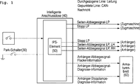
Mit Bezug auf
Die SJB
Die SJB
Das IPS-Element
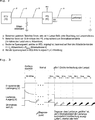
Mit Bezug auf
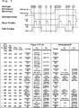
Die Strommenge-Erkennungsschaltung berechnet die Laststrommenge, welche in der Lastlampe fließt, durch das Berücksichtigen der Stromtoleranz der Lastlampe bei einem Punkt A, berechnet eine Strommenge, welche in der Eingangsseite des IPS-Elementes
Die ECU
Entsprechend erkennt die ECU
In dem Verfahren des Erkennens des Anhängers, entsprechend der vorliegenden Offenbarung, erkennt die ECU
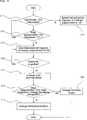
Die ECU
Wenn die ECU
Wenn der Stopplampenschalter in dem Ein-Zustand ist, und die Stopplampe im Schritt S20 in dem Ein-Zustand ist, gibt die ECU
Die ECU
Wenn die Stopplampe im Schritt S40 in dem Aus-Zustand ist, bestimmt die ECU
Die ECU
Wenn der Stoppschalter des Anhängers in dem Ein-Zustand ist und beide, sowohl die Stopplampe als auch die Abbiegesignallampe, in dem „offenen” Zustand im Schritt S60 sind, bestimmt die ECU
Wenn der Stoppschalter des Anhängers in dem Ein-Zustand ist, und entweder die Stopplampe oder die Abbiegesignallampe nicht in dem „offenen” Zustand im Schritt S60 ist, bestimmt die ECU
Wenn der Parkschalter in dem Ein-Zustand ist und der Getriebegangzustand der Parkzustand im Schritt S10 ist, behält die ECU
Ferner, wenn die Stopplampe nicht in dem offenen Zustand im Schritt S40 ist, wiederholt die ECU
Claims (13)
Applications Claiming Priority (2)
| Application Number | Priority Date | Filing Date | Title |
|---|---|---|---|
| KR1020130169383A KR101596699B1 (en) | 2013-12-31 | 2013-12-31 | Method for awaring a trailer use for a tractor |
| KR10-2013-169383 | 2013-12-31 |
Publications (2)
| Publication Number | Publication Date |
|---|---|
| DE102014221235A1 true DE102014221235A1 (en) | 2015-07-02 |
| DE102014221235B4 DE102014221235B4 (en) | 2019-05-09 |
Family
ID=53372286
Family Applications (1)
| Application Number | Title | Priority Date | Filing Date |
|---|---|---|---|
| DE102014221235.9A Expired - Fee Related DE102014221235B4 (en) | 2013-12-31 | 2014-10-20 | Method for detecting a trailer of a tractor vehicle |
Country Status (4)
| Country | Link |
|---|---|
| US (1) | US9403412B2 (en) |
| KR (1) | KR101596699B1 (en) |
| CN (1) | CN104742822B (en) |
| DE (1) | DE102014221235B4 (en) |
Cited By (1)
| Publication number | Priority date | Publication date | Assignee | Title |
|---|---|---|---|---|
| CN109017568A (en) * | 2018-08-09 | 2018-12-18 | 东风商用车有限公司 | Automatic tractor and trailer identification system and control method thereof |
Families Citing this family (22)
| Publication number | Priority date | Publication date | Assignee | Title |
|---|---|---|---|---|
| GB2530995B (en) * | 2014-10-06 | 2018-10-03 | Jaguar Land Rover Ltd | System for detection of trailer attachment dependent on vehicle pitch |
| KR101673786B1 (en) * | 2015-07-02 | 2016-11-07 | 현대자동차주식회사 | System and method for connecting external device with vehicle |
| KR101768144B1 (en) | 2016-01-19 | 2017-08-30 | 현대자동차주식회사 | Automatic Detectable System related to Load Capacity Change and Operation Method Thereof |
| CN106004645B (en) * | 2016-07-07 | 2018-03-20 | 安徽江淮汽车集团股份有限公司 | A kind of trailer turns to lamp control system and control method |
| US10207642B2 (en) * | 2017-03-14 | 2019-02-19 | Phillips Connect Technologies Llc | Electrical power monitoring system |
| EP3379222B1 (en) | 2017-03-22 | 2020-12-30 | Methode Electronics Malta Ltd. | Magnetoelastic based sensor assembly |
| FR3065398B1 (en) * | 2017-04-25 | 2020-09-18 | Peugeot Citroen Automobiles Sa | ON-BOARD AUTOMOTIVE VEHICLE SYSTEM INTENDED TO SUPPLY AND CONTROL LIGHTS FROM A CONNECTED TRAILER |
| US11135882B2 (en) | 2018-02-27 | 2021-10-05 | Methode Electronics, Inc. | Towing systems and methods using magnetic field sensing |
| US11084342B2 (en) | 2018-02-27 | 2021-08-10 | Methode Electronics, Inc. | Towing systems and methods using magnetic field sensing |
| US11221262B2 (en) | 2018-02-27 | 2022-01-11 | Methode Electronics, Inc. | Towing systems and methods using magnetic field sensing |
| EP3758959B1 (en) | 2018-02-27 | 2025-11-05 | Methode Electronics, Inc. | Towing systems and methods using magnetic field sensing |
| US11491832B2 (en) | 2018-02-27 | 2022-11-08 | Methode Electronics, Inc. | Towing systems and methods using magnetic field sensing |
| US11014417B2 (en) | 2018-02-27 | 2021-05-25 | Methode Electronics, Inc. | Towing systems and methods using magnetic field sensing |
| US11562649B2 (en) * | 2018-07-12 | 2023-01-24 | Dish Ukraine L.L.C. | Vehicle to vehicle event notification system and method |
| KR102676236B1 (en) * | 2018-07-27 | 2024-06-19 | 현대자동차주식회사 | System and method for Single channel based multi-function LED lamp drive |
| CN110108957B (en) * | 2019-05-07 | 2020-06-02 | 武汉理工大学 | Tractor electrical fault diagnosis method based on structural analysis method |
| CN110696750B (en) * | 2019-10-30 | 2021-04-27 | 一汽解放汽车有限公司 | Trailer connection state judgment method, device, vehicle and storage medium |
| US11878559B2 (en) * | 2021-03-05 | 2024-01-23 | Ford Global Technologies, Llc | Systems and methods for determining trailer connection |
| CN114084084B (en) * | 2021-11-17 | 2023-12-26 | 一汽解放汽车有限公司 | Trailer connection status judgment method, device computer equipment and storage medium |
| US11933830B2 (en) * | 2022-01-12 | 2024-03-19 | GM Global Technology Operations LLC | Trailer light testing system |
| US20240010125A1 (en) * | 2022-07-05 | 2024-01-11 | Segi R&D Limited | Apparatus, method, and computer-readable storage medium for determining connection of trailer |
| CN116101201A (en) * | 2023-02-25 | 2023-05-12 | 江铃汽车股份有限公司 | Vehicle trailer control method and system |
Family Cites Families (20)
| Publication number | Priority date | Publication date | Assignee | Title |
|---|---|---|---|---|
| US4614356A (en) * | 1985-09-23 | 1986-09-30 | Roy Mills | Apparatus for aligning hitches of towing and towed vehicles |
| JPH07257345A (en) * | 1994-03-28 | 1995-10-09 | Jidosha Kiki Co Ltd | Detecting device of antiskid brake control device for trailer |
| AU719780B2 (en) * | 1998-09-10 | 2000-05-18 | Dennis Ronald Gravolin | Electrical tell tale system for trailers |
| JP4038898B2 (en) * | 1998-10-21 | 2008-01-30 | アンデン株式会社 | Direction indicator for vehicle towing trailer and trailer connection determination circuit used for direction indicator |
| DE102004029129B4 (en) * | 2004-06-17 | 2008-08-28 | Daimler Ag | Method and device for coupling a trailer to a motor vehicle |
| US7463139B2 (en) * | 2004-10-18 | 2008-12-09 | Stmicroelectronics, Inc. | Method and system for driving a vehicle trailer tow connector |
| US7619506B2 (en) | 2005-08-25 | 2009-11-17 | Qualcomm Incorporated | Device for sensing tractor trailer connection |
| US9014871B2 (en) * | 2006-03-22 | 2015-04-21 | Eaton Corporation | Method and system for associating a vehicle trailer to a vehicle |
| US7535346B2 (en) * | 2006-04-17 | 2009-05-19 | Master Lock Company Llc | Trailer alarm |
| US8031061B2 (en) * | 2006-04-17 | 2011-10-04 | Master Lock Company Llc | Trailer alarm |
| DE102006029367A1 (en) * | 2006-06-27 | 2008-01-03 | Robert Bosch Gmbh | Method and control unit for detecting trailer operation in a towing vehicle |
| US8068019B2 (en) * | 2008-12-23 | 2011-11-29 | Ford Global Technologies | Trailer identification system |
| US20100271189A1 (en) * | 2009-04-22 | 2010-10-28 | Thomas Lee Miller | Method for configuring and monitoring a trailer in tow using an integrated trailer brake controller |
| US9174503B2 (en) * | 2010-03-18 | 2015-11-03 | Grote Industries, Inc. | Environment activated automatic shut-off switch system and method |
| DE102010018127A1 (en) * | 2010-04-24 | 2011-10-27 | Wabco Gmbh | Connecting device for a trailer vehicle and trailer vehicle with connection device |
| US8665078B2 (en) * | 2011-07-25 | 2014-03-04 | Ford Global Technologies | Width calibration of lane departure warning system |
| US8890670B2 (en) * | 2011-08-09 | 2014-11-18 | Continental Automotive Systems, Inc. | Smart trailer |
| US8845155B2 (en) * | 2012-06-18 | 2014-09-30 | Cequent Consumer Products, Inc. | Trailer adapter with light |
| US9199521B2 (en) * | 2013-02-19 | 2015-12-01 | Ford Global Technologies, Llc | Trailer theft detection and alarm |
| DE102013103307A1 (en) * | 2013-04-03 | 2014-10-23 | Hella Kgaa Hueck & Co. | Device and method for monitoring a trailer connection box |
-
2013
- 2013-12-31 KR KR1020130169383A patent/KR101596699B1/en active Active
-
2014
- 2014-10-20 DE DE102014221235.9A patent/DE102014221235B4/en not_active Expired - Fee Related
- 2014-11-03 US US14/531,954 patent/US9403412B2/en active Active
- 2014-12-16 CN CN201410784480.5A patent/CN104742822B/en active Active
Cited By (2)
| Publication number | Priority date | Publication date | Assignee | Title |
|---|---|---|---|---|
| CN109017568A (en) * | 2018-08-09 | 2018-12-18 | 东风商用车有限公司 | Automatic tractor and trailer identification system and control method thereof |
| CN109017568B (en) * | 2018-08-09 | 2023-05-30 | 东风商用车有限公司 | Automatic recognition tractor trailer system and control method thereof |
Also Published As
| Publication number | Publication date |
|---|---|
| DE102014221235B4 (en) | 2019-05-09 |
| KR20150080339A (en) | 2015-07-09 |
| US9403412B2 (en) | 2016-08-02 |
| US20150183284A1 (en) | 2015-07-02 |
| CN104742822A (en) | 2015-07-01 |
| KR101596699B1 (en) | 2016-02-24 |
| CN104742822B (en) | 2018-10-30 |
Similar Documents
| Publication | Publication Date | Title |
|---|---|---|
| DE102014221235B4 (en) | Method for detecting a trailer of a tractor vehicle | |
| DE102016206663A1 (en) | Error determination system for a button-type switching device | |
| DE102005018363A1 (en) | Control circuit for a start-up relay with its own fault diagnosis function | |
| DE112016001241B4 (en) | VEHICLE CONTROL DEVICE AND METHOD FOR CONTROLLING A VEHICLE CONTROL DEVICE | |
| DE102012203301B4 (en) | load driver device | |
| DE112017005122T5 (en) | Vehicle-side control | |
| DE102014012439A1 (en) | A method and apparatus for restoring a normal condition of a mechanical relay from a sticking fault condition | |
| DE202016103923U1 (en) | Bicycle control and bicycle control system having the bicycle control | |
| DE112016006414T5 (en) | Anormity monitoring device and electric power steering device using the same | |
| DE102014220646A1 (en) | Use of a bus line for transmitting alternative signal codes | |
| DE102008009652A1 (en) | Monitoring device and monitoring method for a sensor, and sensor | |
| DE202014100980U1 (en) | Drive system with a DC motor brake | |
| WO2012048970A1 (en) | Device and method for signaling malfunctions of a vehicle | |
| WO2012130511A2 (en) | Method and device for operating a generator | |
| DE102017127453A1 (en) | Control and method for devices and systems of motor vehicles | |
| EP0417422A2 (en) | Process and device for controlling the brake lights of a vehicle | |
| DE102008035920A1 (en) | Circuit arrangement for a serial communication with wake-up function | |
| DE102014011798A1 (en) | A method of reducing a current drawn from a high-voltage battery of a motor vehicle and a high-voltage system suitable for the method | |
| DE112019004153B4 (en) | ELECTRONIC CONTROL UNIT | |
| DE102020214565A1 (en) | Method for detecting faulty electrical contacts in a battery-powered vehicle and electrical system | |
| WO2016041716A1 (en) | Monitoring the functioning of a door contact of a vehicle door | |
| DE102013021640A1 (en) | Method and device for determining the power potential of a battery | |
| EP4449135B1 (en) | Supply circuit having a computer device for diagnosing a connecting circuit, in particular for power electronics in a vehicle, and method for operating a supply circuit having a computer device for diagnosing a connecting circuit | |
| EP2469985B1 (en) | Device and method for ensuring LED lights are correctly evaluated in combination with on-board vehicle computers | |
| DE102017002849A1 (en) | Status detection management in a vehicle |
Legal Events
| Date | Code | Title | Description |
|---|---|---|---|
| R012 | Request for examination validly filed | ||
| R016 | Response to examination communication | ||
| R018 | Grant decision by examination section/examining division | ||
| R020 | Patent grant now final | ||
| R119 | Application deemed withdrawn, or ip right lapsed, due to non-payment of renewal fee |