DE102014220017A1 - Battery system with a trained for supplying a high-voltage network with electrical energy battery and a measuring device for measuring at least one insulation resistance of the battery - Google Patents

Battery system with a trained for supplying a high-voltage network with electrical energy battery and a measuring device for measuring at least one insulation resistance of the battery Download PDF

Info

Publication number
DE102014220017A1
DE102014220017A1 DE102014220017.2A DE102014220017A DE102014220017A1 DE 102014220017 A1 DE102014220017 A1 DE 102014220017A1 DE 102014220017 A DE102014220017 A DE 102014220017A DE 102014220017 A1 DE102014220017 A1 DE 102014220017A1
Authority
DE
Germany
Prior art keywords
voltage
battery
measuring
housing
measuring device
Prior art date
Legal status (The legal status is an assumption and is not a legal conclusion. Google has not performed a legal analysis and makes no representation as to the accuracy of the status listed.)
Pending
Application number
DE102014220017.2A
Other languages
German (de)
Inventor
Thomas Schaedlich
Chrysanthos Tzivanopoulos
Current Assignee (The listed assignees may be inaccurate. Google has not performed a legal analysis and makes no representation or warranty as to the accuracy of the list.)
Robert Bosch GmbH
Original Assignee
Robert Bosch GmbH
Priority date (The priority date is an assumption and is not a legal conclusion. Google has not performed a legal analysis and makes no representation as to the accuracy of the date listed.)
Filing date
Publication date
Application filed by Robert Bosch GmbH filed Critical Robert Bosch GmbH
Priority to DE102014220017.2A priority Critical patent/DE102014220017A1/en
Priority to KR1020177008743A priority patent/KR20170065520A/en
Priority to JP2017517664A priority patent/JP6485825B2/en
Priority to PCT/EP2015/068635 priority patent/WO2016050406A1/en
Priority to US15/516,066 priority patent/US9931957B2/en
Priority to CN201580053717.5A priority patent/CN107005065B/en
Publication of DE102014220017A1 publication Critical patent/DE102014220017A1/en
Pending legal-status Critical Current

Links

Images

Classifications

    • BPERFORMING OPERATIONS; TRANSPORTING
    • B60VEHICLES IN GENERAL
    • B60LPROPULSION OF ELECTRICALLY-PROPELLED VEHICLES; SUPPLYING ELECTRIC POWER FOR AUXILIARY EQUIPMENT OF ELECTRICALLY-PROPELLED VEHICLES; ELECTRODYNAMIC BRAKE SYSTEMS FOR VEHICLES IN GENERAL; MAGNETIC SUSPENSION OR LEVITATION FOR VEHICLES; MONITORING OPERATING VARIABLES OF ELECTRICALLY-PROPELLED VEHICLES; ELECTRIC SAFETY DEVICES FOR ELECTRICALLY-PROPELLED VEHICLES
    • B60L3/00Electric devices on electrically-propelled vehicles for safety purposes; Monitoring operating variables, e.g. speed, deceleration or energy consumption
    • B60L3/0023Detecting, eliminating, remedying or compensating for drive train abnormalities, e.g. failures within the drive train
    • B60L3/0069Detecting, eliminating, remedying or compensating for drive train abnormalities, e.g. failures within the drive train relating to the isolation, e.g. ground fault or leak current
    • GPHYSICS
    • G01MEASURING; TESTING
    • G01RMEASURING ELECTRIC VARIABLES; MEASURING MAGNETIC VARIABLES
    • G01R27/00Arrangements for measuring resistance, reactance, impedance, or electric characteristics derived therefrom
    • G01R27/02Measuring real or complex resistance, reactance, impedance, or other two-pole characteristics derived therefrom, e.g. time constant
    • G01R27/16Measuring impedance of element or network through which a current is passing from another source, e.g. cable, power line
    • G01R27/18Measuring resistance to earth, i.e. line to ground
    • BPERFORMING OPERATIONS; TRANSPORTING
    • B60VEHICLES IN GENERAL
    • B60LPROPULSION OF ELECTRICALLY-PROPELLED VEHICLES; SUPPLYING ELECTRIC POWER FOR AUXILIARY EQUIPMENT OF ELECTRICALLY-PROPELLED VEHICLES; ELECTRODYNAMIC BRAKE SYSTEMS FOR VEHICLES IN GENERAL; MAGNETIC SUSPENSION OR LEVITATION FOR VEHICLES; MONITORING OPERATING VARIABLES OF ELECTRICALLY-PROPELLED VEHICLES; ELECTRIC SAFETY DEVICES FOR ELECTRICALLY-PROPELLED VEHICLES
    • B60L3/00Electric devices on electrically-propelled vehicles for safety purposes; Monitoring operating variables, e.g. speed, deceleration or energy consumption
    • B60L3/12Recording operating variables ; Monitoring of operating variables
    • BPERFORMING OPERATIONS; TRANSPORTING
    • B60VEHICLES IN GENERAL
    • B60LPROPULSION OF ELECTRICALLY-PROPELLED VEHICLES; SUPPLYING ELECTRIC POWER FOR AUXILIARY EQUIPMENT OF ELECTRICALLY-PROPELLED VEHICLES; ELECTRODYNAMIC BRAKE SYSTEMS FOR VEHICLES IN GENERAL; MAGNETIC SUSPENSION OR LEVITATION FOR VEHICLES; MONITORING OPERATING VARIABLES OF ELECTRICALLY-PROPELLED VEHICLES; ELECTRIC SAFETY DEVICES FOR ELECTRICALLY-PROPELLED VEHICLES
    • B60L58/00Methods or circuit arrangements for monitoring or controlling batteries or fuel cells, specially adapted for electric vehicles
    • B60L58/10Methods or circuit arrangements for monitoring or controlling batteries or fuel cells, specially adapted for electric vehicles for monitoring or controlling batteries
    • GPHYSICS
    • G01MEASURING; TESTING
    • G01RMEASURING ELECTRIC VARIABLES; MEASURING MAGNETIC VARIABLES
    • G01R27/00Arrangements for measuring resistance, reactance, impedance, or electric characteristics derived therefrom
    • G01R27/02Measuring real or complex resistance, reactance, impedance, or other two-pole characteristics derived therefrom, e.g. time constant
    • G01R27/025Measuring very high resistances, e.g. isolation resistances, i.e. megohm-meters
    • GPHYSICS
    • G01MEASURING; TESTING
    • G01RMEASURING ELECTRIC VARIABLES; MEASURING MAGNETIC VARIABLES
    • G01R27/00Arrangements for measuring resistance, reactance, impedance, or electric characteristics derived therefrom
    • G01R27/02Measuring real or complex resistance, reactance, impedance, or other two-pole characteristics derived therefrom, e.g. time constant
    • G01R27/16Measuring impedance of element or network through which a current is passing from another source, e.g. cable, power line
    • GPHYSICS
    • G01MEASURING; TESTING
    • G01RMEASURING ELECTRIC VARIABLES; MEASURING MAGNETIC VARIABLES
    • G01R31/00Arrangements for testing electric properties; Arrangements for locating electric faults; Arrangements for electrical testing characterised by what is being tested not provided for elsewhere
    • G01R31/12Testing dielectric strength or breakdown voltage ; Testing or monitoring effectiveness or level of insulation, e.g. of a cable or of an apparatus, for example using partial discharge measurements; Electrostatic testing
    • G01R31/1227Testing dielectric strength or breakdown voltage ; Testing or monitoring effectiveness or level of insulation, e.g. of a cable or of an apparatus, for example using partial discharge measurements; Electrostatic testing of components, parts or materials
    • GPHYSICS
    • G01MEASURING; TESTING
    • G01RMEASURING ELECTRIC VARIABLES; MEASURING MAGNETIC VARIABLES
    • G01R31/00Arrangements for testing electric properties; Arrangements for locating electric faults; Arrangements for electrical testing characterised by what is being tested not provided for elsewhere
    • G01R31/36Arrangements for testing, measuring or monitoring the electrical condition of accumulators or electric batteries, e.g. capacity or state of charge [SoC]
    • G01R31/382Arrangements for monitoring battery or accumulator variables, e.g. SoC
    • HELECTRICITY
    • H01ELECTRIC ELEMENTS
    • H01MPROCESSES OR MEANS, e.g. BATTERIES, FOR THE DIRECT CONVERSION OF CHEMICAL ENERGY INTO ELECTRICAL ENERGY
    • H01M10/00Secondary cells; Manufacture thereof
    • H01M10/42Methods or arrangements for servicing or maintenance of secondary cells or secondary half-cells
    • H01M10/425Structural combination with electronic components, e.g. electronic circuits integrated to the outside of the casing
    • HELECTRICITY
    • H01ELECTRIC ELEMENTS
    • H01MPROCESSES OR MEANS, e.g. BATTERIES, FOR THE DIRECT CONVERSION OF CHEMICAL ENERGY INTO ELECTRICAL ENERGY
    • H01M10/00Secondary cells; Manufacture thereof
    • H01M10/42Methods or arrangements for servicing or maintenance of secondary cells or secondary half-cells
    • H01M10/48Accumulators combined with arrangements for measuring, testing or indicating the condition of cells, e.g. the level or density of the electrolyte
    • HELECTRICITY
    • H02GENERATION; CONVERSION OR DISTRIBUTION OF ELECTRIC POWER
    • H02JELECTRIC POWER NETWORKS; CIRCUIT ARRANGEMENTS OR SYSTEMS FOR SUPPLYING OR DISTRIBUTING ELECTRIC POWER; SYSTEMS FOR STORING ELECTRIC ENERGY
    • H02J7/00Circuit arrangements for charging or discharging batteries or for supplying loads from batteries
    • HELECTRICITY
    • H01ELECTRIC ELEMENTS
    • H01MPROCESSES OR MEANS, e.g. BATTERIES, FOR THE DIRECT CONVERSION OF CHEMICAL ENERGY INTO ELECTRICAL ENERGY
    • H01M2200/00Safety devices for primary or secondary batteries
    • YGENERAL TAGGING OF NEW TECHNOLOGICAL DEVELOPMENTS; GENERAL TAGGING OF CROSS-SECTIONAL TECHNOLOGIES SPANNING OVER SEVERAL SECTIONS OF THE IPC; TECHNICAL SUBJECTS COVERED BY FORMER USPC CROSS-REFERENCE ART COLLECTIONS [XRACs] AND DIGESTS
    • Y02TECHNOLOGIES OR APPLICATIONS FOR MITIGATION OR ADAPTATION AGAINST CLIMATE CHANGE
    • Y02EREDUCTION OF GREENHOUSE GAS [GHG] EMISSIONS, RELATED TO ENERGY GENERATION, TRANSMISSION OR DISTRIBUTION
    • Y02E60/00Enabling technologies; Technologies with a potential or indirect contribution to GHG emissions mitigation
    • Y02E60/10Energy storage using batteries
    • YGENERAL TAGGING OF NEW TECHNOLOGICAL DEVELOPMENTS; GENERAL TAGGING OF CROSS-SECTIONAL TECHNOLOGIES SPANNING OVER SEVERAL SECTIONS OF THE IPC; TECHNICAL SUBJECTS COVERED BY FORMER USPC CROSS-REFERENCE ART COLLECTIONS [XRACs] AND DIGESTS
    • Y02TECHNOLOGIES OR APPLICATIONS FOR MITIGATION OR ADAPTATION AGAINST CLIMATE CHANGE
    • Y02TCLIMATE CHANGE MITIGATION TECHNOLOGIES RELATED TO TRANSPORTATION
    • Y02T10/00Road transport of goods or passengers
    • Y02T10/60Other road transportation technologies with climate change mitigation effect
    • Y02T10/70Energy storage systems for electromobility, e.g. batteries

Landscapes

  • Engineering & Computer Science (AREA)
  • Power Engineering (AREA)
  • General Physics & Mathematics (AREA)
  • Physics & Mathematics (AREA)
  • Sustainable Energy (AREA)
  • Mechanical Engineering (AREA)
  • Transportation (AREA)
  • Sustainable Development (AREA)
  • Life Sciences & Earth Sciences (AREA)
  • Manufacturing & Machinery (AREA)
  • Chemical & Material Sciences (AREA)
  • Chemical Kinetics & Catalysis (AREA)
  • General Chemical & Material Sciences (AREA)
  • Electrochemistry (AREA)
  • Microelectronics & Electronic Packaging (AREA)
  • Secondary Cells (AREA)
  • Testing Of Short-Circuits, Discontinuities, Leakage, Or Incorrect Line Connections (AREA)
  • Charge And Discharge Circuits For Batteries Or The Like (AREA)

Abstract

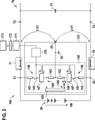
Die vorliegende Erfindung betrifft ein Batteriesystem (100) mit einer zum Versorgen eines Hochvoltnetzes (70) mit elektrischer Energie ausgebildeten Batterie (20) und einer Messeinrichtung (130) zum Messen mindestens eines zwischen der Batterie (20) und einem Gehäuse der Batterie (20) vorhandenen Isolationswiderstandes. Dabei sind in der Messeinrichtung (130) zwei jeweils einem Hochvoltanschluss (21, 22) von zwei Hochvoltanschlüssen (21, 22) der Batterie (20) zugeordnete Messpfade (140, 150) angeordnet, die jeweils eine Reihenschaltung, die einen ersten Widerstand (142, 152) und ein Relais (145, 155) umfasst, aufweisen und jeweils zwischen dem zugeordneten Hochvoltanschluss (21, 22) und einem ein Gehäusepotential aufweisenden Punkt (25) angeschlossen sind. Ferner umfasst jede Reihenschaltung einen Halbleiterschalter (147, 157). Auch weist die Messeinrichtung (130) zwei Funktionsmodi auf, in denen die Relais (145, 155) der Messpfade (140, 150) geschlossen sind. Dabei ist die in einen passiven Funktionsmodus der zwei Funktionsmodi geschaltete Messeinrichtung (130) dazu ausgebildet, die Halbeiterschalter (147, 157) jeweils zu öffnen oder in einem geöffneten Zustand zu halten. Weiterhin ist die in einen aktiven Funktionsmodus der zwei Funktionsmodi geschaltete Messeinrichtung (130) dazu ausgebildet, die Halbleiterschalter (147, 157) abwechselnd zu schließen und zu öffnen, bei geschlossenem Halbleiterschalter (147, 157) jedes Messpfades (140, 150) eine über den ersten Widerstand (142, 152) des entsprechenden Messpfades (140, 150) abfallende erste Spannung jeweils zu messen und anhand jeder gemessenen ersten Spannung einen entsprechenden Isolationswiderstand der Batterie (20) zu bestimmen.The present invention relates to a battery system (100) having a battery (20) designed to supply a high-voltage network (70) with electrical energy and a measuring device (130) for measuring at least one between the battery (20) and a housing of the battery (20). existing insulation resistance. In this case, two measuring paths (140, 150) each assigned to a high-voltage terminal (21, 22) of two high-voltage terminals (21, 22) of the battery (20) are arranged in the measuring device (130), each of which has a series circuit comprising a first resistor (142 , 152) and a relay (145, 155) comprises, and in each case between the associated high-voltage terminal (21, 22) and a housing having a potential point (25) are connected. Furthermore, each series circuit comprises a semiconductor switch (147, 157). Also, the measuring device (130) has two functional modes in which the relays (145, 155) of the measuring paths (140, 150) are closed. In this case, the measuring device (130) connected in a passive functional mode of the two functional modes is designed to open the semiconductor switches (147, 157) in each case or to keep them in an opened state. Furthermore, the measuring device (130) connected in an active functional mode of the two functional modes is designed to alternately close and open the semiconductor switches (147, 157) via the semiconductor switch (147, 157) of each measuring path (140, 150) first resistance (142, 152) of the corresponding measuring path (140, 150) dropping first voltage to be measured in each case and to determine a corresponding insulation resistance of the battery (20) on the basis of each measured first voltage.

Description

Die vorliegende Erfindung betrifft ein Batteriesystem mit einer zum Versorgen eines Hochvoltnetzes mit elektrischer Energie ausgebildeten Batterie und einer Messeinrichtung zum Messen mindestens eines Isolationswiderstandes der Batterie und ein entsprechendes Verfahren zum Messen mindestens eines Isolationswiderstandes einer zum Versorgen eines Hochvoltnetzes mit elektrischer Energie ausgebildeten Batterie. Auch betrifft die Erfindung ein Fahrzeug mit einem solchen Batteriesystem.The present invention relates to a battery system with a trained for supplying a high-voltage network with electrical energy battery and a measuring device for measuring at least one insulation resistance of the battery and a corresponding method for measuring at least one insulation resistance of a trained for supplying a high-voltage network with electrical energy battery. The invention also relates to a vehicle with such a battery system.

Stand der TechnikState of the art

1 zeigt ein aus dem Stand der Technik bekanntes Batteriesystem 10 mit einer als Hochvoltbatterie beziehungsweise Traktionsbatterie ausgebildeten Batterie 20 und einer Messeinrichtung 30 zum Messen mindestens eines Isolationswiderstandes der Batterie 20, der innerhalb oder außerhalb der Batterie 20 vorhandenen ist. Die Batterie 20 umfasst mehrere in Reihe geschaltete Batteriezellen. Zur Vereinfachung der Darstellung sind die mehreren Batteriezellen nicht mit Bezugszeichen versehen. Dabei ist ein erster Isolationswiderstand 26 derjenige Isolationswiderstand der Batterie 20, der zwischen einem positiven Hochvoltanschluss 21 der Batterie 20 und einem ein Potential eines Gehäuses der Batterie 20 aufweisenden Punkt 25, der im Folgenden als Gehäusemasse 25 bezeichnet wird, vorhanden ist. Ferner ist ein zweiter Isolationswiderstand 27 derjenige Isolationswiderstand der Batterie 20, der zwischen einem negativen Hochvoltanschluss 22 der Batterie 20 und der Gehäusemasse 25 vorhanden ist. Der positive Hochvoltanschluss 21 der Batterie 20 wird im Folgenden als erster Hochvoltanschluss 21 der Batterie 20 bezeichnet. Der negative Hochvoltanschluss 22 der Batterie 20 wird im Folgenden als zweiter Hochvoltanschluss 21 der Batterie 20 bezeichnet. Ferner ist ein dritter Isolationswiderstand 28 derjenige Isolationswiderstand der Batterie 20, der zwischen einem Verbindungspunkt, über den mindestens zwei Batteriezellen der Batterie 20 miteinander verbunden sind, und der Gehäusemasse 25 vorhanden ist. 1 shows a known from the prior art battery system 10 with a battery designed as a high-voltage battery or traction battery 20 and a measuring device 30 for measuring at least one insulation resistance of the battery 20 that is inside or outside the battery 20 existing is. The battery 20 includes several series connected battery cells. For ease of illustration, the multiple battery cells are not provided with reference numerals. Here is a first insulation resistance 26 the insulation resistance of the battery 20 that is between a positive high-voltage connection 21 the battery 20 and a potential of a case of the battery 20 having point 25 hereinafter referred to as housing ground 25 is designated exists. Furthermore, a second insulation resistance 27 the insulation resistance of the battery 20 that is between a negative high-voltage connection 22 the battery 20 and the housing ground 25 is available. The positive high-voltage connection 21 the battery 20 is hereinafter referred to as the first high-voltage connection 21 the battery 20 designated. The negative high-voltage connection 22 the battery 20 is hereinafter referred to as a second high-voltage connection 21 the battery 20 designated. Furthermore, a third insulation resistance 28 the insulation resistance of the battery 20 passing between a connection point, over the at least two battery cells of the battery 20 connected to each other, and the housing ground 25 is available.

Die in einem Batteriesteuergerät (nicht dargestellt) des Batteriesystems 10 angeordnete Messeinrichtung 30 umfasst einen ersten Messpfad 40 und einen zweiten Messpfad 50, die jeweils einen hochohmigen resistiven Spannungsteiler 41, 51 und ein Relais 45, 55 umfassen und zwischen einem zugeordneten Hochvoltanschluss 21, 22 der zwei Hochvoltanschlüsse 21, 22 und der Gehäusemasse 25 schaltbar sind. Dabei ist dem ersten Messpfad 40 der erste Hochvoltanschluss 21 zugeordnet. Auch ist dem zweiten Messpfad 50 der zweite Hochvoltanschluss 22 zugeordnet. Jeder Spannungsteiler 41, 51 ist aus einem ersten Widerstand 42, 52 und einem zweiten Widerstand 43, 53 ausgebildet. Dabei ist jeder erste Widerstand 42, 52 mit der Gehäusemasse 25 verbunden und jeder zweite Widerstand 43, 53 ist über das entsprechende Relais 45, 55 mit dem zugeordneten Hochvoltanschluss 21, 22 verbindbar. Liegt ein Isolationsfehler zwischen der Batterie 20 und dem Gehäuse vor, so fließt beim abwechselnden Schließen der Relais 45, 55 der Messpfade 40, 50 durch mindestens einen der Spannungsteiler 41, 51 ein messbarer Stromfluss, wodurch auch eine messbare Spannung über den ersten Widerstand 42, 52 dieses mindestens einen Spannungsteilers 41, 51 abfällt. Jede über den ersten Widerstand 42, 52 jedes Spannungsteilers 41, 51 abfallende Spannung wird über einen dem entsprechenden Messpfad 40, 50 jeweils zugeordneten Messeingang 49, 59 einer Auswerte- und Steuereinheit 60 der Messeinrichtung 30 gemessen. Der dem ersten Messpfad 40 zugeordnete Messeingang 49 ist über einen weiteren Widerstand 46 mit demjenigen Anschluss des ersten Widerstandes 42 des Spannungsteilers 41 des ersten Messpfades 40 verbunden, der nicht mit der Gehäusemasse 25 verbunden ist. Zum Messen der über den ersten Widerstand 52 des Spannungsteilers 51 des zweiten Messpfades 50 abfallenden Spannung ist in der Messeinrichtung 30 ein Operationsverstärker 56 vorhanden, der eingangsseitig mit dem ersten Widerstand 52 des Spannungsteilers 51 des zweiten Messpfades 50 und ausgangsseitig mit dem dem zweiten Messpfad 50 zugeordneten Messeingang 59 der Auswerte- und Steuereinheit 60 verbunden ist. Die Auswerte- und Steuereinheit 60 bestimmt folglich die über die ersten Widerstände 42, 52 der Spannungsteiler 41, 51 jeweils abfallenden Spannungen. Durch abwechselndes Schalten der Messpfade 40, 50, Bestimmen der über jeden ersten Widerstand 42, 52 abfallenden Spannung und unter Berücksichtigung von bekannten Systemgrößen können die Isolationswiderstände 26, 27, 28 der Batterie 20 jeweils berechnet werden. Die Auswerte- und Steuereinheit 60 ist ferner dazu ausgebildet, die Relais 45, 55 zu steuern, das heißt, diese zu öffnen und schließen.The in a battery control unit (not shown) of the battery system 10 arranged measuring device 30 includes a first measurement path 40 and a second measurement path 50 , each a high-impedance resistive voltage divider 41 . 51 and a relay 45 . 55 include and between an associated high-voltage connection 21 . 22 the two high-voltage connections 21 . 22 and the housing ground 25 are switchable. Here is the first measurement path 40 the first high-voltage connection 21 assigned. Also, the second measuring path 50 the second high-voltage connection 22 assigned. Every voltage divider 41 . 51 is from a first resistance 42 . 52 and a second resistor 43 . 53 educated. There is every first resistance 42 . 52 with the housing ground 25 connected and every second resistor 43 . 53 is via the corresponding relay 45 . 55 with the assigned high-voltage connection 21 . 22 connectable. Is an insulation fault between the battery 20 and the housing, the relay will flow when alternately closing 45 . 55 the measuring paths 40 . 50 through at least one of the voltage dividers 41 . 51 a measurable current flow, which also produces a measurable voltage across the first resistor 42 . 52 this at least one voltage divider 41 . 51 drops. Each over the first resistance 42 . 52 each voltage divider 41 . 51 decreasing voltage is via a the corresponding measuring path 40 . 50 respectively assigned measuring input 49 . 59 an evaluation and control unit 60 the measuring device 30 measured. The first measuring path 40 assigned measuring input 49 is about another resistance 46 with that connection of the first resistor 42 of the voltage divider 41 of the first measuring path 40 connected, which does not match the case ground 25 connected is. To measure over the first resistor 52 of the voltage divider 51 of the second measuring path 50 decreasing voltage is in the measuring device 30 an operational amplifier 56 present, the input side with the first resistor 52 of the voltage divider 51 of the second measuring path 50 and on the output side with the second measuring path 50 assigned measuring input 59 the evaluation and control unit 60 connected is. The evaluation and control unit 60 thus determines the over the first resistances 42 . 52 the voltage divider 41 . 51 each falling voltage. By alternately switching the measuring paths 40 . 50 Determine the over each first resistor 42 . 52 decreasing voltage and taking into account known system sizes, the insulation resistance 26 . 27 . 28 the battery 20 each calculated. The evaluation and control unit 60 is further adapted to the relay 45 . 55 to control, that is, to open and close them.

Die in der 1 dargestellte Batterie 20 ist zum Versorgen eines Hochvoltnetzes 70 mit elektrischer Energie ausgebildet. Dazu ist die Batterie 20 über zwei weitere Relais 71, 72 an das Hochvoltnetz 70 anschließbar. Über die zwei weiteren Relais 71, 72 sind der erste Hochvoltanschluss 21 der Batterie 20 mit einem ersten Hochvoltnetzanschluss 73 des Hochvoltnetzes 70 und der zweite Hochvoltanschluss 22 der Batterie 20 mit einem zweiten Hochvoltnetzanschluss 74 des Hochvoltnetzes 70 direkt verbindbar. Zwischen den zwei Hochvoltnetzanschlüssen 73, 74 des Hochvoltnetzes 70 ist eine Reihenschaltung von zwei Kondensatoren 75, 76 (Y-Kondensatoren) vorhanden, die parallel zu einem Zwischenkreiskondensator 77 geschaltet ist, der einen Zwischenkreis bildet. Ein Verbindungspunkt, über den die zwei in Reihe geschalteten Kondensatoren 75, 76 verbunden sind, ist mit einer Gehäusemasse 25 verbunden. Das Hochvoltnetz 70 umfasst ferner einen Inverter 78 und einen Motor 79. Der Inverter 78 ist eingangsseitig parallel zu dem Zwischenkreiskondensator 77 geschaltet und dazu ausgebildet, eine von der Batterie 20 bereitstellbare Gleichspannung in eine dreiphasige Wechselspannung umzuwandeln und diese ausgangsseitig dem Motor 79 bereitzustellen.The in the 1 illustrated battery 20 is to power a high voltage network 70 formed with electrical energy. This is the battery 20 over two more relays 71 . 72 to the high-voltage network 70 connected. About the two other relays 71 . 72 are the first high-voltage connection 21 the battery 20 with a first high-voltage power supply 73 the high-voltage network 70 and the second high-voltage connection 22 the battery 20 with a second high-voltage power supply 74 the high-voltage network 70 directly connectable. Between the two high voltage mains connections 73 . 74 the high-voltage network 70 is a series connection of two capacitors 75 . 76 (Y capacitors) present, which are parallel to a DC link capacitor 77 is connected, which forms a DC link. A connection point over which the two capacitors connected in series 75 . 76 are connected to a housing ground 25 connected. The High-voltage network 70 further includes an inverter 78 and a motor 79 , The inverter 78 is input side parallel to the DC link capacitor 77 switched and trained, one from the battery 20 convertable DC voltage into a three-phase AC voltage and this output side of the engine 79 provide.

Gemäß dem Stand der Technik muss eine Spannungsfestigkeit zwischen einem von dem Hochvoltnetz 70 galvanisch getrennten Niedervoltnetz und der Batterie 20 beziehungsweise zwischen der Gehäusemasse 25 und der Batterie 20 im Produktionswerk sowie bei allen Reparaturen der Batterie 20 messtechnisch nachgewiesen werden. Hierzu wird während eines Spannungsfestigkeitstestes (Spannungsfestigkeitsprüfung) mittels des in einen Testmodus geschalteten Batteriesteuergerätes (nicht dargestellt) eine Testspannung zwischen der Gehäusemasse 25 und jedem Hochvoltanschluss 21, 22 der Batterie 20 für eine definierte Zeit angelegt. Das hier zu verwendende Prüfkriterium ist ein gemessener Stromwert. Dabei wird die Testspannung in Form einer Gleichspannung oder einer Wechselspannung bereitgestellt.According to the prior art, a dielectric strength between one of the high-voltage network 70 galvanically isolated low-voltage network and the battery 20 or between the housing ground 25 and the battery 20 in the production plant as well as with all repairs of the battery 20 be detected metrologically. For this purpose, during a voltage strength test (dielectric strength test) by means of the battery control device (not shown) connected in a test mode, a test voltage is applied between the housing ground 25 and every high-voltage connection 21 . 22 the battery 20 created for a defined time. The test criterion to be used here is a measured current value. In this case, the test voltage is provided in the form of a DC voltage or an AC voltage.

Um eine Messelektronik der Messeinrichtung 30 vor Schädigung durch den Spannungsfestigkeitstest zu schützen sowie ein Überschreiten eines vordefinierten Stromgrenzwertes durch den Stromwert eines jeden bei einer Isolationswiderstandsmessung auftretenden Messstroms zu vermeiden, müssen die Messpfade 40, 50 entsprechend hochohmig aufgebaut sein. Da der vordefinierte Stromgrenzwert nicht unendlich klein gewählt werden kann, wird jeder Messpfad 40, 50 in einer Zeit, in der der Spannungsfestigkeitstest stattfindet, und in einer Zeit, in der keine Isolationswiderstandsmessung stattfindet, galvanisch von der Batterie 20 und folglich auch vom Hochvoltspannungsnetz 70 getrennt, indem die Relais 45, 55 (elektromechanische Schalter) geöffnet werden.To a measuring electronics of the measuring device 30 To protect against damage by the dielectric strength test and to avoid exceeding a predefined current limit by the current value of each occurring during an insulation resistance measurement current, the measuring paths 40 . 50 be constructed correspondingly high impedance. Since the predefined current limit value can not be selected infinitely small, each measuring path becomes 40 . 50 in a time when the withstand voltage test takes place, and in a time when no insulation resistance measurement is taking place, galvanically from the battery 20 and consequently also from the high-voltage network 70 disconnected by the relays 45 . 55 (electromechanical switches) are opened.

Gemäß dem Stand der Technik wird die Messeinrichtung 30 bei jeder Isolationswiderstandsmessung über das Relais 45 des ersten Messpfades 40 oder über das Relais 55 des zweiten Messpfades 50 mit der Batterie 20 verbunden. Jedes Relais 45, 55 erfährt während seiner Lebensdauer mehrere zehn- bis hunderttausend Schaltvorgänge beziehungsweise Schaltspiele. Die niedrigen Messströme, die bei den Isolationswiderstandsmessungen auftreten und die hohen Schaltspannungen, die Spannungswerte von mehreren hundert Volt aufweisen, begünstigen eine energiearme Glimmentladung während der Schaltvorgänge dieser Relais 45, 55. In Kombination mit einem potentiell ausgasenden Material von Relaisgehäusen kann dies zu einer unerwünschten Karbonisierung beziehungsweise Schichtbildung auf den Schaltkontakten der Relais 45, 55 führen. Ein stromabhängiger Schaltkontakt-Übergangswiderstand der Relais 45, 55 kann entstehen und die Messung verfälschen.According to the prior art, the measuring device 30 at each insulation resistance measurement via the relay 45 of the first measuring path 40 or via the relay 55 of the second measuring path 50 with the battery 20 connected. Every relay 45 . 55 experiences several tens to hundreds of thousands of switching operations or switching operations during its lifetime. The low measuring currents, which occur in the insulation resistance measurements and the high switching voltages, the voltage values of several hundred volts, favor a low-energy glow discharge during the switching operations of these relays 45 . 55 , In combination with a potentially outgassing material of relay housings, this can lead to an undesirable carbonization or layer formation on the switching contacts of the relay 45 . 55 to lead. A current-dependent switching contact resistance of the relay 45 . 55 can arise and falsify the measurement.

Aus dem Dokument CN 101603986 A ist eine Hochvolt-Isolationswiderstand-Messschaltung bekannt, die eine Hochvolt-Schalteinheit mit mehreren Relais und eine Spannungsmesseinheit umfasst, wobei bei Vorliegen eines Testmodus verschiedenen Komponenten der Spannungsmesseinheit über die geschlossenen Relais ein Hochvoltsignal bereitgestellt wird.From the document CN 101603986 A a high-voltage insulation resistance measuring circuit is known which comprises a high-voltage switching unit with a plurality of relays and a voltage measuring unit, wherein in the presence of a test mode various components of the voltage measuring unit via the closed relay, a high-voltage signal is provided.

Offenbarung der ErfindungDisclosure of the invention

Erfindungsgemäß wird ein Batteriesystem mit einer zum Versorgen eines Hochvoltnetzes mit elektrischer Energie ausgebildeten Batterie und einer Messeinrichtung zum Messen mindestens eines zwischen der Batterie und einem Gehäuse der Batterie vorhandenen Isolationswiderstandes bereitgestellt. Dabei sind in der Messeinrichtung zwei jeweils einem Hochvoltanschluss von zwei Hochvoltanschlüssen der Batterie zugeordnete Messpfade angeordnet, die jeweils eine Reihenschaltung, die einen ersten Widerstand und ein Relais umfasst, aufweisen und jeweils zwischen dem zugeordneten Hochvoltanschluss und einem ein Gehäusepotential aufweisenden Punkt angeschlossen sind. Ferner umfasst jede Reihenschaltung einen Halbleiterschalter. Auch weist die Messeinrichtung zwei Funktionsmodi auf, in denen die Relais der Messpfade geschlossen sind. Dabei ist die in einen passiven Funktionsmodus der zwei Funktionsmodi geschaltete Messeinrichtung dazu ausgebildet, die Halbeiterschalter jeweils zu öffnen oder in einem geöffneten Zustand zu halten. Auch ist die in einen aktiven Funktionsmodus der zwei Funktionsmodi geschaltete Messeinrichtung dazu ausgebildet, die Halbleiterschalter abwechselnd zu schließen und zu öffnen, bei geschlossenem Halbleiterschalter jedes Messpfades eine über den ersten Widerstand des entsprechenden Messpfades abfallende erste Spannung jeweils zu messen und anhand jeder gemessenen ersten Spannung einen entsprechenden Isolationswiderstand der Batterie zu bestimmen.According to the invention, a battery system is provided with a battery designed to supply a high-voltage network with electrical energy and a measuring device for measuring at least one insulation resistance present between the battery and a housing of the battery. In this case, two measurement paths each associated with a high-voltage connection of two high-voltage terminals of the battery are arranged in the measuring device, each having a series circuit comprising a first resistor and a relay and connected in each case between the associated high-voltage connection and a point having a housing potential. Furthermore, each includes Series connection a semiconductor switch. The measuring device also has two functional modes in which the relays of the measuring paths are closed. In this case, the measuring device connected in a passive functional mode of the two functional modes is designed to open the semiconductor switches in each case or to keep them in an open state. Also, the measuring device connected in an active functional mode of the two functional modes is adapted to alternately close and open the semiconductor switches to measure a first voltage drop across the first resistance of the corresponding measuring path when the semiconductor switch of each measuring path is closed, and one based on each measured first voltage appropriate insulation resistance of the battery to determine.

Erfindungsgemäß wird ferner ein Verfahren zum Messen mindestens eines zwischen einer zum Versorgen mit elektrischer Energie eines Hochvoltnetzes ausgebildeten Batterie und einem Gehäuse der Batterie vorhandenen Isolationswiderstandes mittels einer Messeinrichtung bereitgestellt. Dabei sind in der Messeinrichtung zwei jeweils einem Hochvoltanschluss von zwei Hochvoltanschlüssen der Batterie zugeordnete Messpfade angeordnet, die jeweils eine Reihenschaltung, die einen ersten Widerstand und ein Relais umfasst, aufweisen und jeweils zwischen dem zugeordneten Hochvoltanschluss und einem ein Gehäusepotential aufweisenden Punkt angeschlossen sind. Ferner umfasst jede Reihenschaltung einen Halbleiterschalter. Auch weist die Messeinrichtung zwei Funktionsmodi auf, in denen die Relais geschlossen sind. Dabei wird die Messeinrichtung von einem passiven Funktionsmodus der zwei Funktionsmodi, in dem die Halbeiterschalter jeweils geöffnet werden oder in einem geöffneten Zustand gehalten werden, in einen aktiven Funktionsmodus der zwei Funktionsmodi geschaltet, in dem die Halbleiterschalter abwechselnd geschlossen und geöffnet werden, bei geschlossenem Halbleiterschalter jedes Messpfades eine über den ersten Widerstand des entsprechenden Messpfades abfallende erste Spannung jeweils gemessen wird und anhand jeder gemessenen ersten Spannung der entsprechende Isolationswiderstand bestimmt wird. According to the invention, a method is further provided for measuring at least one insulation resistance present between a battery designed to be supplied with electrical energy of a high-voltage network and a housing of the battery by means of a measuring device. In this case, two measurement paths each associated with a high-voltage terminal of two high-voltage terminals of the battery are arranged in the measuring device, each having a series connection comprising a first resistor and a relay and connected in each case between the associated high-voltage terminal and a point having a housing potential. Furthermore, each series circuit comprises a semiconductor switch. Also, the measuring device has two functional modes in which the relays are closed. In this case, the measuring device is switched from a passive functional mode of the two functional modes, in which the semiconductor switches are respectively opened or held in an open state, into an active functional mode of the two functional modes in which the semiconductor switches are alternately closed and opened, each with the semiconductor switch closed Measuring path a dropping across the first resistance of the corresponding measuring path first voltage is measured in each case and based on each measured first voltage, the corresponding insulation resistance is determined.

Die Unteransprüche zeigen bevorzugte Weiterbildungen der Erfindung.The dependent claims show preferred developments of the invention.

Bei der Erfindung sind die in der erfindungsgemäßen Messeinrichtung angeordneten Relais in einem Zustand, in dem die Messeinrichtung nicht mit elektrischer Energie von der Batterie versorgt wird, das heißt, in einem Zustand in dem keine Isolationsmessung stattfindet, geschlossen. Das heißt, dass die erfindungsgemäße Messeinrichtung im Normalfall dauerhaft galvanisch mit der Batterie beziehungsweise mit einem mittels der Batterie versorgten Hochvoltnetz verbunden ist. Um jeden Messpfad beziehungsweise Messkanal der Messeinrichtung weiterhin schaltbar auszuführen, ist in jedem Messpfad ein kostengünstiger Halbleiterschalter in Reihe mit dem entsprechenden Relais geschaltet. In the invention, the relays arranged in the measuring device according to the invention are closed in a state in which the measuring device is not supplied with electric power from the battery, that is, in a state in which no insulation measurement takes place. This means that the measuring device according to the invention is normally permanently galvanically connected to the battery or to a high-voltage network supplied by the battery. In order to continue to perform each measuring path or measuring channel of the measuring device, a cost-effective semiconductor switch is connected in series with the corresponding relay in each measuring path.

Bevorzugt erfüllen die in den Messpfaden eingesetzten Halbleiterschalter jeweils nur solche technischen Anforderungen, die bei Leiten beziehungsweise bei Sperren der bei den entsprechenden Isolationswiderstandsmessungen entstehenden Messsignale notwendig sind. Weiter bevorzugt sind die Halbleiterschalter nicht für solche technischen Anforderungen ausgelegt, die bei Durchführen eines Spanungsfestigkeitstests notwendig sind, bei dem eine im Hochvoltbereich liegende Testspannung zwischen jedem der Hochvoltanschlüsse der Batterie und dem Gehäuse angelegt wird oder anlegbar ist.In each case, the semiconductor switches used in the measuring paths preferably only fulfill technical requirements which are necessary for conducting or blocking the measuring signals produced during the corresponding insulation resistance measurements. More preferably, the semiconductor switches are not designed for such technical requirements as are necessary in performing a voltage withstand test in which a high voltage range test voltage is applied or can be applied between each of the high voltage terminals of the battery and the housing.

Bei einer bevorzugten Ausführungsform der Erfindung weist das erfindungsgemäße Batteriesystem eine Schutzeinrichtung zum Schützen der Messeinrichtung auf. Ferner umfasst die Schutzeinrichtung eine Steuereinheit, die dazu ausgebildet ist, ein Vorliegen eines Testmodus eines Batteriesteuergerätes des Batteriesystems, in dem eine Testspannung zwischen mindestens einem Hochvoltanschluss der zwei Hochvoltanschlüsse und dem Gehäuse und/oder zwischen mindestens einem Hochvoltnetzanschluss von zwei Hochvoltnetzanschlüssen des Hochvoltnetzes und dem Gehäuse jeweils zumindest zeitweise anliegt, zu erkennen. Bevorzugt ist die Testspannung gleich mit einer Hochvoltspannung mit vordefiniertem Verlauf. Weiter bevorzugt weist die Testspannung einen Betrag auf, der kontinuierlich von einem Betragswert von 0V bis zu einem vordefinierten Betragswert steigt, wobei die Testspannung unmittelbar nach Erreichen des vordefinierten Betragswertes gleich mit einer Hochvoltspannung mit vordefiniertem Verlauf ist. Weiterhin ist die Steuereinheit dazu ausgebildet, bei Beginn des Testmodus die Relais zu öffnen und nach Beendigung des Testmodus die Relais zu schließen.In a preferred embodiment of the invention, the battery system according to the invention has a protective device for protecting the measuring device. Furthermore, the protective device comprises a control unit that is configured to have a test mode of a battery control unit of the battery system in which a test voltage between at least one high-voltage terminal of the two high-voltage terminals and the housing and / or between at least one high-voltage power supply of two high-voltage power supply terminals of the high-voltage network and the housing each at least temporarily applied to recognize. The test voltage is preferably equal to a high-voltage voltage with a predefined course. Further preferably, the test voltage has an amount continuously increasing from an amount value of 0V to a predefined magnitude value, the test voltage immediately after reaching the predefined magnitude value being equal to a high-voltage voltage having a predefined gradient. Furthermore, the control unit is designed to open the relays at the beginning of the test mode and to close the relays after completion of the test mode.

Vorzugsweise ist jeder Hochvoltanschluss über ein diesem zugeordnetes weiteres Relais direkt mit einem diesem zugeordneten Hochvoltnetzanschluss der zwei Hochvoltnetzanschlüsse verbindbar.Each high-voltage connection can preferably be connected directly to a high-voltage network connection of the two high-voltage network connections assigned to it via a further relay assigned to it.

Bevorzugt ist die Steuereinheit ein in dem Batteriesteuergerät angeordneter Mikrocontroller.The control unit is preferably a microcontroller arranged in the battery control unit.

Weiter bevorzugt umfasst die Schutzeinrichtung eine Spannungsmesseinheit, die dazu ausgebildet ist, eine zwischen jedem Hochvoltanschluss und dem Gehäuse und/oder zwischen jedem Hochvoltnetzanschluss und dem Gehäuse anliegende zweite Spannung jeweils zu messen und bei Vorliegen eines Betrages jeder zweiten Spannung, der gleich mit einem vordefinierten Grenzwert ist oder diesen überschreitet, der Steuereinheit ein Steuerungssignal bereitzustellen. Dabei ist die Steuereinheit dazu ausgebildet ist, bei Vorliegen jedes Steuerungssignals den Beginn des Testmodus zu erkennen und die Relais zu öffnen.Further preferably, the protection device comprises a voltage measuring unit which is designed to measure a second voltage applied between each high-voltage connection and the housing and / or between each high-voltage power supply and the housing, and in the presence of an amount of each second voltage equal to a predefined limit value is or exceeds the control unit to provide a control signal. In this case, the control unit is designed to recognize the presence of each control signal the beginning of the test mode and to open the relay.

Bei der Erfindung ist die erfindungsgemäße Messeinrichtung während jedes Spannungsfestigkeitstestes, bei dem eine kritische Testspannung angelegt wird, galvanisch von der Batterie beziehungsweise von dem mittels der Batterie mit elektrischer Energie zu versorgenden Hochvoltnetz getrennt. Dazu erfolgt eine galvanische Trennung der erfindungsgemäßen Messeinrichtung von der Batterie beziehungsweise von dem genannten Hochvoltnetz unmittelbar vor Anlegen der kritischen Testspannung. Durch dieses Vorgehen werden die technischen Anforderungen, die die in der Messeinrichtung angeordneten Relais beziehungsweise elektromagnetischen Schalter über ihre Lebensdauer erfüllen müssen, deutlich gesenkt. Sehr vorteilhaft dabei ist, dass ein unter Last zu erfolgendes zyklisches Schalten der in der Messeinrichtung angeordneten Relais entfällt sowie, dass auch eine Anzahl von rein mechanischen und unter Trockenlast zu erfolgenden Schaltvorgänge dieser Relais auf ein Minimum reduziert wird. Zudem wird das Risiko eines Auftretens von Glimmentladungen und von unerwünschter Schichtbildung auf den Schaltkontakten der genannten Relais eliminiert.In the invention, the measuring device according to the invention is during each voltage resistance test, in which a critical test voltage is applied, galvanically separated from the battery or by means of the battery with electrical energy to be supplied high-voltage network. For this purpose, a galvanic separation of the measuring device according to the invention from the battery or from the said high-voltage network immediately before applying the critical test voltage. As a result of this procedure, the technical requirements that have to be met by the relays or electromagnetic switches arranged in the measuring device over their service life are significantly reduced. It is very advantageous in this case that a cyclic switching of the relays arranged in the measuring device can be omitted and also that a number of switching operations of these relays, which are purely mechanical and under dry load, are reduced to a minimum. In addition, the risk of the occurrence of glow discharges and of undesirable layer formation on the switching contacts of said relays is eliminated.

Bei einer anderen bevorzugten Ausführungsform der Erfindung ist jeder Halbleiterschalter zwischen dem das Gehäusepotential aufweisende Punkt und dem Relais des entsprechenden Messpfades angeordnet und/oder zum Schalten einer Spannung, deren Betrag einen vordefinierten weiteren Grenzwert nicht überschreitet, ausgelegt. Bevorzugt ist jeder erste Widerstand direkt mit dem das Gehäusepotential aufweisenden Punkt verbunden. Vorzugweise umfasst jede Reihenschaltung einen zweiten Widerstand, der insbesondere direkt mit demjenigen Hochvoltanschluss verbunden ist, der dem die entsprechende Reihenschaltung aufweisenden Messpfad zugeordnet ist. In another preferred embodiment of the invention, each semiconductor switch is arranged between the point having the housing potential and the relay of the corresponding measuring path and / or designed for switching a voltage whose magnitude does not exceed a predefined further limit value. Preferably, each first resistor is connected directly to the point having the housing potential. Preferably, each series connection comprises a second resistor, which in particular is connected directly to that high-voltage connection which is assigned to the measuring path having the corresponding series connection.

Ein weiterer Aspekt der Erfindung betrifft ein Fahrzeug mit einem erfindungsgemäßen Batteriesystem.Another aspect of the invention relates to a vehicle with a battery system according to the invention.

Kurze Beschreibung der ZeichnungenBrief description of the drawings

Nachfolgend werden Ausführungsbeispiele der Erfindung unter Bezugnahme auf die begleitenden Zeichnungen im Detail beschrieben. Für gleiche Komponenten werden auch die gleichen Bezugszeichen verwendet. In den Zeichnungen ist:Hereinafter, embodiments of the invention will be described in detail with reference to the accompanying drawings. The same reference numerals are used for the same components. In the drawings:

1 ein aus dem Stand der Technik bekanntes Batteriesystem, 1 a known from the prior art battery system,

2 ein Batteriesystem gemäß einer ersten Ausführungsform der Erfindung, und 2 a battery system according to a first embodiment of the invention, and

3 ein Batteriesystem gemäß einer zweiten Ausführungsform der Erfindung. 3 a battery system according to a second embodiment of the invention.

Ausführungsformen der ErfindungEmbodiments of the invention

2 zeigt ein Batteriesystem 100 gemäß einer ersten Ausführungsform der Erfindung. Das Batteriesystem 100 umfasst eine Batterie 20 zum Versorgen eines Hochvoltnetzes 70 mit elektrischer Energie. Die Batterie 20 stellt eine Batteriespannung VB bereit. Auch ist die Batterie 20 über zwei weitere Relais 71, 72 an das Hochvoltnetz 70 anschließbar. 2 shows a battery system 100 according to a first embodiment of the invention. The battery system 100 includes a battery 20 for supplying a high-voltage network 70 with electrical energy. The battery 20 provides a battery voltage VB. Also is the battery 20 over two more relays 71 . 72 to the high-voltage network 70 connected.

Das in der 2 dargestellte Batteriesystem 100 unterscheidet sich von dem in der 1 dargestellten Batteriesystem 10 in der Ausbildungsart einer in dem Batteriesystem 100 angeordneten Messeinrichtung 130 zum Messen mindestens eines zwischen der Batterie 20 und eines Gehäuses der Batterie 20 vorhandenen Isolationswiderstandes (nicht dargestellt). Die Batterie 20, der mindestens eine Isolationswiderstand und die zwei weiteren Relais 71, 72 des Batteriesystems 100 gemäß der ersten Ausführungsform sowie das dazugehörige Hochvoltnetz 70 werden jeweils in gleicher Weise wie die entsprechende und in der 1 dargestellte Komponente ausgebildet. Zur Vereinfachung der Darstellung wird in der 2 der mindestens eine Isolationswiderstand nicht gezeigt und das Hochvoltnetz 70 vereinfacht gezeichnet, indem eine zwischen zwei Hochvoltnetzanschlüssen 73, 74 des Hochvoltnetzes 70 vorhandene Reihenschaltung von zwei Kondensatoren (Y-Kondensatoren) nicht gezeigt wird. That in the 2 illustrated battery system 100 is different from that in the 1 illustrated battery system 10 in the training of one in the battery system 100 arranged measuring device 130 for measuring at least one between the battery 20 and a housing of the battery 20 existing insulation resistance (not shown). The battery 20 , the at least one insulation resistance and the two other relays 71 . 72 of the battery system 100 according to the first embodiment and the associated high-voltage network 70 are each in the same way as the corresponding and in the 1 illustrated component formed. To simplify the presentation is in the 2 the at least one insulation resistance not shown and the high-voltage network 70 Simplified drawn by one between two high-voltage power connections 73 . 74 the high-voltage network 70 existing series connection of two capacitors (Y capacitors) is not shown.

Die Messeinrichtung 130 umfasst einen ersten Messpfad 140 und einen zweiten Messpfad 150, die jeweils zwischen einem ein Potential des Gehäuses der Batterie 20 aufweisender Punkt 25, der auch hier als Gehäusemasse 25 bezeichnet wird, und einem zugeordneten Hochvoltanschluss 21, 22 von zwei Hochvoltanschlüssen 21, 22 der Batterie 20 geschaltet sind. Dabei ist dem ersten Messpfad 140 ein erster Hochvoltanschluss 21 der zwei Hochvoltanschlüssen 21, 22 der Batterie 20 zugeordnet. Auch ist dem zweiten Messpfad 150 ein zweiter Hochvoltanschluss 22 der zwei Hochvoltnetzanschüsse 21, 22 der Batterie 20 zugeordnet.The measuring device 130 includes a first measurement path 140 and a second measurement path 150 , each one between a potential of the housing of the battery 20 having a point 25 , which also here as housing mass 25 is designated, and an associated high-voltage terminal 21 . 22 from two high-voltage connections 21 . 22 the battery 20 are switched. Here is the first measurement path 140 a first high-voltage connection 21 the two high-voltage connections 21 . 22 the battery 20 assigned. Also, the second measuring path 150 a second high-voltage connection 22 the two high-voltage network connections 21 . 22 the battery 20 assigned.

Jeder Messpfad 140, 150 weist eine entsprechende Reihenschaltung auf, die jeweils einen ersten Widerstand 142, 152, einen zweiten Widerstand 143, 153, ein Relais 145, 155 und einen Halbleiterschalter 147, 157 umfasst. Dabei ist der erste Widerstand 142 jedes Messpfades 140, 150 direkt mit der Gehäusemasse 25 und mit dem entsprechenden Halbleiterschalter 147, 157 verbunden. Ferner ist der zweite Widerstand 143, 153 jedes Messpfades 140, 150 direkt mit dem diesem zugeordneten Hochvoltanschluss 21, 22 der Batterie 20 und mit dem Relais 145, 155 des entsprechenden Messpfades 140, 150 verbunden. Folglich ist der Halbleiterschalter 147, 157 jedes Messpfades 140, 150 zwischen dem ersten Widerstand 142, 152 und dem Relais 145, 155 des entsprechenden Messpfades 140, 150 angeordnet.Every measuring path 140 . 150 has a corresponding series connection, each having a first resistor 142 . 152 , a second resistor 143 . 153 , a relay 145 . 155 and a semiconductor switch 147 . 157 includes. Here is the first resistance 142 every measuring path 140 . 150 directly with the housing ground 25 and with the corresponding semiconductor switch 147 . 157 connected. Further, the second resistor 143 . 153 every measuring path 140 . 150 directly with the associated high-voltage connection 21 . 22 the battery 20 and with the relay 145 . 155 the corresponding measuring path 140 . 150 connected. Consequently, the semiconductor switch 147 . 157 every measuring path 140 . 150 between the first resistance 142 . 152 and the relay 145 . 155 the corresponding measuring path 140 . 150 arranged.

Die Messeinrichtung 130 weist einen aktiven Funktionsmodus und einen passiven Funktionsmodus auf. Während des aktiven Funktionsmodus bleiben die Relais 145, 155 der Messpfade 140, 150 geschlossen und die Messpfade 140, 150 werden über die Halbleiterschalter 147, 157 abwechselnd geschaltet. Jeder Messpfad 140, 150 kann einzeln geschaltet werden, indem der Halbleiterschalter 147, 157 des zu schaltenden Messpfades 140, 150 geschlossen und der Halbleiterschalter 157, 147 des anderen Messpfades 150, 140 geöffnet oder in einem geöffneten Zustand gehalten wird. Dabei wird eine jede über den ersten Widerstand 142, 152 jedes geschalteten Messpfades 140, 150 abfallende erste Spannung über einen dem entsprechenden Messpfad 140, 150 jeweils zugeordneten Messeingang 149, 159 einer bevorzugt in der Messeinrichtung 130 angeordneten Auswerteeinheit 160 gemessen. Die Auswerteeinheit 160 bestimmt mittels jeder gemessenen ersten Spannung einen entsprechenden Isolationswiderstand (nicht dargestellt) der Batterie 20. Zum Messen der über den ersten Widerstand 152 des zweiten Messpfades 150 abfallenden ersten Spannung ist in der Messeinrichtung 130 ein Operationsverstärker 158 vorhanden, der eingangsseitig mit einem Anschluss des ersten Widerstandes 152 des zweiten Messpfades 150, der nicht mit der Gehäusemasse 25 verbundenen ist, und ausgangsseitig mit dem dem zweiten Messpfad 150 zugeordneten Messeingang 159 der Auswerteeinheit 160 verbunden ist. Die Halbleiterschalter 147, 157 sind jeweils zum Schalten einer positiven oder negativen Spannung mit einem maximalen Spannungsbetrag VH, das heißt, zum Schalten einer zwischen –VH und +VH liegenden Spannung ausgelegt und erfüllen folglich jeweils nur solche technischen Anforderungen, die bei Leiten beziehungsweise bei Sperren von bei entsprechenden Isolationswiderstandsmessungen entstehenden Messsignale notwendig sind. The measuring device 130 has an active function mode and a passive function mode. During active function mode the relays remain 145 . 155 the measuring paths 140 . 150 closed and the measuring paths 140 . 150 be through the semiconductor switch 147 . 157 switched alternately. Every measuring path 140 . 150 can be switched individually by the semiconductor switch 147 . 157 of the measuring path to be switched 140 . 150 closed and the semiconductor switch 157 . 147 of the other measuring path 150 . 140 opened or kept in an open state. Each one is about the first resistance 142 . 152 each switched measuring path 140 . 150 decreasing first voltage via a corresponding measuring path 140 . 150 respectively assigned measuring input 149 . 159 one preferably in the measuring device 130 arranged evaluation 160 measured. The evaluation unit 160 determines by means of each measured first voltage a corresponding insulation resistance (not shown) of battery 20 , To measure over the first resistor 152 of the second measuring path 150 sloping first voltage is in the measuring device 130 an operational amplifier 158 present, the input side with a connection of the first resistor 152 of the second measuring path 150 that does not match the case ground 25 is connected, and on the output side with the second measuring path 150 assigned measuring input 159 the evaluation unit 160 connected is. The semiconductor switches 147 . 157 are each designed to switch a positive or negative voltage with a maximum voltage magnitude VH, that is, to switch a voltage between -VH and + VH, and consequently each satisfy only such technical requirements as those associated with conducting insulation resistance measurements Measuring signals are necessary.

Während des passiven Funktionsmodus der Messeinrichtung 130, in dem keine Isolationswiderstandsmessung stattfindet, bleiben die Relais 145, 155 der Messpfade 140, 150 weiterhin geschlossen und die Messpfade 140, 150 werden über die Halbleiterschalter 147, 157 von der Batterie 20 elektrisch entkoppelt, indem die Halbleiterschalter 147, 157 jeweils geöffnet oder in einem geöffneten Zustand gehalten werden. During the passive mode of operation of the measuring device 130 , in which no insulation resistance measurement takes place, the relays remain 145 . 155 the measuring paths 140 . 150 still closed and the measuring paths 140 . 150 be through the semiconductor switch 147 . 157 from the battery 20 electrically decoupled by the semiconductor switches 147 . 157 each opened or kept in an open state.

Bei der ersten Ausführungsform der Erfindung befindet sich die Messeinrichtung 130 bevorzugt in einem Batteriesteuergerät 131 des Batteriesystems 100.In the first embodiment of the invention, the measuring device is located 130 preferably in a battery control device 131 of the battery system 100 ,

Das Batteriesystem 100 umfasst ferner eine Schutzeinrichtung zum Schützen der Messeinrichtung 130, die eine Steuereinheit 170 aufweist, die bei der ersten Ausführungsform der Erfindung ein zentraler Mikrocontroller 170 des Batteriesteuergerätes 131 ist, welcher auch die Auswerteeinheit 160 umfassen kann. Hier werden die elektromechanischen Relais 145, 155 der Messpfade 140, 150 über den zentralen Mikrocontroller 170 direkt gesteuert.The battery system 100 further comprises a protection device for protecting the measuring device 130 which is a control unit 170 comprising, in the first embodiment of the invention, a central microcontroller 170 of the battery control unit 131 which is also the evaluation unit 160 may include. Here are the electromechanical relays 145 . 155 the measuring paths 140 . 150 via the central microcontroller 170 directly controlled.

Befindet sich das Batteriesteuergerät 131 in einem Testmodus, in dem zum Durchführen eines Spannungsfestigkeitstests eine im Hochvoltbereich liegende positive oder negative Testspannung ±VT zwischen mindestens einem Hochvoltanschluss 21, 22 der zwei Hochvoltanschlüsse 21, 22 der Batterie 20 und der Gehäusemasse 25 angelegt wird, so werden die Relais 145, 155 der Messpfade 140, 150 mittels des Mikrocontrollers 170 geöffnet. Die Relais 145, 155 bleiben über eine gesamte Testzeit geöffnet. Während des Testmodus beziehungsweise der gesamten Testzeit ist folglich die zu schützende Messeinrichtung 130 sicher von der Batterie 20 beziehungsweise von dem Hochvoltnetz 70 galvanisch getrennt. Die geöffneten Kontakte der Relais 145, 155 sperren die von außen angelegte Testspannung ±VT. Der Mikrocontroller 170 ist ferner mit einer Fahrzeugschnittstelle 171 verbunden, die über eine Bussystemschnittstelle 172 mit einem Spannungsfestigkeitstestgerät 173 zum Durchführen von Spannungsfestigkeitstests verbunden ist. Is the battery controller 131 in a test mode in which to perform a withstand voltage test, a high voltage range positive or negative test voltage ± VT between at least one high voltage terminal 21 . 22 the two high-voltage connections 21 . 22 the battery 20 and the housing ground 25 is created, so the relays 145 . 155 the measuring paths 140 . 150 by means of the microcontroller 170 open. The relays 145 . 155 stay open for an entire trial period. During the test mode or the entire test time is therefore the measuring device to be protected 130 safe from the battery 20 or from the high-voltage network 70 galvanically isolated. Open contacts of relays 145 . 155 disable the externally applied test voltage ± VT. The microcontroller 170 is also with a vehicle interface 171 connected via a bus system interface 172 with a withstand voltage tester 173 for performing withstand voltage tests.

3 zeigt ein Batteriesystem 200 gemäß einer zweiten Ausführungsform der Erfindung. Das Batteriesystem 200 umfasst eine Batterie 20 zum Versorgen eines Hochvoltnetzes 70 mit elektrischer Energie. Die Batterie 20 stellt eine Batteriespannung VB bereit. Die Batterie 20 ist über zwei weitere Relais 71, 72 an das Hochvoltnetz 70 anschließbar. Über die zwei weiteren Relais 71, 72 sind ein erster Hochvoltanschluss 21 der Batterie 20 mit einem ersten Hochvoltnetzanschluss 73 des Hochvoltnetzes 70 und ein zweiter Hochvoltanschluss 22 der Batterie 20 mit einem zweiten Hochvoltnetzanschluss 74 des Hochvoltnetzes 70 direkt verbindbar. Ferner umfasst das Batteriesystem 200 eine Messeinrichtung 130 auf, die zum Messen mindestens eines zwischen der Batterie 20 und eines Gehäuses der Batterie 20 vorhandenen Isolationswiderstandes (nicht dargestellt) ausgebildet ist. Die Batterie 20, der mindestens eine Isolationswiderstand und die weiteren Relais 71, 72 des Batteriesystems 200 gemäß der zweiten Ausführungsform der Erfindung und das dazugehörige Hochvoltnetz 70 sind jeweils in gleicher Weise wie die entsprechende und in der 1 dargestellte Komponente ausgebildet. Ferner ist die Messeinrichtung 130 des Batteriesystems 200 gemäß der zweiten Ausführungsform der Erfindung in gleicher Weise wie die Messeinrichtung 130 des Batteriesystems 100 gemäß der ersten Ausführungsform der Erfindung ausgebildet. Zur Vereinfachung der Darstellung wird in der 3 der mindestens eine Isolationswiderstand nicht gezeigt und das Hochvoltnetz 70 vereinfacht gezeichnet, indem eine zwischen den zwei Hochvoltnetzanschlüssen 73, 74 des Hochvoltnetzes 70 vorhandene Reihenschaltung von zwei Kondensatoren (Y-Kondensatoren) nicht gezeigt wird. Aus demselben Grund werden bei der in der 3 dargestellten Messeinrichtung 130 nur zwei Messpfade 140, 150 der Messeinrichtung 130 und zwei Relais 145, 155 der zwei Messpfade 140, 150 mit Bezugszeichen versehen. Auch hier ist ein erster Messpfad 140 der zwei Messpfade 140, 150 dem ersten Hochvoltanschluss 21 der Batterie 20 zugeordnet. Ferner ist auch hier ein zweiter Messpfad 150 der zwei Messpfade 140, 150 dem zweiten Hochvoltanschluss 22 der Batterie 20 zugeordnet. 3 shows a battery system 200 according to a second embodiment of the invention. The battery system 200 includes a battery 20 for supplying a high-voltage network 70 with electrical energy. The battery 20 provides a battery voltage VB. The battery 20 is about two more relays 71 . 72 to the high-voltage network 70 connected. About the two other relays 71 . 72 are a first high-voltage connection 21 the battery 20 with a first high-voltage power supply 73 the high-voltage network 70 and a second high-voltage connection 22 the battery 20 with a second high-voltage power supply 74 the high-voltage network 70 directly connectable. Furthermore, the battery system includes 200 a measuring device 130 which is used to measure at least one between the battery 20 and a housing of the battery 20 existing insulation resistance (not shown) is formed. The battery 20 , the at least one insulation resistance and the other relays 71 . 72 of the battery system 200 according to the second embodiment of the invention and the associated high-voltage network 70 are each in the same way as the corresponding and in the 1 illustrated component formed. Furthermore, the measuring device 130 of the battery system 200 according to the second embodiment of the invention in the same way as the measuring device 130 of the battery system 100 formed according to the first embodiment of the invention. To simplify the presentation is in the 3 the at least one insulation resistance not shown and the high-voltage network 70 Simplified drawn by one between the two high-voltage power connections 73 . 74 the high-voltage network 70 existing series connection of two capacitors (Y capacitors) is not shown. For the same reason, when in the 3 shown measuring device 130 only two measuring paths 140 . 150 the measuring device 130 and two relays 145 . 155 the two measuring paths 140 . 150 provided with reference numerals. Again, this is a first measurement path 140 the two measuring paths 140 . 150 the first high-voltage connection 21 the battery 20 assigned. Furthermore, here is a second measurement path 150 the two measuring paths 140 . 150 the second high-voltage connection 22 the battery 20 assigned.

Das Batteriesystem 200 umfasst ferner eine Schutzeinrichtung zum Schützen der Messeinrichtung 130, die bei der zweiten Ausführungsform der Erfindung eine Überwachungsschaltung 230 zum Steuern der zwei Relais 145, 155 der zwei Messpfade 140, 150 der Messeinrichtung 130 aufweist. Sobald über die weiteren Relais 71, 72 an der Messeinrichtung 130 mindestens eine zweite Spannung anlegbar ist, das heißt, sobald über die weiteren Relais 71, 72 zwischen mindestens einem Hochvoltnetzanschluss 21, 22 der zwei Hochvoltanschlüsse 21, 22 der Batterie 20 und der Gehäusemasse 25 jeweils eine zweite Spannung anlegbar ist, die außerhalb eines vorgesehenen Messbereiches der Messeinrichtung 130 liegt und folglich einen Betrag aufweist, der über einen maximalen Betragswert ansteigt, werden die zwei Relais 140, 150 der Messpfade 140, 150 automatisch durch die Überwachungsschaltung 230 geöffnet. Dazu wird eine bei einem Spannungsfestigkeitstest über die weiteren Relais 71, 72 zwischen mindestens einem Hochvoltanschluss 21, 22 der zwei Hochvoltanschlüsse 21, 22 der Batterie 20 und der Gehäusemasse 25 anlegbare Testspannung ±VT1 definiert über eine Rampenfunktion bis zum Erreichen einer gewünschten Hochvoltspannung verändert, so dass die Messeinrichtung 130 auch unter der Berücksichtigung einer jeweiligen Verzögerungszeit der zwei Relais 145, 155 der zwei Messpfade 140, 150 rechtzeitig von der Batterie 20 beziehungsweise von dem Hochvoltnetz 70 mittels der Überwachungsschaltung 230 galvanisch getrennt werden kann. Die Überwachungsschaltung 230 ist dazu ausgebildet, Testspannungen ±VT1, die in beiden Polaritätsrichtungen anlegbar sind, zu erfassen und mit einem vordefinierten Schwellenwert zu vergleichen.The battery system 200 further comprises a protection device for protecting the measuring device 130 in the second embodiment of the invention, a monitoring circuit 230 to control the two relays 145 . 155 the two measuring paths 140 . 150 the measuring device 130 having. Once on the other relay 71 . 72 at the measuring device 130 at least a second voltage can be applied is, that is, once over the other relay 71 . 72 between at least one high-voltage power supply 21 . 22 the two high-voltage connections 21 . 22 the battery 20 and the housing ground 25 in each case a second voltage can be applied, which is outside an intended measuring range of the measuring device 130 and thus has an amount that rises above a maximum amount, the two relays become 140 . 150 the measuring paths 140 . 150 automatically by the monitoring circuit 230 open. This is one in a withstand voltage test on the other relay 71 . 72 between at least one high-voltage connection 21 . 22 the two high-voltage connections 21 . 22 the battery 20 and the housing ground 25 adjustable test voltage ± VT1 defined via a ramp function until reaching a desired high voltage, so that the measuring device 130 also taking into account a respective delay time of the two relays 145 . 155 the two measuring paths 140 . 150 in time from the battery 20 or from the high-voltage network 70 by means of the monitoring circuit 230 can be galvanically isolated. The monitoring circuit 230 is designed to detect test voltages ± VT1, which can be applied in both polarity directions, and to compare them with a predefined threshold value.

Die Überwachungsschaltung 230 umfasst eine Spannungsmesseinheit 231. Die Spannungsmesseinheit 231 umfasst einen ersten Spannungsmesseingang (nicht dargestellt) und eine diesem zugeordnete erste Spannungsmessschaltung 240. Auch umfasst die Spannungsmesseinheit 231 einen zweiten Spannungsmesseingang (nicht dargestellt) und eine diesem zugeordnete zweite Spannungsmessschaltung 250. Dem ersten Spannungsmesseingang und der ersten Spannungsmessschaltung 240 sind der erste Messpfad 140 der Messeinrichtung 130 und der erste Hochvoltnetzanschluss 73 des Hochvoltnetzes 70 zugeordnet. Auch sind dem zweiten Spannungsmesseingang und der zweiten Spannungsmessschaltung 250 der zweite Messpfad 150 der Messeinrichtung 130 und der zweite Hochvoltnetzanschluss 74 des Hochvoltnetzes 70 zugeordnet.The monitoring circuit 230 includes a voltage measuring unit 231 , The voltage measuring unit 231 includes a first voltage measurement input (not shown) and a first voltage measurement circuit associated therewith 240 , Also includes the voltage measuring unit 231 a second voltage measuring input (not shown) and a second voltage measuring circuit associated therewith 250 , The first voltage measurement input and the first voltage measurement circuit 240 are the first measuring path 140 the measuring device 130 and the first high-voltage power supply 73 the high-voltage network 70 assigned. Also, the second voltage measurement input and the second voltage measurement circuit 250 the second measuring path 150 the measuring device 130 and the second high-voltage power supply 74 the high-voltage network 70 assigned.

Mittels jeder Spannungsmessschaltung 240, 250 wird die über die zwei weiteren Relais 71, 72 an dem zugeordneten Messpfad 140, 150 anlegbare zweite Spannung, das heißt, die zwischen dem zugeordneten Hochvoltnetzanschluss 73, 74 des Hochvoltnetzes 70 und der Gehäusemasse 25 anliegende zweite Spannung, erfasst. Jede so erfasste zweite Spannung wird mittels eines der entsprechenden Spannungsmessschaltung 240, 250 zugeordneten Komparators 245, 255 der Spannungsmesseinheit 231 mit einem vordefinierten Schwellenwert verglichen. Jede Spannungsmessschaltung 240, 250 umfasst einen resistiven Spannungsteiler 241, 251 mit zwei Widerständen, der zwischen dem der entsprechenden Spannungsmessschaltung 240, 250 zugeordneten Hochvoltnetzanschluss 73, 74 des Hochvoltnetzes 70 und der Gehäusemasse 25 geschalteten ist, und einen Operationsverstärker 242, 252. Zur Vereinfachung der Darstellung sind die Widerstände der zwei Spannungsteiler 241, 251 der zwei Spannungsmessschaltungen 240, 250 nicht mit Bezugszeichen versehen. Der Operationsverstärker 242, 252 jeder Spannungsmessschaltung 240, 250 ist eingangsseitig mit einem Verbindungspunkt, über den die zwei Widerstände des in der entsprechenden Spannungsmessschaltung 240, 250 angeordneten Spannungsteilers 241, 251, und ausgangsseitig mit dem der entsprechenden Spannungsmessschaltung 240, 250 zugeordneten Komparator 245, 255 verbunden. Beide Komparatoren 245, 255 der Spannungsmesseinheit 231 sind eingangsseitig jeweils mit dem in der zugeordneten Spannungsmessschaltung 240, 250 angeordneten Operationsverstärker 242, 252 und ausgangsseitig über eine ODER-Funktion 232 der Spannungsmesseinheit 231 mit einer Steuereinheit 233 der Überwachungsschaltung 230 verbunden.By means of each voltage measuring circuit 240 . 250 will be the over the other two relays 71 . 72 at the assigned measuring path 140 . 150 applicable second voltage, that is, between the associated high-voltage power supply 73 . 74 the high-voltage network 70 and the housing ground 25 applied second voltage, detected. Each second voltage thus detected is detected by means of one of the corresponding voltage measuring circuit 240 . 250 associated comparator 245 . 255 the voltage measuring unit 231 compared with a predefined threshold. Each voltage measuring circuit 240 . 250 includes a resistive voltage divider 241 . 251 with two resistors, that between the corresponding voltage measuring circuit 240 . 250 assigned high-voltage power supply 73 . 74 the high-voltage network 70 and the housing ground 25 is switched, and an operational amplifier 242 . 252 , To simplify the illustration, the resistors of the two voltage dividers 241 . 251 of the two voltage measuring circuits 240 . 250 not provided with reference numerals. The operational amplifier 242 . 252 each voltage measuring circuit 240 . 250 is the input side with a connection point through which the two resistors of the in the corresponding voltage measuring circuit 240 . 250 arranged voltage divider 241 . 251 , and on the output side with the corresponding voltage measuring circuit 240 . 250 associated comparator 245 . 255 connected. Both comparators 245 . 255 the voltage measuring unit 231 are input side each with the in the associated voltage measuring circuit 240 . 250 arranged operational amplifier 242 . 252 and on the output side via an OR function 232 the voltage measuring unit 231 with a control unit 233 the monitoring circuit 230 connected.

Detektiert einer der beiden Komparatoren 245, 255 der Spannungsmesseinheit 231 das Vorliegen der entsprechenden über die zwei weiteren Relais 71, 72 an der Messeinrichtung 140 anlegbaren zweiten Spannung, die außerhalb des vorgesehenen Messbereiches der Messeinrichtung 130 liegt und folglich einen Betrag aufweist, der den maximalen Betragswert überschreitet, werden beide Relais 145, 155 der Messeinrichtung 130 mittels der Steuereinheit 233 geöffnet und folglich die Messpfade 140, 150 sicher von der Batterie 20 beziehungsweise vom Hochvoltnetz 70 getrennt. Mittels einer geeigneten Latch-Funktionalität bleiben die Relais 145, 155 solange geöffnet, bis einem zentraler Mikrocontroller eines Batteriesteuergerätes des Batteriesystems 200 kommuniziert wird, dass eine Beendigung des Spannungsfestigkeitstestes beziehungsweise eine Beendigung eines entsprechenden Testmodus des Batteriesteuergerätes vorliegt und folglich auch, dass keine Testspannung ±VT1 mehr zwischen mindestens einem Hochvoltnetzanschluss 73, 74 der zwei Hochvoltnetzanschlüsse 73, 74 des Hochvoltnetzes 70 und der Gehäusemasse 25 anliegt.Detects one of the two comparators 245 . 255 the voltage measuring unit 231 the presence of the corresponding via the two other relays 71 . 72 at the measuring device 140 Applicable second voltage outside the intended measuring range of the measuring device 130 and thus has an amount exceeding the maximum amount value, both relays become 145 . 155 the measuring device 130 by means of the control unit 233 opened and therefore the measuring paths 140 . 150 safe from the battery 20 or from the high-voltage network 70 separated. By means of a suitable latch functionality, the relays remain 145 . 155 opened until a central microcontroller of a battery control unit of the battery system 200 is communicated that there is a termination of the withstand voltage test or a termination of a corresponding test mode of the battery control device and consequently also that no test voltage ± VT1 more between at least one high-voltage power supply 73 . 74 the two high-voltage network connections 73 . 74 the high-voltage network 70 and the housing ground 25 is applied.

Neben der voranstehenden schriftlichen Offenbarung wird hiermit zur weiteren Offenbarung der Erfindung ergänzend auf die Darstellung in den 2 und 3 Bezug genommen.In addition to the above written disclosure is hereby further disclosure of the invention supplementary to the representation in the 2 and 3 Referenced.

ZITATE ENTHALTEN IN DER BESCHREIBUNG QUOTES INCLUDE IN THE DESCRIPTION

Diese Liste der vom Anmelder aufgeführten Dokumente wurde automatisiert erzeugt und ist ausschließlich zur besseren Information des Lesers aufgenommen. Die Liste ist nicht Bestandteil der deutschen Patent- bzw. Gebrauchsmusteranmeldung. Das DPMA übernimmt keinerlei Haftung für etwaige Fehler oder Auslassungen.This list of the documents listed by the applicant has been generated automatically and is included solely for the better information of the reader. The list is not part of the German patent or utility model application. The DPMA assumes no liability for any errors or omissions.

Zitierte PatentliteraturCited patent literature

  • CN 101603986 A [0008] CN 101603986 A [0008]

Claims (9)

Batteriesystem (100; 200) mit einer zum Versorgen eines Hochvoltnetzes (70) mit elektrischer Energie ausgebildeten Batterie (20) und einer Messeinrichtung (130) zum Messen mindestens eines zwischen der Batterie (20) und einem Gehäuse der Batterie (20) vorhandenen Isolationswiderstandes, wobei in der Messeinrichtung (130) zwei jeweils einem Hochvoltanschluss (21, 22) von zwei Hochvoltanschlüssen (21, 22) der Batterie (20) zugeordnete Messpfade (140, 150) angeordnet sind, die jeweils eine Reihenschaltung, die einen ersten Widerstand (142, 152) und ein Relais (145, 155) umfasst, aufweisen und jeweils zwischen dem zugeordneten Hochvoltanschluss (21, 22) und einem ein Gehäusepotential aufweisenden Punkt (25) angeschlossen sind, dadurch gekennzeichnet, dass jede Reihenschaltung ferner einen Halbleiterschalter (147, 157) umfasst und die Messeinrichtung (130) zwei Funktionsmodi, in denen die Relais (145, 155) der Messpfade (140, 150) geschlossen sind, aufweist, wobei die in einen passiven Funktionsmodus der zwei Funktionsmodi geschaltete Messeinrichtung (130) dazu ausgebildet ist, die Halbeiterschalter (147, 157) jeweils zu öffnen oder in einem geöffneten Zustand zu halten, und die in einen aktiven Funktionsmodus der zwei Funktionsmodi geschaltete Messeinrichtung (130) dazu ausgebildet ist, die Halbleiterschalter (147, 157) abwechselnd zu schließen und zu öffnen, bei geschlossenem Halbleiterschalter (147, 157) jedes Messpfades (140, 150) eine über den ersten Widerstand (142, 152) des entsprechenden Messpfades (140, 150) abfallende erste Spannung jeweils zu messen und anhand jeder gemessenen ersten Spannung einen entsprechenden Isolationswiderstand der Batterie (20) zu bestimmen.Battery system ( 100 ; 200 ) with a for supplying a high-voltage network ( 70 ) battery formed with electrical energy ( 20 ) and a measuring device ( 130 ) for measuring at least one between the battery ( 20 ) and a housing of the battery ( 20 ) existing insulation resistance, wherein in the measuring device ( 130 ) two in each case a high-voltage connection ( 21 . 22 ) of two high-voltage connections ( 21 . 22 ) of the battery ( 20 ) associated measuring paths ( 140 . 150 ) are arranged, each having a series circuit, a first resistor ( 142 . 152 ) and a relay ( 145 . 155 ), and in each case between the associated high-voltage terminal ( 21 . 22 ) and a point having a housing potential ( 25 ) are connected, characterized in that each series circuit further comprises a semiconductor switch ( 147 . 157 ) and the measuring device ( 130 ) two functional modes in which the relays ( 145 . 155 ) of the measuring paths ( 140 . 150 ) are closed, wherein the connected in a passive mode of operation of the two functional modes measuring device ( 130 ) is adapted to the semiconductor switch ( 147 . 157 ) respectively open to keep or in an open state, and in an active functional mode of the two functional modes switched measuring device ( 130 ) is adapted to the semiconductor switches ( 147 . 157 ) alternately to close and open, with a closed semiconductor switch ( 147 . 157 ) of each measuring path ( 140 . 150 ) one over the first resistor ( 142 . 152 ) of the corresponding measuring path ( 140 . 150 ) to measure each falling first voltage and on the basis of each measured first voltage a corresponding insulation resistance of the battery ( 20 ). Batteriesystem (100, 200) nach Anspruch 1 aufweisend eine Schutzeinrichtung zum Schützen der Messeinrichtung (130), wobei die Schutzeinrichtung eine Steuereinheit (170; 233) umfasst, die dazu ausgebildet ist, ein Vorliegen eines Testmodus eines Batteriesteuergerätes (131) des Batteriesystems (100; 200), in dem eine Testspannung (±VT), die gleich mit einer Hochvoltspannung mit vordefiniertem Verlauf ist, oder in dem eine Testspannung (±VT1), deren Betrag kontinuierlich von einem Betragswert von 0V bis zu einem vordefinierten Betragswert steigt und die unmittelbar nach Erreichen des vordefinierten Betragswertes gleich mit einer Hochvoltspannung mit vordefiniertem Verlauf ist, zwischen mindestens einem Hochvoltanschluss (21, 22) der zwei Hochvoltanschlüsse (21, 22) und dem Gehäuse und/oder zwischen mindestens einem Hochvoltnetzanschluss (73, 74) von zwei Hochvoltnetzanschlüssen (73, 74) des Hochvoltnetzes (70) und dem Gehäuse jeweils zumindest zeitweise anliegt, zu erkennen, bei Beginn des Testmodus die Relais (145, 155) zu öffnen und nach Beendigung des Testmodus die Relais (145, 155) zu schließen.Battery system ( 100 . 200 ) according to claim 1 comprising a protective device for protecting the measuring device ( 130 ), wherein the protective device is a control unit ( 170 ; 233 ), which is configured to detect the presence of a test mode of a battery control device ( 131 ) of the battery system ( 100 ; 200 ) in which a test voltage (± VT) equal to a high-voltage voltage having a predefined waveform or in which a test voltage (± VT1) whose magnitude continuously increases from an amount value of 0V to a predefined magnitude value and immediately after reaching of the predefined magnitude value is equal to a high-voltage voltage with a predefined course, between at least one high-voltage connection ( 21 . 22 ) of the two high-voltage connections ( 21 . 22 ) and the housing and / or between at least one high-voltage power supply ( 73 . 74 ) of two high-voltage network connections ( 73 . 74 ) of the high-voltage network ( 70 ) and the housing in each case at least temporarily applied, to recognize, at the beginning of the test mode, the relay ( 145 . 155 ) and after completion of the test mode the relays ( 145 . 155 ) close. Batteriesystem (100; 200) nach Anspruch 2, wobei die Steuereinheit (170; 233) ein in dem Batteriesteuergerät (131) angeordneter Mikrocontroller ist.Battery system ( 100 ; 200 ) according to claim 2, wherein the control unit ( 170 ; 233 ) in the battery control unit ( 131 ) is arranged microcontroller. Batteriesystem (200) nach Anspruch 2 oder 3, wobei die Schutzeinrichtung eine Spannungsmesseinheit (231) umfasst, die dazu ausgebildet ist, eine zwischen jedem Hochvoltanschluss (21, 22) und dem Gehäuse und/oder zwischen jedem Hochvoltnetzanschluss (73, 74) und dem Gehäuse anliegende zweite Spannung jeweils zu messen und bei Vorliegen eines Betrages jeder zweiten Spannung, der gleich mit einem vordefinierten Grenzwert ist oder diesen überschreitet, der Steuereinheit (233) ein Steuerungssignal bereitzustellen, wobei die Steuereinheit (233) dazu ausgebildet ist, bei Vorliegen jedes Steuerungssignals den Beginn des Testmodus zu erkennen und die Relais (145, 155) jeweils zu öffnen.Battery system ( 200 ) according to claim 2 or 3, wherein the protective device comprises a voltage measuring unit ( 231 ), which is designed to be connected between each high-voltage connection ( 21 . 22 ) and the housing and / or between each high-voltage power supply ( 73 . 74 ) and the second voltage applied to the housing in each case and in the presence of an amount of each second voltage which is equal to or exceeds a predefined limit value, the control unit ( 233 ) to provide a control signal, the control unit ( 233 ) is designed to detect the beginning of the test mode when there is any control signal and the relays ( 145 . 155 ) each open. Batteriesystem (100, 200) nach einem der vorangehenden Ansprüche, wobei jeder Halbleiterschalter (147, 157) zwischen dem das Gehäusepotential aufweisenden Punkt (25) und dem Relais (145, 155) des entsprechenden Messpfades (140, 150) angeordnet ist und/oder zum Schalten einer weiteren Spannung, deren Betrag einen vordefinierten weiteren Grenzwert (VH) nicht überschreitet, ausgelegt ist und/oder jeder erste Widerstand (142, 152) direkt mit dem das Gehäusepotential aufweisenden Punkt (25) verbunden ist und/oder jede Reihenschaltung einen zweiten Widerstand (143, 153) umfasst, der bevorzugt direkt mit demjenigen Hochvoltanschluss (21, 22) verbunden ist, der dem die entsprechende Reihenschaltung aufweisenden Messpfad (140, 150) zugeordnet ist.Battery system ( 100 . 200 ) according to one of the preceding claims, wherein each semiconductor switch ( 147 . 157 ) between the point of the housing potential ( 25 ) and the relay ( 145 . 155 ) of the corresponding measuring path ( 140 . 150 ) is arranged and / or for switching a further voltage whose amount does not exceed a predefined further limit value (VH), is designed and / or each first resistor ( 142 . 152 ) directly with the housing potential point ( 25 ) and / or each series connection comprises a second resistor ( 143 . 153 ), which preferably directly with that high-voltage terminal ( 21 . 22 ) connected to the corresponding series circuit having measuring path ( 140 . 150 ) assigned. Verfahren zum Messen mindestens eines zwischen einer zum Versorgen eines Hochvoltnetzes (70) mit elektrischer Energie ausgebildeten Batterie (20) und einem Gehäuse der Batterie (20) vorhandenen Isolationswiderstandes mittels einer Messeinrichtung (130), in der zwei jeweils einem Hochvoltanschluss (21, 22) von zwei Hochvoltanschlüssen (21, 22) der Batterie (20) zugeordnete Messpfade (140, 150) angeordnet sind, die jeweils eine Reihenschaltung, die einen ersten Widerstand (142, 152) und ein Relais (145, 155) umfasst, aufweisen und jeweils zwischen dem zugeordneten Hochvoltanschluss (21, 22) und einem ein Gehäusepotential aufweisenden Punkt (25) angeschlossen sind, dadurch gekennzeichnet, dass jede Reihenschaltung ferner einen Halbleiterschalter (147, 157) umfasst und die Messeinrichtung (130) zwei Funktionsmodi, in denen die Relais (145, 155) geschlossen sind, aufweist, wobei die Messeinrichtung (130) von einem passiven Funktionsmodus der zwei Funktionsmodi, in dem die Halbleiterschalter (147, 157) jeweils geöffnet werden oder in einem geöffneten Zustand gehalten werden, in einen aktiven Funktionsmodus der zwei Funktionsmodi geschaltet wird, in dem die Halbleiterschalter (147, 157) abwechselnd geschlossen und geöffnet werden, bei geschlossenem Halbleiterschalter (147, 157) jedes Messpfades (140, 150) eine über den ersten Widerstand (142, 152) des entsprechenden Messpfades (140, 150) abfallende erste Spannung jeweils gemessen wird und anhand jeder gemessenen ersten Spannung der entsprechende Isolationswiderstand bestimmt wird. Method for measuring at least one between one for supplying a high-voltage network ( 70 ) battery formed with electrical energy ( 20 ) and a housing of the battery ( 20 ) existing insulation resistance by means of a measuring device ( 130 ), in which two each have a high-voltage connection ( 21 . 22 ) of two high-voltage connections ( 21 . 22 ) of the battery ( 20 ) associated measuring paths ( 140 . 150 ) are arranged, each having a series circuit, a first resistor ( 142 . 152 ) and a relay ( 145 . 155 ), and in each case between the associated high-voltage terminal ( 21 . 22 ) and a point having a housing potential ( 25 ) are connected, characterized in that each series circuit further comprises a semiconductor switch ( 147 . 157 ) and the measuring device ( 130 ) two functional modes in which the relays ( 145 . 155 ) are closed, wherein the measuring device ( 130 ) of a passive functional mode of the two functional modes in which the semiconductor switches ( 147 . 157 ) respectively open held in an open state, is switched to an active functional mode of the two functional modes, in which the semiconductor switches ( 147 . 157 ) are alternately closed and opened, with the semiconductor switch closed ( 147 . 157 ) of each measuring path ( 140 . 150 ) one over the first resistor ( 142 . 152 ) of the corresponding measuring path ( 140 . 150 ) dropping first voltage is measured in each case and based on each measured first voltage, the corresponding insulation resistance is determined. Verfahren nach Anspruch 6, wobei ein Vorliegen eines Testmodus eines Batteriesteuergerätes (131), in dem eine Testspannung (±VT), die gleich mit einer Hochvoltspannung mit vordefiniertem Verlauf ist, oder in dem eine Testspannung (±VT1), deren Betrag kontinuierlich von einem Betragswert von 0V bis zu einem vordefinierten Betragswert steigt und die unmittelbar nach Erreichen des vordefinierten Betragswertes gleich mit einer Hochvoltspannung mit vordefiniertem Verlauf ist, zwischen mindestens einem Hochvoltanschluss (21, 22) der zwei Hochvoltanschlüsse (21, 22) und dem Gehäuse und/oder zwischen mindestens einem Hochvoltnetzanschluss (73, 74) von zwei Hochvoltnetzanschlüssen (73, 74) des Hochvoltnetzes (70) und dem Gehäuse jeweils zumindest zeitweise angelegt wird, erkannt wird, bei Beginn des Testmodus die Relais (145, 155) geöffnet werden und nach Beendigung des Testmodus die Relais (145, 155) geschlossen werden.The method of claim 6, wherein a presence of a test mode of a battery control device ( 131 ) in which a test voltage (± VT) equal to a high-voltage voltage having a predefined waveform or in which a test voltage (± VT1) whose magnitude continuously increases from an amount value of 0V to a predefined magnitude value and immediately after reaching of the predefined magnitude value is equal to a high-voltage voltage with a predefined course, between at least one high-voltage connection ( 21 . 22 ) of the two high-voltage connections ( 21 . 22 ) and the housing and / or between at least one high-voltage power supply ( 73 . 74 ) of two high-voltage network connections ( 73 . 74 ) of the high-voltage network ( 70 ) and the housing is applied in each case at least temporarily, it is detected at the beginning of the test mode, the relay ( 145 . 155 ) and after completion of the test mode the relays ( 145 . 155 ) getting closed. Verfahren nach Anspruch 7, wobei eine zwischen jedem Hochvoltanschluss (21, 22) und dem Gehäuse und/oder zwischen jedem Hochvoltnetzanschluss (73, 74) und dem Gehäuse anliegende zweite Spannung jeweils gemessen wird und bei Vorliegen eines Betrages jeder zweiten Spannung, der gleich mit einem vordefinierten Grenzwert ist oder diesen überschreitet, ein Steuerungssignal erzeugt wird, wobei bei Vorliegen jedes Steuerungssignals der Beginn des Testmodus erkannt wird und die Relais (145, 155) jeweils geöffnet werden.Method according to claim 7, wherein one between each high-voltage connection ( 21 . 22 ) and the housing and / or between each high-voltage power supply ( 73 . 74 ) and the second voltage applied to the housing is measured in each case and in the presence of an amount of every second voltage which is equal to or exceeds a predefined limit value, a control signal is generated, wherein the presence of each control signal, the beginning of the test mode is detected and the relay ( 145 . 155 ) are opened respectively. Fahrzeug mit einem Batteriesystem (100; 200) nach einem der Ansprüche 1 bis 5.Vehicle with a battery system ( 100 ; 200 ) according to one of claims 1 to 5.
DE102014220017.2A 2014-10-02 2014-10-02 Battery system with a trained for supplying a high-voltage network with electrical energy battery and a measuring device for measuring at least one insulation resistance of the battery Pending DE102014220017A1 (en)

Priority Applications (6)

Application Number Priority Date Filing Date Title
DE102014220017.2A DE102014220017A1 (en) 2014-10-02 2014-10-02 Battery system with a trained for supplying a high-voltage network with electrical energy battery and a measuring device for measuring at least one insulation resistance of the battery
KR1020177008743A KR20170065520A (en) 2014-10-02 2015-08-13 Battery system with a battery, which is designed to supply a high-voltage network with electric energy, and a measuring device for measuring at least one insulation resistance of the battery
JP2017517664A JP6485825B2 (en) 2014-10-02 2015-08-13 A battery system comprising: a battery configured to supply electrical energy to a high voltage network; and a measuring device for measuring at least one insulation resistance of the battery.
PCT/EP2015/068635 WO2016050406A1 (en) 2014-10-02 2015-08-13 Battery system with a battery, which is designed to supply a high-voltage network with electric energy, and a measuring device for measuring at least one insulation resistance of the battery
US15/516,066 US9931957B2 (en) 2014-10-02 2015-08-13 Battery system with a battery, which is designed to supply a high-voltage network with electric energy, and a measuring device for measuring at least one insulation resistance of the battery
CN201580053717.5A CN107005065B (en) 2014-10-02 2015-08-13 Battery pack system having a battery pack designed to supply electrical energy to a high-voltage network and having a measuring device for measuring at least one insulation resistance of the battery pack

Applications Claiming Priority (1)

Application Number Priority Date Filing Date Title
DE102014220017.2A DE102014220017A1 (en) 2014-10-02 2014-10-02 Battery system with a trained for supplying a high-voltage network with electrical energy battery and a measuring device for measuring at least one insulation resistance of the battery

Publications (1)

Publication Number Publication Date
DE102014220017A1 true DE102014220017A1 (en) 2016-04-07

Family

ID=53836596

Family Applications (1)

Application Number Title Priority Date Filing Date
DE102014220017.2A Pending DE102014220017A1 (en) 2014-10-02 2014-10-02 Battery system with a trained for supplying a high-voltage network with electrical energy battery and a measuring device for measuring at least one insulation resistance of the battery

Country Status (6)

Country Link
US (1) US9931957B2 (en)
JP (1) JP6485825B2 (en)
KR (1) KR20170065520A (en)
CN (1) CN107005065B (en)
DE (1) DE102014220017A1 (en)
WO (1) WO2016050406A1 (en)

Cited By (4)

* Cited by examiner, † Cited by third party
Publication number Priority date Publication date Assignee Title
EP3451005A3 (en) * 2017-08-29 2019-03-27 Contemporary Amperex Technology Co., Limited Insulation detection circuit, detection method, and battery management system
EP3964846A1 (en) * 2020-09-02 2022-03-09 Siemens Mobility GmbH Arrangement with a tension module
DE102022119528A1 (en) 2022-08-04 2024-02-15 Audi Aktiengesellschaft Measuring arrangement and method for checking electrical insulation between cells of a cell module
DE102024000425A1 (en) * 2024-02-08 2025-08-14 Mercedes-Benz Group AG Device and method for carrying out a dielectric strength test of a high-voltage battery

Families Citing this family (13)

* Cited by examiner, † Cited by third party
Publication number Priority date Publication date Assignee Title
DE102016122115B3 (en) * 2016-11-17 2018-04-12 Lisa Dräxlmaier GmbH SWITCHING CONDITION OF A MECHANICAL SWITCH
CN108037427A (en) * 2017-12-22 2018-05-15 东软集团股份有限公司 A kind of equipment, dynamical system and automobile for detecting power battery pack insulating properties
DE102018206337B4 (en) 2018-04-25 2022-01-13 Bayerische Motoren Werke Aktiengesellschaft Testing device for testing at least one switch device for a high-voltage battery of a vehicle, arrangement and method
DE102018130830B3 (en) * 2018-12-04 2020-01-30 Bayerische Motoren Werke Aktiengesellschaft Test device for detecting an insulation resistance of a high-voltage line and associated test method
CN111366371B (en) * 2019-01-07 2024-06-07 襄阳达安汽车检测中心有限公司 Electric vehicle collision safety data acquisition system
CN109765495B (en) * 2019-01-15 2020-11-10 宁德时代新能源科技股份有限公司 Insulation detection circuit and detection method, battery management system
KR102672495B1 (en) * 2019-03-15 2024-06-07 에스케이온 주식회사 Apparatus for measuring insulation resistance
KR102155207B1 (en) * 2019-07-05 2020-09-11 주식회사 라온텍 Insulation resistance measuring apparatus, battery management system having the same and insulation resistance measuring method
DE102019217056A1 (en) * 2019-11-06 2021-05-06 Robert Bosch Gmbh Battery system for an electric vehicle, a method for diagnosing a battery system and an electric vehicle
EP3929597B1 (en) * 2020-06-23 2024-08-21 Volvo Truck Corporation Electric insulation monitoring arrangement
CN111965428B (en) * 2020-08-05 2023-03-24 东软睿驰汽车技术(沈阳)有限公司 Insulation resistance detection method, device, equipment and storage medium
DE102020130784A1 (en) * 2020-11-20 2022-05-25 Dr. Ing. H.C. F. Porsche Aktiengesellschaft Vehicle electrical system, in particular for an electric vehicle, with two partial vehicle electrical systems and a protective device arranged between them
WO2024040069A1 (en) * 2022-08-16 2024-02-22 Ram Built, Llc System and device for portable electrical testing and control

Citations (5)

* Cited by examiner, † Cited by third party
Publication number Priority date Publication date Assignee Title
US20070285057A1 (en) * 2006-06-08 2007-12-13 Jyunya Yano Leakage detection circuit for electric vehicle
CN101603986A (en) 2008-06-11 2009-12-16 上海汽车集团股份有限公司 High-voltage electrical-insulation resistance measurement circuit for automobile
WO2011095624A1 (en) * 2010-02-05 2011-08-11 Magna E-Car Systems Gmbh & Co Og Circuit for connecting an energizable electric system and an electric network of a vehicle
DE102010007452A1 (en) * 2010-02-10 2011-08-11 Siemens Aktiengesellschaft, 80333 Switching relief for a circuit breaker
EP2637028A1 (en) * 2012-03-05 2013-09-11 Solin AG Assembly and device for testing high voltage batteries

Family Cites Families (8)

* Cited by examiner, † Cited by third party
Publication number Priority date Publication date Assignee Title
JP3650043B2 (en) * 2001-04-27 2005-05-18 三洋電機株式会社 Electric vehicle leakage detection device and leakage detection method
DE10300539B4 (en) * 2003-01-09 2007-05-24 Daimlerchrysler Ag Circuit and method for detecting insulation faults
JP4241787B2 (en) 2006-09-06 2009-03-18 日立ビークルエナジー株式会社 Total battery voltage detection and leak detection device
CN201576052U (en) * 2009-12-18 2010-09-08 深圳市普禄科智能检测设备有限公司 Insulation testing device with humidity compensation function
JP5767077B2 (en) * 2011-10-24 2015-08-19 株式会社ケーヒン Earth leakage detector
PL2801837T3 (en) 2012-03-26 2019-05-31 Lg Chemical Ltd Device and method for measuring insulation resistance of battery
CN104220887B (en) * 2012-03-27 2017-03-08 株式会社Lg化学 Insulation resistance measuring device with fault self-diagnosis function and fault self-diagnosis method using the device
KR101453786B1 (en) * 2012-04-04 2014-11-03 주식회사 엘지화학 Apparatus for measuring isolation resistance having malfunction self -diagnosing function and malfunction self-diagnosing method using the same

Patent Citations (5)

* Cited by examiner, † Cited by third party
Publication number Priority date Publication date Assignee Title
US20070285057A1 (en) * 2006-06-08 2007-12-13 Jyunya Yano Leakage detection circuit for electric vehicle
CN101603986A (en) 2008-06-11 2009-12-16 上海汽车集团股份有限公司 High-voltage electrical-insulation resistance measurement circuit for automobile
WO2011095624A1 (en) * 2010-02-05 2011-08-11 Magna E-Car Systems Gmbh & Co Og Circuit for connecting an energizable electric system and an electric network of a vehicle
DE102010007452A1 (en) * 2010-02-10 2011-08-11 Siemens Aktiengesellschaft, 80333 Switching relief for a circuit breaker
EP2637028A1 (en) * 2012-03-05 2013-09-11 Solin AG Assembly and device for testing high voltage batteries

Cited By (6)

* Cited by examiner, † Cited by third party
Publication number Priority date Publication date Assignee Title
EP3451005A3 (en) * 2017-08-29 2019-03-27 Contemporary Amperex Technology Co., Limited Insulation detection circuit, detection method, and battery management system
US10775441B2 (en) 2017-08-29 2020-09-15 Contemporary Amperex Technology Co., Limited Insulation detection circuit, detection method, and battery management system
EP3964846A1 (en) * 2020-09-02 2022-03-09 Siemens Mobility GmbH Arrangement with a tension module
DE102022119528A1 (en) 2022-08-04 2024-02-15 Audi Aktiengesellschaft Measuring arrangement and method for checking electrical insulation between cells of a cell module
DE102024000425A1 (en) * 2024-02-08 2025-08-14 Mercedes-Benz Group AG Device and method for carrying out a dielectric strength test of a high-voltage battery
DE102024000425B4 (en) 2024-02-08 2026-02-26 Mercedes-Benz Group AG Method for performing a dielectric strength test of a high-voltage battery

Also Published As

Publication number Publication date
JP2017533420A (en) 2017-11-09
CN107005065A (en) 2017-08-01
KR20170065520A (en) 2017-06-13
CN107005065B (en) 2020-01-14
US9931957B2 (en) 2018-04-03
US20170297447A1 (en) 2017-10-19
JP6485825B2 (en) 2019-03-20
WO2016050406A1 (en) 2016-04-07

Similar Documents

Publication Publication Date Title
DE102014220017A1 (en) Battery system with a trained for supplying a high-voltage network with electrical energy battery and a measuring device for measuring at least one insulation resistance of the battery
DE102015121568B4 (en) SYSTEM AND METHOD FOR A CONTACT MEASURING CIRCUIT
DE102007046483B4 (en) Circuit arrangement and method for monitoring electrical insulation
EP2996899B1 (en) Precharging a motor vehicle high-voltage network
DE102011004516A1 (en) Electric circuit for use with lithium ion battery system for diagnosis of switching contacts in battery-powered road vehicle, has unit for generating and measuring voltage drop via resistance element
DE102010042750A1 (en) Method and device for detecting a short circuit
DE102012213159A1 (en) Battery system with battery contactors and a diagnostic device for monitoring the functional status of the contactors and the associated diagnostic procedure
DE102016107598B3 (en) DEVICE AND METHOD FOR MONITORING A HIGH-VOLTAGE PROTECTOR IN A VEHICLE
DE102015008831A1 (en) High-voltage network and method for locating an insulation fault in a high-voltage network for a motor vehicle
WO2019043063A1 (en) MONITORING DEVICE FOR MONITORING AN ELECTRIC ENERGY SOURCE IN RELATION TO ITS SOURCE VOLTAGE AND ITS INSULATION RESISTORS AND HIGH VOLTAGE SYSTEM AND METHOD FOR OPERATING THE MONITORING DEVICE
DE102006050529A1 (en) Power supply isolation and contactor monitoring circuit arrangement for electric drive of motor vehicle i.e. passenger car, has points arranged such that contactors are connected, and additional point arranged such that it is separated
DE102011086412A1 (en) Apparatus and method for testing the state of connection of a load connected to a connection point
DE102015213399A1 (en) System and method for high voltage system insulation resistance measurement
DE102016109074A1 (en) Method and arrangement for charging a vehicle battery
DE102013018412A1 (en) Charge state compensation of single cells in high-performance batteries
WO2022090225A1 (en) Current distribution unit comprising a load detection unit for measuring a detection voltage
DE102014103420A1 (en) Safety test arrangement and method for its operation
DE102014103321A1 (en) Insulation monitoring for series-compensated windings of a contactless power transmission system
DE102011018229A1 (en) Circuit arrangement for electrical isolation of an electrical device from the network
DE102014200268A1 (en) A method for detecting the operability of a load switch of a battery and a battery with a device for detecting the operation of a load switch of the battery
DE102018216950A1 (en) Circuit arrangement for the safe operation of a high-voltage system
DE102021003843A1 (en) Insulation monitor and procedure for its operation
DE10320926A1 (en) Procedure and arrangement for testing a final power stage
DE102014204922A1 (en) System, in particular battery system, with equipotential bonding element
EP4558348A1 (en) Vehicle with an onboard electrical system

Legal Events

Date Code Title Description
R163 Identified publications notified
R012 Request for examination validly filed