DE102014219120A1 - Method and apparatus for determining headlamp leveling of a headlamp - Google Patents
Method and apparatus for determining headlamp leveling of a headlamp Download PDFInfo
- Publication number
- DE102014219120A1 DE102014219120A1 DE102014219120.3A DE102014219120A DE102014219120A1 DE 102014219120 A1 DE102014219120 A1 DE 102014219120A1 DE 102014219120 A DE102014219120 A DE 102014219120A DE 102014219120 A1 DE102014219120 A1 DE 102014219120A1
- Authority
- DE
- Germany
- Prior art keywords
- image
- area
- headlamp
- determining
- headlight
- Prior art date
- Legal status (The legal status is an assumption and is not a legal conclusion. Google has not performed a legal analysis and makes no representation as to the accuracy of the status listed.)
- Withdrawn
Links
Images


Classifications
-
- G—PHYSICS
- G01—MEASURING; TESTING
- G01B—MEASURING LENGTH, THICKNESS OR SIMILAR LINEAR DIMENSIONS; MEASURING ANGLES; MEASURING AREAS; MEASURING IRREGULARITIES OF SURFACES OR CONTOURS
- G01B11/00—Measuring arrangements characterised by the use of optical techniques
- G01B11/26—Measuring arrangements characterised by the use of optical techniques for measuring angles or tapers; for testing the alignment of axes
- G01B11/27—Measuring arrangements characterised by the use of optical techniques for measuring angles or tapers; for testing the alignment of axes for testing the alignment of axes
- G01B11/272—Measuring arrangements characterised by the use of optical techniques for measuring angles or tapers; for testing the alignment of axes for testing the alignment of axes using photoelectric detection means
-
- B—PERFORMING OPERATIONS; TRANSPORTING
- B60—VEHICLES IN GENERAL
- B60Q—ARRANGEMENT OF SIGNALLING OR LIGHTING DEVICES, THE MOUNTING OR SUPPORTING THEREOF OR CIRCUITS THEREFOR, FOR VEHICLES IN GENERAL
- B60Q1/00—Arrangement of optical signalling or lighting devices, the mounting or supporting thereof or circuits therefor
- B60Q1/02—Arrangement of optical signalling or lighting devices, the mounting or supporting thereof or circuits therefor the devices being primarily intended to illuminate the way ahead or to illuminate other areas of way or environments
- B60Q1/04—Arrangement of optical signalling or lighting devices, the mounting or supporting thereof or circuits therefor the devices being primarily intended to illuminate the way ahead or to illuminate other areas of way or environments the devices being headlights
- B60Q1/06—Arrangement of optical signalling or lighting devices, the mounting or supporting thereof or circuits therefor the devices being primarily intended to illuminate the way ahead or to illuminate other areas of way or environments the devices being headlights adjustable, e.g. remotely-controlled from inside vehicle
- B60Q1/08—Arrangement of optical signalling or lighting devices, the mounting or supporting thereof or circuits therefor the devices being primarily intended to illuminate the way ahead or to illuminate other areas of way or environments the devices being headlights adjustable, e.g. remotely-controlled from inside vehicle automatically
- B60Q1/10—Arrangement of optical signalling or lighting devices, the mounting or supporting thereof or circuits therefor the devices being primarily intended to illuminate the way ahead or to illuminate other areas of way or environments the devices being headlights adjustable, e.g. remotely-controlled from inside vehicle automatically due to vehicle inclination, e.g. due to load distribution
-
- G—PHYSICS
- G01—MEASURING; TESTING
- G01J—MEASUREMENT OF INTENSITY, VELOCITY, SPECTRAL CONTENT, POLARISATION, PHASE OR PULSE CHARACTERISTICS OF INFRARED, VISIBLE OR ULTRAVIOLET LIGHT; COLORIMETRY; RADIATION PYROMETRY
- G01J1/00—Photometry, e.g. photographic exposure meter
- G01J1/42—Photometry, e.g. photographic exposure meter using electric radiation detectors
- G01J1/4257—Photometry, e.g. photographic exposure meter using electric radiation detectors applied to monitoring the characteristics of a beam, e.g. laser beam, headlamp beam
-
- G—PHYSICS
- G01—MEASURING; TESTING
- G01M—TESTING STATIC OR DYNAMIC BALANCE OF MACHINES OR STRUCTURES; TESTING OF STRUCTURES OR APPARATUS, NOT OTHERWISE PROVIDED FOR
- G01M11/00—Testing of optical apparatus; Testing structures by optical methods not otherwise provided for
- G01M11/02—Testing optical properties
- G01M11/06—Testing the alignment of vehicle headlight devices
- G01M11/064—Testing the alignment of vehicle headlight devices by using camera or other imaging system for the light analysis
- G01M11/065—Testing the alignment of vehicle headlight devices by using camera or other imaging system for the light analysis details about the image analysis
-
- G—PHYSICS
- G06—COMPUTING OR CALCULATING; COUNTING
- G06V—IMAGE OR VIDEO RECOGNITION OR UNDERSTANDING
- G06V20/00—Scenes; Scene-specific elements
- G06V20/50—Context or environment of the image
- G06V20/56—Context or environment of the image exterior to a vehicle by using sensors mounted on the vehicle
-
- B—PERFORMING OPERATIONS; TRANSPORTING
- B60—VEHICLES IN GENERAL
- B60Q—ARRANGEMENT OF SIGNALLING OR LIGHTING DEVICES, THE MOUNTING OR SUPPORTING THEREOF OR CIRCUITS THEREFOR, FOR VEHICLES IN GENERAL
- B60Q2300/00—Indexing codes for automatically adjustable headlamps or automatically dimmable headlamps
- B60Q2300/30—Indexing codes relating to the vehicle environment
- B60Q2300/32—Road surface or travel path
Landscapes
- Engineering & Computer Science (AREA)
- Physics & Mathematics (AREA)
- General Physics & Mathematics (AREA)
- Mechanical Engineering (AREA)
- Computer Vision & Pattern Recognition (AREA)
- Chemical & Material Sciences (AREA)
- Analytical Chemistry (AREA)
- Multimedia (AREA)
- Theoretical Computer Science (AREA)
- Optics & Photonics (AREA)
- Spectroscopy & Molecular Physics (AREA)
- Lighting Device Outwards From Vehicle And Optical Signal (AREA)
Abstract
Die Erfindung betrifft ein Verfahren zum Bestimmen einer Leuchtweitenausrichtung von mindestens einem ersten Scheinwerfer (20) eines Kraftfahrzeugs (10). Das Kraftfahrzeug (10) weist mindestens einen optischen Sensor (12) auf, der dazu ausgebildet ist mindestens einen Teil (38) eines ersten Leuchtbereichs (32) des ersten Scheinwerfers (20) zu erfassen und ein erstes Bild mit dem Teil (38) des ersten Leuchtbereichs (32) zu erzeugen. Das Verfahren weist folgende Schritte auf: Einlesen des ersten Bildes des optischen Sensors (12), Auswählen von mindestens einem ersten Bildbereich in dem ersten Bild, wobei in dem ersten Bildbereich eine Hell-Dunkel-Grenze (28) des ersten Scheinwerfers (20) abgebildet sein soll, und Bestimmen der Leuchtweitenausrichtung in Abhängigkeit des ersten Bildbereichs.The invention relates to a method for determining headlight alignment of at least one first headlight (20) of a motor vehicle (10). The motor vehicle (10) has at least one optical sensor (12) which is designed to detect at least a part (38) of a first luminous area (32) of the first headlamp (20) and to form a first image with the part (38) of FIG first luminous area (32) to produce. The method comprises the steps of: reading the first image of the optical sensor (12), selecting at least a first image area in the first image, wherein in the first image area a light-dark boundary (28) of the first headlight (20) imaged and determining the headlamp leveling depending on the first image area.
Description
Die vorliegende Erfindung betrifft ein Verfahren zum Bestimmen einer Leuchtweitenausrichtung von mindestens einem ersten Scheinwerfer eines Kraftfahrzeugs. Die Erfindung betrifft ferner eine Steuer- und Auswerteeinheit zum Bestimmen der Leuchtweitenausrichtung. Schließlich betrifft die Erfindung ein entsprechendes Computerprogrammprodukt zum Durchführen des Verfahrens. The present invention relates to a method for determining a headlamp leveling of at least a first headlight of a motor vehicle. The invention further relates to a control and evaluation unit for determining the headlamp leveling. Finally, the invention relates to a corresponding computer program product for carrying out the method.
Stand der TechnikState of the art
Das Bestimmen der Leuchtweitenausrichtung ermöglicht es festzustellen, ob der jeweilige Scheinwerfer korrekt justiert ist. Bei Scheinwerfern unterschiedlicher Bauweisen kann es aufgrund von Alterungs- und Verschleißerscheinungen zu Fehljustagen kommen. Eine Fehljustage des Scheinwerfers kann insbesondere in Verbindung mit adaptiven Fernlichtsystemen wie AHC (adaptive high beam control, auch „gleitende Leuchtweite“ oder „adaptive Hell-Dunkel-Grenze“ genannt) und CHC (continuous high beam control, auch „blendfreies Fernlicht“ genannt) zu einer Blendung weiterer Verkehrsteilnehmer führen oder dazu führen, dass einem Fahrzeugführer nicht die maximale Umgebungsausleuchtung bereitgestellt wird. Diesbezüglich wird insbesondere zwischen folgenden Fehljustagen unterschieden:
- – Die Frontscheinwerfer des Kraftfahrzeugs sind nicht parallel zueinander ausgerichtet, d. h., dass Hell-Dunkel-Grenzen der beiden Scheinwerfer nicht übereinstimmen. Beispielsweise ist dies dann der Fall, wenn einer von beiden Scheinwerfern seine Hell-Dunkel-Grenze zu nah am oder zu fern vom Fahrzeug erzeugt.
- – Die Frontscheinwerfer sind relativ zueinander korrekt justiert, jedoch sind die Hell-Dunkel-Grenzen aller Scheinwerfer zu nah oder zu fern vom Fahrzeug angeordnet.
- - The headlights of the motor vehicle are not aligned parallel to each other, ie, that light-dark boundaries of the two headlights do not match. For example, this is the case when one of the two headlamps creates its cut-off line too close to or far from the vehicle.
- - The headlamps are adjusted correctly relative to each other, but the cut-off limits of all headlamps are too close or too far away from the vehicle.
Es ist somit eine Voraussetzung für das sichere Funktionieren von Scheinwerfersystemen, dass diese korrekt kalibriert sind. Dies wird häufig durch, beispielsweise jährliche, Fahrzeugkontrollen abgedeckt.It is therefore a prerequisite for the safe functioning of headlamp systems that they are calibrated correctly. This is often covered by, for example, annual vehicle inspections.
Da es sich hierbei um ein sicherheitskritisches System handelt, wäre es wünschenswert, eine möglichst häufige und autonome Kontrolle der Leuchtweitenausrichtung von mindestens einem der Scheinwerfer in einem Kraftfahrzeug realisieren zu können.Since this is a safety-critical system, it would be desirable to be able to realize the most frequent and autonomous control of the headlight range alignment of at least one of the headlights in a motor vehicle.
Offenbarung der ErfindungDisclosure of the invention
Dies wird nach einem Aspekt der Erfindung durch ein Verfahren der eingangs genannten Art gelöst, bei dem das Kraftfahrzeug mindestens einen optischen Sensor aufweist, der dazu ausgebildet ist, mindestens einen Teil eines ersten Leuchtbereichs des ersten Scheinwerfers zu erfassen und ein erstes Bild mit dem Teil des ersten Leuchtbereichs zu erzeugen, und das die Schritte aufweist: Einlesen des ersten Bildes des optischen Sensors, Auswählen von mindestens einem ersten Bildbereich in dem ersten Bild, wobei in dem ersten Bildbereich eine Hell-Dunkel-Grenze des ersten Scheinwerfers abgebildet sein soll, und Bestimmen der Leuchtweitenausrichtung in Abhängigkeit des ersten Bildbereichs.This is achieved according to one aspect of the invention by a method of the type mentioned, in which the motor vehicle has at least one optical sensor which is adapted to capture at least a portion of a first luminous area of the first headlamp and a first image with the part of generating the first luminous area, and comprising the steps of: reading the first image of the optical sensor, selecting at least a first image area in the first image, wherein in the first image area a light-dark boundary of the first headlight is to be mapped, and determining the headlamp leveling depending on the first image area.
Nach einem weiteren Aspekt der Erfindung wird dies durch eine Steuer- und Auswerteeinheit der eingangs genannten Art gelöst, wobei das Kraftfahrzeug mindestens einen optischen Sensor aufweist, der dazu ausgebildet ist, mindestens einen Teil eines ersten Leuchtbereichs des ersten Scheinwerfers zu erfassen und ein erstes Bild mit dem Teil des ersten Leuchtbereichs zu erzeugen, wobei die Steuer- und Auswerteeinheit weiter dazu ausgebildet ist, das erste Bild des optischen Sensors einzulesen, mindestens einen ersten Bildbereich in dem ersten Bild zu bestimmen, in dem eine Hell-Dunkel-Grenze des ersten Scheinwerfers abgebildet sein soll, und die Leuchtweitenausrichtung in Abhängigkeit des ersten Bildbereichs zu bestimmen. According to a further aspect of the invention, this is achieved by a control and evaluation unit of the type mentioned, wherein the motor vehicle has at least one optical sensor which is adapted to detect at least a portion of a first luminous area of the first headlamp and a first image with the part of the first luminous area, wherein the control and evaluation unit is further adapted to read the first image of the optical sensor to determine at least a first image area in the first image, in which a light-dark boundary of the first spotlight imaged should be, and to determine the headlamp leveling depending on the first image area.
Von Vorteil ist auch das Computerprogrammprodukt mit Programmcode, der auf einem maschinenlesbaren Träger wie einem Halbleiterspeicher, einem Festplattenspeicher oder einem optischen Speicher gespeichert sein kann und zur Durchführung des Verfahrens nach einer der vorstehend beschriebenen Ausführungsformen verwendet wird, wenn das Programmprodukt auf einem Computer oder einer Vorrichtung ausgeführt wird.The computer program product with program code, which can be stored on a machine-readable carrier such as a semiconductor memory, a hard disk memory or an optical memory and is used to carry out the method according to one of the embodiments described above, is also advantageous if the program product is present on a computer or a device is performed.
Die Erfindung basiert auf der Idee, dass die Leuchtweitenausrichtung des Scheinwerfers in Abhängigkeit der Hell-Dunkel-Grenze des Scheinwerfers über den optischen Sensor geregelt werden kann. Vorteilhaft hierbei ist es, wenn der optische Sensor eine Kamera, insbesondere eine Matrixkamera ist. Derartige Kameras sind häufig in Kraftfahrzeugen bereits verfügbar, so dass eine besonders kostengünstige und genaue Regelung erfolgen kann. Weiter bevorzugt ist es, wenn es sich bei der Kamera um eine kalibrierte Kamera handelt, deren Ausrichtung, Position und/oder relativer Lage zu den Scheinwerfern bekannt ist. Somit kann eine besonders genaue Regelung erfolgen. Alternativ oder zusätzlich kann das gesamte System bei Bedarf kalibriert werden, wobei sowohl der Sensor als auch ein Aktuator für den zumindest einen Scheinwerfer zueinander kalibriert werden.The invention is based on the idea that the headlamp leveling of the headlamp can be controlled via the optical sensor depending on the light-dark boundary of the headlamp. It is advantageous here if the optical sensor is a camera, in particular a matrix camera. Such cameras are often already available in motor vehicles, so that a particularly cost-effective and accurate control can be done. It is further preferred if the camera is a calibrated camera whose orientation, position and / or relative position to the headlights is known. Thus, a particularly accurate control can be done. Alternatively or additionally, the entire system can be calibrated if necessary, with both the sensor and an actuator for the at least one headlight being calibrated to one another.
Mit der hier vorgestellten Erfindung ist es möglich, unterschiedliche Fehljustagen von Scheinwerfern zu kalibrieren. Im Folgenden wird beispielhaft von einer typischen Ausführungsform eines Kraftfahrzeugs ausgegangen, wobei zwei Frontscheinwerfer angenommen werden können. Dies erfolgt lediglich zur klaren Formulierung der folgenden Ausführungen, eine Erweiterung auf vier oder mehr Scheinwerfer wird hiervon nicht ausgeschlossen.With the invention presented here, it is possible to calibrate different misalignments of headlamps. The following is an example of a typical embodiment of a Motor vehicle assumed, with two headlights can be assumed. This is done only to clarify the following statements, an extension to four or more headlights is not excluded.
Eine erste Fehljustage liegt dann vor, wenn die Scheinwerfer nicht mehr parallel zueinander ausgerichtet sind, d. h. dass die Hell-Dunkel-Grenzen der beiden Scheinwerfer nicht übereinstimmt. Beispielsweise leuchtet dann einer der beiden Scheinwerfer zu stark nach unten und/oder nach oben. A first misalignment occurs when the headlights are no longer aligned parallel to each other, d. H. that the light-dark limits of the two headlights do not match. For example, then one of the two headlights too strong down and / or up lights.
Eine zweite Fehljustage liegt dann vor, wenn die Scheinwerfer zwar parallel zueinander ausgerichtet sind, d. h. dass die Hell-Dunkel-Grenzen der beiden Scheinwerfer übereinstimmt, jedoch die Ausrichtung beider Scheinwerfer gleichartig nicht mit einer gewünschten Ausrichtung übereinstimmen. In diesem Fall leuchten beispielsweise beide Scheinwerfer stärker nach unten und/oder nach oben als gewünscht. Dies könnte zu einer Blendung anderer Verkehrsteilnehmer führen oder entsprechend eine zu geringe Sichtweite für den Fahrer zur Folge haben. A second misalignment is present when the headlights are aligned parallel to each other, d. H. that the light-dark boundaries of the two headlights match, however, the alignment of both headlights are not the same match with a desired orientation. In this case, for example, both headlights shine stronger down and / or up than desired. This could lead to dazzling other road users or correspondingly have too low visibility for the driver.
Eine dritte Fehljustage liegt dann vor, wenn eine Kombination der beiden vorgenannten Fehljustagen auftritt, bei der die Scheinwerfer sowohl nicht parallel als auch insgesamt nicht richtig eingestellt sind.A third misalignment occurs when a combination of the two aforementioned misalignments occurs, in which the headlamps are not properly adjusted both in parallel and in total.
In der vorliegenden Erfindung werden zumindest Bildbereiche des ersten Bilds der Kamera ausgewertet, um die Einrichtung des mindestens einen Scheinwerfers zu ermitteln und die Fehljustage zu erkennen. Besonders bevorzugt ist es, wenn die Ausrichtung anhand der Hell-Dunkel-Grenze erfolgt, die beispielsweise mittels eines, vorzugsweise vorbestimmten, Gradienten in einer Lichtverteilung innerhalb des Bildes ermittelt werden kann. Dies ist dahingehend zu verstehen, dass der Gradient der Lichtverteilung in dem Bild an der Hell-Dunkel-Grenze einen signifikanten Sprung macht und somit einfach zu detektieren ist. Anschließend ist es möglich, die Ausrichtung des Scheinwerfers derart zu verändern, dass die tatsächliche Leuchtweitenausrichtung einer gewünschten Leuchtweitenausrichtung entspricht.In the present invention, at least image areas of the first image of the camera are evaluated in order to determine the device of the at least one headlight and to detect the misalignment. It is particularly preferred if the alignment takes place on the basis of the light-dark boundary, which can be determined, for example, by means of a, preferably predetermined, gradient in a light distribution within the image. This is to be understood that the gradient of the light distribution in the image at the light-dark boundary makes a significant jump and thus is easy to detect. Subsequently, it is possible to change the orientation of the headlamp such that the actual headlamp leveling corresponds to a desired headlamp leveling.
Ein besonderer Vorteil des erfindungsgemäßen Vorgehens ist es, dass beispielsweise die derzeit notwendige initiale Scheinwerferkalibrierung bei einer Fahrzeugherstellung entfallen kann. Dies ist darin begründet, dass bei ausreichend genauer Kamerakalibrierung die automatische Nachstellung der Scheinwerfer in regelmäßigen Abständen während des Betriebs des Kraftfahrzeugs erfolgt. Somit wird insgesamt die Sicherheit des Kraftfahrzeugs erhöht und gleichzeitig eine wirtschaftlichere Herstellung ermöglicht.A particular advantage of the procedure according to the invention is that, for example, the currently necessary initial headlight calibration can be omitted in a vehicle production. This is due to the fact that, with sufficiently accurate camera calibration, the automatic adjustment of the headlights takes place at regular intervals during operation of the motor vehicle. Thus, the overall safety of the motor vehicle is increased and at the same time enables a more economical production.
Zum Ermitteln einer möglichen fehlerhaften Leuchtweitenausrichtung des zumindest einen Scheinwerfers wird vorzugsweise die Hell-Dunkel-Grenze des zumindest einen Scheinwerfers zunächst aus dem ersten Bildbereich gebracht, wodurch eine Position der Hell-Dunkel-Grenze zuverlässig ermittelt werden kann. Ferner ist es denkbar, dass anschließend eine entsprechende Messung mit einem zweiten Scheinwerfer durchgeführt wird und dessen Leuchtweitenausrichtung ermittelt wird. Durch einen Vergleich der beiden Leuchtweitenausrichtungen für den ersten und für den zweiten Scheinwerfer kann zusätzlich und/oder nachträglich die Parallelität der beiden Scheinwerfer überprüft werden.In order to determine a possible faulty headlamp leveling of the at least one headlamp, the bright-dark boundary of the at least one headlamp is preferably first brought out of the first image area, whereby a position of the cut-off line can be reliably determined. Furthermore, it is conceivable that subsequently a corresponding measurement is carried out with a second headlight and its direction of illumination is determined. By comparing the two headlamp leveling for the first and for the second headlamp, the parallelism of the two headlamps can additionally and / or subsequently be checked.
Aufgrund konstruktiver Zwangsbedingungen muss die Hell-Dunkel-Grenze bei einem kalibrierten Scheinwerfer in einem bestimmten Bereich angeordnet sein. Somit kann die Auswertung in einer vorteilhaften Ausbildung derart erfolgen, dass nur ein relativ schmaler Bereich innerhalb des ersten Bilds als erster Bildbereich ausgewertet wird. Dies ist vorzugsweise der erste Bildbereich, in dem die Hell-Dunkel-Grenze bei korrekter Ausrichtung angeordnet sein müsste. Um dies zu erfassen, werden die vorzugsweise parallel ausgerichteten Scheinwerfer ausgehend von einer ursprünglichen Leuchtweitenausrichtung gemeinsam in ihrer Leuchtweitenausrichtung verändert. In dem ersten Bildbereich wird dann nach dem stärksten Übergang, also dem größten Gradienten, gesucht. Dies kann beispielsweise ein Maximalwert in einem Gradientenbild sein. Sobald der stärkste Übergang gefunden ist, kann die aktuelle Leuchtweitenausrichtung mit der ursprünglichen Leuchtweitenausrichtung verglichen werden, um eine Fehljustage und/oder die Art der Fehljustage zu ermitteln.Due to design constraints, the cut-off threshold for a calibrated headlight must be within a certain range. Thus, the evaluation in an advantageous embodiment can take place such that only a relatively narrow area within the first image is evaluated as the first image area. This is preferably the first image area in which the cut-off line should be arranged with the correct orientation. To detect this, the preferably parallel aligned headlamps are changed starting from an original headlamp leveling together in their headlamp leveling. In the first image area is then searched for the strongest transition, so the largest gradient. This can be, for example, a maximum value in a gradient image. Once the strongest transition is found, the current headlamp leveling can be compared to the original headlamp leveling to determine misalignment and / or the type of misalignment.
Während eines Betriebs des Kraftfahrzeugs befindet sich das Kraftfahrzeug typischerweise auf unterschiedlichen Arten von Oberflächen, die unterschiedliche streuende und reflektierende Eigenschaften aufweisen. Die Hell-Dunkel-Grenze kann, je nach Entfernung, Streuverhalten und/oder Reflektierverhalten der jeweiligen reflektierenden Oberfläche, nur schwer erkennbar sein. Entsprechend der Oberfläche kann die Hell-Dunkel-Grenze dann mit einer verminderten Genauigkeit ermittelbar sein. Eine verschlechterte Sichtbarkeit ist wesentlich in dem fotometrischen Entfernungsgesetz begründet, das eine quadratische Abhängigkeit der Helligkeit von der Entfernung beschreibt. Durch die im Betrieb relativ große Entfernung zwischen Hell-Dunkel-Grenze und dem Sensor selbst wird der Unterschied zwischen dem Leuchtbereich und einem nicht beleuchteten Umgebungsbereich sehr klein. Je größer die Hell-Dunkel-Grenze von dem Sensor beabstandet ist, desto größer ist der Einfluss des Streuverhaltens und/oder des Reflektierverhaltens der Oberfläche. Ferner steigt ein Einfluss einer möglichen Oberflächenkrümmung, was zu einer weiter verschlechterten Sichtbarkeit der Hell-Dunkel-Grenze führen kann. Daher ist es bevorzugt, wenn der zumindest eine Scheinwerfer beim Bestimmen der Leuchtweitenausrichtung zunächst zumindest teilweise abgesenkt wird. Hieraus ergibt sich eine schnellere und einfachere Bestimmung der Leuchtweitenausrichtung, wobei gleichzeitig eine höhere Genauigkeit erreicht wird.During operation of the motor vehicle, the motor vehicle is typically on different types of surfaces having different diffusing and reflecting properties. Depending on the distance, scattering behavior and / or reflection behavior of the respective reflective surface, the cut-off line can be difficult to recognize. Depending on the surface, the cut-off line can then be determined with reduced accuracy. Deteriorated visibility is essentially due to the photometric law of distance, which describes a quadratic dependence of brightness on distance. Due to the relatively large distance in operation between the cut-off and the sensor itself, the difference between the illuminated area and a non-illuminated surrounding area becomes very small. The greater the light-dark boundary is spaced from the sensor, the greater the influence of the scattering behavior and / or the Reflektierverhaltens the surface. Furthermore, an influence of a possible surface curvature increases, which further deteriorates Visibility of the cut-off line. Therefore, it is preferred if the at least one headlamp is first at least partially lowered when determining the headlamp leveling. This results in a faster and easier determination of the headlamp leveling, at the same time a higher accuracy is achieved.
Ferner ist es denkbar, die Bestimmung der Leuchtweitenausrichtung bei einem Initial-Lauf von Scheinwerfern durchzuführen. Dieser Initial-Lauf ist beispielsweise bei Xenonlichtern bekannt. Ein besonderer Vorteil hierbei ist es, dass die Leuchtweitenausrichtung besonders stark reduziert werden kann, ohne dass für den Fahrer sicherheitsrelevante Probleme auftreten.Furthermore, it is conceivable to carry out the determination of the headlamp leveling in an initial run of headlights. This initial run is known, for example, with xenon lights. A particular advantage of this is that the headlight range can be particularly reduced without causing safety-related problems for the driver.
Das hier beschriebene erfindungsgemäße Verfahren kann nicht nur zum Erkennen der typischen horizontalen Hell-Dunkel-Grenze angewendet werden. Dies liegt beispielsweise bei einem typischen Abblendlicht vor. Alternativ oder zusätzlich kann das hier beschriebene Verfahren auch dazu eingesetzt werden, um eine vertikale oder teilweise horizontal und teilweise vertikal ausgerichtete Hell-Dunkel-Grenze in ihrer Leuchtweitenausrichtung zu bestimmen. Dies ist beispielsweise bei einem blendfreien Fernlicht der Fall, das als Aktuatoren Schwenkmotoren aufweist und/oder einen Matrixbeam aufweist, welcher selektiv Umgebungsbereiche lichttechnisch aussparen kann.The inventive method described here can not only be used to detect the typical horizontal cut-off line. This is for example in a typical low beam before. Alternatively or additionally, the method described here can also be used to determine a vertical or partially horizontally and partially vertically aligned light-dark boundary in its direction of illumination. This is the case, for example, in the case of a glare-free high beam, which has swivel motors as actuators and / or has a matrix beam, which can selectively omit ambient areas in terms of lighting technology.
Die Leuchtweitenausrichtung ist dabei typischerweise definiert durch einen Abstand der Hell-Dunkel-Grenze von dem zumindest einen Scheinwerfer. Ferner ergibt sich der Leuchtbereich daraus, wo von dem zumindest einen Scheinwerfer ausgesendetes Licht reflektiert wird.The headlamp leveling is typically defined by a distance of the cut-off line from the at least one headlight. Furthermore, the luminous area results therefrom, where light emitted by the at least one headlight is reflected.
Insgesamt ergibt sich somit ein Verfahren, durch das die Leuchtweitenausrichtung des Scheinwerfers in Kraftfahrzeugen in einfacher Weise bestimmt werden kann. Insgesamt wird somit die Sicherheit und wirtschaftliche Herstellung von Kraftfahrzeugen verbessert. Overall, this results in a method by which the headlamp leveling of the headlamp in motor vehicles can be determined in a simple manner. Overall, therefore, the safety and economical production of motor vehicles is improved.
In einer bevorzugten Ausgestaltung sind die zusätzlichen Schritte vorgesehen: Auswählen von mindestens einem zweiten Bildbereich in dem ersten Bild, in dem ein Teil des ersten Leuchtbereichs abgebildet sein soll, und/oder von mindestens einem dritten Bildbereich, in dem ein Bereich außerhalb des Leuchtbereichs abgebildet sein soll, und Bestimmen der Leuchtweitenausrichtung in Abhängigkeit des zweiten und/oder dritten Bildbereichs.In a preferred embodiment, the additional steps are provided: selecting at least one second image area in the first image in which a part of the first luminous area is to be imaged, and / or of at least one third image area in which an area outside the luminous area is imaged and determining the headlamp leveling depending on the second and / or third image area.
In dieser Ausgestaltung sind zumindest ein zusätzlicher zweiter Bildbereich und/oder ein zusätzlicher dritter Bildbereich vorgesehen, die zusätzlich zu oder gemeinschaftlich mit dem ersten Bildbereich ausgewertet werden. Besonders bevorzugt ist es, wenn sich die zusätzlichen Bildbereiche jeweils an den ersten Bildbereich, vorzugsweise oberhalb und/oder unterhalb des ersten Bildbereichs direkt anschließen. Vorteilhaft hierbei ist es, dass ein größerer Teil des ersten Bildes ausgewertet wird, so dass eine schnellere Anordnung der Hell-Dunkel-Grenze innerhalb des ersten Bildbereichs erfolgen kann. Besonders bevorzugt ist es, wenn in dem zweiten und/oder dritten Bildbereich eine vereinfachte Auswertung bezüglich der Hell-Dunkel-Grenze stattfindet, so dass der Aktuator sofort in die richtige Richtung bewegt werden kann. Hierdurch wird zusätzlich Rechenkapazität eingespart, wobei gleichzeitig die beschleunigte Bestimmung und Anwendung der Leuchtweitenausrichtung sichergestellt ist.In this embodiment, at least one additional second image area and / or an additional third image area are provided, which are evaluated in addition to or jointly with the first image area. It is particularly preferred if the additional image areas each directly adjoin the first image area, preferably above and / or below the first image area. It is advantageous in this case that a larger part of the first image is evaluated so that a faster arrangement of the cut-off line within the first image region can take place. It is particularly preferred if in the second and / or third image area a simplified evaluation with respect to the cut-off line takes place, so that the actuator can be moved immediately in the right direction. As a result, additional computing capacity is saved, while at the same time the accelerated determination and application of the headlight beam alignment is ensured.
In einer weiteren Ausgestaltung sind die folgenden zusätzlichen Schritte vorgesehen: Bestimmen einer Reflektivität einer Fahrbahnoberfläche in Abhängigkeit des ersten, zweiten und/oder dritten Bildbereichs und Bestimmen der Leuchtweitenausrichtung in Abhängigkeit der Reflektivität.In a further refinement, the following additional steps are provided: determining a reflectivity of a road surface as a function of the first, second and / or third image area and determining the headlight range orientation as a function of the reflectivity.
In dieser Ausgestaltung wird zusätzlich die Reflektivität der Fahrbahnoberfläche bestimmt, wobei der zweite und/oder dritte Bildbereich zu Hilfe genommen wird. Dies kann insbesondere dann erfolgen, wenn die Hell-Dunkel-Grenze innerhalb des ersten Bildbereichs angeordnet ist und die jeweils zusätzlichen Bildbereiche entweder außerhalb des Leuchtbereichs und/oder innerhalb des Leuchtbereichs angeordnet sind. Dann kann ein Vergleich von dem Leuchtbereich zu dem außerhalb des Leuchtbereichs liegenden Bereichs durchgeführt werden, woraus Rückschlüsse auf die Reflektivität, also das Streuungs- und Reflexionsverhalten von Licht, gemacht werden können. Somit kann diese wesentliche physikalische Eigenschafte der Fahrbahnoberfläche ermittelt und bei der Leuchtweitenausrichtung berücksichtigt werden. Hieraus ergibt sich eine besonders schnelle und genaue Bestimmung der Leuchtweitenausrichtung.In this embodiment, the reflectivity of the road surface is additionally determined, wherein the second and / or third image area is taken to the aid. This can be done, in particular, if the light-dark boundary is arranged within the first image area and the respective additional image areas are arranged either outside the luminous area and / or within the luminous area. Then, a comparison can be made from the luminous area to the area outside the luminous area, from which conclusions can be drawn about the reflectivity, that is to say the scattering and reflection behavior of light. Thus, these essential physical properties of the road surface can be determined and taken into account in the direction of headlamp leveling. This results in a particularly fast and accurate determination of the headlight beam alignment.
In einer weiteren Ausgestaltung sind die folgenden zusätzlichen Schritte vorgesehen: Bestimmen einer Topologie einer Fahrbahnoberfläche, und Bestimmen der Leuchtweitenausrichtung in Abhängigkeit der Topologie der Fahrbahnoberfläche.In a further embodiment, the following additional steps are provided: determining a topology of a road surface, and determining the headlamp leveling depending on the topology of the road surface.
In dieser Ausgestaltung wird ein topologischer Verlauf der Fahrbahnoberfläche bei dem Bestimmen der Leuchtweitenausrichtung berücksichtigt. Wie bereits oben erwähnt, hat die Ausgestaltung der Fahrbahnoberfläche einen Einfluss darauf, wo sich die Hell-Dunkel-Grenze befindet. Durch Erfassen der Fahrbahnoberfläche kann ein Rückschluss darauf gemacht werden, wo sich die Hell-Dunkel-Grenze in diesem konkreten Fall befinden müsste. Aufgrund dieser Information lässt sich dann die Leuchtweitenausrichtung an die aktuellen Gegebenheiten anpassen. Das Erfassen der Topologie kann beispielsweise durch dreidimensionale Messung mit Ultraschall, Stereokamera oder Infrarot-Tiefenmesssensoren erfolgen. Ebenso können unebene Bereiche optisch, unter der Annahme eines gleichmäßigen fahrbaren Belags, erkannt und für das Bestimmen der Leuchtweitenausrichtung und/oder deren Fehljustage berücksichtigt werden. Hieraus ergibt sich eine noch genauere Bestimmung der Leuchtweitenausrichtung, deren Güte unabhängig von den konkreten Gegebenheiten ist. Der Leuchtbereich und/oder der Bereich außerhalb des Leuchtbereichs kann dazu genutzt werden, um Streuungen und Fehler beim Ermitteln der Leuchtweitenausrichtung und/oder Fehljustage zu verringern.In this embodiment, a topological course of the road surface is considered in determining the headlamp leveling. As already mentioned above, the design of the road surface has an influence on where the cut-off line is located. By detecting the road surface, it is possible to draw conclusions as to where the cut-off line would have to be in this specific case. Because of this information can then be the Adjust the headlight range to the current conditions. The detection of the topology can be done for example by three-dimensional measurement with ultrasound, stereo camera or infrared depth sensors. Likewise, uneven areas may optically, assuming a uniform mobile surface, be recognized and taken into account for determining the headlamp leveling and / or misalignment. This results in an even more accurate determination of the headlight range, the quality of which is independent of the specific circumstances. The luminous area and / or the area outside the luminous area can be used to reduce scattering and errors in determining the headlamp leveling and / or misalignment.
In einer weiteren Ausgestaltung sind die folgenden zusätzlichen Schritte vorgesehen: Erfassen von Bewegungen des Kraftfahrzeugs, und Bestimmen der Leuchtweitenausrichtung in Abhängigkeit der Bewegungen.In a further refinement, the following additional steps are provided: detection of movements of the motor vehicle, and determination of the headlight range orientation as a function of the movements.
In dieser Ausgestaltung wird die Fahrzeugdynamik, d. h. Bewegungen des Fahrzeugs um die Längs-/Quer- und Hochachse des Fahrzeugs, beim Bestimmen der Leuchtweitenausrichtung berücksichtigt. In Abhängigkeit der entsprechenden Bewegungen, insbesondere eine Roll-/Nick- und Gierbewegung, kann die Lage des zumindest einen Scheinwerfers relativ zu der Fahrbahnoberfläche ermittelt werden. Hieraus ergibt sich eine entsprechende Anpassung der gewünschten Leuchtweitenausrichtung, die zum Bestimmen der tatsächlichen Leuchtweitenausrichtung verwendet wird. Diese Bewegungen können durch bereits im Fahrzeug vorhandene Sensoren erfasst werden, beispielsweise durch Beschleunigungssensoren, insbesondere 3D-Beschleunigungssensoren. Insgesamt ergibt sich hieraus eine Verbesserung der Genauigkeit des Bestimmens der Leuchtweitenausrichtung.In this embodiment, the vehicle dynamics, i. H. Movements of the vehicle around the longitudinal / transverse and vertical axis of the vehicle, taken into account when determining the headlight beam alignment. Depending on the respective movements, in particular a roll / pitch and yaw movement, the position of the at least one headlight relative to the road surface can be determined. This results in a corresponding adjustment of the desired headlamp leveling used to determine the actual headlamp leveling. These movements can be detected by sensors already present in the vehicle, for example by acceleration sensors, in particular 3D acceleration sensors. Overall, this results in an improvement in the accuracy of determining the beam width alignment.
In einer weiteren Ausgestaltung sind die folgenden zusätzlichen Schritte vorgesehen: Bestimmen von charakteristischen Datenreihen des ersten, zweiten und/oder dritten Bildbereichs und Bestimmen der Leuchtweitenausrichtung in Abhängigkeit der charakteristischen Werte.In a further embodiment, the following additional steps are provided: determination of characteristic data series of the first, second and / or third image area and determination of the illumination distance orientation as a function of the characteristic values.
In dieser Ausgestaltung wird mindestens eine charakteristische Datenreihe einer der Bildbereiche ausgewertet. Dies führt zu charakteristischen Werten für eine Lichtverteilung innerhalb des Bildbereichs. Bevorzugt ist es, wenn der Bildbereich matrixartig aufgebaut ist, insbesondere eine Matrix von Pixeln aufweist. Die charakteristischen Werte beziehen sich jeweils auf Datenreihen dieser Matrix, also Zeilen oder Spalten. Diese charakteristischen Werte sind derart ausgebildet, dass sie eine Helligkeit über die jeweilige Datenreihe beschreiben oder einen Rückschluss auf die Helligkeit in der Datenreihe zulassen. Nach dem Bestimmen der charakteristischen Werte kann dann die Leuchtweitenausrichtung in Abhängigkeit der charakteristischen Werte auf einfache und recheneffiziente Weise erfolgen. Beispielsweise können charakteristische Werte derart ausgestaltet sein, dass Datenreihen, die unbeleuchtete Umgebungsbereiche wiedergeben, einen geringen charakteristischen Wert aufweisen. Umgekehrt ist dann bevorzugt eine Datenreihe, die den Leuchtbereich beschreibt, mit einem entsprechend hohen charakteristischen Wert zu versehen. In this embodiment, at least one characteristic data series of one of the image areas is evaluated. This leads to characteristic values for a light distribution within the image area. It is preferred if the image area is constructed in the manner of a matrix, in particular has a matrix of pixels. The characteristic values refer to data series of this matrix, ie rows or columns. These characteristic values are designed in such a way that they describe a brightness over the respective data series or allow a conclusion about the brightness in the data series. After determining the characteristic values, the luminous beam alignment can then be carried out in a simple and computational manner as a function of the characteristic values. For example, characteristic values can be designed in such a way that data series representing unilluminated surrounding areas have a low characteristic value. Conversely, it is then preferable to provide a data series which describes the luminous area with a correspondingly high characteristic value.
Dadurch kann dann bei starker Veränderung zwischen den Werten die Position der Hell-Dunkel-Grenze in zumindest einer Dimension bezogen auf den ersten, zweiten oder dritten Bildbereich bestimmt werden. Vorteil hierbei ist es, dass das Bestimmen von charakteristischen Werten von Datenreihen auf sehr einfache und robuste Art erfolgen kann, die sehr recheneffizient möglich ist. Somit wird insgesamt ein Verfahren bereitgestellt, das die Position der Hell-Dunkel-Grenze in zumindest einer Dimension sehr schnell und recheneffizient ermöglicht.As a result, in the case of a strong change between the values, the position of the cut-off line can be determined in at least one dimension relative to the first, second or third image area. The advantage here is that it is possible to determine characteristic values of data series in a very simple and robust manner, which is possible in a very computationally efficient manner. Thus, overall, a method is provided which enables the position of the cut-off line in at least one dimension very quickly and in a computationally efficient manner.
In einer weiteren Ausgestaltung werden als Datenreihen von mindestens einem der Bildbereiche Bildzeilen des jeweiligen Bildbereichs verwendet. In a further embodiment, image lines of the respective image area are used as data series of at least one of the image areas.
In dieser Ausgestaltung wird die Leuchtweitenausrichtung in vertikaler Richtung des Bildbereichs bestimmt. Hierzu werden die jeweiligen Bildzeilen – sofern diese im Wesentlichen horizontal zur Fahrbahnebene angeordnet sind – einzeln in charakteristische Werte umgewandelt und anschließend die daraus entstehende Spalte an charakteristischen Werten ausgewertet. Vorteil hierbei ist es, dass die Verwendung von Bildzeilen für eine Vielzahl von Fernlichtsystemen sinnvoll ist, da typischerweise unter der Leuchtweitenausrichtung ein Abstand von dem Kraftfahrzeug zu der Hell-Dunkel-Grenze in Fahrtrichtung verstanden wird. Dieser Abstand würde sich somit in etwa vertikal in dem ersten Bild darstellen.In this embodiment, the headlamp leveling in the vertical direction of the image area is determined. For this purpose, the respective image lines - if they are arranged substantially horizontally to the road surface - individually converted into characteristic values and then evaluated the resulting column of characteristic values. The advantage here is that the use of image lines for a variety of high beam systems makes sense, since typically under the headlamp leveling a distance from the motor vehicle to the cut-off in the direction of travel is understood. This distance would thus be approximately vertical in the first image.
In einer weiteren Ausgestaltung werden als charakteristische Werte für die Datenreihen Summen der Datenreihen des jeweiligen Bildbereichs verwendet.In a further embodiment, sums of the data series of the respective image area are used as characteristic values for the data series.
In dieser Ausgestaltung werden die charakteristischen Werte durch Summierung aller nummerischen Werte für Pixel einer Datenreihe ermittelt. Hieraus ergibt sich in sehr einfacher Weise, dass besonders helle Bereiche sehr hohe charakteristische Werte bilden, wohingegen weniger beleuchtete Bereiche nur sehr niedrige charakteristische Werte erzeugen. Somit kann das Verfahren noch recheneffizienter gestaltet werden. Alternative Möglichkeiten zur Bildung von charakteristischen Werten sind beispielsweise gewichtete Summen, normierte Summen oder weitere qualitativ bewertende Werte. In this embodiment, the characteristic values are determined by summing all numerical values for pixels of a data series. This results in a very simple way that particularly bright areas form very high characteristic values, whereas less illuminated areas produce only very low characteristic values. Thus, the method can be made even more computationally efficient. Alternative ways of forming characteristic values are For example, weighted sums, normalized sums, or other qualitative-rating values.
Durch Vergleich der Summen kann die Zeile ermittelt werden, in der die Hell-Dunkel-Grenze, also der Übergang zwischen beleuchteten und unbeleuchteten Bereichen, vorliegt.By comparing the totals, the line can be determined, in which the light-dark boundary, ie the transition between illuminated and unlit areas, is present.
Alternativ ist es auch denkbar, dass Spaltensummen in entsprechender Weise zum Einsatz kommen, um zumindest teilweise vertikal Verlaufende Hell-Dunkel-Grenzen zu erkennen.Alternatively, it is also conceivable that column sums are used in a corresponding manner in order to detect at least partially vertical light-dark boundaries.
Zusätzlich oder alternativ zur Summenbildung können alternativ auch Rangwertfilter, z. B. Minimum oder Maximum, zum Ermitteln eines Helligkeiten- und/oder Gradienten-Maßes genutzt werden. Ferner kann auch eine Multiplikation der jeweiligen Werte in den Datenreihen mit einem entfernungsabhängigen Faktor für einen Ausgleich des Helligkeitsabfalls in der Entfernung genutzt werden.In addition or as an alternative to the summation, rank value filters, eg. B. minimum or maximum, are used to determine a brightness and / or gradient measure. Furthermore, a multiplication of the respective values in the data series with a distance-dependent factor for a compensation of the brightness decrease in the distance can be used.
In einer weiteren Ausgestaltung ist der folgende zusätzliche Schritt vorgesehen: Ausrichten des ersten Scheinwerfers in Abhängigkeit der Leuchtweitenausrichtung und einer Sollausrichtung. In a further embodiment, the following additional step is provided: Aligning the first headlight in dependence on the headlight beam alignment and a target orientation.
In dieser Ausgestaltung wird die zuvor bestimmte Leuchtweitenausrichtung dazu verwendet, den Scheinwerfer selbst zu steuern. Hieraus ergibt sich insgesamt eine Kalibriermöglichkeit durch das Messen der Ist-Ausrichtung, also der aktuellen Leuchtweitenausrichtung, und ein anschließendes Anpassen der Ist-Ausrichtung an die gewünschte Sollausrichtung.In this embodiment, the previously determined headlamp leveling is used to control the headlamp itself. This results in a total calibration possibility by measuring the actual orientation, so the current headlamp leveling, and then adjusting the actual orientation to the desired target orientation.
In einer weiteren Ausgestaltung ist der folgende zusätzliche Schritt vorgesehen: Bestimmen der Sollausrichtung in Abhängigkeit einer Leuchtweitenausrichtung eines zweiten Scheinwerfers.In a further embodiment, the following additional step is provided: determining the target orientation as a function of headlight alignment of a second headlight.
In dieser Ausgestaltung wird der zumindest eine Scheinwerfer in Abhängigkeit eines zweiten Scheinwerfers ausgerichtet. Hierzu wird vorzugsweise zunächst die Leuchtweitenausrichtung des zweiten Scheinwerfers bestimmt. Diese entspricht dann der Sollausrichtung des zumindest einen Scheinwerfers. Anschließend kann dann der zumindest eine Scheinwerfer an der Sollausrichtung ausgerichtet werden, so dass sich insgesamt eine Parallelität und damit gleichartige Leuchtweitenausrichtung beider Scheinwerfer ergibt. Somit kann eine Fehljustierung bezüglich der Parallelität sicher und einfach ausgeglichen werden. In this embodiment, the at least one headlight is aligned in response to a second headlight. For this purpose, preferably the headlamp leveling of the second headlamp is determined first. This then corresponds to the desired orientation of the at least one headlight. Subsequently, then the at least one headlamp can be aligned with the target orientation, so that overall results in a parallelism and thus similar headlamp leveling of both headlights. Thus, a misalignment with respect to the parallelism can be safely and easily compensated.
In einer weiteren Ausgestaltung ist der folgende zusätzliche Schritt vorgesehen: Ausrichten von dem mindestens ersten Scheinwerfer in eine vordefinierte Grundausrichtung.In a further embodiment, the following additional step is provided: aligning the at least first headlight in a predefined basic orientation.
In dieser Ausgestaltung wird der erste Scheinwerfer zum Bestimmen der Leuchtweitenausrichtung und vorzugsweise auch zum Ausrichten des Scheinwerfers in Abhängigkeit der Sollausrichtung zunächst in die vordefinierte Grundausrichtung gebracht. Die vordefinierte Grundausrichtung ist vorzugsweise nahe dem Kraftfahrzeug, so dass eine besonders gute Erfassung mittels des Sensors möglich ist. Ferner wird dadurch vermieden, dass andere Kraftfahrzeuge oder Verkehrsteilnehmer geblendet werden. Auch hier wird sowohl die Sicherheit als auch die Genauigkeit der Leuchtweitenausrichtung und der entsprechenden Justierung maßgeblich erhöht.In this embodiment, the first headlamp for determining the headlamp leveling and preferably also for aligning the headlamp is first brought into the predefined basic orientation depending on the desired orientation. The predefined basic orientation is preferably close to the motor vehicle, so that a particularly good detection by means of the sensor is possible. Furthermore, this avoids that other motor vehicles or road users are dazzled. Again, both the safety and the accuracy of the headlight beam alignment and the corresponding adjustment is significantly increased.
In einer weiteren Ausgestaltung wird als erster Leuchtbereich ein fahrerseitiger Leuchtbereich verwendet.In a further embodiment, a driver-side luminous area is used as the first luminous area.
In dieser Ausgestaltung wird als erster Leuchtbereich vorzugsweise der fahrerseitige Leuchtbereich vorgesehen. Dies ist beim Rechtsverkehr der linke Leuchtbereich und bei einem Linksverkehr vorzugsweise der rechte Leuchtbereich. Die Hell-Dunkel-Grenzen dieser fahrerseitigen Leuchtbereiche sind jeweils typischerweise näher am Kraftfahrzeug angeordnet als auf der Beifahrerseite. Somit kann eine besonders genaue und sichere Erfassung der Leuchtweitenausrichtung und/oder Anpassung der Leuchtweitenausrichtung in Abhängigkeit einer Sollausrichtung erfolgen und gleichzeitig wirksam eine Blendung von weiteren Verkehrsteilnehmern verhindert werden. In this embodiment, preferably the driver-side luminous area is provided as the first luminous area. In the case of right-hand traffic, this is the left-hand lighting area and, in the case of left-hand traffic, preferably the right-hand lighting area. The light-dark boundaries of these driver-side lighting areas are each typically arranged closer to the motor vehicle than on the passenger side. Thus, a particularly accurate and reliable detection of the headlight beam alignment and / or adjustment of the headlight beam alignment can be carried out in dependence on a target orientation and at the same time effective dazzling of other road users are prevented.
Ausführungsbeispiele der Erfindung sind in der Zeichnung dargestellt und werden in der nachfolgenden Beschreibung näher erläutert. Es zeigenEmbodiments of the invention are illustrated in the drawings and are explained in more detail in the following description. Show it
Das hier dargestellte Beispiel bezieht sich auf ein Kraftfahrzeug, das für den Rechtsverkehr ausgebildet ist. Der Scheinwerfer
Die Kamera
Wie in
Der beifahrerseitige Leuchtbereich
Dies gilt entsprechend für die beifahrerseitigen Leuchtbereiche
Abschnitt b zeigt den Verlauf der beiden Hell-Dunkel-Grenzen
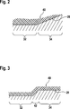
Zur Verdeutlichung dieses Verfahrens werden in den
In
Die Darstellungen der
Zum ersten Zeitpunkt in
Zum zweiten Zeitpunkt in
Zum dritten Zeitpunkt in
Zum vierten Zeitpunkt in
In Abschnitt b ist eine Szene dargestellt, aus der deutlich wird, dass sich die Hell-Dunkel-Grenze
In Abschnitt c ist der zu Abschnitt a komplementäre Fall dargestellt. Hier befindet sich die Hell-Dunkel-Grenze
Wie weiter aus Abschnitt b deutlich wird, befindet sich der Leuchtbereich bei korrekter Anordnung der Hell-Dunkel-Grenze
Innerhalb des Koordinatensystems
An der Stelle
An der Stelle
An der Stelle
An Stelle
An Stelle
Durch das qualitative Auswerten der einzelnen Bildbereiche
In einem Startpunkt
In einem Schritt
Anschließen erfolgt in Schritt
In einem weiteren Schritt
Ist dies nicht der Fall, wird in einem zusätzlichen Schritt
Wird in Schritt
In einem weiteren Schritt
In einem weiteren Schritt
In einem weiteren Schritt
In einem weiteren Schritt
Wird in Schritt
Das Verfahren endet in einem Schlussschritt
Die beschriebenen und in den Figuren gezeigten Ausführungsbeispiele sind nur beispielhaft gewählt. Unterschiedliche Ausführungsbeispiele können vollständig oder im Bezug auf die einzelnen Merkmale miteinander kombiniert werden. Auch kann ein Ausführungsbeispiel durch Merkmale eines weiteren Ausführungsbeispiels ergänzt werden.The embodiments described and shown in the figures are chosen only by way of example. Different embodiments may be combined with each other or with respect to the individual features. Also, an embodiment can be supplemented by features of another embodiment.
Ferner können erfindungsgemäße Verfahrensschritte wiederholt sowie in einer anderen als in der beschriebenen Reihenfolge ausgeführt werden.Furthermore, method steps according to the invention can be repeated as well as carried out in a sequence other than that described.
Umfasst ein Ausführungsbeispiel eine „und/oder“-Verknüpfung zwischen einem ersten und einem zweiten Merkmal, so ist dies so zu lesen, dass das Ausführungsbeispiel gemäß einer Ausführungsform sowohl das erste Merkmal als auch das zweite Merkmal und gemäß einer zweiten Ausführungsform entweder nur das erste Merkmal oder nur das zweite Merkmal aufweist.If an exemplary embodiment comprises a "and / or" link between a first and a second feature, this is to be read so that the embodiment according to an embodiment, both the first feature and the second feature and according to a second embodiment either only the first Feature or only the second feature.
Claims (14)
Priority Applications (6)
| Application Number | Priority Date | Filing Date | Title |
|---|---|---|---|
| DE102014219120.3A DE102014219120A1 (en) | 2013-12-19 | 2014-09-23 | Method and apparatus for determining headlamp leveling of a headlamp |
| US15/105,942 US9970752B2 (en) | 2013-12-19 | 2014-10-29 | Method and device for determining a headlight range alignment |
| JP2016530869A JP6348592B2 (en) | 2013-12-19 | 2014-10-29 | Method, control / evaluation unit, and computer program for adjusting irradiation area directivity of headlamp |
| CN201480069155.9A CN105829856B (en) | 2013-12-19 | 2014-10-29 | The method and apparatus oriented for determining the illumination zone of headlight |
| PCT/EP2014/073173 WO2015090699A1 (en) | 2013-12-19 | 2014-10-29 | Method and device for determining a beam width alignment of a headlight |
| EP14793830.2A EP3084385B1 (en) | 2013-12-19 | 2014-10-29 | Method and device for determining a beam width alignment of a headlight |
Applications Claiming Priority (3)
| Application Number | Priority Date | Filing Date | Title |
|---|---|---|---|
| DE102013226788 | 2013-12-19 | ||
| DE102013226788.6 | 2013-12-19 | ||
| DE102014219120.3A DE102014219120A1 (en) | 2013-12-19 | 2014-09-23 | Method and apparatus for determining headlamp leveling of a headlamp |
Publications (1)
| Publication Number | Publication Date |
|---|---|
| DE102014219120A1 true DE102014219120A1 (en) | 2015-06-25 |
Family
ID=51866144
Family Applications (1)
| Application Number | Title | Priority Date | Filing Date |
|---|---|---|---|
| DE102014219120.3A Withdrawn DE102014219120A1 (en) | 2013-12-19 | 2014-09-23 | Method and apparatus for determining headlamp leveling of a headlamp |
Country Status (6)
| Country | Link |
|---|---|
| US (1) | US9970752B2 (en) |
| EP (1) | EP3084385B1 (en) |
| JP (1) | JP6348592B2 (en) |
| CN (1) | CN105829856B (en) |
| DE (1) | DE102014219120A1 (en) |
| WO (1) | WO2015090699A1 (en) |
Cited By (2)
| Publication number | Priority date | Publication date | Assignee | Title |
|---|---|---|---|---|
| DE102016109030A1 (en) | 2016-05-17 | 2017-11-23 | Dr. Ing. H.C. F. Porsche Aktiengesellschaft | Method for evaluating a headlight |
| DE102016109027A1 (en) | 2016-05-17 | 2017-11-23 | Dr. Ing. H.C. F. Porsche Aktiengesellschaft | Method for checking the position of characteristic points in light distributions |
Families Citing this family (5)
| Publication number | Priority date | Publication date | Assignee | Title |
|---|---|---|---|---|
| JP2017505946A (en) * | 2014-01-17 | 2017-02-23 | ケーピーアイティ テクノロジーズ リミテッド | Vehicle detection system and method |
| DE102018204424B3 (en) * | 2018-03-22 | 2019-08-08 | Audi Ag | Method for calibrating a position of a matrix headlight of a motor vehicle, control device and motor vehicle |
| KR102812373B1 (en) * | 2019-12-03 | 2025-05-23 | 현대모비스 주식회사 | Headlamp leveling system |
| US12247881B2 (en) | 2020-08-25 | 2025-03-11 | Sapphire Ip, Inc. | Apparatus and method for measuring far-field luminous intensity and color characteristics of light sources |
| US12017577B2 (en) * | 2021-06-30 | 2024-06-25 | Apple Inc. | Vehicles with automatic headlight alignment |
Family Cites Families (18)
| Publication number | Priority date | Publication date | Assignee | Title |
|---|---|---|---|---|
| JPS6022641A (en) * | 1983-07-18 | 1985-02-05 | Toyota Motor Corp | Method and device for checking principal optical axis of head lamp |
| US4647195A (en) * | 1984-07-17 | 1987-03-03 | Toyota Jidosha Kabushiki Kaisha | Automotive headlamp testing method and apparatus |
| US5321439A (en) * | 1992-10-14 | 1994-06-14 | Environmental Systems Products, Inc. | Vehicle headlight testing system |
| JP2921404B2 (en) * | 1993-08-20 | 1999-07-19 | トヨタ自動車株式会社 | Headlight device for vehicles |
| US5633710A (en) * | 1995-10-04 | 1997-05-27 | Egs Inc. | System for self-aligning vehicle headlamps |
| DE102006016071B4 (en) * | 2006-04-04 | 2021-03-25 | Dr. Ing. H.C. F. Porsche Aktiengesellschaft | Control of the range of headlights of a motor vehicle |
| DE102008011699B4 (en) * | 2007-03-23 | 2015-09-24 | Volkswagen Ag | Method for determining a property for the operation of a motor vehicle and correspondingly designed motor vehicle |
| DE102008025458B4 (en) | 2008-05-28 | 2020-03-12 | HELLA GmbH & Co. KGaA | Method and device for calibrating a horizontal cut-off line generated by a headlight of a vehicle |
| DE102008060949B4 (en) | 2008-12-06 | 2023-09-28 | Mercedes-Benz Group AG | Method and arrangement for controlling vehicle headlights |
| DE102008063328A1 (en) * | 2008-12-30 | 2010-07-01 | Hella Kgaa Hueck & Co. | Method and device for determining a change in the pitch angle of a camera of a vehicle |
| DE102011109440A1 (en) | 2010-10-16 | 2012-04-19 | Daimler Ag | Method for adjusting and / or calibrating at least one headlight of a vehicle |
| DE102011006570A1 (en) * | 2011-03-31 | 2012-10-04 | Robert Bosch Gmbh | Method and control unit for transmitting data on a current vehicle environment to a headlight control unit of a vehicle |
| DE102011017697A1 (en) * | 2011-04-28 | 2012-10-31 | Robert Bosch Gmbh | Method for headlamp leveling at least one headlamp of a vehicle and light control device |
| JP5936098B2 (en) * | 2011-07-29 | 2016-06-15 | 株式会社リコー | Imaging apparatus, object detection apparatus including the same, and optical filter |
| DE102011081395A1 (en) * | 2011-08-23 | 2013-02-28 | Robert Bosch Gmbh | Method and control unit for adjusting a headlight range of a headlamp of a vehicle |
| DE102011081354B4 (en) | 2011-08-23 | 2025-05-15 | Robert Bosch Gmbh | Method for determining a road surface unevenness of a road section illuminated by at least one headlight of a vehicle and method for controlling a light emission of at least one headlight of a vehicle |
| DE102012102446A1 (en) | 2012-03-22 | 2013-09-26 | Hella Kgaa Hueck & Co. | Method for adjusting light device e.g. headlight of motor car, involves acquiring light distribution outside of light device using camera, and detecting features of light-dark boundaries on measuring wall |
| JP5555735B2 (en) * | 2012-03-27 | 2014-07-23 | 富士重工業株式会社 | Vehicle headlamp adjustment device |
-
2014
- 2014-09-23 DE DE102014219120.3A patent/DE102014219120A1/en not_active Withdrawn
- 2014-10-29 US US15/105,942 patent/US9970752B2/en active Active
- 2014-10-29 JP JP2016530869A patent/JP6348592B2/en active Active
- 2014-10-29 WO PCT/EP2014/073173 patent/WO2015090699A1/en not_active Ceased
- 2014-10-29 CN CN201480069155.9A patent/CN105829856B/en active Active
- 2014-10-29 EP EP14793830.2A patent/EP3084385B1/en active Active
Cited By (3)
| Publication number | Priority date | Publication date | Assignee | Title |
|---|---|---|---|---|
| DE102016109030A1 (en) | 2016-05-17 | 2017-11-23 | Dr. Ing. H.C. F. Porsche Aktiengesellschaft | Method for evaluating a headlight |
| DE102016109027A1 (en) | 2016-05-17 | 2017-11-23 | Dr. Ing. H.C. F. Porsche Aktiengesellschaft | Method for checking the position of characteristic points in light distributions |
| US10241000B2 (en) | 2016-05-17 | 2019-03-26 | Dr. Ing. H.C. F. Porsche Aktiengesellschaft | Method for checking the position of characteristic points in light distributions |
Also Published As
| Publication number | Publication date |
|---|---|
| US9970752B2 (en) | 2018-05-15 |
| WO2015090699A1 (en) | 2015-06-25 |
| JP6348592B2 (en) | 2018-06-27 |
| US20160320181A1 (en) | 2016-11-03 |
| JP2016540677A (en) | 2016-12-28 |
| CN105829856B (en) | 2019-08-20 |
| EP3084385B1 (en) | 2018-02-21 |
| CN105829856A (en) | 2016-08-03 |
| EP3084385A1 (en) | 2016-10-26 |
Similar Documents
| Publication | Publication Date | Title |
|---|---|---|
| EP3084385B1 (en) | Method and device for determining a beam width alignment of a headlight | |
| DE102018204424B3 (en) | Method for calibrating a position of a matrix headlight of a motor vehicle, control device and motor vehicle | |
| DE102008011699B4 (en) | Method for determining a property for the operation of a motor vehicle and correspondingly designed motor vehicle | |
| EP2701947B1 (en) | Method for adjusting the beam width of at least one headlight of a vehicle and light control device | |
| DE102011081354B4 (en) | Method for determining a road surface unevenness of a road section illuminated by at least one headlight of a vehicle and method for controlling a light emission of at least one headlight of a vehicle | |
| DE102010029149B4 (en) | Method and control unit for plausibility checking of a headlight range test value of a light cone of a vehicle headlight | |
| DE102008025459B4 (en) | Method and device for calibrating a vertical cut-off line generated by a headlight of a vehicle | |
| DE102008025458A1 (en) | Method and device for calibrating a horizontal cut-off line created by a headlight of a vehicle | |
| DE102016213028B4 (en) | Motor vehicle with one or more headlights | |
| DE102013216225B4 (en) | Method and device for controlling at least one headlight of a vehicle | |
| DE102010033351A1 (en) | Method for calibrating a vehicle system that actuates at least one headlight of a motor vehicle | |
| EP2562686A1 (en) | Method for determining an object class of an object, from which light is sent to a vehicle and/or reflected | |
| EP3014239B1 (en) | Method for checking the adjustment of a headlamp in a motor vehicle | |
| DE102011081392A1 (en) | Method for determining a headlight range of at least one headlight and method for calibrating a light emission of at least one headlight of a vehicle | |
| WO2012052187A1 (en) | Method and apparatus for checking a lighting driving assistance system | |
| DE102012102446A1 (en) | Method for adjusting light device e.g. headlight of motor car, involves acquiring light distribution outside of light device using camera, and detecting features of light-dark boundaries on measuring wall | |
| DE102013201382A1 (en) | Method for adjusting headlamp e.g. halogen bulbs of motor vehicle e.g. passenger car for reducing glare, involves adjusting illumination of headlamp of vehicle by using fading signal to adjust headlamps to reduce glare | |
| DE102017211699A1 (en) | Method for calibrating a lighting device | |
| DE102010035636B4 (en) | Device for changing from a high beam distribution to a light distribution that de-glares an object to be de-glared | |
| DE102010048689A1 (en) | Method for adjusting and/or calibrating headlight of motor vehicle, involves comparing determined global position at bright-dark-limit with reference position, and calibrating and/or adjusting headlight with determined deviation | |
| DE102008034166A1 (en) | Method and device for Euting a suitable light distribution of the light emitted by at least one headlight of a vehicle light | |
| DE102015012816A1 (en) | Method for calibrating a laser headlight in a motor vehicle and motor vehicle | |
| EP3598099B1 (en) | Method and systems for adjusting motor vehicle headlamps | |
| WO2011110203A1 (en) | Method for adjusting and/or calibrating an optical unit of a vehicle | |
| DE102014117844A1 (en) | Method for adjusting the headlight |
Legal Events
| Date | Code | Title | Description |
|---|---|---|---|
| R012 | Request for examination validly filed | ||
| R079 | Amendment of ipc main class |
Free format text: PREVIOUS MAIN CLASS: B60Q0001000000 Ipc: B60Q0001100000 |
|
| R119 | Application deemed withdrawn, or ip right lapsed, due to non-payment of renewal fee |