DE102014210638A1 - Injection module and exhaust system with injection module - Google Patents
Injection module and exhaust system with injection module Download PDFInfo
- Publication number
- DE102014210638A1 DE102014210638A1 DE102014210638.9A DE102014210638A DE102014210638A1 DE 102014210638 A1 DE102014210638 A1 DE 102014210638A1 DE 102014210638 A DE102014210638 A DE 102014210638A DE 102014210638 A1 DE102014210638 A1 DE 102014210638A1
- Authority
- DE
- Germany
- Prior art keywords
- injection module
- reducing agent
- outlet openings
- spray
- primary
- Prior art date
- Legal status (The legal status is an assumption and is not a legal conclusion. Google has not performed a legal analysis and makes no representation as to the accuracy of the status listed.)
- Withdrawn
Links
Images


Classifications
-
- F—MECHANICAL ENGINEERING; LIGHTING; HEATING; WEAPONS; BLASTING
- F01—MACHINES OR ENGINES IN GENERAL; ENGINE PLANTS IN GENERAL; STEAM ENGINES
- F01N—GAS-FLOW SILENCERS OR EXHAUST APPARATUS FOR MACHINES OR ENGINES IN GENERAL; GAS-FLOW SILENCERS OR EXHAUST APPARATUS FOR INTERNAL-COMBUSTION ENGINES
- F01N3/00—Exhaust or silencing apparatus having means for purifying, rendering innocuous, or otherwise treating exhaust
- F01N3/08—Exhaust or silencing apparatus having means for purifying, rendering innocuous, or otherwise treating exhaust for rendering innocuous
- F01N3/10—Exhaust or silencing apparatus having means for purifying, rendering innocuous, or otherwise treating exhaust for rendering innocuous by thermal or catalytic conversion of noxious components of exhaust
- F01N3/18—Exhaust or silencing apparatus having means for purifying, rendering innocuous, or otherwise treating exhaust for rendering innocuous by thermal or catalytic conversion of noxious components of exhaust characterised by methods of operation; Control
- F01N3/20—Exhaust or silencing apparatus having means for purifying, rendering innocuous, or otherwise treating exhaust for rendering innocuous by thermal or catalytic conversion of noxious components of exhaust characterised by methods of operation; Control specially adapted for catalytic conversion
- F01N3/206—Adding periodically or continuously substances to exhaust gases for promoting purification, e.g. catalytic material in liquid form, NOx reducing agents
- F01N3/2066—Selective catalytic reduction [SCR]
-
- F—MECHANICAL ENGINEERING; LIGHTING; HEATING; WEAPONS; BLASTING
- F01—MACHINES OR ENGINES IN GENERAL; ENGINE PLANTS IN GENERAL; STEAM ENGINES
- F01N—GAS-FLOW SILENCERS OR EXHAUST APPARATUS FOR MACHINES OR ENGINES IN GENERAL; GAS-FLOW SILENCERS OR EXHAUST APPARATUS FOR INTERNAL-COMBUSTION ENGINES
- F01N2610/00—Adding substances to exhaust gases
- F01N2610/02—Adding substances to exhaust gases the substance being ammonia or urea
-
- F—MECHANICAL ENGINEERING; LIGHTING; HEATING; WEAPONS; BLASTING
- F01—MACHINES OR ENGINES IN GENERAL; ENGINE PLANTS IN GENERAL; STEAM ENGINES
- F01N—GAS-FLOW SILENCERS OR EXHAUST APPARATUS FOR MACHINES OR ENGINES IN GENERAL; GAS-FLOW SILENCERS OR EXHAUST APPARATUS FOR INTERNAL-COMBUSTION ENGINES
- F01N2610/00—Adding substances to exhaust gases
- F01N2610/14—Arrangements for the supply of substances, e.g. conduits
- F01N2610/1453—Sprayers or atomisers; Arrangement thereof in the exhaust apparatus
-
- Y—GENERAL TAGGING OF NEW TECHNOLOGICAL DEVELOPMENTS; GENERAL TAGGING OF CROSS-SECTIONAL TECHNOLOGIES SPANNING OVER SEVERAL SECTIONS OF THE IPC; TECHNICAL SUBJECTS COVERED BY FORMER USPC CROSS-REFERENCE ART COLLECTIONS [XRACs] AND DIGESTS
- Y02—TECHNOLOGIES OR APPLICATIONS FOR MITIGATION OR ADAPTATION AGAINST CLIMATE CHANGE
- Y02T—CLIMATE CHANGE MITIGATION TECHNOLOGIES RELATED TO TRANSPORTATION
- Y02T10/00—Road transport of goods or passengers
- Y02T10/10—Internal combustion engine [ICE] based vehicles
- Y02T10/12—Improving ICE efficiencies
Landscapes
- Chemical & Material Sciences (AREA)
- Engineering & Computer Science (AREA)
- Chemical Kinetics & Catalysis (AREA)
- Health & Medical Sciences (AREA)
- Toxicology (AREA)
- Combustion & Propulsion (AREA)
- Mechanical Engineering (AREA)
- General Engineering & Computer Science (AREA)
- Exhaust Gas After Treatment (AREA)
- Exhaust Gas Treatment By Means Of Catalyst (AREA)
Abstract
Ein Einspritzmodul (10) zum Einspritzen eines Reduktionsmittels in den Abgasstrang (22) eines Verbrennungsmotors (2) hat wenigstens zwei Austrittsöffnungen (12) zur Ausgabe wenigstens eines Reduktionsmittel-Primärstrahls (13), wobei die Austrittsöffnungen (12) derart ausgebildet sind, dass die durch die Austrittsöffnungen (12) austretenden Reduktionsmittel-Primärstrahlen (13) aufeinander treffen, um im Abgasstrang (22) einen Sprühnebel (11) zu erzeugen.An injection module (10) for injecting a reducing agent into the exhaust line (22) of an internal combustion engine (2) has at least two outlet openings (12) for emitting at least one reducing agent primary jet (13), wherein the outlet openings (12) are formed such that the through the outlet openings (12) emerging reductant primary beams (13) meet to produce a spray (11) in the exhaust line (22).

Description
Die Erfindung betrifft ein Einspritzmodul, insbesondere ein Einspritzmodul zum Einspritzen eines Reduktionsmittels in den Abgasstrang eines Verbrennungsmotors, und einen Abgasstrang, der mit einem derartigen Einspritzmodul ausgestattet ist.The invention relates to an injection module, in particular an injection module for injecting a reducing agent into the exhaust gas line of an internal combustion engine, and an exhaust gas line, which is equipped with such an injection module.
Stand der TechnikState of the art
Zum Entsticken der Abgase von Dieselmotoren hat sich die SCR-Technik („selective catalytic reduction“) unter Einsatz eines harnstoffhaltigen flüssigen Reduktionsmittels („AdBlue®“) bewährt. Hierbei wird das flüssige Reduktionsmittel, eine wässrige Harnstofflösung, stromaufwärts eines Reduktionsmittelkatalysator in den Abgasstrom eingesprüht und dabei fein zerstäubt, bevor das Abgas-Reduktionsmittel-Gemisch dem SCR-Katalysator zugeführt wird.In order to de-sting the exhaust gases of diesel engines, the SCR technique ("selective catalytic reduction") using a urea-containing liquid reducing agent ("AdBlue ® ") has proven itself. Here, the liquid reducing agent, an aqueous urea solution upstream of a reducing agent catalyst is sprayed into the exhaust gas stream and thereby finely atomized before the exhaust gas reducing agent mixture is supplied to the SCR catalyst.
Um einen hohen Umsetzungsgrad der Stickoxide bei möglichst geringem Reduktionsmittelschlupf zu erreichen, muss das Reduktionsmittel möglichst homogen auf der Eintrittsfläche des Katalysators verteilt werden. Dies wird bisher entweder durch im Abgasrohr angebrachte Mischer oder durch eine lange Mischstrecke zwischen der Stelle, an der das Reduktionsmittel eindosiert wird, und dem Katalysator erreicht. In order to achieve a high degree of conversion of the nitrogen oxides with the lowest possible reducing agent slip, the reducing agent must be distributed as homogeneously as possible on the inlet surface of the catalyst. This has hitherto been achieved either by means of mixers mounted in the exhaust pipe or by a long mixing path between the point at which the reducing agent is metered in and the catalyst.
Um die erwünschte Homogenisierung des Reduktionsmittels mit dem Abgas zu erreichen, ist ein möglichst flacher, aber vollflächiger Reduktionsmittel-Sprühnebel („Reduktionsmittel-Spray“) erforderlich. Um unerwünschte Ablagerungen des Reduktionsmittels in der Abgasanlage zu vermeiden, darf nur eine begrenzte Menge des Reduktionsmittels auf die Wände der Abgasanlage treffen.In order to achieve the desired homogenization of the reducing agent with the exhaust gas, a flat as possible, but full-surface reductant spray ("reducing agent spray") is required. In order to avoid undesirable deposits of the reducing agent in the exhaust system, only a limited amount of the reducing agent must hit the walls of the exhaust system.
Offenbarung der ErfindungDisclosure of the invention
Eine Aufgabe der Erfindung besteht darin, den durch eine Strahlkollision im Abgasstrang erzeugten Sprühnebel zu optimieren und insbesondere einen möglichst vollflächigen Sprühnebel („Spray“) mit einer möglichst homogenen Massenverteilung zu erzeugen.An object of the invention is to optimize the spray mist generated by a jet collision in the exhaust system and in particular to produce a spray as full as possible ("spray") with a very homogeneous mass distribution.
Ein erfindungsgemäßes Einspritzmodul zum Einspritzen eines Reduktionsmittels in den Abgasstrang eines Verbrennungsmotors hat wenigstens zwei Austrittsöffnungen zur Ausgabe jeweils wenigstens eines Reduktionsmittel-Primärstrahls. An injection module according to the invention for injecting a reducing agent into the exhaust gas line of an internal combustion engine has at least two outlet openings for dispensing in each case at least one reducing agent primary jet.
Dabei sind die Austrittsöffnungen derart ausgebildet, dass die durch die wenigstens zwei Austrittsöffnungen austretenden Reduktionsmittel-Primärstrahlen nicht vollflächig, sondern nur teilweise überlappend, aufeinander treffen, um durch die Kollision einen Sprühnebel im Abgasstrang zu erzeugen.In this case, the outlet openings are formed such that the emerging through the at least two outlet openings reducing agent primary rays not over the entire surface, but only partially overlapping, meet each other to produce by the collision a spray in the exhaust system.
Die Erfindung umfasst auch ein Verfahren des Einspritzens eines Reduktionsmittels in den Abgasstrang eines Verbrennungsmotors, wobei das Verfahren einschließt, wenigstens zwei Reduktionsmittel-Primärstrahlen so in den Abgasstrang einzuspritzen, dass sie nicht vollflächig sondern nur teilweise überlappend aufeinander treffen, um einen geeigneten Sprühnebel im Abgasstrang zu erzeugen.The invention also includes a method of injecting a reductant into the exhaust line of an internal combustion engine, the method including injecting at least two reductant primary jets into the exhaust line such that they do not strike each other over the entire surface but only partially overlapping each other to provide a suitable spray in the exhaust line produce.
Auf diese Weise wird durch Strahlkollision im Abgasstrang ein flacher, vollflächiger Reduktionsmittel-Sprühnebel mit einer sehr homogenen Massenverteilung erzeugt, der sich optimal mit den durch den Abgasstrang strömenden Abgasen vermischt und so bei geringem Reduktionsmittelverbrauch eine effektive Schadstoffreduktion ermöglicht.In this way, by beam collision in the exhaust line a flat, full-surface Reducing agent spray generated with a very homogeneous mass distribution, which optimally mixed with the exhaust gases flowing through the exhaust line and thus allows for low reducing agent consumption effective pollutant reduction.
Um das erfindungsgemäße teilweise überlappende Aufeinandertreffen der Reduktionsmittel-Primärstrahlen zu verwirklichen, können die Austrittsöffnungen insbesondere gegeneinander versetzt und/oder gegeneinander verkippt angeordnet sein. Durch eine gegeneinander versetzte und/oder gegeneinander verkippte Anordnung der Austrittsöffnungen kann effektiv und mit einfachen Mitteln ein teilweise überlappendes Aufeinandertreffen der Reduktionsmittel-Primärstrahlen erreicht werden.In order to realize the inventive partially overlapping meeting of the reductant primary rays, the outlet openings can in particular be offset from one another and / or tilted relative to one another. By a mutually offset and / or mutually tilted arrangement of the outlet openings, a partially overlapping meeting of the reducing agent primary radiation can be achieved effectively and by simple means.
In einer Ausführungsform liegt die Überdeckung im Bereich von 30% bis 70%, insbesondere in einem Bereich von 40% bis 60% der Fläche der Primärstrahlen. Eine Überdeckung in diesem Bereich hat sich als besonders vorteilhaft für die Erzeugung eines möglichst homogenen Sprühnebels erwiesen.In one embodiment, the coverage is in the range of 30% to 70%, more preferably in a range of 40% to 60% of the area of the primary beams. An overlap in this area has proved to be particularly advantageous for the production of a spray as homogeneous as possible.
In einer Ausführungsform haben die Austrittsöffnungen einen Abstand von weniger als 5 mm, insbesondere von weniger als 2 mm, voneinander, so dass die Primärstrahlen von ihrer jeweiligen Austrittsöffnung bis zum Kollisionspunkt kompakte Strahlen sind, die noch nicht in einzelne Tropfen zerfallen sind. Sind die Primärstrahlen bereits in einzelne Tropfen zerfallen, fehlen einzelnen Tropfen immer wieder Kollisionspartner; durch kompakte Strahlen wird die Kollision daher optimiert.In one embodiment, the exit orifices are spaced less than 5mm apart, more preferably less than 2mm apart, such that the primary jets from their respective exit ports to the point of collision are compact jets that have not yet disintegrated into individual drops. If the primary rays have already disintegrated into individual drops, individual drops are always missing collision partners; compact collision therefore optimizes the collision.
In einer Ausführungsform sind die Austrittsöffnungen so ausgebildet, dass die Reduktionsmittel-Primärstrahlen in einem Winkel von mehr als 30° aufeinander treffen, um die Kollision zwischen den beiden Primärstrahlen zu optimieren und eine optimale Zerstäubung der Primärstrahlen zu bewirken.In one embodiment, the exit orifices are configured such that the reductant primary jets meet at an angle greater than 30 ° to optimize the collision between the two primary jets and to provide optimum atomization of the primary jets.
In einer Ausführungsform sind die Austrittsöffnungen so ausgebildet, dass die Reduktionsmittel-Primärstrahlen nach einer freien Wegstrecke von weniger als 10 mm, insbesondere von weniger als 5 mm, aufeinander treffen, um zu vermeiden, dass die Primärstrahlen vor dem Kollisionspunkt in einzelne Tropfen aufreißen.In one embodiment, the outlet openings are formed so that the reducing agent primary rays meet after a free distance of less than 10 mm, in particular less than 5 mm, in order to avoid that the primary rays tore into individual drops before the collision point.
Die Austrittsöffnungen haben vorzugsweise einen kreisrunden Querschnitt, da der Strahldurchmesser und der Austrittswinkel des Strahls bei einem kreisrunden Querschnitt genau definiert sind. Die Austrittsöffnungen können aber auch mit einem ovalen Querschnitt ausgebildet sein.The outlet openings preferably have a circular cross-section, since the jet diameter and the exit angle of the jet are precisely defined in the case of a circular cross-section. The outlet openings may also be formed with an oval cross-section.
Die Erfindung umfasst auch einen Abschnitt eines Abgasstrangs eines Verbrennungsmotors in dem ein erfindungsgemäßes Einspritzmodul vorgesehen ist.The invention also includes a portion of an exhaust line of an internal combustion engine in which an injection module according to the invention is provided.
In einer Ausführungsform weist der Abschnitt des Abgasstrangs zusätzlich zum Einspritzmodul ein Abschirmblech auf, das derart ausgebildet und angeordnet ist, dass es ein Auftreffen des Sprühnebels auf eine Wand des Abgasstranges verhindert. Unerwünschte Ablagerungen des Reduktionsmittels, welche die Strömungseigenschaften im Abgasstrang negativ beeinflussen können, werden auf diese Weise zuverlässig verhindert.In one embodiment, in addition to the injection module, the section of the exhaust gas line has a shielding plate, which is designed and arranged such that it prevents the spray from hitting a wall of the exhaust line. Unwanted deposits of the reducing agent, which can adversely affect the flow properties in the exhaust system, are reliably prevented in this way.
Das Abschirmblech kann eine oder mehrere Öffnungen aufweisen, die eine definierte Strömung der Abgase durch das Abschirmblech ermöglichen, um das Strömungsverhalten der Abgase im Abgasstrang gezielt zu beeinflussen.The shielding plate may have one or more openings which allow a defined flow of the exhaust gases through the shielding plate in order to influence the flow behavior of the exhaust gases in the exhaust system in a targeted manner.
In einer Ausführungsform ist das Abschirmblech so angeordnet, dass zwischen dem Abschirmblech und wenigstens einer Wand des Abgasstrangs ein Stauraum ausgebildet ist. Im Betrieb entsteht im Stauraum ein Abgas-Überdruck, der eine Strömung von Abgasen durch im Abschirmblech ausgebildete Löcher bewirkt, was eine besonders effektive Vermischung der Abgase mit dem erfindungsgemäß zerstäubten Reduktionsmittel zur Folge hat.In one embodiment, the shielding plate is arranged such that a storage space is formed between the shielding plate and at least one wall of the exhaust gas line. In operation, an exhaust gas overpressure arises in the storage space, which causes a flow of exhaust gases through holes formed in the shielding plate, which results in a particularly effective mixing of the exhaust gases with the atomized reducing agent according to the invention.
In einer Ausführungsform ist ein zusätzliches Blech stromaufwärts des Einspritzmoduls angeordnet, um zu verhindern, dass der Reduktionsmittel-Sprühnebel an der Kollisionsstelle der Primärstrahlen durch die Abgasströmung verweht wird, und so eine sichere Sprühnebel-Erzeugung durch die Primärstrahlen zu gewährleisten.In one embodiment, an additional plate is disposed upstream of the injection module to prevent the reductant spray at the collision point of the primary jets from being blown by the exhaust gas flow, thus ensuring safe spray generation by the primary jets.
In einer Ausführungsform sind stromaufwärts des Einspritzmoduls ein Oxidationskatalysator und stromabwärts des Einspritzmoduls ein Reduktionskatalysator angeordnet, um eine optimale Abgasreinigung zu bewirken. Das Einspritzmodul ist insbesondere in einem Verbindungskanal angeordnet, der den Ausgang des Oxidationskatalysators mit dem Eingang des Reduktionskatalysators strömungsmäßig verbindet, um das Reduktionsmittel den Abgasen unmittelbar vor dem Reduktionskatalysator zuzuführen.In one embodiment, upstream of the injection module, an oxidation catalyst and downstream of the injection module, a reduction catalyst are arranged to effect optimum exhaust gas purification. In particular, the injection module is arranged in a connection channel which connects the outlet of the oxidation catalyst to the inlet of the reduction catalyst in order to supply the reducing agent to the exhaust gases immediately before the reduction catalyst.
In einer Ausführungsform wird die Strömungsrichtung der Abgase durch den Verbindungskanal geändert. Dies ermöglicht eine besonders kompakte Bauform des Abgasstrangs und bewirkt eine Verwirbelung der Abgasströmung. Eine solche Verwirbelung der Abgasströmung hat eine besonders effektive Vermischung der Abgase mit dem Reduktionsmittel-Sprühnebel zur Folge.In one embodiment, the flow direction of the exhaust gases is changed by the connection channel. This allows a particularly compact design of the exhaust system and causes a turbulence of the exhaust gas flow. Such turbulence of the exhaust gas flow results in a particularly effective mixing of the exhaust gases with the reducing agent spray.
Kurze Beschreibung der Figuren: Brief description of the figures:
Figurenbeschreibung:Brief Description:
Frischluft
Neben dem Oxidationskatalysator
An dem Verbindungskanal
Das Einspritzmodul
Um zu verhindern, dass der Reduktionsmittel-Sprühnebel
Durch in dem Abschirmblech
Ein zusätzliches Ablenkblech
Die aus den Austrittsöffnungen
Der Abstand d zwischen den Austrittsöffnungen
Die Austrittsöffnungen
Es können auch weitere, in der
In einer Ausführungsform sind die Austrittsöffnungen
In einer Ausführungsform sind die Austrittsöffnungen
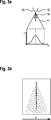
In der
Die Pfeile
In der
Auch ein auf diese Weise erzeugter Sprühnebel
Im Fall geringer Überdeckung der Primärstrahlen ist der größte Massenanteil des Reduktionsmittels an den Rändern des Sprühnebels
Sowohl im graphischen Diagramm der
In der
Durch die größere, aber nicht vollständige Überdeckung der beiden Primärstrahlen
Unterhalb des Sprühnebels
Sowohl im graphischen Diagramm der
Als besonders geeignet hat sich eine Überdeckung der Primärstrahlen
ZITATE ENTHALTEN IN DER BESCHREIBUNG QUOTES INCLUDE IN THE DESCRIPTION
Diese Liste der vom Anmelder aufgeführten Dokumente wurde automatisiert erzeugt und ist ausschließlich zur besseren Information des Lesers aufgenommen. Die Liste ist nicht Bestandteil der deutschen Patent- bzw. Gebrauchsmusteranmeldung. Das DPMA übernimmt keinerlei Haftung für etwaige Fehler oder Auslassungen.This list of the documents listed by the applicant has been generated automatically and is included solely for the better information of the reader. The list is not part of the German patent or utility model application. The DPMA assumes no liability for any errors or omissions.
Zitierte PatentliteraturCited patent literature
- DE 4417238 A1 [0004] DE 4417238 A1 [0004]
- DE 102010039079 A1 [0005] DE 102010039079 A1 [0005]
- DE 102013223296 [0007] DE 102013223296 [0007]
Claims (10)
Priority Applications (6)
| Application Number | Priority Date | Filing Date | Title |
|---|---|---|---|
| DE102014210638.9A DE102014210638A1 (en) | 2014-06-04 | 2014-06-04 | Injection module and exhaust system with injection module |
| PCT/EP2015/059357 WO2015185297A1 (en) | 2014-06-04 | 2015-04-29 | Injection module and exhaust system having an injection module |
| CN201580029512.3A CN106536882A (en) | 2014-06-04 | 2015-04-29 | Injection module and exhaust system having an injection module |
| KR1020177000294A KR20170015480A (en) | 2014-06-04 | 2015-04-29 | Injection module and exhaust system having an injection module |
| US15/315,564 US20180142596A1 (en) | 2014-06-04 | 2015-04-29 | Injection module and exhaust system having an injection module |
| EP15720324.1A EP3152420B1 (en) | 2014-06-04 | 2015-04-29 | Injection module and exhaust system having an injection module |
Applications Claiming Priority (1)
| Application Number | Priority Date | Filing Date | Title |
|---|---|---|---|
| DE102014210638.9A DE102014210638A1 (en) | 2014-06-04 | 2014-06-04 | Injection module and exhaust system with injection module |
Publications (1)
| Publication Number | Publication Date |
|---|---|
| DE102014210638A1 true DE102014210638A1 (en) | 2015-12-17 |
Family
ID=53051817
Family Applications (1)
| Application Number | Title | Priority Date | Filing Date |
|---|---|---|---|
| DE102014210638.9A Withdrawn DE102014210638A1 (en) | 2014-06-04 | 2014-06-04 | Injection module and exhaust system with injection module |
Country Status (6)
| Country | Link |
|---|---|
| US (1) | US20180142596A1 (en) |
| EP (1) | EP3152420B1 (en) |
| KR (1) | KR20170015480A (en) |
| CN (1) | CN106536882A (en) |
| DE (1) | DE102014210638A1 (en) |
| WO (1) | WO2015185297A1 (en) |
Families Citing this family (3)
| Publication number | Priority date | Publication date | Assignee | Title |
|---|---|---|---|---|
| CN110573242B (en) * | 2017-04-20 | 2022-03-22 | 沃尔沃遍达公司 | Mixer device, use of mixer device and method for mixing |
| DE102019207697A1 (en) * | 2019-05-27 | 2020-12-03 | Robert Bosch Gmbh | Injection module for a reducing agent |
| JP7619092B2 (en) | 2021-03-05 | 2025-01-22 | マツダ株式会社 | Engine exhaust purification device |
Citations (3)
| Publication number | Priority date | Publication date | Assignee | Title |
|---|---|---|---|---|
| DE4417238A1 (en) | 1994-05-17 | 1994-09-29 | Siemens Ag | Device for reducing the amount of nitrogen oxides in the exhaust from a lean-burn internal-combustion engine |
| DE102010039079A1 (en) | 2010-08-09 | 2012-02-09 | Robert Bosch Gmbh | Injection apparatus for injecting fluid into exhaust system of diesel engine for motor car, has perforated plate whose injection hole is designed such that fluid flows through hole in flow direction that is directed towards valve axis |
| DE102013223296A1 (en) | 2013-11-15 | 2015-05-21 | Robert Bosch Gmbh | Injection module and exhaust system with injection module |
Family Cites Families (8)
| Publication number | Priority date | Publication date | Assignee | Title |
|---|---|---|---|---|
| JP2005155404A (en) * | 2003-11-25 | 2005-06-16 | Komatsu Ltd | Exhaust gas purification device for internal combustion engine |
| JP5188961B2 (en) * | 2005-05-20 | 2013-04-24 | グルンドフォス ノノックス エー/エス | Fluid atomization method by mutual collision of fluid streams, nozzle therefor, and system including the same |
| DE102011018569A1 (en) * | 2011-04-26 | 2012-10-31 | Audi Ag | Exhaust system for use in combustion engine of motor car, has metering valve injecting reducing agent in passage portion arranged in baffle unit, where baffle unit comprises impact surfaces that are bent in main flow direction of gas stream |
| WO2012157066A1 (en) * | 2011-05-16 | 2012-11-22 | トヨタ自動車株式会社 | Exhaust purifying apparatus for internal combustion engine |
| JP5295316B2 (en) * | 2011-06-22 | 2013-09-18 | 三菱電機株式会社 | Spray generation method using fluid injection valve, fluid injection valve, and spray generation device |
| JP5349576B2 (en) * | 2011-12-27 | 2013-11-20 | 株式会社小松製作所 | Reducing agent aqueous solution mixing device and exhaust gas aftertreatment device |
| US8932530B2 (en) * | 2011-12-27 | 2015-01-13 | Komatsu Ltd. | Reducing agent aqueous solution mixing device and exhaust gas post-treatment device |
| WO2014080265A1 (en) * | 2012-11-20 | 2014-05-30 | Nostrum Energy Pte. Ltd. | Liquid injector atomizer with colliding jets |
-
2014
- 2014-06-04 DE DE102014210638.9A patent/DE102014210638A1/en not_active Withdrawn
-
2015
- 2015-04-29 KR KR1020177000294A patent/KR20170015480A/en not_active Withdrawn
- 2015-04-29 CN CN201580029512.3A patent/CN106536882A/en active Pending
- 2015-04-29 WO PCT/EP2015/059357 patent/WO2015185297A1/en not_active Ceased
- 2015-04-29 EP EP15720324.1A patent/EP3152420B1/en not_active Not-in-force
- 2015-04-29 US US15/315,564 patent/US20180142596A1/en not_active Abandoned
Patent Citations (3)
| Publication number | Priority date | Publication date | Assignee | Title |
|---|---|---|---|---|
| DE4417238A1 (en) | 1994-05-17 | 1994-09-29 | Siemens Ag | Device for reducing the amount of nitrogen oxides in the exhaust from a lean-burn internal-combustion engine |
| DE102010039079A1 (en) | 2010-08-09 | 2012-02-09 | Robert Bosch Gmbh | Injection apparatus for injecting fluid into exhaust system of diesel engine for motor car, has perforated plate whose injection hole is designed such that fluid flows through hole in flow direction that is directed towards valve axis |
| DE102013223296A1 (en) | 2013-11-15 | 2015-05-21 | Robert Bosch Gmbh | Injection module and exhaust system with injection module |
Also Published As
| Publication number | Publication date |
|---|---|
| KR20170015480A (en) | 2017-02-08 |
| EP3152420A1 (en) | 2017-04-12 |
| US20180142596A1 (en) | 2018-05-24 |
| EP3152420B1 (en) | 2019-04-10 |
| WO2015185297A1 (en) | 2015-12-10 |
| CN106536882A (en) | 2017-03-22 |
Similar Documents
| Publication | Publication Date | Title |
|---|---|---|
| DE102019210877A1 (en) | Mixer and exhaust gas aftertreatment system | |
| DE112012006957B4 (en) | Metering device and mixing device for a vehicle exhaust system | |
| DE102012016423B3 (en) | Exhaust system with mixing and or evaporation device | |
| DE112006000518B4 (en) | Exhaust system with injection nozzle | |
| EP2570178B1 (en) | Mixing device | |
| WO2008135112A1 (en) | Device and method for metering liquid pollutant-reducing media into an exhaust gas duct of an internal combustion engine | |
| DE102016222743A1 (en) | Integrated exhaust aftertreatment system | |
| EP1404949A1 (en) | Mixing device for an exhaust gas purification system | |
| WO2015018849A1 (en) | Mixing chamber | |
| DE112017007996T5 (en) | Injector cone like a Venturi nozzle | |
| DE112014003949T5 (en) | Exhaust gas purification device for internal combustion engine | |
| DE112009001055T5 (en) | Exhaust element comprising a static means for admixing an additive to exhaust gases | |
| DE112017007988T5 (en) | COMPACT MIXER WITH FLOW Diverter | |
| DE112020004364T5 (en) | EXHAUST AND REDUCING AGENT MIXER FOR AN AFTERTREATMENT SYSTEM | |
| DE2645142A1 (en) | METHOD FOR GENERATING MIXED AND ATOMIZED FLUIDA AND DEVICE FOR CARRYING OUT THE METHOD | |
| DE102010002245C5 (en) | Exhaust pipe arrangement of an internal combustion engine | |
| DE102014102798A1 (en) | Exhaust treatment device | |
| DE102019130972A1 (en) | REDUCING AGENT NOZZLE WITH SPACE-SHAPED CHANNEL DESIGN | |
| DE102022121551A1 (en) | Mixer, mixer assembly and mixing method | |
| EP3152420B1 (en) | Injection module and exhaust system having an injection module | |
| EP3068986B1 (en) | Injection module and exhaust system having an injection module | |
| DE102014223382A1 (en) | Method for operating a device for aftertreatment of the exhaust gases of an internal combustion engine and corresponding device | |
| DE102012014528A1 (en) | Mixing- or evaporation device for exhaust system of internal combustion engine, particularly of motor vehicle, has guide blade that protrudes in direction towards long side wall, where additional guide blade protrudes in acute angle | |
| DE112022006302T5 (en) | SCR MIXER AND MOTOR | |
| DE102017125619A1 (en) | Exhaust system for compact and efficient after-treatment and noise reduction of the exhaust gas |
Legal Events
| Date | Code | Title | Description |
|---|---|---|---|
| R119 | Application deemed withdrawn, or ip right lapsed, due to non-payment of renewal fee |