DE102014115048A1 - Terminal device with a busbar - Google Patents
Terminal device with a busbar Download PDFInfo
- Publication number
- DE102014115048A1 DE102014115048A1 DE102014115048.1A DE102014115048A DE102014115048A1 DE 102014115048 A1 DE102014115048 A1 DE 102014115048A1 DE 102014115048 A DE102014115048 A DE 102014115048A DE 102014115048 A1 DE102014115048 A1 DE 102014115048A1
- Authority
- DE
- Germany
- Prior art keywords
- busbar
- clamping device
- housing
- slot
- contact part
- Prior art date
- Legal status (The legal status is an assumption and is not a legal conclusion. Google has not performed a legal analysis and makes no representation as to the accuracy of the status listed.)
- Ceased
Links
- 238000003780 insertion Methods 0.000 claims description 11
- 230000037431 insertion Effects 0.000 claims description 11
- 239000004020 conductor Substances 0.000 claims description 7
- 230000006866 deterioration Effects 0.000 description 3
- 239000012777 electrically insulating material Substances 0.000 description 3
- RYGMFSIKBFXOCR-UHFFFAOYSA-N Copper Chemical compound [Cu] RYGMFSIKBFXOCR-UHFFFAOYSA-N 0.000 description 2
- 229910052802 copper Inorganic materials 0.000 description 2
- 239000010949 copper Substances 0.000 description 2
- 238000010438 heat treatment Methods 0.000 description 2
- 230000007704 transition Effects 0.000 description 2
- BUHVIAUBTBOHAG-FOYDDCNASA-N (2r,3r,4s,5r)-2-[6-[[2-(3,5-dimethoxyphenyl)-2-(2-methylphenyl)ethyl]amino]purin-9-yl]-5-(hydroxymethyl)oxolane-3,4-diol Chemical compound COC1=CC(OC)=CC(C(CNC=2C=3N=CN(C=3N=CN=2)[C@H]2[C@@H]([C@H](O)[C@@H](CO)O2)O)C=2C(=CC=CC=2)C)=C1 BUHVIAUBTBOHAG-FOYDDCNASA-N 0.000 description 1
- 238000010276 construction Methods 0.000 description 1
- 230000006735 deficit Effects 0.000 description 1
- 230000007613 environmental effect Effects 0.000 description 1
- 230000001771 impaired effect Effects 0.000 description 1
- 210000002414 leg Anatomy 0.000 description 1
- 238000004519 manufacturing process Methods 0.000 description 1
- 239000000463 material Substances 0.000 description 1
- 239000002184 metal Substances 0.000 description 1
- 229910052751 metal Inorganic materials 0.000 description 1
- 210000000689 upper leg Anatomy 0.000 description 1
Images

Classifications
-
- H—ELECTRICITY
- H01—ELECTRIC ELEMENTS
- H01R—ELECTRICALLY-CONDUCTIVE CONNECTIONS; STRUCTURAL ASSOCIATIONS OF A PLURALITY OF MUTUALLY-INSULATED ELECTRICAL CONNECTING ELEMENTS; COUPLING DEVICES; CURRENT COLLECTORS
- H01R9/00—Structural associations of a plurality of mutually-insulated electrical connecting elements, e.g. terminal strips or terminal blocks; Terminals or binding posts mounted upon a base or in a case; Bases therefor
- H01R9/22—Bases, e.g. strip, block, panel
- H01R9/24—Terminal blocks
- H01R9/26—Clip-on terminal blocks for side-by-side rail- or strip-mounting
- H01R9/2675—Electrical interconnections between two blocks, e.g. by means of busbars
-
- H—ELECTRICITY
- H01—ELECTRIC ELEMENTS
- H01R—ELECTRICALLY-CONDUCTIVE CONNECTIONS; STRUCTURAL ASSOCIATIONS OF A PLURALITY OF MUTUALLY-INSULATED ELECTRICAL CONNECTING ELEMENTS; COUPLING DEVICES; CURRENT COLLECTORS
- H01R4/00—Electrically-conductive connections between two or more conductive members in direct contact, i.e. touching one another; Means for effecting or maintaining such contact; Electrically-conductive connections having two or more spaced connecting locations for conductors and using contact members penetrating insulation
- H01R4/24—Connections using contact members penetrating or cutting insulation or cable strands
- H01R4/2416—Connections using contact members penetrating or cutting insulation or cable strands the contact members having insulation-cutting edges, e.g. of tuning fork type
- H01R4/242—Connections using contact members penetrating or cutting insulation or cable strands the contact members having insulation-cutting edges, e.g. of tuning fork type the contact members being plates having a single slot
-
- H—ELECTRICITY
- H01—ELECTRIC ELEMENTS
- H01R—ELECTRICALLY-CONDUCTIVE CONNECTIONS; STRUCTURAL ASSOCIATIONS OF A PLURALITY OF MUTUALLY-INSULATED ELECTRICAL CONNECTING ELEMENTS; COUPLING DEVICES; CURRENT COLLECTORS
- H01R4/00—Electrically-conductive connections between two or more conductive members in direct contact, i.e. touching one another; Means for effecting or maintaining such contact; Electrically-conductive connections having two or more spaced connecting locations for conductors and using contact members penetrating insulation
- H01R4/28—Clamped connections, spring connections
- H01R4/48—Clamped connections, spring connections utilising a spring, clip, or other resilient member
- H01R4/4809—Clamped connections, spring connections utilising a spring, clip, or other resilient member using a leaf spring to bias the conductor toward the busbar
- H01R4/4846—Busbar details
-
- H—ELECTRICITY
- H01—ELECTRIC ELEMENTS
- H01R—ELECTRICALLY-CONDUCTIVE CONNECTIONS; STRUCTURAL ASSOCIATIONS OF A PLURALITY OF MUTUALLY-INSULATED ELECTRICAL CONNECTING ELEMENTS; COUPLING DEVICES; CURRENT COLLECTORS
- H01R9/00—Structural associations of a plurality of mutually-insulated electrical connecting elements, e.g. terminal strips or terminal blocks; Terminals or binding posts mounted upon a base or in a case; Bases therefor
- H01R9/22—Bases, e.g. strip, block, panel
- H01R9/24—Terminal blocks
- H01R9/26—Clip-on terminal blocks for side-by-side rail- or strip-mounting
-
- H—ELECTRICITY
- H01—ELECTRIC ELEMENTS
- H01R—ELECTRICALLY-CONDUCTIVE CONNECTIONS; STRUCTURAL ASSOCIATIONS OF A PLURALITY OF MUTUALLY-INSULATED ELECTRICAL CONNECTING ELEMENTS; COUPLING DEVICES; CURRENT COLLECTORS
- H01R4/00—Electrically-conductive connections between two or more conductive members in direct contact, i.e. touching one another; Means for effecting or maintaining such contact; Electrically-conductive connections having two or more spaced connecting locations for conductors and using contact members penetrating insulation
- H01R4/28—Clamped connections, spring connections
- H01R4/48—Clamped connections, spring connections utilising a spring, clip, or other resilient member
- H01R4/4809—Clamped connections, spring connections utilising a spring, clip, or other resilient member using a leaf spring to bias the conductor toward the busbar
- H01R4/48185—Clamped connections, spring connections utilising a spring, clip, or other resilient member using a leaf spring to bias the conductor toward the busbar adapted for axial insertion of a wire end
- H01R4/4819—Clamped connections, spring connections utilising a spring, clip, or other resilient member using a leaf spring to bias the conductor toward the busbar adapted for axial insertion of a wire end the spring shape allowing insertion of the conductor end when the spring is unbiased
- H01R4/4821—Single-blade spring
-
- H—ELECTRICITY
- H01—ELECTRIC ELEMENTS
- H01R—ELECTRICALLY-CONDUCTIVE CONNECTIONS; STRUCTURAL ASSOCIATIONS OF A PLURALITY OF MUTUALLY-INSULATED ELECTRICAL CONNECTING ELEMENTS; COUPLING DEVICES; CURRENT COLLECTORS
- H01R4/00—Electrically-conductive connections between two or more conductive members in direct contact, i.e. touching one another; Means for effecting or maintaining such contact; Electrically-conductive connections having two or more spaced connecting locations for conductors and using contact members penetrating insulation
- H01R4/28—Clamped connections, spring connections
- H01R4/48—Clamped connections, spring connections utilising a spring, clip, or other resilient member
- H01R4/4809—Clamped connections, spring connections utilising a spring, clip, or other resilient member using a leaf spring to bias the conductor toward the busbar
- H01R4/4846—Busbar details
- H01R4/485—Single busbar common to multiple springs
Landscapes
- Installation Of Bus-Bars (AREA)
- Connections Arranged To Contact A Plurality Of Conductors (AREA)
- Connector Housings Or Holding Contact Members (AREA)
- Connection Or Junction Boxes (AREA)
Abstract
Eine Klemmeneinrichtung umfasst ein Gehäuse, das mindestens einen Steckplatz aufweist, ein an dem mindestens einen Steckplatz angeordnetes Kontaktteil, an das mindestens eine elektrische Leitung zum elektrischen Kontaktieren mit dem Kontaktteil ansteckbar ist, und mindestens eine an dem Gehäuse angeordnete Stromschiene, die elektrisch mit dem Kontaktteil verbunden ist und sich mit einem Stromschienenabschnitt entlang einer Höhenlinie erstreckt. Dabei ist vorgesehen, dass an den Stromschienenabschnitt (20) ein Endabschnitt (21, 22) anschließt, der sich entlang einer Schrägrichtung (S) unter einem schrägen Winkel (β) zur Höhenlinie (L1–L8) erstreckt und entlang der Höhenlinie (L1–L8) relativ zu dem Kontaktteil (13) bewegbar ist. Auf diese Weise wird eine Klemmeneinrichtung zur Verfügung gestellt, die auf einfache, kostengünstige, bauraumsparende Weise einen Ausgleich für relative Lageveränderungen aufgrund unterschiedlicher Wärmeausdehnungskoeffizienten an Komponenten der Klemmeneinrichtung ermöglicht und eine sichere, zuverlässige elektrische Verbindung einer Stromschiene mit zugeordneten Kontaktteilen an Steckplätzen gewährleisten kann.A clamping device comprises a housing which has at least one slot, a contact part arranged on the at least one slot, to which at least one electrical line for electrical contacting with the contact part can be connected, and at least one bus bar arranged on the housing, which is electrically connected to the contact part is connected and extends with a busbar section along a contour line. It is provided that an end section (21, 22) adjoins the busbar section (20) which extends along an oblique direction (S) at an oblique angle (β) to the contour line (L1-L8) and along the contour line (L1- L8). L8) is movable relative to the contact part (13). In this way, a clamping device is provided which allows a simple, cost-effective, space-saving way compensation for relative position changes due to different thermal expansion coefficients of components of the terminal device and can ensure a secure, reliable electrical connection of a busbar with associated contact parts at slots.
Description
Die Erfindung betrifft eine Klemmeneinrichtung nach dem Oberbegriff des Anspruchs 1. The invention relates to a clamping device according to the preamble of claim 1.
Eine solche Klemmeneinrichtung kann insbesondere als sogenannte Rangierklemme ausgebildet sein, die zum Verkabeln von Anlagen eingesetzt werden und zum Verteilen eines oder mehrerer elektrischer Potentiale dienen. An eine Rangierklemme können üblicherweise eine Vielzahl von elektrischen Leitungen angeschlossen werden, wobei unterschiedliche Anschlüsse der Rangierklemme auf einem oder mehreren Potentialen liegen. Such a clamping device may in particular be designed as a so-called jumper terminal, which are used for the wiring of equipment and serve to distribute one or more electrical potentials. Usually, a multiplicity of electrical lines can be connected to a jumper terminal, with different jumper terminal connections lying at one or more potentials.
Eine Klemmeneinrichtung der hier vorliegenden Art weist ein Gehäuse auf, das mindestens einen Steckplatz ausbildet. An dem mindestens einen Steckplatz ist ein Kontaktteil angeordnet, an das mindestens eine elektrische Leitung zum elektrischen Kontaktieren mit dem Kontaktteil angesteckt werden kann. An dem Gehäuse ist zudem eine Stromschiene angeordnet, die elektrisch mit dem Kontaktteil verbunden ist und sich mit einem Stromschienenabschnitt entlang einer Höhenlinie erstreckt. A clamping device of the present type has a housing which forms at least one slot. At the at least one slot, a contact part is arranged, to which at least one electrical line for electrical contact with the contact part can be infected. On the housing, a bus bar is also arranged, which is electrically connected to the contact part and extends with a busbar section along a contour line.
Rangierklemmen sind beispielsweise aus der
Bei einer aus der
Bei solchen Klemmeneinrichtungen in Form von Rangierklemmen besteht das grundsätzliche Problem, dass die Klemmeneinrichtungen im Betrieb bei Verwendung beispielsweise an einer Industrieanlage sich ändernden Umgebungsbedingungen ausgesetzt sind. So können an einer Klemmeneinrichtung Temperaturänderungen auftreten, die zu einer räumlichen Ausdehnung an den unterschiedlichen Komponenten der Klemmeinrichtung führt, was insbesondere dann problematisch sein kann, wenn unterschiedliche Komponenten sich aufgrund unterschiedlicher Wärmeausdehnungskoeffizienten in unterschiedlicher Weise ausdehnen und es somit zu einer räumlichen Lageänderung der Komponenten zueinander kommt. In such terminal devices in the form of jumper terminals, the fundamental problem is that the terminal devices are exposed to changing environmental conditions during operation when used, for example, on an industrial plant. Thus, temperature changes can occur at a terminal device, which leads to a spatial expansion of the different components of the clamping device, which can be problematic especially if different components expand in different ways due to different thermal expansion coefficients and thus there is a spatial change in position of the components to each other ,
Eine Stromschiene dehnt sich aufgrund ihrer länglichen Erstreckung entlang einer Höhenlinie üblicherweise vorzugsweise entlang der Höhenlinie aus. Dehnt sich bei Erwärmung beispielsweise das Gehäuse, an dem die Stromschiene angeordnet ist, in anderer Weise aus als die Stromschiene, weil sich der Wärmeausdehnungskoeffizient des beispielsweise aus Kunststoff hergestellten Gehäuses von dem Wärmeausdehnungskoeffizienten des Materials der metallischen Stromschiene unterscheidet, so kann sich die Lage der Stromschiene zu den Kontaktteilen, mit denen die Stromschiene verbunden ist, ändern, was zu einer Beeinträchtigung des elektrischen Übergangs zwischen der Stromschiene und den Kontaktteilen führen kann.Due to its elongated extension along a contour line, a busbar usually expands along the contour line. Expands when heated, for example, the housing to which the busbar is arranged in a different way than the busbar, because the coefficient of thermal expansion of the example made of plastic housing differs from the coefficient of thermal expansion of the material of the metallic busbar, the position of the busbar to the contact parts with which the busbar is connected, change, which can lead to a deterioration of the electrical transition between the busbar and the contact parts.
Aus diesem Grund ist beispielsweise bei der Klemmeneinrichtung der
Bei einer aus der
Bei einer aus der
Aufgabe der vorliegenden Erfindung ist es, eine Klemmeneinrichtung zur Verfügung zu stellen, die auf einfache, kostengünstige, bauraumsparende Weise einen Ausgleich für relative Lageveränderungen aufgrund unterschiedlicher Wärmeausdehnungskoeffizienten an Komponenten der Klemmeneinrichtung ermöglicht und eine sichere, zuverlässige elektrische Verbindung einer Stromschiene mit zugeordneten Kontaktteilen an Steckplätzen gewährleisten kann. Object of the present invention is to provide a clamping device available that allows a simple, inexpensive, space-saving way compensation for relative changes in position due to different thermal expansion coefficients of components of the terminal device and ensure a secure, reliable electrical connection of a busbar with associated contact parts at slots can.
Diese Aufgabe wird durch einen Gegenstand mit den Merkmalen des Anspruchs 1 gelöst. This object is achieved by an article having the features of claim 1.
Demnach schließt an den Stromschienenabschnitt ein Endabschnitt an, der sich entlang einer Schrägrichtung unter einem schrägen Winkel zur Höhenlinie erstreckt und entlang der Höhenlinie relativ zu dem Kontaktteil bewegbar ist. Accordingly, to the bus bar portion includes an end portion which extends along an oblique direction at an oblique angle to the contour line and is movable along the contour line relative to the contact part.
Dies geht von dem Gedanken aus, einen Ausgleich für Lageveränderungen infolge einer Ausdehnung von Komponenten der Klemmeneinrichtung mit unterschiedlichem Wärmeausdehnungskoeffizienten dadurch zu schaffen, dass der Endabschnitt der Stromschiene zu dem Kontaktteil, mit dem die Stromschiene elektrisch verbunden ist, bewegbar ist. Der Endabschnitt erstreckt sich entlang einer Schrägrichtung unter einem schrägen Winkel zur Höhenlinie, entlang derer der (mittlere) Stromschienenabschnitt der Stromschiene längserstreckt ist. Der Stromschienenabschnitt stellt hierbei den Leitungsabschnitt der Stromschiene dar, der sich beispielsweise zwischen unterschiedlichen Steckplätzen der Klemmeneinrichtung erstreckt und somit eine Potentialverteilung zur Verfügung stellt. This is based on the idea of compensating for changes in position as a result of expansion of components of the clamping device with different coefficients of thermal expansion in that the end section the bus bar to the contact part, with which the bus bar is electrically connected, is movable. The end portion extends along an oblique angle at an oblique angle to the contour line along which the (middle) bus bar portion of the bus bar is elongate. The busbar section in this case represents the line section of the busbar, which extends, for example, between different slots of the terminal device and thus provides a potential distribution.
Bei einer Erwärmung der Klemmeneinrichtung wird es insbesondere an dem entlang der zugeordneten Höhenlinie erstreckten Stromschienenabschnitt zu einer Längenänderung entlang der Höhenlinie kommen, was dazu führt, dass sich der an den Stromschienenabschnitt anschließende Endabschnitt entlang der Höhenlinie relativ zu dem Kontaktteil bewegt, was aufgrund der Bewegbarkeit des Endabschnitts zu dem Kontaktteil ohne weiteres möglich ist und insbesondere nicht zu einer Beeinträchtigung der elektrischen Verbindung zwischen dem Endabschnitt und dem Kontaktteil führt. Dadurch, dass sich der Endabschnitt schräg zur Höhenlinie erstreckt, wird der Endabschnitt bei einer Längenänderung der Stromschiene aufgrund einer Ausdehnung bei Erwärmung entlang der Höhenlinie vielmehr in Richtung des Kontaktteils gedrückt, ohne dass sich die elektrische Verbindung zwischen dem Endabschnitt und dem Kontaktteil löst. Upon a heating of the clamping device, a length change along the contour line will occur, in particular at the busbar section extending along the associated contour line, which results in the end section adjoining the busbar section moving along the contour line relative to the contact part, which owing to the mobility of the End portion to the contact part readily possible and in particular does not lead to a deterioration of the electrical connection between the end portion and the contact part. The fact that the end portion extends obliquely to the contour line, the end portion is pressed in a change in length of the busbar due to expansion when heated along the contour line rather in the direction of the contact part, without the electrical connection between the end portion and the contact part dissolves.
Der Endabschnitt ist entlang einer Schrägrichtung unter einem schrägen Winkel zur Höhenlinie und somit schräg zum Stromschienenabschnitt erstreckt. Der schräge Winkel kann hierbei beispielsweise einen Wert zwischen 20° und 70°, vorzugsweise zwischen 30° und 45°, beispielsweise zwischen 35° und 40° aufweisen. The end portion is extended along an oblique direction at an oblique angle to the contour line and thus obliquely to the busbar section. The oblique angle can in this case, for example, have a value between 20 ° and 70 °, preferably between 30 ° and 45 °, for example between 35 ° and 40 °.
Der schräge Winkel kann hierbei beispielsweise in Abhängigkeit einer vorbestimmten Einsteckrichtung, in die eine Leitung in einen Steckplatz des Gehäuses eingesteckt werden kann, gewählt sein. Ist ein Steckplatz beispielsweise so ausgestaltet, dass eine Leitung in eine Einsteckrichtung, die schräg zu der dem Steckplatz zugeordneten Höhenlinien erstreckt ist, in den Steckplatz eingesteckt werden kann, so ist der Endabschnitt vorzugsweise derart zu dem dem Steckplatz zugeordneten Kontaktteil erstreckt, dass die Schrägrichtung senkrecht zur Einsteckrichtung weist. Sowohl die Einsteckrichtung als auch die Schrägrichtung beschreiben somit einen schrägen Winkel zur Höhenlinie und sind rechtwinklig zueinander angeordnet. The oblique angle can in this case, for example, depending on a predetermined insertion, in which a line can be inserted into a slot of the housing, be selected. If a slot is configured, for example, such that a line can be inserted into the slot in a plug-in direction that is oblique to the slot assigned to the slot, then the end section is preferably extended to the contact part associated with the slot such that the skew direction is perpendicular facing the insertion direction. Both the insertion direction and the oblique direction thus describe an oblique angle to the contour line and are arranged at right angles to each other.
Das Kontaktteil weist in einer Ausgestaltung zwei Kontaktzapfen auf, zwischen denen der Endabschnitt der Stromschiene elektrisch kontaktierend angeordnet ist. Die Kontaktzapfen stehen beispielsweise entlang der Einsteckrichtung von einem Bügel des Kontaktteils vor und bilden zwischen sich einen Zwischenraum aus, in dem der Endabschnitt angeordnet ist. Der Endabschnitt der Stromschiene ist hierbei in dem Zwischenraum zwischen den Kontaktzapfen entlang der Höhenlinie bewegbar derart, dass bei einer Längenausdehnung der Stromschiene relativ zu dem Gehäuse der Endabschnitt entlang der Höhenlinie in den Zwischenraum zwischen den Kontaktzapfen hineingedrückt werden kann, ohne dass dadurch die elektrische Kontaktierung zwischen dem Endabschnitt und den Kontaktzapfen beeinträchtigt ist. In one embodiment, the contact part has two contact pins, between which the end section of the busbar is arranged in an electrically contacting manner. The contact pins protrude, for example along the insertion direction of a bracket of the contact part and form between them a gap in which the end portion is arranged. The end portion of the busbar is in this case movable in the space between the contact pins along the contour line such that at a longitudinal extension of the busbar relative to the housing, the end portion along the contour line can be pressed into the space between the contact pins, without thereby the electrical contact between the end portion and the contact pin is impaired.
Die Stromschiene und das Kontaktteil, die zur Potentialverteilung zwischen angeschlossenen Leitungen dienen, sind zweckmäßigerweise aus einem elektrisch leitfähigen Material, insbesondere einem Metall, beispielsweise Kupfer, hergestellt. Das Gehäuse ist demgegenüber zweckmäßigerweise aus einem elektrisch isolierenden Material, beispielsweise Kunststoff, hergestellt. The busbar and the contact part, which serve to distribute the potential between connected lines, are expediently made of an electrically conductive material, in particular a metal, for example copper. In contrast, the housing is expediently made of an electrically insulating material, for example plastic.
In einer konkreten Ausgestaltung weist die Stromschiene zwei Endabschnitten auf, die an unterschiedlichen Seiten an den Stromschienenabschnitt anschließen und zur elektrischen Verbindung mit zwei Kontaktteilen zweier Steckplätze dienen. Die Stromschiene erstreckt sich mit ihrem Stromschienenabschnitt entlang einer zugeordneten Höhenlinie und dient zur Potentialverteilung zwischen beidseits der Stromschiene angeordneten Steckplätzen. In a specific embodiment, the busbar has two end sections, which connect to the busbar section on different sides and serve for electrical connection to two contact parts of two slots. The busbar extends with its busbar section along an associated contour line and is used for potential distribution between both sides of the busbar arranged slots.
Bei einer Klemmeneinrichtung in Form einer Rangierklemme in Etagenbauform sind mehrere Stromschienen auf unterschiedlichen Höhen zur Potentialverteilung zwischen paarweise zueinander versetzten, auf unterschiedlichen Etagen befindlichen Steckplätzen angeordnet. Jede Stromschiene erstreckt sich hierbei mit ihrem Stromschienenabschnitt entlang einer zugeordneten Höhenlinie, wobei die Stromschienen in Vertikalrichtung senkrecht zu den Höhenlinien voneinander beabstandet sind. Die Stromschienen können hierbei abhängig von der genauen Bauform der Klemmeneinrichtung entlang ihrer zugeordneten Höhenlinien unterschiedliche Längen aufweisen. In a terminal device in the form of a jumper terminal in multi-level design several busbars at different heights for potential distribution between pairs offset from each other, located on different floors slots are arranged. Each busbar extends here with its busbar section along an associated contour line, wherein the busbars are spaced apart in the vertical direction perpendicular to the contour lines. The busbars may have different lengths depending on the exact design of the terminal device along their associated contour lines.
Das Gehäuse weist beispielsweise mindestens einen ersten Steckplatz an einer ersten Gehäuseseite der Klemmeneinrichtung und mindestens einen zweiten Steckplatz an einer anderen, zweiten Gehäuseseite der Klemmeneinrichtung auf. Beispielsweise können an der ersten Gehäuseseite mehrere erste Steckplätze und an der zweiten Gehäuseseite mehrere zweite Steckplätze vorgesehen sein, wobei jeweils ein erster Steckplatz und ein zweiter Steckplatz einer Höhenlinie zugeordnet und über eine Stromschiene zum Zwecke der Potentialverteilung elektrisch miteinander verbunden sind. The housing has, for example, at least one first slot on a first side of the housing of the clamping device and at least one second slot on another, second side of the housing of the clamping device. For example, a plurality of first slots may be provided on the first side of the housing and a plurality of second slots on the second side of the housing, wherein a respective first slot and a second slot are assigned to a contour line and are electrically connected to one another via a busbar for the purpose of potential distribution.
Eine solche Klemmeneinrichtung in Form einer Rangierklemme kann beispielsweise eine tannenbaumähnliche Form aufweisen, bei der eine obere Stromschiene entlang der ihr zugeordneten Höhenlinie kürzer ist als eine untere Stromschiene. Such a clamping device in the form of a jumper terminal, for example, have a fir-tree-like shape, in which an upper busbar along its associated contour line is shorter than a lower busbar.
Die Stromschiene ist an dem beispielsweise aus einem elektrisch isolierenden Material hergestellten Gehäuse festgelegt, beispielsweise mit dem Gehäuse mechanisch verrastet. Die Stromschiene kann beispielsweise durch einen Rundleiter ausgebildet sein, was eine einfache, kostengünstige Fertigung der Stromschiene mit ihren schräg abgewinkelten Endabschnitten ermöglicht und eine einfache Montierbarkeit der Stromschiene an dem Gehäuse erlaubt.The busbar is fixed to the housing, for example, made of an electrically insulating material, for example mechanically latched to the housing. The busbar can be formed for example by a round conductor, which allows a simple, cost-effective production of the busbar with its obliquely angled end portions and allows easy mounting of the busbar to the housing.
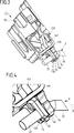
Der der Erfindung zugrunde liegende Gedanke soll nachfolgend anhand der in der Figuren dargestellten Ausführungsbeispiele näher erläutert werden. Es zeigen:The idea underlying the invention will be explained in more detail with reference to the embodiments illustrated in the figures. Show it:
An die Steckplätze
Bei der Klemmeneinrichtung
Bei dem dargestellten Ausführungsbeispiel ergeben sich acht Paare von Steckplätzen
Eine Leitung
Sowohl die Einsteckrichtung E1 für die erste Gehäuseseite
Die Stromschienen
Wie aus
Wie aus
Das Kontaktteil
Dadurch, dass die Endabschnitte
Kommt es im Betrieb der Klemmeneinrichtung
Kommt es zu einer Ausdehnung A längs entlang der Höhenlinie L1–L8 an einer Stromschiene
Wie aus
Der der Erfindung zugrunde liegende Gedanke ist nicht auf die vorangehend geschilderten Ausführungsbeispiele beschränkt, sondern lässt sich grundsätzlich auch bei gänzlich anders gearteten Ausführungsformen verwirklichen. Insbesondere können Stromschienen der hier beschriebenen Art auch bei anderen Klemmeneinrichtungen als Rangierklemmen eingesetzt werden.The idea underlying the invention is not limited to the above-described embodiments, but can in principle be realized even in completely different types of embodiments. In particular, busbars of the type described here can also be used in other terminal devices as jumper terminals.
Der Aufbau einer solchen Klemmeneinrichtung ist nicht notwendigerweise spiegelsymmetrisch. The construction of such a clamping device is not necessarily mirror-symmetrical.
Zudem sind nicht notwendigerweise mehrere Stromschienen vorhanden. Grundsätzlich kann eine Klemmeneinrichtung auch nur eine einzelne Stromschiene mit einem oder mehreren Endabschnitten verwenden. In addition, not necessarily multiple busbars are available. In principle, a clamping device can also use only a single busbar with one or more end sections.
BezugszeichenlisteLIST OF REFERENCE NUMBERS
- 11
- Rangierklemme jumper terminal
- 10, 1110, 11
- Gehäuseseite case side
- 100, 110100, 110
- Steckplatz slot
- 1212
- Gehäuse casing
- 1313
- Kontaktteil contact part
- 130130
- Zapfen spigot
- 131131
- Bügel hanger
- 132132
- Kontaktfeder contact spring
- 133133
- Zwischenraum gap
- 1414
- Halteteil holding part
- 140140
- Zapfen spigot
- 141141
- Halteschenkel holding leg
- 22
- Stromschiene conductor rail
- 2020
- Stromschienenabschnitt Busbar section
- 21, 2221, 22
- Endabschnitt end
- 33
- Leitung management
- 3030
- Leitungsende cable end
- α, βα, β
- Winkel angle
- AA
- Ausdehnungsrichtung extension direction
- E1, E2E1, E2
- Einsteckrichtung insertion
- HH
- Abstand distance
- L1–L8 L1-L8
- Höhenlinie contour
- SS
- Schrägrichtung oblique direction
- XX
- Horizontalrichtung Horizontal direction
- ZZ
- Vertikalrichtung vertical direction
ZITATE ENTHALTEN IN DER BESCHREIBUNG QUOTES INCLUDE IN THE DESCRIPTION
Diese Liste der vom Anmelder aufgeführten Dokumente wurde automatisiert erzeugt und ist ausschließlich zur besseren Information des Lesers aufgenommen. Die Liste ist nicht Bestandteil der deutschen Patent- bzw. Gebrauchsmusteranmeldung. Das DPMA übernimmt keinerlei Haftung für etwaige Fehler oder Auslassungen.This list of the documents listed by the applicant has been generated automatically and is included solely for the better information of the reader. The list is not part of the German patent or utility model application. The DPMA assumes no liability for any errors or omissions.
Zitierte PatentliteraturCited patent literature
- EP 2393160 A1 [0004, 0005, 0008] EP 2393160 A1 [0004, 0005, 0008]
- DE 102007059640 A1 [0004, 0009] DE 102007059640 A1 [0004, 0009]
- WO 2009/052949 A1 [0004] WO 2009/052949 A1 [0004]
- WO 2010/091984 A1 [0004, 0010] WO 2010/091984 A1 [0004, 0010]
Claims (11)
Priority Applications (7)
| Application Number | Priority Date | Filing Date | Title |
|---|---|---|---|
| DE102014115048.1A DE102014115048A1 (en) | 2014-10-16 | 2014-10-16 | Terminal device with a busbar |
| PCT/EP2015/073152 WO2016058889A1 (en) | 2014-10-16 | 2015-10-07 | Terminal device having a busbar |
| EP15778270.7A EP3207594B1 (en) | 2014-10-16 | 2015-10-07 | Terminal device having a busbar |
| CN201580055863.1A CN106797078B (en) | 2014-10-16 | 2015-10-07 | Terminal device with bus bar |
| ES15778270T ES2742437T3 (en) | 2014-10-16 | 2015-10-07 | Terminal device with a conductor rail |
| JP2017537019A JP6408714B2 (en) | 2014-10-16 | 2015-10-07 | Terminal device with busbar |
| US15/518,769 US10044119B2 (en) | 2014-10-16 | 2015-10-07 | Terminal device having a busbar |
Applications Claiming Priority (1)
| Application Number | Priority Date | Filing Date | Title |
|---|---|---|---|
| DE102014115048.1A DE102014115048A1 (en) | 2014-10-16 | 2014-10-16 | Terminal device with a busbar |
Publications (1)
| Publication Number | Publication Date |
|---|---|
| DE102014115048A1 true DE102014115048A1 (en) | 2016-04-21 |
Family
ID=54291284
Family Applications (1)
| Application Number | Title | Priority Date | Filing Date |
|---|---|---|---|
| DE102014115048.1A Ceased DE102014115048A1 (en) | 2014-10-16 | 2014-10-16 | Terminal device with a busbar |
Country Status (7)
| Country | Link |
|---|---|
| US (1) | US10044119B2 (en) |
| EP (1) | EP3207594B1 (en) |
| JP (1) | JP6408714B2 (en) |
| CN (1) | CN106797078B (en) |
| DE (1) | DE102014115048A1 (en) |
| ES (1) | ES2742437T3 (en) |
| WO (1) | WO2016058889A1 (en) |
Families Citing this family (2)
| Publication number | Priority date | Publication date | Assignee | Title |
|---|---|---|---|---|
| DE202015100696U1 (en) * | 2015-02-12 | 2016-05-13 | Weidmüller Interface GmbH & Co. KG | Arrangement of several locking feet for an assembly and assembly |
| JP7501327B2 (en) * | 2020-11-27 | 2024-06-18 | オムロン株式会社 | Terminal block |
Citations (4)
| Publication number | Priority date | Publication date | Assignee | Title |
|---|---|---|---|---|
| WO2009052949A1 (en) | 2007-10-23 | 2009-04-30 | Abb Ag | Terminal block having a connector |
| DE102007059640A1 (en) | 2007-12-10 | 2009-06-18 | Wago Verwaltungsgesellschaft Mbh | connection module |
| WO2010091984A1 (en) | 2009-02-13 | 2010-08-19 | Weidmüller Interface GmbH & Co. KG | Shunting terminal in storied design |
| EP2393160A1 (en) | 2010-06-02 | 2011-12-07 | Weidmüller Interface GmbH & Co. KG | Shunt clamp in a stacked design |
Family Cites Families (22)
| Publication number | Priority date | Publication date | Assignee | Title |
|---|---|---|---|---|
| DE3805158A1 (en) * | 1988-02-15 | 1989-08-24 | Wago Verwaltungs Gmbh | SERIES TERMINAL FOR THE TWO-WIRE POWER SUPPLY OF ELECTRICAL OR ELECTRONIC COMPONENTS, IN PARTICULAR INITIATORS |
| DE3903752A1 (en) * | 1989-02-06 | 1990-08-09 | Wago Verwaltungs Gmbh | PROTECTIVE LADDER TERMINAL |
| DE4203184C3 (en) * | 1992-02-05 | 1996-11-21 | Weidmueller Interface | Protective conductor terminal |
| CH683047A5 (en) * | 1992-02-18 | 1993-12-31 | Woertz Ag | Protective conductor terminal. |
| FR2732518B1 (en) * | 1995-03-29 | 1997-04-30 | Entrelec Sa | CONNECTION ARRANGEMENT FOR ELECTRICAL CONDUCTIVE WIRES AND MODULE, IN PARTICULAR OF THE JUNCTION BLOCK TYPE, EQUIPPED WITH SUCH AN ARRANGEMENT |
| DE19541137A1 (en) * | 1995-10-30 | 1997-05-07 | Wago Verwaltungs Gmbh | Terminal with cut-and-grip contacts for front of insulating housing |
| FR2743448B1 (en) * | 1996-01-10 | 1998-02-13 | Entrelec Sa | INTERCONNECTION ARRANGEMENT FOR ELECTRICAL APPARATUS, IN PARTICULAR FOR TERMINAL BLOCK APPARATUS, AND HOUSING PROVIDED WITH SUCH AN ARRANGEMENT |
| US6146213A (en) * | 1998-12-10 | 2000-11-14 | Yoon; Heung-Sik | Wire connection with exchangeable securing member for electric connection terminal assembly |
| DE29914290U1 (en) * | 1999-08-14 | 2000-12-21 | Weidmüller Interface GmbH & Co, 32760 Detmold | Conductor connection for a clamp that can be placed on a top-hat rail |
| EP1286421B1 (en) * | 2001-08-20 | 2007-12-05 | Woertz Ag | Electrical terminal |
| US7101231B2 (en) * | 2003-10-09 | 2006-09-05 | Cooper Technologies Company | Locking spring-clamp terminal block and method for connecting the same |
| ITMI20061496A1 (en) * | 2006-07-28 | 2008-01-29 | Morsettitalia Spa | TERMINAL WITH U-SHAPED CONDUCTOR FOR THE CONNECTION OF ELECTRIC WIRES |
| EP1953869B1 (en) * | 2007-02-05 | 2014-07-30 | Morsettitalia S.p.A. | Terminal block with jaw part for engagement with the flat pin of movable electric contacts |
| ITMI20071390A1 (en) * | 2007-07-12 | 2009-01-13 | Morsettitalia Spa | TIGHTENING ELEMENT WITH L-SHAPED CONDUCTOR ELEMENT FOR THE CONNECTION OF ELECTRIC WIRES |
| US7413487B1 (en) * | 2007-04-03 | 2008-08-19 | Surtec Industries Inc. | Signal line connector |
| TW200931732A (en) * | 2008-01-04 | 2009-07-16 | Switchlab Inc | Improvement of rail-type grounding terminal structure |
| DE102008014177A1 (en) * | 2008-03-14 | 2009-09-17 | Phoenix Contact Gmbh & Co. Kg | Terminal block and terminal block |
| DE202009013335U1 (en) * | 2009-07-21 | 2010-12-02 | Weidmüller Interface GmbH & Co. KG | Connection device and jumper terminal |
| IT1397530B1 (en) * | 2010-01-20 | 2013-01-16 | Morsettitalia Spa | CONDUCTOR ELEMENT IN SHAPE WITH INTEGRATED MEANS FOR CONTACT / DAMAGE WITH ELECTRICAL DEVICES AND TERMINAL INCLUDING SUCH CONDUCTOR ELEMENT. |
| DE102011054425A1 (en) * | 2011-10-12 | 2013-04-18 | Phoenix Contact Gmbh & Co. Kg | Spring element for spring force clamping assembly, has clamping arm which is formed in U-shape and provided with free end portion that is projected into through opening of support leg |
| US8715017B1 (en) * | 2012-02-08 | 2014-05-06 | Phoenix Contact Development and Manufacturing, Inc. | Terminal block having an extender body fitted to a contact body |
| US20140113502A1 (en) * | 2012-09-28 | 2014-04-24 | Phoenix Contact Development & Manufacturing, Inc. | Connector Block with Spring-Loaded Electrical Terminal Assemblies |
-
2014
- 2014-10-16 DE DE102014115048.1A patent/DE102014115048A1/en not_active Ceased
-
2015
- 2015-10-07 EP EP15778270.7A patent/EP3207594B1/en active Active
- 2015-10-07 US US15/518,769 patent/US10044119B2/en active Active
- 2015-10-07 ES ES15778270T patent/ES2742437T3/en active Active
- 2015-10-07 CN CN201580055863.1A patent/CN106797078B/en active Active
- 2015-10-07 JP JP2017537019A patent/JP6408714B2/en not_active Expired - Fee Related
- 2015-10-07 WO PCT/EP2015/073152 patent/WO2016058889A1/en not_active Ceased
Patent Citations (4)
| Publication number | Priority date | Publication date | Assignee | Title |
|---|---|---|---|---|
| WO2009052949A1 (en) | 2007-10-23 | 2009-04-30 | Abb Ag | Terminal block having a connector |
| DE102007059640A1 (en) | 2007-12-10 | 2009-06-18 | Wago Verwaltungsgesellschaft Mbh | connection module |
| WO2010091984A1 (en) | 2009-02-13 | 2010-08-19 | Weidmüller Interface GmbH & Co. KG | Shunting terminal in storied design |
| EP2393160A1 (en) | 2010-06-02 | 2011-12-07 | Weidmüller Interface GmbH & Co. KG | Shunt clamp in a stacked design |
Also Published As
| Publication number | Publication date |
|---|---|
| US10044119B2 (en) | 2018-08-07 |
| CN106797078A (en) | 2017-05-31 |
| JP2017530540A (en) | 2017-10-12 |
| EP3207594B1 (en) | 2019-06-12 |
| WO2016058889A1 (en) | 2016-04-21 |
| ES2742437T3 (en) | 2020-02-14 |
| EP3207594A1 (en) | 2017-08-23 |
| CN106797078B (en) | 2020-03-13 |
| JP6408714B2 (en) | 2018-10-17 |
| US20170244181A1 (en) | 2017-08-24 |
Similar Documents
| Publication | Publication Date | Title |
|---|---|---|
| EP2053696B1 (en) | Terminal assembly with connectors | |
| EP3342005B1 (en) | Electric terminal block | |
| DE102006014646A1 (en) | Terminal for printed circuit boards | |
| DE202010008933U1 (en) | Electrical connection between two busbars of planar conductors and an insulating layer arranged between the conductors | |
| DE102016116968A1 (en) | Impedance bond | |
| EP2393160B1 (en) | Shunt clamp in a stacked design | |
| DE6928819U (en) | CONNECTOR TO CONNECT THE ENDS OF ELECTRICAL DISTRIBUTION BARS | |
| DE202019005432U1 (en) | Busbar system | |
| EP3109946B1 (en) | Mqs connector | |
| EP3207594B1 (en) | Terminal device having a busbar | |
| DE102007018399B4 (en) | Contacting device of conductor wires with phase selection | |
| DE102012222364A1 (en) | Connector and device with such a connector | |
| DE102014116811A1 (en) | terminal | |
| DE202014009737U1 (en) | Terminal block with a connector | |
| WO2010091984A1 (en) | Shunting terminal in storied design | |
| DE102012015037B4 (en) | electronics module | |
| EP2922146A1 (en) | Device for protecting against excess voltage | |
| DE102008025433A1 (en) | Terminal block for electrical connection of e.g. three-phase alternating current motor, in delta-connection, has plug-in part arranged in housing such that plug-in part is electrically connectable with contacts by connector plugs | |
| DE102017117300A1 (en) | Cross jumper and terminal block arrangement | |
| DE102017127243A1 (en) | honeycomb block | |
| BE1026787B1 (en) | Connection device for electrical conductors | |
| DE202015105021U1 (en) | Connection housing with a connecting device for conductors | |
| DE102014115384A1 (en) | Test cable and socket adapter for a test cable | |
| DE102011121929A1 (en) | Junction box for photovoltaic modules | |
| DE102013003389B4 (en) | Assembly consisting of at least two adjacent electrical connection terminals and a cross connector |
Legal Events
| Date | Code | Title | Description |
|---|---|---|---|
| R012 | Request for examination validly filed | ||
| R002 | Refusal decision in examination/registration proceedings | ||
| R119 | Application deemed withdrawn, or ip right lapsed, due to non-payment of renewal fee | ||
| R003 | Refusal decision now final |