DE102013213051A1 - Conveyor for conveying oil from a reservoir to a transmission of a motor vehicle - Google Patents
Conveyor for conveying oil from a reservoir to a transmission of a motor vehicle Download PDFInfo
- Publication number
- DE102013213051A1 DE102013213051A1 DE102013213051.1A DE102013213051A DE102013213051A1 DE 102013213051 A1 DE102013213051 A1 DE 102013213051A1 DE 102013213051 A DE102013213051 A DE 102013213051A DE 102013213051 A1 DE102013213051 A1 DE 102013213051A1
- Authority
- DE
- Germany
- Prior art keywords
- conveying device
- housing
- cup
- pump
- shaped component
- Prior art date
- Legal status (The legal status is an assumption and is not a legal conclusion. Google has not performed a legal analysis and makes no representation as to the accuracy of the status listed.)
- Ceased
Links
Images


Classifications
-
- F—MECHANICAL ENGINEERING; LIGHTING; HEATING; WEAPONS; BLASTING
- F16—ENGINEERING ELEMENTS AND UNITS; GENERAL MEASURES FOR PRODUCING AND MAINTAINING EFFECTIVE FUNCTIONING OF MACHINES OR INSTALLATIONS; THERMAL INSULATION IN GENERAL
- F16H—GEARING
- F16H57/00—General details of gearing
- F16H57/04—Features relating to lubrication or cooling or heating
- F16H57/0434—Features relating to lubrication or cooling or heating relating to lubrication supply, e.g. pumps; Pressure control
- F16H57/0436—Pumps
-
- F—MECHANICAL ENGINEERING; LIGHTING; HEATING; WEAPONS; BLASTING
- F01—MACHINES OR ENGINES IN GENERAL; ENGINE PLANTS IN GENERAL; STEAM ENGINES
- F01C—ROTARY-PISTON OR OSCILLATING-PISTON MACHINES OR ENGINES
- F01C21/00—Component parts, details or accessories not provided for in groups F01C1/00 - F01C20/00
- F01C21/10—Outer members for co-operation with rotary pistons; Casings
-
- F—MECHANICAL ENGINEERING; LIGHTING; HEATING; WEAPONS; BLASTING
- F04—POSITIVE - DISPLACEMENT MACHINES FOR LIQUIDS; PUMPS FOR LIQUIDS OR ELASTIC FLUIDS
- F04B—POSITIVE-DISPLACEMENT MACHINES FOR LIQUIDS; PUMPS
- F04B17/00—Pumps characterised by combination with, or adaptation to, specific driving engines or motors
- F04B17/06—Mobile combinations
-
- F—MECHANICAL ENGINEERING; LIGHTING; HEATING; WEAPONS; BLASTING
- F04—POSITIVE - DISPLACEMENT MACHINES FOR LIQUIDS; PUMPS FOR LIQUIDS OR ELASTIC FLUIDS
- F04C—ROTARY-PISTON, OR OSCILLATING-PISTON, POSITIVE-DISPLACEMENT MACHINES FOR LIQUIDS; ROTARY-PISTON, OR OSCILLATING-PISTON, POSITIVE-DISPLACEMENT PUMPS
- F04C2/00—Rotary-piston machines or pumps
- F04C2/08—Rotary-piston machines or pumps of intermeshing-engagement type, i.e. with engagement of co-operating members similar to that of toothed gearing
- F04C2/10—Rotary-piston machines or pumps of intermeshing-engagement type, i.e. with engagement of co-operating members similar to that of toothed gearing of internal-axis type with the outer member having more teeth or tooth-equivalents, e.g. rollers, than the inner member
-
- F—MECHANICAL ENGINEERING; LIGHTING; HEATING; WEAPONS; BLASTING
- F04—POSITIVE - DISPLACEMENT MACHINES FOR LIQUIDS; PUMPS FOR LIQUIDS OR ELASTIC FLUIDS
- F04C—ROTARY-PISTON, OR OSCILLATING-PISTON, POSITIVE-DISPLACEMENT MACHINES FOR LIQUIDS; ROTARY-PISTON, OR OSCILLATING-PISTON, POSITIVE-DISPLACEMENT PUMPS
- F04C2/00—Rotary-piston machines or pumps
- F04C2/30—Rotary-piston machines or pumps having the characteristics covered by two or more groups F04C2/02, F04C2/08, F04C2/22, F04C2/24 or having the characteristics covered by one of these groups together with some other type of movement between co-operating members
- F04C2/34—Rotary-piston machines or pumps having the characteristics covered by two or more groups F04C2/02, F04C2/08, F04C2/22, F04C2/24 or having the characteristics covered by one of these groups together with some other type of movement between co-operating members having the movement defined in groups F04C2/08 or F04C2/22 and relative reciprocation between the co-operating members
- F04C2/344—Rotary-piston machines or pumps having the characteristics covered by two or more groups F04C2/02, F04C2/08, F04C2/22, F04C2/24 or having the characteristics covered by one of these groups together with some other type of movement between co-operating members having the movement defined in groups F04C2/08 or F04C2/22 and relative reciprocation between the co-operating members with vanes reciprocating with respect to the inner member
-
- F—MECHANICAL ENGINEERING; LIGHTING; HEATING; WEAPONS; BLASTING
- F04—POSITIVE - DISPLACEMENT MACHINES FOR LIQUIDS; PUMPS FOR LIQUIDS OR ELASTIC FLUIDS
- F04C—ROTARY-PISTON, OR OSCILLATING-PISTON, POSITIVE-DISPLACEMENT MACHINES FOR LIQUIDS; ROTARY-PISTON, OR OSCILLATING-PISTON, POSITIVE-DISPLACEMENT PUMPS
- F04C2240/00—Components
- F04C2240/30—Casings or housings
Landscapes
- Engineering & Computer Science (AREA)
- General Engineering & Computer Science (AREA)
- Mechanical Engineering (AREA)
- Details And Applications Of Rotary Liquid Pumps (AREA)
- Rotary Pumps (AREA)
- Details Of Reciprocating Pumps (AREA)
Abstract
Gegenstand der Erfindung ist eine Fördereinrichtung 1 zur Förderung von Öl aus einem Vorratsbehälter 8 zu einem Getriebe 4 eines Kraftfahrzeuges 12 mit einer wahlweise von einem mechanischen Direktantrieb 9 oder von einem zuschaltbaren Elektroantrieb 10 antreibbaren Ölpumpe 7, wobei die Ölpumpe 7 zwei relativ zueinander bewegliche Bauteile 19, 19a zur Förderung des Öls hat und dass der mechanische Direktantrieb 9 mit einem der relativ zueinander beweglichen Bauteile 19, 19a und der zuschaltbare Elektroantrieb 10 mit dem anderen der relativ zueinander beweglichen Bauteile 19, 19a verbunden ist und dass die relativ zueinander bewegbaren Bauteile 19, 19a in einem Pumpstufengehäuse 20, bestehend aus zwei Steuerscheiben 22, 23 und einem dazwischenliegenden Ring 21, angeordnet sind. Das Pumpstufengehäuse 20 ist in einem topfförmigen Bauteil 40 angeordnet.The invention relates to a delivery device 1 for delivering oil from a reservoir 8 to a transmission 4 of a motor vehicle 12 with an oil pump 7 which can be driven either by a mechanical direct drive 9 or by a switchable electric drive 10, the oil pump 7 having two components 19 which are movable relative to one another , 19a for conveying the oil and that the mechanical direct drive 9 is connected to one of the components 19, 19a that can be moved relative to one another and the switchable electric drive 10 is connected to the other of the components 19, 19a that can be moved relative to one another and that the components 19, 19a are arranged in a pump stage housing 20, consisting of two control disks 22, 23 and an intermediate ring 21. The pump stage housing 20 is arranged in a cup-shaped component 40.
Description
Die Erfindung betrifft eine Fördereinrichtung zur Förderung von Öl aus einem Vorratsbehälter zu einem Getriebe eines Kraftfahrzeuges mit einer wahlweise von einem mechanischen Direktantrieb oder von einem zuschaltbaren Elektroantrieb antreibbaren Ölpumpe, welche zwei relativ zueinander bewegliche Bauteile zur Förderung des Öls hat, dass der mechanische Direktantrieb mit einem der relativ zueinander beweglichen Bauteile und der zuschaltbare Elektroantrieb mit dem anderen der relativ zueinander beweglichen Bauteile verbunden ist, und dass die relativ zueinander bewegbaren Bauteile in einem Pumpstufengehäuse, bestehend aus zwei Steuerscheiben und einem dazwischenliegenden Ring, angeordnet sind. The invention relates to a conveyor for conveying oil from a reservoir to a transmission of a motor vehicle with an optionally driven by a mechanical direct drive or by a switchable electric drive oil pump, which has two relatively movable components for conveying the oil that the mechanical direct drive with a the relatively movable components and the switchable electric drive is connected to the other of the relatively movable components, and that the relatively movable components are arranged in a pump stage housing consisting of two control discs and an intermediate ring.
Solche Fördereinrichtungen werden insbesondere bei Kraftfahrzeugen mit Hybridantrieb eingesetzt. Bei solchen Hybridantrieben wird die Ölpumpe zur Versorgung eines Getriebes direkt von dem Getriebe angetrieben. Bei Stillstand des Getriebes soll dessen Funktion aufrechterhalten werden und daher die Ölpumpe in Betrieb bleiben. Such conveyors are used in particular in motor vehicles with hybrid drive. In such hybrid drives, the oil pump is driven to supply a transmission directly from the transmission. At standstill of the transmission whose function should be maintained and therefore the oil pump remain in operation.
Aus der
Der Erfindung liegt die Aufgabe zugrunde, eine Fördereinrichtung der eingangs genannten Art so weiterzubilden, dass sie einen geringeren Bauraum bei besserem Wirkungsgrad besitzt. The invention has the object of providing a conveyor of the type mentioned in such a way that it has a smaller space with better efficiency.
Die Aufgabe wird erfindungsgemäß dadurch gelöst, dass das Pumpstufengehäuse in einem topfförmigen Bauteil angeordnet ist. The object is achieved in that the pumping stage housing is arranged in a pot-shaped component.
Mit dem Vorsehen eines topfförmigen Bauteils zur Aufnahme des Pumpstufengehäuses ist das topfförmige Bauteil das Bauteil, welches für die Anordnung in dem Gehäuse der Ölpumpe anzupassen ist. Dadurch kann das Pumpstufengehäuse durch die Verwendung herkömmlicher Bauteile einfacher ausgestaltet sein. Die Fördereinrichtung ist dadurch kostengünstiger. Weiter ermöglicht das topfförmige Bauteil eine einfachere Anordnung und Befestigung des Pumpstufengehäuses, so dass das Pumpstufengehäuse und damit die Ölpumpe geringere radiale Abmessungen aufweist und dadurch weniger Bauraum beansprucht. Aufgrund der geringeren Abmessungen können Lager und Dichtungen mit geringerem Durchmesser zum Einsatz kommen, so dass infolge geringerer Reibwerte der Wirkungsgrad steigt. Schließlich bewirkt das topfförmige Gehäuse, dass die Außenseite der auslassseitigen Steuerscheibe mit dem erzeugten Druck beaufschlagt wird, was eine Verringerung des Axialspalts der Pumpstufe bewirkt und ebenfalls zu einer Erhöhung des Wirkungsgrades führt. With the provision of a pot-shaped component for receiving the pump stage housing, the pot-shaped component is the component which is to be adapted for the arrangement in the housing of the oil pump. As a result, the pump stage housing can be made simpler by the use of conventional components. The conveyor is thereby cheaper. Next, the pot-shaped component allows a simpler arrangement and attachment of the pump stage housing, so that the pump stage housing and thus the oil pump has smaller radial dimensions and thereby requires less space. Due to the smaller dimensions, bearings and seals with a smaller diameter can be used so that the efficiency increases as a result of lower coefficients of friction. Finally, the pot-shaped housing causes the outside of the outlet-side control disc is subjected to the generated pressure, which causes a reduction of the axial gap of the pumping stage and also leads to an increase in the efficiency.
Eine einfache Befestigung des Pumpstufengehäuses ist gegeben, wenn diese axial in dem topfförmigen Bauteil eingespannt ist. A simple attachment of the pump stage housing is given if it is clamped axially in the cup-shaped component.
In vorteilhafter Weise erfolgt eine derartige Befestigung mittels eines Sprengrings, der auf der Innenseite des topfförmigen Bauteils eingesetzt ist, und so das Pumpstufengehäuse axial eingespannt. Advantageously, such attachment by means of a snap ring, which is inserted on the inside of the cup-shaped member, and so axially clamped the pump stage housing.
Ein zusätzliches Sicherungselement zum Einspannen wird gemäß einer anderen Ausgestaltung dadurch vermieden, dass die offenen Seite des topfförmigen Bauteils zum axialen Einspannen des Pumpstufengehäuses gebördelt oder verstemmt ist. An additional securing element for clamping is avoided according to another embodiment in that the open side of the pot-shaped component is crimped or caulked for axial clamping of the pump stage housing.
Zur Beaufschlagung der Außenseite der auslassseitigen Steuerscheibe mit dem erzeugten Druck kann der Boden des topfförmigen Bauteils entsprechende Formelemente wie Absätze oder nach innen gerichtete Rillen aufweisen, die einen Abstand zwischen Boden und Pumpstufengehäuse erzeugen. Eine derartige Formgestaltung des Bodens wird vermieden, wenn das Pumpstufengehäuse mit einem Dichtring gegen den Boden des topfförmigen Gehäuses axial eingespannt ist. Diese Ausgestaltung hat zudem den Vorteil, dass über den Dichtring ein Toleranzausgleich erfolgt. To act on the outside of the outlet-side control disk with the pressure generated, the bottom of the cup-shaped component may have corresponding form elements such as shoulders or inwardly directed grooves which produce a distance between the bottom and pump stage housing. Such a design of the bottom is avoided when the pump stage housing is clamped axially with a sealing ring against the bottom of the cup-shaped housing. This embodiment also has the advantage that tolerance compensation takes place via the sealing ring.
Die Zuführung des anzusaugenden Öls vom Einlass der Ölpumpe zu der Pumpstufe erfolgt in einfacher Weise dadurch, dass in der Mantelfläche des topfförmigen Bauteils Öffnungen angeordnet sind, die mit den Einlasskanälen der Pumpstufe in Verbindung stehen. The feeding of the oil to be sucked from the inlet of the oil pump to the pumping stage is effected in a simple manner by arranging openings in the jacket surface of the cup-shaped component, which are in communication with the inlet ports of the pumping stage.
Die Verdrehsicherheit des Pumpstufengehäuses mit dem topfförmigen Bauteil lässt sich weiter dadurch erhöhen, wenn an der Mantelfläche des topfförmigen Bauteils Laschen zum Eingriff in das Pumpstufengehäuse angeordnet sind. Separate Aufnahmen im Pumpstufengehäuse für die Laschen werden in einer vorteilhaften Ausgestaltung dadurch vermieden, dass die Laschen in die Kanäle des Pumpstufengehäuses eingreifen. The security against rotation of the pump stage housing with the cup-shaped component can be further increased if lugs are arranged for engagement in the pump stage housing on the lateral surface of the pot-shaped component. Separate recordings in the pump stage housing for the tabs are avoided in an advantageous embodiment in that the tabs engage in the channels of the pump stage housing.
In einer weiteren Ausgestaltung geht der Boden des topfförmigen Bauteils in eine Hohlwelle über, deren Durchmesser kleiner als die Mantelfläche des topfförmigen Bauteils ist. Über die Hohlwelle lässt sich das topfförmige Bauteil im Gehäuse lagern, wobei infolge des geringen Durchmessers kein zusätzlicher Bauraum in radialer Richtung erforderlich ist. Die geringen Abmessungen wirken sich zudem vorteilhaft auf Gewicht und Wirkungsgrad der Ölpumpe aus. In a further embodiment, the bottom of the pot-shaped component passes into a hollow shaft whose diameter is smaller than the lateral surface of the pot-shaped component. About the hollow shaft, the cup-shaped component can be stored in the housing, with no additional space in the radial direction is required due to the small diameter. The small dimensions also have an advantageous effect on the weight and efficiency of the oil pump.
Ein besonders einfaches Ableiten des geförderten Öls zum Auslass im Gehäuse wird dadurch erreicht, dass die Hohlwelle radial angeordnete Öffnungen besitzt. A particularly simple derivation of the pumped oil to the outlet in the housing is achieved in that the hollow shaft has radially arranged openings.
Zur Förderung des Öls hat die Ölpumpe zwei relativ zueinander bewegliche Bauteile, wobei der mechanische Direktantrieb mit einem der relativ zueinander beweglichen Bauteile und der zuschaltbare Elektroantrieb mit dem anderen der relativ zueinander beweglichen Bauteile verbunden ist. To promote the oil, the oil pump has two relatively movable components, wherein the mechanical direct drive is connected to one of the relatively movable components and the switchable electric drive with the other of the relatively movable components.
Die erfindungsgemäße Fördereinrichtung ermöglicht auch einen Parallelbetrieb des Direktantriebs und des Elektroantriebs, wenn beispielsweise der Elektroantrieb frühzeitig gestartet werden soll, bevor der Direktantrieb abgeschaltet wird. Ebenso kann die Förderleistung der Ölpumpe durch Zuschaltung des Elektroantriebs angehoben werden, wenn der Direktantrieb bei einem Betriebszustand mit zu geringer Drehzahl läuft. The conveyor according to the invention also allows a parallel operation of the direct drive and the electric drive, for example, if the electric drive should be started early, before the direct drive is turned off. Likewise, the delivery of the oil pump can be increased by switching the electric drive when the direct drive runs in an operating condition with too low speed.
Die Ölpumpe gestaltet sich gemäß einer anderen vorteilhaften Weiterbildung der Erfindung konstruktiv besonders einfach, wenn das topfförmige Bauteil gegenüber einem feststehenden Gehäuse der Ölpumpe drehbar gelagert und mittels einer Radialdichtung abgedichtet ist, und wenn Einlass- und Auslassanschlüsse zum hydraulischen Anschluss der Ölpumpe an dem Gehäuse angeordnet sind. According to another advantageous development of the invention, the oil pump is structurally particularly simple if the cup-shaped component is rotatably mounted relative to a stationary housing of the oil pump and sealed by means of a radial seal, and if inlet and outlet connections are arranged on the housing for the hydraulic connection of the oil pump ,
Die erfindungsgemäße Fördereinrichtung gestaltet sich besonders kompakt, wenn das Gehäuse eine gemeinsame Ausnehmung für einen Elektromotor des Elektroantriebs und das topfförmige Bauteil hat. Dadurch wird der Elektromotor von dem geförderten Öl gekühlt und dessen Geräusche gedämpft. Weiterhin kann hierdurch die Abdichtung einer Wellendurchführung für den Elektroantrieb entfallen. The conveyor according to the invention is particularly compact, when the housing has a common recess for an electric motor of the electric drive and the cup-shaped component. As a result, the electric motor is cooled by the extracted oil and its noise is damped. Furthermore, this eliminates the sealing of a shaft passage for the electric drive.
Eine Beeinflussung des Elektroantriebs durch chemische oder physikalische Einflüsse des Öls lässt sich gemäß einer anderen vorteilhaften Weiterbildung der Erfindung einfach vermeiden, wenn das Gehäuse eine erste Ausnehmung für das Läuferteil und den Rotor der Ölpumpe und eine zweite Ausnehmung für den Elektromotor des Elektroantriebs hat. An influence of the electric drive by chemical or physical influences of the oil can be according to another advantageous embodiment of the invention easily avoided if the housing has a first recess for the rotor part and the rotor of the oil pump and a second recess for the electric motor of the electric drive.
Ein vorgesehenes Antriebsmoment beim Betrieb der Ölpumpe durch den Elektroantrieb lässt sich gemäß einer anderen vorteilhaften Weiterbildung der Erfindung einfach einstellen, wenn der Elektroantrieb ein Untersetzungsgetriebe hat. A proposed drive torque during operation of the oil pump by the electric drive can be easily adjusted according to another advantageous embodiment of the invention, when the electric drive has a reduction gear.
Das topfförmige Bauteil könnte beispielsweise einen umlaufenden Zahnkranz an der Mantelfläche aufweisen, an dem der jeweilige Antrieb angelenkt ist. Dies führt jedoch zu großen Abmessungen und damit zu einem erhöhten baulichen Aufwand der Ölpumpe. Die Ölpumpe gestaltet sich gemäß einer anderen vorteilhaften Weiterbildung der Erfindung besonders kompakt, wenn der Rotor auf einer Welle des einen Antriebs befestigt ist und das topfförmige Bauteil im Bereich der am Boden angeformten Hohlwelle mit dem anderen Antrieb verbunden ist. Selbstverständlich können in kinematischer Umkehr die Antriebe auch mit dem jeweilig anderen Teil verbunden sein. Vorzugsweise ist die Hohlwelle ausschließlich innerhalb des Gehäuses geführt, so dass die Abdichtung einer Wellendurchführung vermieden wird. The pot-shaped component could, for example, have a circumferential sprocket on the lateral surface, on which the respective drive is articulated. However, this leads to large dimensions and thus to increased structural complexity of the oil pump. The oil pump is particularly compact according to another advantageous embodiment of the invention, when the rotor is mounted on a shaft of a drive and the cup-shaped member is connected in the region of the integrally formed on the bottom of the hollow shaft with the other drive. Of course, the drives can also be connected to the respective other part in kinematic reversal. Preferably, the hollow shaft is guided exclusively within the housing, so that the sealing of a shaft bushing is avoided.
Die Ölpumpe besteht gemäß einer anderen vorteilhaften Weiterbildung der Erfindung aus besonders wenigen zu montierenden Bauteilen, wenn der Ring oder die Steuerplatten die Ölzufuhrelemente aufweisen. According to another advantageous development of the invention, the oil pump consists of particularly few components to be mounted when the ring or the control plates have the oil supply elements.
Eine gegenseitige Beeinflussung der Antriebe untereinander lässt sich gemäß einer anderen vorteilhaften Weiterbildung der Erfindung einfach vermeiden, wenn der Direktantrieb und der Elektroantrieb selbsthemmend gestaltet sind. A mutual influence of the drives with each other can be easily avoided according to another advantageous embodiment of the invention, when the direct drive and the electric drive are designed to be self-locking.
Die Ölpumpe lässt sich gemäß einer anderen vorteilhaften Weiterbildung der Erfindung besonders vorteilhaft von zwei unterschiedlichen Antrieben antreiben, wenn die Ölpumpe als Zahnringpumpe, als Flügelzellenpumpe oder als Außenzahnradpumpe ausgebildet ist. Bei solchen Pumpprinzipien wirken der entsprechend gestaltete Rotor und ein den Rotor umgebender Ring derart zusammen, dass auf besonders einfache Art wahlweise der Ring oder der Rotor zur Förderung des Öls angetrieben werden kann. According to another advantageous development of the invention, the oil pump can be driven particularly advantageously by two different drives when the oil pump is designed as a toothed ring pump, as a vane cell pump or as an external gear pump. In such pumping principles, the correspondingly shaped rotor and a ring surrounding the rotor cooperate in such a way that, in a particularly simple manner, either the ring or the ring Rotor can be driven to promote the oil.
Die Erfindung lässt zahlreiche Ausführungsformen zu. Zur weiteren Verdeutlichung ihres Grundprinzips sind mehrere davon in der Zeichnung dargestellt und werden nachfolgend beschrieben. Diese zeigt in: The invention allows numerous embodiments. To further clarify its basic principle, several of them are shown in the drawing and will be described below. This shows in:
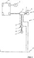
Das Getriebe
Dreht man die Welle
Die Verbindung der Fördereinrichtung
ZITATE ENTHALTEN IN DER BESCHREIBUNG QUOTES INCLUDE IN THE DESCRIPTION
Diese Liste der vom Anmelder aufgeführten Dokumente wurde automatisiert erzeugt und ist ausschließlich zur besseren Information des Lesers aufgenommen. Die Liste ist nicht Bestandteil der deutschen Patent- bzw. Gebrauchsmusteranmeldung. Das DPMA übernimmt keinerlei Haftung für etwaige Fehler oder Auslassungen.This list of the documents listed by the applicant has been generated automatically and is included solely for the better information of the reader. The list is not part of the German patent or utility model application. The DPMA assumes no liability for any errors or omissions.
Zitierte PatentliteraturCited patent literature
- DE 102011084542 A1 [0003] DE 102011084542 A1 [0003]
Claims (19)
Priority Applications (7)
| Application Number | Priority Date | Filing Date | Title |
|---|---|---|---|
| DE102013213051.1A DE102013213051A1 (en) | 2013-06-18 | 2013-07-04 | Conveyor for conveying oil from a reservoir to a transmission of a motor vehicle |
| CN201480034521.7A CN105339588B (en) | 2013-06-18 | 2014-05-28 | Delivery device for delivering oil from a storage container to a motor vehicle transmission |
| EP14727464.1A EP3011138A1 (en) | 2013-06-18 | 2014-05-28 | Pumping device for pumping oil from a reservoir to a transmission of a motor vehicle |
| US14/899,488 US9797501B2 (en) | 2013-06-18 | 2014-05-28 | Delivery device for delivering oil from a reservoir to a transmission of a motor vehicle |
| KR1020167001302A KR20160021450A (en) | 2013-06-18 | 2014-05-28 | Pumping device for pumping oil from a reservoir to a transmission of a motor vehicle |
| PCT/EP2014/061071 WO2014202366A1 (en) | 2013-06-18 | 2014-05-28 | Pumping device for pumping oil from a reservoir to a transmission of a motor vehicle |
| JP2016520351A JP6223561B2 (en) | 2013-06-18 | 2014-05-28 | Pumping device that pumps oil from the storage container to the transmission of the car |
Applications Claiming Priority (3)
| Application Number | Priority Date | Filing Date | Title |
|---|---|---|---|
| DE102013211428.1 | 2013-06-18 | ||
| DE102013211428 | 2013-06-18 | ||
| DE102013213051.1A DE102013213051A1 (en) | 2013-06-18 | 2013-07-04 | Conveyor for conveying oil from a reservoir to a transmission of a motor vehicle |
Publications (1)
| Publication Number | Publication Date |
|---|---|
| DE102013213051A1 true DE102013213051A1 (en) | 2014-12-18 |
Family
ID=52009830
Family Applications (1)
| Application Number | Title | Priority Date | Filing Date |
|---|---|---|---|
| DE102013213051.1A Ceased DE102013213051A1 (en) | 2013-06-18 | 2013-07-04 | Conveyor for conveying oil from a reservoir to a transmission of a motor vehicle |
Country Status (7)
| Country | Link |
|---|---|
| US (1) | US9797501B2 (en) |
| EP (1) | EP3011138A1 (en) |
| JP (1) | JP6223561B2 (en) |
| KR (1) | KR20160021450A (en) |
| CN (1) | CN105339588B (en) |
| DE (1) | DE102013213051A1 (en) |
| WO (1) | WO2014202366A1 (en) |
Cited By (3)
| Publication number | Priority date | Publication date | Assignee | Title |
|---|---|---|---|---|
| DE102015221891A1 (en) * | 2015-11-06 | 2017-05-11 | Continental Automotive Gmbh | Conveying device for conveying oil |
| DE102015221901A1 (en) * | 2015-11-06 | 2017-05-11 | Continental Automotive Gmbh | Conveying device for conveying oil from an oil sump to a lubricating oil circuit |
| KR20180059924A (en) * | 2015-10-13 | 2018-06-05 | 콘티넨탈 오토모티브 게엠베하 | Automotive Emission Device |
Families Citing this family (4)
| Publication number | Priority date | Publication date | Assignee | Title |
|---|---|---|---|---|
| EP3594505B1 (en) | 2018-07-11 | 2023-12-13 | Vitesco Technologies GmbH | Pump device |
| US11624363B2 (en) | 2020-05-15 | 2023-04-11 | Hanon Systems EFP Canada Ltd. | Dual drive gerotor pump |
| US11473575B2 (en) | 2020-05-15 | 2022-10-18 | Hanon Systems EFP Canada Ltd. | Dual drive vane pump |
| DE102022109970A1 (en) * | 2022-04-26 | 2023-10-26 | Audi Aktiengesellschaft | Geared motor for a motor vehicle and motor vehicle with a geared motor |
Citations (3)
| Publication number | Priority date | Publication date | Assignee | Title |
|---|---|---|---|---|
| DE19750675C1 (en) * | 1997-11-15 | 1998-08-13 | Zahnradfabrik Friedrichshafen | Oil pump for automatic transmission of vehicle engine |
| DE102004005430A1 (en) * | 2004-02-04 | 2005-08-25 | Zf Friedrichshafen Ag | Oil pump for automatic motor vehicle transmission |
| DE102011084542A1 (en) | 2011-10-14 | 2013-04-18 | Continental Automotive Gmbh | Conveyor for conveying oil from a reservoir to a transmission of a motor vehicle |
Family Cites Families (9)
| Publication number | Priority date | Publication date | Assignee | Title |
|---|---|---|---|---|
| JP3343660B2 (en) * | 1992-12-10 | 2002-11-11 | 本田技研工業株式会社 | Oil pump drive |
| ATE377710T1 (en) * | 2003-05-26 | 2007-11-15 | Ixetic Hueckeswagen Gmbh | VANE PUMP WITH DEEP-DRAWN STEEL POT |
| DE112004001622D2 (en) * | 2003-06-30 | 2006-05-11 | Luk Automobiltech Gmbh & Co Kg | In a combustion engine integrated pump |
| US20100047088A1 (en) * | 2008-08-20 | 2010-02-25 | Protonex Technology Corporation | Roller vane pump with integrated motor |
| DE102008054767A1 (en) * | 2008-12-16 | 2010-06-17 | Robert Bosch Gmbh | Conveying device, particularly gear wheel pump, has housing, with two housing units, where conveyor elements are formed as gear wheels and are inserted between two housing units |
| JP5654374B2 (en) * | 2011-02-02 | 2015-01-14 | トーヨーエイテック株式会社 | Oil pump drive control device |
| EP2691651A2 (en) * | 2011-03-31 | 2014-02-05 | ixetic Bad Homburg GmbH | Drive unit for a submerged oil pump and pump |
| WO2013007247A1 (en) * | 2011-07-08 | 2013-01-17 | Ixetic Bad Homburg Gmbh | Pump drive |
| DE102013212106B4 (en) * | 2013-06-25 | 2015-10-08 | Continental Automotive Gmbh | Method for correcting a first time of a motor vehicle and arrangement for a motor vehicle |
-
2013
- 2013-07-04 DE DE102013213051.1A patent/DE102013213051A1/en not_active Ceased
-
2014
- 2014-05-28 US US14/899,488 patent/US9797501B2/en active Active
- 2014-05-28 KR KR1020167001302A patent/KR20160021450A/en not_active Ceased
- 2014-05-28 WO PCT/EP2014/061071 patent/WO2014202366A1/en not_active Ceased
- 2014-05-28 EP EP14727464.1A patent/EP3011138A1/en not_active Withdrawn
- 2014-05-28 CN CN201480034521.7A patent/CN105339588B/en active Active
- 2014-05-28 JP JP2016520351A patent/JP6223561B2/en active Active
Patent Citations (3)
| Publication number | Priority date | Publication date | Assignee | Title |
|---|---|---|---|---|
| DE19750675C1 (en) * | 1997-11-15 | 1998-08-13 | Zahnradfabrik Friedrichshafen | Oil pump for automatic transmission of vehicle engine |
| DE102004005430A1 (en) * | 2004-02-04 | 2005-08-25 | Zf Friedrichshafen Ag | Oil pump for automatic motor vehicle transmission |
| DE102011084542A1 (en) | 2011-10-14 | 2013-04-18 | Continental Automotive Gmbh | Conveyor for conveying oil from a reservoir to a transmission of a motor vehicle |
Cited By (9)
| Publication number | Priority date | Publication date | Assignee | Title |
|---|---|---|---|---|
| KR20180059924A (en) * | 2015-10-13 | 2018-06-05 | 콘티넨탈 오토모티브 게엠베하 | Automotive Emission Device |
| CN108138612A (en) * | 2015-10-13 | 2018-06-08 | 大陆汽车有限责任公司 | Conveyors for motor vehicles |
| JP2018533687A (en) * | 2015-10-13 | 2018-11-15 | コンチネンタル オートモーティヴ ゲゼルシャフト ミット ベシュレンクテル ハフツングContinental Automotive GmbH | Pumping equipment for automobiles |
| US10634235B2 (en) | 2015-10-13 | 2020-04-28 | Continental Automotive Gmbh | Delivery device for a motor vehicle |
| KR102144204B1 (en) * | 2015-10-13 | 2020-08-12 | 콘티넨탈 오토모티브 게엠베하 | Automotive emission device |
| DE102015221891A1 (en) * | 2015-11-06 | 2017-05-11 | Continental Automotive Gmbh | Conveying device for conveying oil |
| WO2017076975A1 (en) * | 2015-11-06 | 2017-05-11 | Continental Automotive Gmbh | Conveying device for conveying oil |
| DE102015221901A1 (en) * | 2015-11-06 | 2017-05-11 | Continental Automotive Gmbh | Conveying device for conveying oil from an oil sump to a lubricating oil circuit |
| US11078815B2 (en) | 2015-11-06 | 2021-08-03 | Vitesco Technologies GmbH | Conveying device for conveying oil |
Also Published As
| Publication number | Publication date |
|---|---|
| EP3011138A1 (en) | 2016-04-27 |
| JP6223561B2 (en) | 2017-11-01 |
| KR20160021450A (en) | 2016-02-25 |
| US9797501B2 (en) | 2017-10-24 |
| US20160146331A1 (en) | 2016-05-26 |
| CN105339588A (en) | 2016-02-17 |
| JP2016522353A (en) | 2016-07-28 |
| WO2014202366A1 (en) | 2014-12-24 |
| CN105339588B (en) | 2018-04-27 |
Similar Documents
| Publication | Publication Date | Title |
|---|---|---|
| EP3516249B1 (en) | Multi-clutch device and hybrid module for a motor vehicle | |
| DE102013213051A1 (en) | Conveyor for conveying oil from a reservoir to a transmission of a motor vehicle | |
| EP3322606B2 (en) | Hybrid module | |
| EP2766638B1 (en) | Pumping device for pumping oil from a storage container to a transmission system of a motor vehicle | |
| DE102014101713A1 (en) | Electric portal axle for the electric drive of a motor vehicle | |
| DE102014216323B4 (en) | Hybrid module with improved clutch actuation and more flexible installation options | |
| DE102013012815A1 (en) | Dual clutch device for arrangement in powertrain of motor car, has clutch supporting hub structure that is provided with hub portions, and transmission input shaft which is connected with coupling assembly | |
| DE102016121241A1 (en) | Hydraulic drive, hydraulic motor and integrated pump with hydraulic drive | |
| DE102013219326A1 (en) | Coupling device, and hybrid drive unit or transmission with such a coupling device | |
| DE102010054250A1 (en) | hydraulic control | |
| DE102019001957C5 (en) | Hybrid drive system | |
| DE102015218748A1 (en) | Hybrid drive module for a motor vehicle | |
| EP3759371B1 (en) | Clutch assembly and drive unit having this clutch assembly | |
| DE102015211477A1 (en) | Hydrostatic clutch actuator | |
| DE102016224898A1 (en) | Pumping device for an automatic transmission | |
| EP3826873B1 (en) | Hybrid module comprising a input shaft having a rotary union, and actuation unit for one of multiple clutches, and drive train | |
| DE102017211809A1 (en) | Drive unit for a motor vehicle with an electric machine and a clutch | |
| EP2882976A1 (en) | Pumping device | |
| DE102016201869A1 (en) | Coupling arrangement for the drive train of a vehicle | |
| DE102014214049A1 (en) | Turbomachine with centrifugal seal | |
| DE102015112664B4 (en) | Annular gear pump | |
| DE19948344B4 (en) | Hydrostatic slewing drive | |
| DE102006027773A1 (en) | Vehicle brake piston pump | |
| WO2022122858A1 (en) | Pump device for a hydraulic system of a motor vehicle, hydraulic system | |
| DE102021125200A1 (en) | Drive device for a motor vehicle with an operating medium tank formed in a machine housing |
Legal Events
| Date | Code | Title | Description |
|---|---|---|---|
| R012 | Request for examination validly filed | ||
| R002 | Refusal decision in examination/registration proceedings | ||
| R003 | Refusal decision now final |