DE102013113863A1 - Vertical axle wind-power plant, has rotatable carrier arranged opposite to wings over axles, and positioning device provided with sensor and servomotor that are formed to rotate carrier such that wing is vertically aligned in wind direction - Google Patents

Vertical axle wind-power plant, has rotatable carrier arranged opposite to wings over axles, and positioning device provided with sensor and servomotor that are formed to rotate carrier such that wing is vertically aligned in wind direction Download PDF

Info

Publication number
DE102013113863A1
DE102013113863A1 DE102013113863.2A DE102013113863A DE102013113863A1 DE 102013113863 A1 DE102013113863 A1 DE 102013113863A1 DE 102013113863 A DE102013113863 A DE 102013113863A DE 102013113863 A1 DE102013113863 A1 DE 102013113863A1
Authority
DE
Germany
Prior art keywords
wing
carrier
wings
vertical axis
wind
Prior art date
Legal status (The legal status is an assumption and is not a legal conclusion. Google has not performed a legal analysis and makes no representation as to the accuracy of the status listed.)
Withdrawn
Application number
DE102013113863.2A
Other languages
German (de)
Inventor
Jakob Hölzel
Current Assignee (The listed assignees may be inaccurate. Google has not performed a legal analysis and makes no representation or warranty as to the accuracy of the list.)
Individual
Original Assignee
Individual
Priority date (The priority date is an assumption and is not a legal conclusion. Google has not performed a legal analysis and makes no representation as to the accuracy of the date listed.)
Filing date
Publication date
Application filed by Individual filed Critical Individual
Priority to DE102013113863.2A priority Critical patent/DE102013113863A1/en
Publication of DE102013113863A1 publication Critical patent/DE102013113863A1/en
Withdrawn legal-status Critical Current

Links

Images

Classifications

    • FMECHANICAL ENGINEERING; LIGHTING; HEATING; WEAPONS; BLASTING
    • F03MACHINES OR ENGINES FOR LIQUIDS; WIND, SPRING, OR WEIGHT MOTORS; PRODUCING MECHANICAL POWER OR A REACTIVE PROPULSIVE THRUST, NOT OTHERWISE PROVIDED FOR
    • F03DWIND MOTORS
    • F03D3/00Wind motors with rotation axis substantially perpendicular to the air flow entering the rotor 
    • F03D3/06Rotors
    • F03D3/062Rotors characterised by their construction elements
    • F03D3/066Rotors characterised by their construction elements the wind engaging parts being movable relative to the rotor
    • F03D3/067Cyclic movements
    • F03D3/068Cyclic movements mechanically controlled by the rotor structure
    • YGENERAL TAGGING OF NEW TECHNOLOGICAL DEVELOPMENTS; GENERAL TAGGING OF CROSS-SECTIONAL TECHNOLOGIES SPANNING OVER SEVERAL SECTIONS OF THE IPC; TECHNICAL SUBJECTS COVERED BY FORMER USPC CROSS-REFERENCE ART COLLECTIONS [XRACs] AND DIGESTS
    • Y02TECHNOLOGIES OR APPLICATIONS FOR MITIGATION OR ADAPTATION AGAINST CLIMATE CHANGE
    • Y02EREDUCTION OF GREENHOUSE GAS [GHG] EMISSIONS, RELATED TO ENERGY GENERATION, TRANSMISSION OR DISTRIBUTION
    • Y02E10/00Energy generation through renewable energy sources
    • Y02E10/70Wind energy
    • Y02E10/74Wind turbines with rotation axis perpendicular to the wind direction

Landscapes

  • Engineering & Computer Science (AREA)
  • Life Sciences & Earth Sciences (AREA)
  • Sustainable Development (AREA)
  • Sustainable Energy (AREA)
  • Chemical & Material Sciences (AREA)
  • Combustion & Propulsion (AREA)
  • Mechanical Engineering (AREA)
  • General Engineering & Computer Science (AREA)
  • Wind Motors (AREA)

Abstract

The plant has a rotatable carrier (2) arranged opposite to wings (10-40) over vertical axles (3). The wings are coupled and rotatable around vertical axles (11, 21, 31, 41) such that the carrier takes place with full revolution of the carrier with the half revolution of the wings. The wing areas (12, 22, 32, 42) are arranged opposite to the wings and orthogonally aligned to each other. A positioning device is provided with a wind sensor and a servomotor that are formed to rotate the carrier such that the wing is vertically aligned to a wind direction (4).

Description

Gebiet der ErfindungField of the invention

Die Erfindung betrifft eine Vertikalachswindkraftanlage mit mindestens einem um die vertikale Achse drehbaren Träger und mindestens zwei an dem Träger sich jeweils gegenüber angeordneten Flügeln.The invention relates to a Vertikalachswindkraftanlage with at least one rotatable about the vertical axis carrier and at least two on the carrier in each case opposite arranged wings.

Hintergrund der ErfindungBackground of the invention

Windkraftanlagen ernten mit ihrem Rotor die Energie des Windes, wandeln sie in elektrische Energie um und speisen sie in das Stromnetz ein. Üblich sind Windkraftanlagen mit einem sternförmigen Rotor und meist drei Blättern, welche vor einem Mast oder Turm um eine horizontale Achse rotieren. Hingegen haben sich die Windkraftanlagen mit vertikaler Achse nicht durchgesetzt.Wind turbines harvest the energy of the wind with their rotor, convert it into electrical energy and feed it into the power grid. Common are wind turbines with a star-shaped rotor and usually three leaves, which rotate about a horizontal axis in front of a mast or tower. By contrast, wind turbines with a vertical axis have not prevailed.

Zusammenfassung der ErfindungSummary of the invention

Die vorliegende Erfindung wurde vor dem Hintergrund des vorstehend beschriebenen Stands der Technik entwickelt. Aufgabe der Erfindung ist es daher, eine neue Bauform einer Vertikalachswindkraftanlage vorzuschlagen, die einen verbesserten Wirkungsgrad aufweist.The present invention has been developed in light of the above-described prior art. The object of the invention is therefore to propose a new design of a Vertikalachswindkraftanlage having improved efficiency.

Diese Aufgabe wird dadurch gelöst, dass die Flügel jeweils um ihre vertikale Achse drehbar und mit dem Träger derart gekoppelt sind, dass bei einer vollen Umdrehung des Trägers jeweils eine halbe Umdrehung der Flügel erfolgt, wobei in jeder Drehstellung des Trägers die Flügelflächen der sich jeweils gegenüber angeordneten Flügel im Wesentlichen orthogonal zueinander ausgerichtet sind oder zumindest die von den Flügelflächen aufgespannten Ebenen im Wesentlichen orthogonal zueinander ausgerichtet sind.This object is achieved in that the wings are each rotatable about their vertical axis and coupled to the carrier in such a way that in a full rotation of the carrier in each case half a turn of the wings, wherein in each rotational position of the carrier, the wing surfaces of each opposite arranged wings are aligned substantially orthogonal to each other or at least the planes spanned by the wing surfaces are aligned substantially orthogonal to each other.

Vorteilhafte Ausgestaltungen der Erfindung mit zusätzlichen Merkmalen werden nachfolgend beschrieben.Advantageous embodiments of the invention with additional features will be described below.

In einer bevorzugten Ausführungsform sind vier Flügel vorgesehen, wodurch sich der Wirkungsgrad der Vertikalachswindkraftanlage erhöht.In a preferred embodiment, four wings are provided, thereby increasing the efficiency of the vertical axis wind turbine.

Die Koppelung der Drehung von Träger und Flügeln erfolgt vorzugsweise über ein Getriebe, wodurch die Flügel durch die Drehung des Trägers angetrieben werden. Das Getriebe ist vorzugsweise innerhalb des Trägers angeordnet.The coupling of the rotation of the carrier and wings is preferably via a gear, whereby the wings are driven by the rotation of the carrier. The transmission is preferably arranged inside the carrier.

In einer besonders bevorzugten Ausführungsform ist das Getriebe als Kegelradgetriebe ausgebildet, welches für jeden Flügel jeweils eine um eine horizontale Achse drehbare Welle aufweist, an deren einem Ende ein Kegelzahnrad befestigt ist, das in ein um die vertikale, zentrale Achse drehbares Trägerwellenzahnrad eingreift, und an deren anderem Ende ein Kegelzahnrad befestigt ist, das in ein dafür vorgesehenes, vertikal um die Flügelachse drehbares Flügelzahnrad eingreift, welches an einer Flügelwelle befestigt ist, die für jeden der vorzugsweise vier Flügel 10, 20, 30, 40 vorgesehen ist. Dieses Getriebe ermöglicht eine besonders verlustarme Kraftübertragung.In a particularly preferred embodiment, the transmission is formed as a bevel gear, which has in each case a shaft rotatable about a horizontal axis, at one end of a bevel gear is fixed, which engages in a rotatable about the vertical, central axis carrier shaft gear, and at the other end of a bevel gear is fixed, which engages in a designated, vertically rotatable about the vane axis wing gear, which is fixed to a vane shaft, for each of the four wings preferably 10 . 20 . 30 . 40 is provided. This transmission allows a particularly low-loss power transmission.

Eine besonders gute statische und dynamische Belastbarkeit sowie kompakte Bauform der Vertikalachswindkraftanlage ergibt sich, wenn die Flügel jeweils ein oberes Flügelsegment und ein unteres Flügelsegment aufweisen, die jeweils durch eine vertikale Flügelwelle verbunden sind, wobei der Träger zwischen den oberen und unteren Flügelsegmenten angeordnet ist.A particularly good static and dynamic load capacity and compact design of the Vertikalachswindkraftanlage results when the wings each have an upper wing segment and a lower wing segment, each connected by a vertical wing shaft, wherein the carrier between the upper and lower wing segments is arranged.

Wenn eine Stellvorrichtung mit einem Windsensor, einer Steuerung und einem Stellmotor vorgesehen ist, die ausgebildet ist, den Träger so zu drehen, dass einer der Flügel senkrecht zur Windrichtung ausgerichtet ist, wird das größte Drehmoment sofort beim Anfahren der Windkraftanlage geliefert.When an actuator is provided with a wind sensor, a controller, and a servomotor configured to rotate the carrier so that one of the vanes is oriented perpendicular to the wind direction, the largest torque is delivered immediately upon startup of the wind turbine.

Wenn sich die Flügel in Richtung Ihrer vertikalen Achse verdicken und die Flügelflächen somit eine im Wesentlichen konvexe Form aufweisen, wird die Kraft des Windes vermindert, die auf den parallel zur Windrichtung gestellten Flügel wirkt.If the wings thicken in the direction of their vertical axis and the wing surfaces thus have a substantially convex shape, the force of the wind is reduced, which acts on the wing placed parallel to the wind direction.

Kurze Beschreibung der Zeichnungen:Brief description of the drawings:

1 eine perspektivische Draufsicht auf eine Ausführungsform der Vertikalachswindkraftanlage; 1 a top perspective view of an embodiment of the Vertikalachswindkraftanlage;

2 eine perspektivische Vorderansicht der Vertikalachswindkraftanlage; 2 a front perspective view of Vertikalachswindkraftanlage;

3 eine perspektivische Detailansicht der Vertikalachswindkraftanlage; 3 a detailed perspective view of Vertikalachswindkraftanlage;

4 eine perspektivische Vorderansicht einer zweiten Ausführungsform der Vertikalachswindkraftanlage; und 4 a front perspective view of a second embodiment of the Vertikalachswindkraftanlage; and

5 eine perspektivische Detailansicht einer dritten Ausführungsform der Vertikalachswindkraftanlage. 5 a detailed perspective view of a third embodiment of the Vertikalachswindkraftanlage.

Funktionsmäßig gleiche oder ähnliche Teile sind mit denselben Bezugszeichen versehen.Functionally identical or similar parts are provided with the same reference numerals.

Detaillierte Beschreibung der ErfindungDetailed description of the invention

Nachfolgend werden Ausführungsformen der Erfindung unter Bezugnahme auf die Zeichnungen detailliert beschrieben, wobei weitere vorteilhafte Merkmale den Figuren der Zeichnung zu entnehmen sind.Hereinafter, embodiments of the invention will be described with reference to the drawings described in detail, with further advantageous features are shown in the figures of the drawing.

1 zeigt eine perspektivische Draufsicht auf eine erste Ausführungsform der Vertikalachswindkraftanlage 1. Diese weist einen kreuzförmigen Träger 2 auf, der um seine zentrale, vertikale Achse 3 drehbar ist. Der Träger ist auf einer vertikalen, mitdrehenden Welle 6 befestigt, über die bei einer Rotation des Trägers 2 dessen Drehmoment auf einen (nicht gezeigten) Stromgenerator übertragen und so Strom erzeugt wird. 1 shows a perspective top view of a first embodiment of the vertical axis wind turbine 1 , This has a cross-shaped carrier 2 on, around its central, vertical axis 3 is rotatable. The carrier is on a vertical, rotating shaft 6 attached, over which during a rotation of the carrier 2 whose torque is transmitted to a power generator (not shown) to generate power.

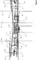
An den Endbereichen des Trägers 2 sind vier Flügel 10, 20, 30, 40 befestigt, die denselben radialen Abstand von der zentralen, vertikalen Achse 3 des Trägers 2 aufweisen. Der Flügel 10 ist gegenüber dem Flügel 30 und der Flügel 20 gegenüber dem Flügel 40 angeordnet. Alle vier Flügel 10, 20, 30, 40 sind jeweils um ihre vertikale Flügelachsen 11, 21, 31, 41 drehbar am Träger 2 angeordnet. Eine jeweilige Drehung von Träger 2 und Flügeln 10, 20, 30, 40 ist jedoch nicht unabhängig voneinander möglich, sondern Träger 2 und Flügel 10, 20, 30, 40 sind über ein Getriebe 8 gekoppelt. Das Getriebe 8 ist so ausgelegt, dass bei einer Drehung des Trägers 2 um 90 Grad alle vier Flügel 10, 20, 30, 40 in gleicher Drehrichtung um 45 Grad gedreht werden. Bei einer vollen Umdrehung des Trägers 2 werden die Flügel 10, 20, 30, 40 also um 180 Grad gedreht. Die als Pfeil 5 dargestellte Drehrichtung des Trägers 2 und der Flügel 10, 20, 30, 40 ist identisch, im dargestellten Fall erfolgt die Drehung 5 gegen den Uhrzeigersinn.At the end areas of the carrier 2 are four wings 10 . 20 . 30 . 40 attached, the same radial distance from the central, vertical axis 3 of the carrier 2 exhibit. The wing 10 is opposite the wing 30 and the wing 20 opposite the wing 40 arranged. All four wings 10 . 20 . 30 . 40 are each about their vertical wing axes 11 . 21 . 31 . 41 rotatable on the carrier 2 arranged. A respective rotation of the carrier 2 and wings 10 . 20 . 30 . 40 However, it is not possible to do it independently of each other, but to support it 2 and wings 10 . 20 . 30 . 40 are about a gearbox 8th coupled. The gear 8th is designed so that when the wearer turns 2 90 degrees all four wings 10 . 20 . 30 . 40 rotated in the same direction by 45 degrees. At a full turn of the vehicle 2 become the wings 10 . 20 . 30 . 40 So turned 180 degrees. The as arrow 5 illustrated direction of rotation of the carrier 2 and the wing 10 . 20 . 30 . 40 is identical, in the case shown, the rotation takes place 5 counterclockwise.

Die Flügel 10, 20, 30, 40 sind so eingestellt, dass in allen Drehstellungen des Trägers 2 und der Flügel 10, 20, 30, 40 die horizontalen Flügelachsen der sich gegenüberliegenden Flügel 10 und 30 bzw. 20 und 40 einen Winkel von 90 Grad zueinander aufweisen. Die horizontalen Flügelachsen der unmittelbar benachbarten Flügel 10, 20, 30, 40 weisen also einen Winkel von 45 Grad zueinander auf.The wings 10 . 20 . 30 . 40 are adjusted so that in all rotational positions of the wearer 2 and the wing 10 . 20 . 30 . 40 the horizontal wing axes of the opposite wings 10 and 30 respectively. 20 and 40 have an angle of 90 degrees to each other. The horizontal wing axes of the immediately adjacent wings 10 . 20 . 30 . 40 So they have an angle of 45 degrees to each other.

Die Windrichtung ist durch den Pfeil 4 dargestellt. Die Windströmung 4 trifft orthogonal auf die Flügelfläche 12 des Flügels 10 und übt auf diesen eine Kraft aus. Auf die Fläche 32 des gegenüberliegenden Flügels 30 wird hingegen keine oder nur eine geringe Kraft durch die Windströmung 4 ausgeübt, weil der Flügel 30 im Verhältnis zum Flügel 10 um 90 Grad verstellt ist und somit die horizontale Längsachse des gegenüberliegenden Flügels 30 parallel zur Windrichtung verläuft.The wind direction is through the arrow 4 shown. The wind flow 4 meets orthogonally on the wing surface 12 of the grand piano 10 and exerts a force on it. On the surface 32 the opposite wing 30 on the other hand, there is no or only a small force due to the wind flow 4 exercised because of the wing 30 in relation to the wing 10 is adjusted by 90 degrees and thus the horizontal longitudinal axis of the opposite wing 30 runs parallel to the wind direction.

Auf die beiden Flügel 20, 40 wird wie auf den Flügel 10 durch den Wind ebenfalls eine, wenn auch geringere, Kraft ausgeübt, so dass sich der Träger 2 insgesamt um seine zentrale, vertikale Achse 3 in der Richtung 5 gegen den Uhrzeigersinn dreht.On the two wings 20 . 40 will be like on the wing 10 By the wind also one, albeit lesser, force is exerted, so that the wearer 2 overall around its central, vertical axis 3 in that direction 5 turns counterclockwise.

Die Flügel 10, 20, 30, 40 verdicken sich zur Flügelachse 11, 21, 31, 41 hin. Die auf den Flügel 30 wirkende Kraft wird durch die konvexe Flügelform vermindert, wodurch sich der Wirkungsgrad weiter erhöht.The wings 10 . 20 . 30 . 40 thicken to the wing axis 11 . 21 . 31 . 41 out. The on the wing 30 acting force is reduced by the convex wing shape, which further increases the efficiency.

2 zeigt die Vertikalachswindkraftanlage 1 aus 1 in einer perspektivischen Vorderansicht. Es ist dargestellt, dass alle Flügel 10, 20, 30, 40 jeweils ein oberes Flügelsegment 10’, 20’, 30’, 40’ und ein unteres Flügelsegment 10“, 20“, 30“, 40“ aufweisen, wobei das obere und das untere Flügelsegment jeweils durch eine entlang der vertikalen Achse 11, 21, 31, 41 verlaufende Flügelwelle 13, 23, 33, 43 verbunden ist. Die Flügelwellen 13, 23, 33, 43 sind mittels eines Getriebes 8 mit der Drehung 5 des Trägers 2 gekoppelt. Bei einer Drehung 5 des Trägers 2 durch die Windkraft 4 werden also durch das Getriebe 8 auch die Flügelwellen 13, 23, 33, 43 und damit die Flügel 10, 20, 30, 40 angetrieben. 2 shows the vertical axis wind turbine 1 out 1 in a perspective front view. It is shown that all wings 10 . 20 . 30 . 40 one upper wing segment each 10 ' . 20 ' . 30 ' . 40 ' and a lower wing segment 10 " . 20 " . 30 " . 40 " each having the upper and the lower wing segments by one along the vertical axis 11 . 21 . 31 . 41 extending wing shaft 13 . 23 . 33 . 43 connected is. The wing waves 13 . 23 . 33 . 43 are by means of a gearbox 8th with the rotation 5 of the carrier 2 coupled. On a turn 5 of the carrier 2 through the wind power 4 So be through the transmission 8th also the wing waves 13 . 23 . 33 . 43 and with it the wings 10 . 20 . 30 . 40 driven.

Der Träger 2 weist ein oberes 2’ und ein im Wesentliches deckungsgleiches, unteres Teil 2“ auf, wobei das Getriebe 8 zwischen den beiden Teilen 2’ und 2“ angeordnet ist.The carrier 2 has an upper one 2 ' and a substantially congruent, lower part 2 ' on, with the gear 8th between the two parts 2 ' and 2 ' is arranged.

3 zeigt eine perspektivische Detailansicht der Vertikalachswindkraftanlage 1 aus 1. Es ist der mittlere Bereich mit dem Getriebe dargestellt, das als Kettengetriebe 8 ausgebildet ist. Entlang der zentralen, vertikalen Achse 3 des Trägers 2 verläuft die Trägerwelle 6, die am Träger 2 befestigt ist und das von ihm erzeugte Drehmoment auf einen (nicht gezeigten) Stromgenerator überträgt. 3 shows a perspective detail view of Vertikalachswindkraftanlage 1 out 1 , It is the middle area with the gear shown as a chain transmission 8th is trained. Along the central, vertical axis 3 of the carrier 2 runs the carrier wave 6 on the carrier 2 is fixed and transmits the torque generated by it to a (not shown) power generator.

Die Trägerwelle 6 treibt außerdem die Drehbewegung der Flügel 10, 20, 30, 40 an. Hierzu weist die Trägerwelle 6 im Bereich vom oberen 2’ und unteren Trägerteil 2“ vier in unterschiedlicher Höhe übereinander angeordnete, zentrale Trägerwellenzahnräder 16, 26, 36, 46 auf. Jedes der vier Trägerwellenzahnräder 16, 26, 36, 46 ist jeweils über eine Kette 9 mit einem von vier Flügelzahnrädern 14, 24, 34, 44 verbunden, die auf den vier Flügelwellen 13, 23, 33, 43 befestigt sind. Jedes der Flügelzahnräder 14, 24, 34, 44 ist auf derselben Höhe angeordnet, wie das mit ihm durch die Kette 9 verbundene Trägerwellenzahnrad 16, 26, 36, 46, so dass jede der vier Ketten 9 im Wesentlichen horizontal verläuft.The carrier wave 6 also drives the rotational movement of the wings 10 . 20 . 30 . 40 at. For this purpose, the carrier shaft 6 in the area from the top 2 ' and lower support part 2 ' four arranged at different heights one above the other, central carrier shaft gears 16 . 26 . 36 . 46 on. Each of the four carrier wave gears 16 . 26 . 36 . 46 is each about a chain 9 with one of four wing gears 14 . 24 . 34 . 44 connected on the four wing waves 13 . 23 . 33 . 43 are attached. Each of the wing gears 14 . 24 . 34 . 44 is at the same height as the one with it through the chain 9 Connected carrier shaft gear 16 . 26 . 36 . 46 so that each of the four chains 9 essentially horizontally.

Durch das Kettengetriebe 8 wird die Drehung der Flügel 10, 20, 30, 40 angetrieben. Das Übersetzungsverhältnis des Getriebes 8 bzw. eines Trägerzahnrad-/Flügelzahnradpaares 34 und 36, 44 und 46 usw. ist so gewählt, dass bei einer vollen Umdrehung des Trägers 2 jeder Flügel 10, 20, 30, 40 eine halbe Drehung ausführt.Through the chain transmission 8th will be the rotation of the wings 10 . 20 . 30 . 40 driven. The gear ratio of the transmission 8th or a Trägerzahnrad- / Flügelzahnradpaares 34 and 36 . 44 and 46 etc. is chosen so that during a full rotation of the carrier 2 every wing 10 . 20 . 30 . 40 makes a half turn.

4 zeigt eine perspektivische Vorderansicht einer zweiten Ausführungsform der Vertikalachswindkraftanlage. Das obere Trägerteil 2’ ist zum Teil transparent dargestellt, um zu zeigen, dass sich die Ausführungsform durch ein anderes Getriebe 8’ von der ersten Ausführungsform unterscheidet. Das Getriebe 8’ ist ebenfalls zwischen den beiden Teilen 2’ und 2“ des Trägers 2 angeordnet. 4 shows a front perspective view of a second embodiment of the vertical axis wind turbine. The upper carrier part 2 ' is shown partially transparent to show that the embodiment is due to a different transmission 8th' different from the first embodiment. The gear 8th' is also between the two parts 2 ' and 2 ' of the carrier 2 arranged.

Wie bei der ersten Ausführungsform sind vier Flügelzahnräder 14’, 24’, 34’, 44’ vorgesehen. Im Unterschied zur ersten Ausführungsform ist jedoch nur ein zentrales Trägerwellenzahnrad 60 vorhanden. Zwischen dem zentralen Trägerwellenzahnrad 60 und jedem der vier Flügelzahnräder 14’, 24’, 34’, 44’ sind jeweils drei, also insgesamt neun, in einer Reihe angeordnete und ineinander greifende Getriebezahnräder 50 angeordnet, über die die Drehung der Trägerwelle 6 bzw. des Trägerwellenzahnrades 60 über die Flügelzahnräder 14’, 24’, 34’, 44’ auf die Flügelwellen 13, 23, 33, 43 und die Flügel 10, 20, 30, 40 übertragen wird.As in the first embodiment, there are four vane gears 14 ' . 24 ' . 34 ' . 44 ' intended. In contrast to the first embodiment, however, only a central carrier shaft gear 60 available. Between the central carrier shaft gear 60 and each of the four wing gears 14 ' . 24 ' . 34 ' . 44 ' are each three, so a total of nine, arranged in a row and intermeshing transmission gears 50 arranged over which the rotation of the carrier shaft 6 or the carrier shaft gear 60 over the wing gears 14 ' . 24 ' . 34 ' . 44 ' on the wing waves 13 . 23 . 33 . 43 and the wings 10 . 20 . 30 . 40 is transmitted.

5 zeigt eine perspektivische Detailansicht einer dritten, besten Ausführungsform der Vertikalachswindkraftanlage. Diese Ausführungsform unterscheidet sich durch ein Kegelradgetriebe 8“ von der oben beschriebenen ersten und zweiten Ausführungsform. Das Kegelradgetriebe 8“ ist ebenfalls zwischen den beiden Teilen 2’ und 2“ des Trägers 2 angeordnet. Wie bei den anderen Ausführungsformen sind vier Flügelzahnräder 14“, 24“, 34“, 44“ vorgesehen, die mittels der vier Flügelwellen 13“, 23“, 33“, 43“ an den Flügeln 10, 20, 30, 40 befestigt sind. 5 shows a perspective detail view of a third, best embodiment of the Vertikalachswindkraftanlage. This embodiment differs by a bevel gear 8th" of the first and second embodiments described above. The bevel gear 8th" is also between the two parts 2 ' and 2 ' of the carrier 2 arranged. As with the other embodiments, there are four wing gears 14 " . 24 " . 34 " . 44 " provided by means of the four wing waves 13 " . 23 " . 33 " . 43 " on the wings 10 . 20 . 30 . 40 are attached.

Die Zähne jedes der vier Flügelzahnräder 14“, 24“, 34“, 44“ weisen jedoch nach unten und greifen jeweils in ein äußeres von insgesamt vier Kegelzahnrädern 51 ein. Jedes der vier Kegelzahnräder 51 ist an einem Ende einer radial verlaufenden Horizontalwelle 52 befestigt, an deren anderem Ende ein inneres Kegelzahnrad 53 befestigt ist. Insgesamt sind vier Horizontalwellen 52 vorgesehen, die eine kreuzförmige Anordnung bilden. Die vier inneren Kegelzahnräder 53 greifen gemeinsam in ein zentrales Trägerwellenzahnrad 60“ ein, dessen Zähne nach oben weisen. Alle vier Horizontalwellen 52 sind auf der gleichen horizontalen Höhe angeordnet.The teeth of each of the four wing gears 14 " . 24 " . 34 " . 44 " However, pointing down and each engage in an outer of a total of four bevel gears 51 one. Each of the four bevel gears 51 is at one end of a radially extending horizontal shaft 52 attached, at the other end an inner bevel gear 53 is attached. In total there are four horizontal waves 52 provided, which form a cross-shaped arrangement. The four inner bevel gears 53 grip together in a central carrier shaft gear 60 " one with teeth pointing upwards. All four horizontal waves 52 are arranged at the same horizontal height.

Der Träger 2 wird durch zwischen den beiden Teilen 2’ und 2“ befestigte, vertikale Versteifungselemente 54 verstärkt, die Wellenlager 55 für die Horizontalwellen 52 aufweisen und durch die die Horizontalwellen 52 geführt sind.The carrier 2 gets through between the two parts 2 ' and 2 ' fixed, vertical stiffening elements 54 reinforced, the shaft bearings 55 for the horizontal waves 52 and through which the horizontal waves 52 are guided.

Das Kegelzahnradgetriebe 8“ erlaubt eine sehr effiziente, verlustarme Übertragung des Drehmomentes von der zentralen Trägerwelle 6 auf die Flügel 10, 20, 30, 40.The bevel gearbox 8th" allows a very efficient, low-loss transmission of torque from the central carrier shaft 6 on the wings 10 . 20 . 30 . 40 ,

BezugszeichenlisteLIST OF REFERENCE NUMBERS

11
Windkraftanlage Wind turbine
22
Träger carrier
33
Trägerachse carrier axis
44
Windrichtung wind direction
55
Drehrichtung direction of rotation
66
Trägerwelle carrier wave
77
Stellvorrichtung locking device
88th
Getriebe transmission
99
Ketten chain
1010
Flügel wing
1111
Flügelachse wing axis
1212
Flügelfläche wing area
1313
Flügelwelle paddle shaft
1414
Flügelzahnrad wing gear
1616
Trägerzahnrad carrier gear
2020
Flügel wing
2121
Vertikale Flügelachse Vertical wing axis
2222
Flügelfläche wing area
2323
Flügelwelle paddle shaft
2424
Flügelzahnrad wing gear
2626
Trägerzahnrad carrier gear
3030
Flügel wing
3131
Flügelachse wing axis
3232
Flügelfläche wing area
3333
Flügelwelle paddle shaft
3434
Flügelzahnrad wing gear
3636
Trägerzahnrad carrier gear
4040
Flügel wing
4141
Flügelachse wing axis
4242
Flügelfläche wing area
4343
Flügelwelle paddle shaft
4444
Flügelzahnrad wing gear
4646
Trägerzahnrad carrier gear
5050
Getriebezahnräder Transmission gears
5151
Äußere Kegelzahnräder Outer bevel gears
5252
Horizontalwellen Horizontal shafts
5353
Innere Kegelzahnräder Inside bevel gears
5454
Versteifungselemente stiffeners
5555
Wellenlager shaft bearing
6060
Trägerwellenzahnrad Carrier wave gear

Claims (7)

Vertikalachswindkraftanlage (1) mit mindestens einem um die vertikale Achse (3) drehbaren Träger (2) und mindestens zwei an dem Träger (2) sich jeweils gegenüber angeordneten Flügeln (10, 20, 30, 40), dadurch gekennzeichnet, dass die Flügel (10, 20, 30, 40) jeweils um ihre vertikale Achse (11, 21, 31, 41) drehbar und mit dem Träger (2) derart gekoppelt sind, dass bei einer vollen Umdrehung des Trägers (2) jeweils eine halbe Umdrehung der Flügel (10, 20, 30, 40) erfolgt, wobei in jeder Drehstellung des Trägers (2) die Flügelflächen (12, 22, 32, 42) der sich jeweils gegenüber angeordneten Flügel (10, 20, 30, 40) orthogonal zueinander ausgerichtet sind.Vertical axis wind turbine ( 1 ) with at least one about the vertical axis ( 3 ) rotatable carrier ( 2 ) and at least two on the carrier ( 2 ) are each arranged opposite wings ( 10 . 20 . 30 . 40 ), characterized in that the wings ( 10 . 20 . 30 . 40 ) each about its vertical axis ( 11 . 21 . 31 . 41 ) and with the carrier ( 2 ) are coupled in such a way that during a full rotation of the carrier ( 2 ) each half a turn of the wing ( 10 . 20 . 30 . 40 ), wherein in each rotational position of the carrier ( 2 ) the wing surfaces ( 12 . 22 . 32 . 42 ) of each opposing wing ( 10 . 20 . 30 . 40 ) are aligned orthogonal to each other. Vertikalachswindkraftanlage (1) nach Anspruch 1, dadurch gekennzeichnet, dass vier Flügel (10, 20, 30, 40) vorgesehen sind. Vertical axis wind turbine ( 1 ) according to claim 1, characterized in that four wings ( 10 . 20 . 30 . 40 ) are provided. Vertikalachswindkraftanlage (1) nach Anspruch 1 oder Anspruch 2, dadurch gekennzeichnet, die Koppelung der Drehung von Träger (2) und Flügeln (10, 20, 30, 40) über ein Getriebe (8) erfolgt, welches vorzugsweise innerhalb des Trägers (2) angeordnet ist.Vertical axis wind turbine ( 1 ) according to claim 1 or claim 2, characterized in that the coupling of the rotation of the carrier ( 2 ) and wings ( 10 . 20 . 30 . 40 ) via a transmission ( 8th ), which preferably within the carrier ( 2 ) is arranged. Vertikalachswindkraftanlage (1) nach einem der vorhergehenden Ansprüche, dadurch gekennzeichnet, dass das Getriebe (8) als Kegelradgetriebe (8“) ausgebildet ist, welches für jeden Flügel (10, 20, 30, 40) jeweils eine Horizontalwelle (52) aufweist, an deren einem Ende ein Kegelzahnrad (53) befestigt ist, das in ein um die vertikale, zentrale Achse (3) drehbares Trägerwellenzahnrad (60“) eingreift, und an deren anderem Ende ein Kegelzahnrad (51) befestigt ist, das in ein dafür vorgesehenes, vertikal um die Flügelachse (11, 21, 31, 41) drehbares Flügelzahnrad 1(4“, 24“, 34“, 44“) eingreift, welches an einer Flügelwelle (13“, 23“, 33“, 43“) befestigt ist, die für jeden der vorzugsweise vier Flügel (10, 20, 30, 40) vorgesehen ist.Vertical axis wind turbine ( 1 ) according to one of the preceding claims, characterized in that the transmission ( 8th ) as a bevel gear ( 8th" ) is formed, which for each wing ( 10 . 20 . 30 . 40 ) each have a horizontal wave ( 52 ), at one end of a bevel gear ( 53 ), which is mounted in one about the vertical, central axis ( 3 ) rotatable carrier shaft gear ( 60 " ) engages, and at the other end a bevel gear ( 51 ), which is mounted in a designated, vertically around the wing axis ( 11 . 21 . 31 . 41 ) rotatable wing gear 1 ( 4 ' . 24 " . 34 " . 44 " ), which on a wing shaft ( 13 " . 23 " . 33 " . 43 " ) attached to each of the preferably four wings ( 10 . 20 . 30 . 40 ) is provided. Vertikalachswindkraftanlage (1) nach einem der vorhergehenden Ansprüche, dadurch gekennzeichnet, dass die Flügel (10, 20, 30, 40) jeweils ein oberes Flügelsegment (10’, 20’, 30’, 40’) und ein unteres Flügelsegment (10“, 20“, 30“, 40“) aufweisen, die jeweils durch eine vertikale Flügelwelle (13, 23, 33, 43) verbunden sind, wobei der Träger (2) zwischen den oberen (10’, 20’, 30’, 40’) und unteren Flügelsegmenten (10“, 20“, 30“, 40“) angeordnet ist.Vertical axis wind turbine ( 1 ) according to one of the preceding claims, characterized in that the wings ( 10 . 20 . 30 . 40 ) each have an upper wing segment ( 10 ' . 20 ' . 30 ' . 40 ' ) and a lower wing segment ( 10 " . 20 " . 30 " . 40 " ), each by a vertical wing wave ( 13 . 23 . 33 . 43 ), the carrier ( 2 ) between the upper ( 10 ' . 20 ' . 30 ' . 40 ' ) and lower wing segments ( 10 " . 20 " . 30 " . 40 " ) is arranged. Vertikalachswindkraftanlage (1) nach einem der vorhergehenden Ansprüche, dadurch gekennzeichnet, dass eine Stellvorrichtung (7) mit einem Windsensor, einer Steuerung und einem Stellmotor vorgesehen ist, die ausgebildet ist, den Träger (2) so zu drehen, dass einer der Flügel (10, 20, 30, 40) senkrecht zur Windrichtung (4) ausgerichtet ist.Vertical axis wind turbine ( 1 ) according to one of the preceding claims, characterized in that an adjusting device ( 7 ) is provided with a wind sensor, a control and a servomotor, which is designed, the carrier ( 2 ) so that one of the wings ( 10 . 20 . 30 . 40 ) perpendicular to the wind direction ( 4 ) is aligned. Vertikalachswindkraftanlage (1) nach einem der vorhergehenden Ansprüche, dadurch gekennzeichnet, dass sich die Flügel (10, 20, 30, 40) in Richtung Ihrer vertikalen Achse (11, 21, 31, 41) verdicken und die Flügelflächen (12, 22, 32, 42) eine konvexe Form aufweisen.Vertical axis wind turbine ( 1 ) according to one of the preceding claims, characterized in that the wings ( 10 . 20 . 30 . 40 ) in the direction of your vertical axis ( 11 . 21 . 31 . 41 ) and the wing surfaces ( 12 . 22 . 32 . 42 ) have a convex shape.
DE102013113863.2A 2012-12-27 2013-12-11 Vertical axle wind-power plant, has rotatable carrier arranged opposite to wings over axles, and positioning device provided with sensor and servomotor that are formed to rotate carrier such that wing is vertically aligned in wind direction Withdrawn DE102013113863A1 (en)

Priority Applications (1)

Application Number Priority Date Filing Date Title
DE102013113863.2A DE102013113863A1 (en) 2012-12-27 2013-12-11 Vertical axle wind-power plant, has rotatable carrier arranged opposite to wings over axles, and positioning device provided with sensor and servomotor that are formed to rotate carrier such that wing is vertically aligned in wind direction

Applications Claiming Priority (3)

Application Number Priority Date Filing Date Title
DE102012113134.1 2012-12-27
DE102012113134 2012-12-27
DE102013113863.2A DE102013113863A1 (en) 2012-12-27 2013-12-11 Vertical axle wind-power plant, has rotatable carrier arranged opposite to wings over axles, and positioning device provided with sensor and servomotor that are formed to rotate carrier such that wing is vertically aligned in wind direction

Publications (1)

Publication Number Publication Date
DE102013113863A1 true DE102013113863A1 (en) 2014-07-03

Family

ID=50928580

Family Applications (1)

Application Number Title Priority Date Filing Date
DE102013113863.2A Withdrawn DE102013113863A1 (en) 2012-12-27 2013-12-11 Vertical axle wind-power plant, has rotatable carrier arranged opposite to wings over axles, and positioning device provided with sensor and servomotor that are formed to rotate carrier such that wing is vertically aligned in wind direction

Country Status (1)

Country Link
DE (1) DE102013113863A1 (en)

Cited By (1)

* Cited by examiner, † Cited by third party
Publication number Priority date Publication date Assignee Title
WO2019002549A1 (en) * 2017-06-30 2019-01-03 Agile Wind Power Ag VERTICAL WIND POWER PLANT WITH ROTOR BLADE CARRYING PITCH MOTOR AND ASSEMBLY FOR SELF-PROOF AND METHOD FOR YOUR OPERATION

Cited By (2)

* Cited by examiner, † Cited by third party
Publication number Priority date Publication date Assignee Title
WO2019002549A1 (en) * 2017-06-30 2019-01-03 Agile Wind Power Ag VERTICAL WIND POWER PLANT WITH ROTOR BLADE CARRYING PITCH MOTOR AND ASSEMBLY FOR SELF-PROOF AND METHOD FOR YOUR OPERATION
US11519387B2 (en) 2017-06-30 2022-12-06 Agile Wind Power Ag Vertical wind turbine comprising rotor blade-supporting pitch motor, as well as kit for same, and method for operating same

Similar Documents

Publication Publication Date Title
EP1979611B1 (en) Rotating device to be used in a fluid
EP2710259B1 (en) Wind turbine gear mechanism
DE10003385A1 (en) Wind turbine
DE2737767C2 (en) Wind turbine
EP3555464B1 (en) Rotor arresting device for a wind turbine and method
WO2010045914A2 (en) Movable pitch drive
EP3752731B1 (en) Ram pressure machine
DE102013113863A1 (en) Vertical axle wind-power plant, has rotatable carrier arranged opposite to wings over axles, and positioning device provided with sensor and servomotor that are formed to rotate carrier such that wing is vertically aligned in wind direction
DE202009000125U1 (en) Wind turbine with a first rotor
DE4110540C2 (en) Wind turbine
EP3969743A1 (en) Rotor blade and wind turbine
DE10340112A1 (en) Wind power unit has vanes turning about a vertical axis with surface areas that can be altered according to the wind strength
EP3379077B1 (en) Rotary joint of a wind power plant and toothing for a rotary joint
DE10251388B4 (en) Rotor of a wind turbine
DE102009008805A1 (en) Wind turbine for use in generation of power, has vane whose surface is formed such that counter torque is less around vertical yaw axis by wind effect on vane and lesser than torque around yaw axis by wind effect on wind wheel
DE202012000907U1 (en) Flow turbine
EP2636892A2 (en) Wind power plant and method for generating of rotary energy from wind
DE102013211683B4 (en) Wind power plant
DE202020000307U1 (en) Vertical wind turbine
DE102009028946A1 (en) Wind turbine for converting wind force into electricity or mechanical force, has rotor blades tiltable between two positions around drag axes, and coupling device provided for synchronous pivoting of rotor blades between positions
DE102016110204A1 (en) Wind turbine and wind turbine
AT404972B (en) Rotor provided with a blade system for fluid-flow machines
DE202016007375U1 (en) Wind turbine
DE102012102876A1 (en) Wind turbine with two rotors
AT511955A4 (en) WIND TURBINE

Legal Events

Date Code Title Description
R119 Application deemed withdrawn, or ip right lapsed, due to non-payment of renewal fee