DE102013107059B4 - Process for the production and erection of a tubular tower construction - Google Patents
Process for the production and erection of a tubular tower construction Download PDFInfo
- Publication number
- DE102013107059B4 DE102013107059B4 DE102013107059.0A DE102013107059A DE102013107059B4 DE 102013107059 B4 DE102013107059 B4 DE 102013107059B4 DE 102013107059 A DE102013107059 A DE 102013107059A DE 102013107059 B4 DE102013107059 B4 DE 102013107059B4
- Authority
- DE
- Germany
- Prior art keywords
- flanges
- flange
- pair
- welded
- tubular
- Prior art date
- Legal status (The legal status is an assumption and is not a legal conclusion. Google has not performed a legal analysis and makes no representation as to the accuracy of the status listed.)
- Withdrawn - After Issue
Links
- 238000000034 method Methods 0.000 title claims abstract description 23
- 238000010276 construction Methods 0.000 title description 25
- 238000004519 manufacturing process Methods 0.000 title description 9
- 229910000831 Steel Inorganic materials 0.000 claims abstract description 13
- 239000010959 steel Substances 0.000 claims abstract description 13
- 241001016380 Reseda luteola Species 0.000 claims description 29
- 238000000926 separation method Methods 0.000 claims description 14
- 230000002093 peripheral effect Effects 0.000 claims description 6
- 239000004567 concrete Substances 0.000 description 8
- 238000009434 installation Methods 0.000 description 5
- IHQKEDIOMGYHEB-UHFFFAOYSA-M sodium dimethylarsinate Chemical class [Na+].C[As](C)([O-])=O IHQKEDIOMGYHEB-UHFFFAOYSA-M 0.000 description 5
- 239000011150 reinforced concrete Substances 0.000 description 4
- 241000196324 Embryophyta Species 0.000 description 3
- 230000035939 shock Effects 0.000 description 3
- 238000003466 welding Methods 0.000 description 3
- 244000089486 Phragmites australis subsp australis Species 0.000 description 2
- 238000007789 sealing Methods 0.000 description 2
- 230000004323 axial length Effects 0.000 description 1
- 238000005452 bending Methods 0.000 description 1
- 230000003111 delayed effect Effects 0.000 description 1
- 230000001419 dependent effect Effects 0.000 description 1
- 238000011161 development Methods 0.000 description 1
- 230000018109 developmental process Effects 0.000 description 1
- 238000007689 inspection Methods 0.000 description 1
- 238000012423 maintenance Methods 0.000 description 1
- 239000000463 material Substances 0.000 description 1
- 239000011513 prestressed concrete Substances 0.000 description 1
- 230000003716 rejuvenation Effects 0.000 description 1
- 125000006850 spacer group Chemical group 0.000 description 1
- 230000000087 stabilizing effect Effects 0.000 description 1
- 230000007704 transition Effects 0.000 description 1
Images




Classifications
-
- F—MECHANICAL ENGINEERING; LIGHTING; HEATING; WEAPONS; BLASTING
- F03—MACHINES OR ENGINES FOR LIQUIDS; WIND, SPRING, OR WEIGHT MOTORS; PRODUCING MECHANICAL POWER OR A REACTIVE PROPULSIVE THRUST, NOT OTHERWISE PROVIDED FOR
- F03D—WIND MOTORS
- F03D13/00—Assembly, mounting or commissioning of wind motors; Arrangements specially adapted for transporting wind motor components
- F03D13/20—Arrangements for mounting or supporting wind motors; Masts or towers for wind motors
-
- E—FIXED CONSTRUCTIONS
- E04—BUILDING
- E04H—BUILDINGS OR LIKE STRUCTURES FOR PARTICULAR PURPOSES; SWIMMING OR SPLASH BATHS OR POOLS; MASTS; FENCING; TENTS OR CANOPIES, IN GENERAL
- E04H12/00—Towers; Masts or poles; Chimney stacks; Water-towers; Methods of erecting such structures
- E04H12/02—Structures made of specified materials
- E04H12/08—Structures made of specified materials of metal
- E04H12/085—Details of flanges for tubular masts
-
- F—MECHANICAL ENGINEERING; LIGHTING; HEATING; WEAPONS; BLASTING
- F03—MACHINES OR ENGINES FOR LIQUIDS; WIND, SPRING, OR WEIGHT MOTORS; PRODUCING MECHANICAL POWER OR A REACTIVE PROPULSIVE THRUST, NOT OTHERWISE PROVIDED FOR
- F03D—WIND MOTORS
- F03D13/00—Assembly, mounting or commissioning of wind motors; Arrangements specially adapted for transporting wind motor components
- F03D13/10—Assembly of wind motors; Arrangements for erecting wind motors
-
- F—MECHANICAL ENGINEERING; LIGHTING; HEATING; WEAPONS; BLASTING
- F05—INDEXING SCHEMES RELATING TO ENGINES OR PUMPS IN VARIOUS SUBCLASSES OF CLASSES F01-F04
- F05B—INDEXING SCHEME RELATING TO WIND, SPRING, WEIGHT, INERTIA OR LIKE MOTORS, TO MACHINES OR ENGINES FOR LIQUIDS COVERED BY SUBCLASSES F03B, F03D AND F03G
- F05B2240/00—Components
- F05B2240/40—Use of a multiplicity of similar components
-
- Y—GENERAL TAGGING OF NEW TECHNOLOGICAL DEVELOPMENTS; GENERAL TAGGING OF CROSS-SECTIONAL TECHNOLOGIES SPANNING OVER SEVERAL SECTIONS OF THE IPC; TECHNICAL SUBJECTS COVERED BY FORMER USPC CROSS-REFERENCE ART COLLECTIONS [XRACs] AND DIGESTS
- Y02—TECHNOLOGIES OR APPLICATIONS FOR MITIGATION OR ADAPTATION AGAINST CLIMATE CHANGE
- Y02B—CLIMATE CHANGE MITIGATION TECHNOLOGIES RELATED TO BUILDINGS, e.g. HOUSING, HOUSE APPLIANCES OR RELATED END-USER APPLICATIONS
- Y02B10/00—Integration of renewable energy sources in buildings
- Y02B10/30—Wind power
-
- Y—GENERAL TAGGING OF NEW TECHNOLOGICAL DEVELOPMENTS; GENERAL TAGGING OF CROSS-SECTIONAL TECHNOLOGIES SPANNING OVER SEVERAL SECTIONS OF THE IPC; TECHNICAL SUBJECTS COVERED BY FORMER USPC CROSS-REFERENCE ART COLLECTIONS [XRACs] AND DIGESTS
- Y02—TECHNOLOGIES OR APPLICATIONS FOR MITIGATION OR ADAPTATION AGAINST CLIMATE CHANGE
- Y02E—REDUCTION OF GREENHOUSE GAS [GHG] EMISSIONS, RELATED TO ENERGY GENERATION, TRANSMISSION OR DISTRIBUTION
- Y02E10/00—Energy generation through renewable energy sources
- Y02E10/70—Wind energy
- Y02E10/72—Wind turbines with rotation axis in wind direction
-
- Y—GENERAL TAGGING OF NEW TECHNOLOGICAL DEVELOPMENTS; GENERAL TAGGING OF CROSS-SECTIONAL TECHNOLOGIES SPANNING OVER SEVERAL SECTIONS OF THE IPC; TECHNICAL SUBJECTS COVERED BY FORMER USPC CROSS-REFERENCE ART COLLECTIONS [XRACs] AND DIGESTS
- Y02—TECHNOLOGIES OR APPLICATIONS FOR MITIGATION OR ADAPTATION AGAINST CLIMATE CHANGE
- Y02E—REDUCTION OF GREENHOUSE GAS [GHG] EMISSIONS, RELATED TO ENERGY GENERATION, TRANSMISSION OR DISTRIBUTION
- Y02E10/00—Energy generation through renewable energy sources
- Y02E10/70—Wind energy
- Y02E10/728—Onshore wind turbines
Landscapes
- Engineering & Computer Science (AREA)
- Chemical & Material Sciences (AREA)
- Life Sciences & Earth Sciences (AREA)
- Mechanical Engineering (AREA)
- Sustainable Energy (AREA)
- Combustion & Propulsion (AREA)
- Sustainable Development (AREA)
- General Engineering & Computer Science (AREA)
- Architecture (AREA)
- Materials Engineering (AREA)
- Wood Science & Technology (AREA)
- Civil Engineering (AREA)
- Structural Engineering (AREA)
- Wind Motors (AREA)
Abstract
Verfahren zum Errichten eines Rohrturmbauwerkes (6),- wobei Stahlblech zu einem im Wesentlichen im Querschnitt ringförmigen Rohrabschnitt (1) gebogen wird und entlang einer Längskante (2) zu einem geschlossenen Rohr verschweißt wird,- in das Rohr (6)entlang geplanter axialer Trennungslinien (20) je ein Paar axialer Flansche (7, 8) innen oder außen auf die Rohrwandung (4) aufgeschweißt wird, wobei die Flansche (7, 8) zur Montage miteinander verbunden sind, wobei je ein Flanschpaar (7, 8) in Umfangsrichtung nebeneinander liegend axial verlaufend angeordnet ist,- wobei entlang geplanter Trennungslinien (20), welche zwischen zwei Flanschen (7, 8) eines Flanschpaares verlaufen, das Rohr (6) getrennt wird, sodass zumindest zwei Teilschalen (6a) des Rohrs gebildet werden, welche entlang axialer Kanten (21) je einen Flansch (7, 8) besitzen und- zur Errichtung des Rohrturmbauwerks (6) die Teilschalen (6a) mittels der Flansche (7, 8)eines Flanschpaares aneinander angeordnet werden und durch die Flansche(7, 8) je eines Flanschpaares hindurch zu dem Rohrturmbauwerk (6) verbunden werden.Method for erecting a tubular tower structure (6), - wherein steel sheet is bent to a substantially cross-sectionally tubular pipe section (1) and welded along a longitudinal edge (2) to a closed tube, - in the pipe (6) along planned axial dividing lines (20) each a pair of axial flanges (7, 8) inside or outside of the pipe wall (4) is welded, wherein the flanges (7, 8) are connected to each other for mounting, each with a pair of flanges (7, 8) in the circumferential direction lying alongside one another axially extending, - along which planned dividing lines (20) which extend between two flanges (7, 8) of a pair of flanges, the tube (6) is separated, so that at least two partial shells (6a) are formed of the tube, which along axial edges (21) each having a flange (7, 8) and- for the erection of the tubular tower structure (6) the partial shells (6a) by means of the flanges (7, 8) of a pair of flanges are arranged against each other and through the flanges (7, 8) each of a pair of flanges are connected to the tubular tower structure (6).
Description
Die Erfindung betrifft ein Verfahren zum Errichten eines Rohrturmbauwerkes gemäß dem Patentanspruch 1.The invention relates to a method for erecting a tubular tower construction according to
Rohrturmbauwerke sind bekannt, insbesondere als Träger von Windenergieanlagen. Hierbei ist es insbesondere bekannt, aus Stahlblech Rohrabschnitte zu fertigen und die Rohrabschnitte übereinander mit umlaufenden Schweißnähten zu einem Rohrturm zusammenzusetzen, welcher an seinem oberen Ende eine Windenergiegondel aufnimmt. Um die einzelnen Segmente miteinander zu verbinden ist es bekannt, diese entweder zu verschweißen oder mit aufeinanderliegenden, umlaufenden Flanschen so zu versehen, dass die aufeinander liegenden Flansche miteinander verschraubt werden können.Pipe tower structures are known, especially as a carrier of wind turbines. In this case, it is known in particular to manufacture pipe sections from sheet steel and to assemble the pipe sections one above the other with circumferential welds to form a tubular tower which receives a wind energy cone at its upper end. In order to connect the individual segments to one another, it is known to either weld them or to provide them with peripheral, flanging flanges in such a way that the superimposed flanges can be screwed together.
Darüber hinaus ist es bekannt, derartige Turmbauwerke aus Teilschalen auszubilden, wobei die Teilschalen an ihren Längskanten Flansche besitzen, mit denen diese Teilschalen aneinander geschraubt werden.In addition, it is known to form such tower structures of partial shells, wherein the partial shells have at their longitudinal edges flanges with which these partial shells are screwed together.
Aus der
Es hat sich herausgestellt, dass die Errichtung von Rohrturmbauwerken aus Längsschalen, bei denen zunächst die Längsschalenwandungen errichtet werden und dann auf die Längsschalenwandungen Flansche aufgeschweißt werden, an der Baustelle oft zu Montageproblemen durch Verzug und dergleichen führt.It has been found that the construction of tubular tower structures from longitudinal shells, in which first the longitudinal shell walls are built and then welded to the longitudinal shell walls flanges, often leads to assembly problems due to distortion and the like at the construction site.
Aus der
Aus der
Aus der
Aus der
Aus der
Aus der
Aus der
Aus der
Aus der
Aufgabe der Erfindung ist es, ein Verfahren zu schaffen, mit dem derartige Turmbauwerke schneller und mit höherer Präzision und Passgenauigkeit errichtet werden können und mit dem die Montage an der Baustelle erleichtert wird.The object of the invention is to provide a method by which such tower structures can be built faster and with greater precision and accuracy of fit and with the assembly at the site is facilitated.
Die Aufgabe wird mit einem Verfahren mit den Merkmalen des Anspruchs 1 gelöst.The object is achieved by a method having the features of
Vorteilhafte Weiterbildungen sind in den hiervon abhängigen Unteransprüchen gekennzeichnet.Advantageous developments are characterized in the dependent claims.
Die Erfindung betrifft demnach ein Verfahren zum Errichten eines Rohrturmbauwerks, wobei Stahlblech zu einem im Wesentlichen im Querschnitt ringförmigen Rohrabschnitt gebogen wird und entlang einer Längskante zu einem geschlossenen Rohr verschweißt wird, in das Rohr entlang geplanter axialer Trennungslinien je ein Paar axialer Flansche innen oder außen auf die Rohrwandung aufgeschweißt wird, wobei die Flansche zur Montage miteinander verbunden sind, wobei je ein Flanschpaar in Umfangsrichtung nebeneinander liegend axial verlaufend angeordnet ist, wobei entlang geplanter Trennungslinien, welche zwischen zwei Flanschen eines Flanschpaares verlaufen, das Rohr getrennt wird, sodass zumindest zwei Teilschalen des Rohrs gebildet werden, welche entlang axialer Kanten je einen Flansch besitzen und zur Errichtung des Rohrturmbauwerks die Teilschalen mittels der Flansche eines Flanschpaares aneinander angeordnet werden und durch die Flansche je eines Flanschpaares hindurch zu dem Rohrturmbauwerk verbunden werden.Accordingly, the invention relates to a method for erecting a tubular tower structure, wherein steel sheet is bent to a tubular section substantially annular in cross-section and welded along a longitudinal edge to form a closed tube, inside the tube along a planned axial dividing lines depending on a pair of axial flanges inside or outside the pipe wall is welded, wherein the flanges are connected to each other for mounting, wherein each pair of flanges in the circumferential direction next to each other is arranged axially extending, wherein along planned dividing lines which extend between two flanges of a pair of flanges, the tube is separated, so that at least two partial shells of Pipe are formed, which each have a flange along axial edges and the erection of the tubular tower structure, the partial shells are arranged by means of the flanges of a pair of flanges together and through the flanges of each pair of flanges through to the Rohrturmba be connected.
Ein erfindungsgemäßes Turmbauwerk dient insbesondere als Unterbauturm, um einen herkömmlichen Turm zur Aufnahme von Windenergieanlagen aufzusetzen und hierdurch eine größere Höhe und damit bessere Winderreichbarkeit zu erzielen.A tower construction according to the invention serves in particular as a substructure tower in order to set up a conventional tower for accommodating wind energy installations and thereby to achieve a greater height and thus better wind accessibility.
Für größere Höhen von derartigen Turmbauwerken ist es notwendig, den Turmquerschnitt zu vergrößern, da nur dann die erforderliche Stand- und Knicksicherheit erzielt werden kann. Üblicherweise werden derartige Türme aus im Querschnitt kreisringförmigen Turmsegmenten erstellt, übereinander gesetzt und miteinander verbunden. Aufgrund der üblichen Brückenhöhe in Deutschland lassen sich sehr großen Turmquerschnitte aus einteiligen Rohrabschnitten oder Rohrsegmenten nicht mehr realisieren.For larger heights of such tower structures, it is necessary to increase the tower cross-section, as only then the required stability and buckling security can be achieved. Usually, such towers are created from circular-section tower-shaped tower segments, placed one above the other and connected to each other. Due to the usual bridge height in Germany, very large tower cross-sections made of one-piece pipe sections or pipe segments can no longer be realized.
Hierdurch ist es notwendig, um die Durchfahrthöhe einzuhalten, derartige, sehr breite Türme mit mehr als 4,5 m Durchmesser am Fuß aus Teilschalen, d.h. Ringsegmenten zu einem vollständigen Ring zusammenzusetzen und - so notwendig - mehrere dieser Ringe übereinanderzusetzen.This makes it necessary to comply with the clearance height, such, very wide towers with more than 4.5 m diameter at the foot of partial shells, i. Ring segments to form a complete ring and - if necessary - several of these rings on top of each other.
Grundsätzlich ist es bekannt, derartige sogenannte längsorientierte Schalen zu erstellen und diese Schalen am Einbauort zu einem Rohr zusammenzusetzen. Es hat sich hierbei jedoch herausgestellt, dass die Präzision und die Toleranzen derart groß sind, dass die Montage sehr oft verzögert wird und unnötig erschwert wird. In principle, it is known to create such so-called longitudinally oriented shells and to assemble these shells at the installation site to form a tube. It has been found, however, that the precision and the tolerances are so large that the assembly is very often delayed and unnecessarily difficult.
Erfindungsgemäß wird das Rohrturmbauwerk zunächst vollständig am Herstellungsort hergestellt und errichtet, so dass das Rohrturmbauwerk in Teillängen, die noch transportierbar sind oder, bei einer noch transportierbaren Länge, in seiner vollen Länge errichtet wird. Hierzu werden aus Stahlblech entsprechende Bahnen beziehungsweise Platinen gefertigt, welche dann gerollt werden, so dass sie mit einer Längskante aneinander stoßen und ein Ringsegment oder ein Rohrsegment bilden. Dieses Rohrsegment wird dann an dieser Stoßkante verschweißt. Weitere Rohrsegmente werden hierauf aufgesetzt und ebenfalls verschweißt, bis ein vollständiges Rohrturmbauwerk ausgebildet ist. In dieses Rohrturmbauwerk werden anschließend, entsprechend einer gewünschten Anzahl von Teilschalen, axial verlaufend Flansche von außen auf die Turmbauwerkswandung oder von innen auf die Turmbauwerkswandung aufgeschweißt, wobei immer zwei Flansche nebeneinander liegend ein Flanschpaar bilden und aufgeschweißt werden. Bei einem Rohrturmbauwerk, welches aus vier Teilschalen besteht, werden somit insgesamt acht Flansche in vier Paaren außen oder innen aufgeschweißt. Anschließend erfolgt eine Trennung des Rohres zwischen den jeweiligen Flanschpaaren in die entsprechenden Teilschalen. Die Teilschalen werden anschließend zur Baustelle transportiert und dort entsprechend wieder zu einem Rohrturmbauwerk zusammengestellt und durch die Flansche hindurch miteinander verbunden.According to the invention, the tubular tower construction is initially completely manufactured and erected at the place of manufacture, so that the tubular tower structure is built in partial lengths that are still transportable or, at a still transportable length, in its full length. For this purpose, corresponding sheets or boards are made of sheet steel, which are then rolled so that they abut each other with a longitudinal edge and form a ring segment or a pipe segment. This pipe segment is then welded to this abutting edge. Other pipe segments are placed on top and also welded until a complete tubular tower structure is formed. In this Rohrturmbauwerk are then welded, according to a desired number of part shells, axially extending flanges from the outside on the Turmbauwerkswandung or from the inside on Turmbauwerkswandung, always two flanges next to each other form a pair of flanges and are welded. In a tubular tower structure, which consists of four shells, thus a total of eight flanges are welded in four pairs outside or inside. Subsequently, a separation of the tube between the respective flange pairs in the corresponding sub-shells. The partial shells are then transported to the construction site and there correspondingly reassembled to form a tubular tower structure and connected to each other through the flanges.
Bei der Erfindung ist von Vorteil, dass die Flansche und die Verschweißung der Flansche mit der Rohrturmbauwerkswandung außerordentlich präzise und nachvollziehbar genau sind. Zudem können die Flansche an dem gesamten Rohrturmbauwerk in besonders guter Weise ausgerichtet und befestigt werden, um eine Schweißung herbeizuführen. Ferner ist von Vorteil, dass diese Schweißungen und das anschließende Trennen des Rohrturmbauwerks in die Schalenelemente unter nachvollziehbaren Bedingungen am Herstellort erfolgt, wobei eine entsprechende Nachprüfung am Herstellort erfolgen kann.In the invention, it is advantageous that the flanges and the welding of the flanges with the tubular tower construction wall are extremely precise and comprehensibly accurate. In addition, the flanges can be aligned and fastened to the entire tubular tower structure in a particularly good manner, in order to bring about a weld. A further advantage is that these welds and the subsequent separation of the tubular tower structure in the shell elements under comprehensible conditions at the place of manufacture, with a corresponding inspection can be made at the place of manufacture.
Am Einsatzort muss lediglich aus z.B. vier Schalen der gesamte Turm zusammengestellt und verschraubt werden.At the place of installation, it is only necessary to use e.g. four shells are assembled and bolted the entire tower.
Zudem hat sich herausgestellt, dass bei der erfindungsgemäßen Methode, wonach die Flansche von innen oder außen auf die Wandung aufgeschweißt werden, sich eine höhere Stabilität ergibt als bei Flanschen, die an die Stoßfläche angeschweißt werden.In addition, it has been found that in the method according to the invention, according to which the flanges are welded on the wall from the inside or outside, a higher stability results than with flanges which are welded to the abutment surface.
Die Erfindung wird anhand einer Zeichnung beispielhaft erläutert. Es zeigen dabei
-
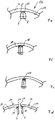
1a ein ringförmiges Rohr mit einer Längsschweißnaht als Ausgangsbauwerk; -
1b das Rohr nach1a mit schematisch dargestellt aufgeschweißten Flanschen; -
1c die Situation nach der Trennung in zwei Turmbauwerksschalen zwischen den Flanschpaaren; -
2 ein Rohrturmbauwerk mit innenliegenden Flanschen, die miteinander verbunden sind; -
3 ein Rohrturmbauwerk mit außenliegenden Flanschen, die miteinander verbunden sind; -
4 ein Rohrturmbauwerk aus mehreren Rohrabschnitten, wobei die Trennlinien bzw. Flansche fluchtend angeordnet sind; -
5 ein Rohrturmbauwerk aus mehreren Rohrabschnitten mit versetzt zueinander verlaufenden Trennlinien bzw. Flanschen; -
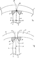
6a ein Ausschnitt aus einer Rohrturmbauwerkswandung; -
6b die Wandung nach6a mit einem ersten aufgesetzten und verschweißten Flansch (nicht erfindungsgemäß); -
6c die Wandung mit einem zweiten aufgesetzten und entlang einer Stoßkante verschweißten Flansch (nicht erfindungsgemäß); -
6d die Trennlinie in der Wandung des Rohrturmbauwerks zwischen den beiden Flanschen; -
6e das zwischen den Flanschen getrennte Rohrturmbauwerk mit einer auf den zweiten Flansch aufgesetzten zweiten Kehlnaht entlang der Stoßkante; -
7a-f den Anschluss der Flansche als Vollanschluss; -
8a-d Flansche mit Futterblechen; -
9 das Rohrturmbauwerk in einer Ansicht von außen aus mehreren Rohrsegmenten, die miteinander verschweißt sind; -
10 den Fuß des Rohrturmbauwerkes mit einem doppelten Ringflansch nach innen und nach außen zur Befestigung auf einem Fundament; -
11 den Ringflansch mit der Rohrturmbauwerkswandung und einem Teil eines längs verlaufenden Flansches in einer teilgeschnittenen Ansicht; -
12 den Kopfbereich des Rohrturmbauwerks mit einem innen liegenden Kreisflansch zur Befestigung weiterer Rohrelemente; -
13 den Kopfbereich des Rohrturmbauwerks in einer teilgeschnittenen Ansicht; -
14 die Ansicht von innen auf eine Rohrturmbauwerksschale mit je einem längs verlaufenden Flansch an den Längskanten; -
15 dieRohrturmbauwerksschale nach 10 in einer teilgeschnittenen Draufsicht auf den Fußbereich mit einem innen und außen verlaufenden Ringflansch; -
16 den Kopfbereich der Rohrturmbauwerksschale mit einem innen verlaufenden Flansch.
-
1a an annular tube with a longitudinal weld as a parent structure; -
1b the pipe after1a with schematically illustrated welded-on flanges; -
1c the situation after separation into two tower building shells between the pairs of flanges; -
2 a Rohrturmbauwerk with internal flanges, which are interconnected; -
3 a Rohrturmbauwerk with external flanges, which are interconnected; -
4 a Rohrturmbauwerk of several pipe sections, the dividing lines or flanges are arranged in alignment; -
5 a Rohrturmbauwerk of several pipe sections with staggered separating lines or flanges; -
6a a section of a Rohrturmbauwerkswandung; -
6b the wall after6a with a first attached and welded flange (not according to the invention); -
6c the wall with a second attached and welded along a joint edge flange (not according to the invention); -
6d the dividing line in the wall of the tubular tower structure between the two flanges; -
6e the separate between the flanges tubular tower structure with a second flange on the second fillet weld along the abutting edge; -
7a-f the connection of the flanges as a full connection; -
8a-d Flanges with lining sheets; -
9 the Rohrturmbauwerk in an outside view of a plurality of pipe segments, which are welded together; -
10 the base of the tubular tower structure with a double ring flange inwards and outwards for attachment to a foundation; -
11 the annular flange with the Rohrturmbauwerkswandung and a part of a longitudinal flange in a partially sectioned view; -
12 the head area of the tubular tower structure with an internal circular flange for attachment of further pipe elements; -
13 the head area of the tubular tower structure in a partially sectioned view; -
14 the view from the inside of a tubular tower building shell, each with a longitudinal flange on the longitudinal edges; -
15 the tubular tower building shell after10 in a partially sectioned plan view of the foot region with an inner and outer annular flange; -
16 the head area of the tubular tower building shell with an internal flange.
Zur Herstellung und Errichtung eines Rohrturmbauwerkes wird Stahlblech einer gewünschten Breite, Länge und Dicke so gebogen, dass es ein kreisrundes Rohr oder einen kreisrunden Rohrabschnitt bildet. Für den Fall sehr großer Durchmesser können einzelne Rohrabschnittsegmente mit mehreren längsverlaufenden Schweißnähten zu einem Rohrabschnitt (
Die Rohrabschnitte
Das erfindungsgemäße Verfahren sieht vor, einen oder mehrere axial miteinander verschweißte Rohrabschnitte
Um ein derartiges Rohrturmbauwerk
Hierfür wird das Rohrturmbauwerk
Im einfachsten Fall weist ein Rohrturmbauwerk
Zur Montage der Flansche
Bei einer ersten möglichen Ausführung der Anordnung der Flansche
Anschließend wird der zweite Flansch
Bei einer weiteren vorteilhaften Ausführungsform werden die Flansche
Insbesondere in dem Bereich, in dem die beiden Breitseiten
Diese Schweißnahtwurzel
Derartige Futterbleche
Darüber hinaus können H- beziehungsweise Doppel-T-Dichtelemente 19 zwischen den Kanten
Ein entsprechendes Rohrturmbauwerk
Zur Verbindung eines solchen Rohrturmbauwerks
Ein derartiger Ringflansch
Ein derartiger Ringflansch
Wird das Rohrturmbauwerk
Bei einer Ausführungsform, bei der das Rohrturmbauwerk
Eine Teilschale
Die Teilschale
Ein in der Gestalt hergestellte Teilschale
Bei der Erfindung ist von Vorteil, dass ein Rohrturmbauwerk
An einer Errichtungsstelle des Rohrturmbauwerks werden die Teilschalen
BezugszeichenlisteLIST OF REFERENCE NUMBERS
- 11
- Rohrabschnittpipe section
- 22
- axiale Kantenaxial edges
- 33
- SchweißnahtWeld
- 44
- Rohrwandungpipe wall
- 55
- radiale Stirnflächeradial face
- 66
- RohrturmbauwerkTubular tower building
- 6a6a
- Teilschalepartial shell
- 7, 87, 8
- Flanscheflanges
- 1111
- Schraublöcherscrew
- 1212
- Breitseitenbroadsides
- 1313
- FutterblecheShims
- 1414
- Innenflächepalm
- 15, 1615, 16
- Schmalseitennarrow sides
- 1717
- Kehlnahtfillet
- 1818
- Kehlnahtfillet
- 1919
- Dichtelementsealing element
- 2020
- TrennungslinieDividing line
- 2121
- Kantenedge
- 2222
- Kerbgrundnotch base
- 2323
- Schweißnahtwurzelweld root
- 2424
- Ringflanschering flanges
- 24a24a
- Ringflanschsegmentring flange
- 2525
- Stirnflächeface
- 2626
- Stirnflächeface
- 2727
- innere Umfangsflächeinner peripheral surface
- 2828
- äußere Umfangsflächeouter peripheral surface
- 2929
- Stirnflächeface
- 3030
- AnschlussringAttachment ring
- 3131
- Flanschringflange
- 32,32
- 33 Lochreihen33 rows of holes
- 3434
- Aufstandsflächefootprint
- 3535
- Flächearea
- 3636
- innere umlaufende Stirnflächeinner circumferential face
- 3737
- äußere umlaufende Stirnflächeouter circumferential face
- 3838
- Ringstegring land
- 3939
- radiale Kanteradial edge
- 4040
- Kanteedge
- 4141
- Längsspantlongitudinal frame
- 4242
- Ringspantenring frames
- 4343
- RingspantsegmenteRingspantsegmente
Claims (12)
Priority Applications (7)
| Application Number | Priority Date | Filing Date | Title |
|---|---|---|---|
| DE102013107059.0A DE102013107059B4 (en) | 2013-07-04 | 2013-07-04 | Process for the production and erection of a tubular tower construction |
| ES14165927T ES2646046T5 (en) | 2013-07-04 | 2014-04-25 | Procedure for the manufacture and assembly of a tubular tower type construction |
| PT141659276T PT2824257T (en) | 2013-07-04 | 2014-04-25 | Method for preparation and erection of a tubular tower structure |
| PL14165927.6T PL2824257T5 (en) | 2013-07-04 | 2014-04-25 | Method for preparation and erection of a tubular tower structure |
| DK14165927.6T DK2824257T4 (en) | 2013-07-04 | 2014-04-25 | Method for manufacturing and erecting a tubular tower structure |
| EP14165927.6A EP2824257B2 (en) | 2013-07-04 | 2014-04-25 | Method for preparation and erection of a tubular tower structure |
| FIEP14165927.6T FI2824257T4 (en) | 2013-07-04 | 2014-04-25 | Method for preparation and erection of a tubular tower structure |
Applications Claiming Priority (1)
| Application Number | Priority Date | Filing Date | Title |
|---|---|---|---|
| DE102013107059.0A DE102013107059B4 (en) | 2013-07-04 | 2013-07-04 | Process for the production and erection of a tubular tower construction |
Publications (2)
| Publication Number | Publication Date |
|---|---|
| DE102013107059A1 DE102013107059A1 (en) | 2015-01-08 |
| DE102013107059B4 true DE102013107059B4 (en) | 2018-12-06 |
Family
ID=50630583
Family Applications (1)
| Application Number | Title | Priority Date | Filing Date |
|---|---|---|---|
| DE102013107059.0A Withdrawn - After Issue DE102013107059B4 (en) | 2013-07-04 | 2013-07-04 | Process for the production and erection of a tubular tower construction |
Country Status (7)
| Country | Link |
|---|---|
| EP (1) | EP2824257B2 (en) |
| DE (1) | DE102013107059B4 (en) |
| DK (1) | DK2824257T4 (en) |
| ES (1) | ES2646046T5 (en) |
| FI (1) | FI2824257T4 (en) |
| PL (1) | PL2824257T5 (en) |
| PT (1) | PT2824257T (en) |
Families Citing this family (24)
| Publication number | Priority date | Publication date | Assignee | Title |
|---|---|---|---|---|
| DE102013107059B4 (en) | 2013-07-04 | 2018-12-06 | SIAG Industrie GmbH | Process for the production and erection of a tubular tower construction |
| DE102015204695A1 (en) * | 2015-03-16 | 2016-10-13 | Rwe Innogy Gmbh | Foundation pile for a wind turbine |
| DE102015211269A1 (en) | 2015-06-18 | 2016-12-22 | Wobben Properties Gmbh | Wind turbine tower and wind turbine |
| DE102015110344A1 (en) | 2015-06-26 | 2016-12-29 | Eno Energy Systems Gmbh | Section of a tower section, a tower and a method of making a section of a tower section |
| DE102016205447A1 (en) * | 2016-04-01 | 2017-10-05 | Innogy Se | Support structure for a wind turbine |
| DE102016118549A1 (en) * | 2016-08-02 | 2018-02-08 | Eno Energy Systems Gmbh | A method for separating a shell of at least one tower section of a tower and a portable separation device |
| EP3278915B1 (en) * | 2016-08-02 | 2021-07-21 | eno energy systems GmbH | A method for separating a shell of at least one tower section of a tower and a transportable separating device |
| EP3339636A1 (en) * | 2016-12-22 | 2018-06-27 | Nordex Energy GmbH | Steel tower for a wind power installation, and a method for the production thereof |
| EP3339635A1 (en) * | 2016-12-22 | 2018-06-27 | Nordex Energy GmbH | Steel tower for a wind turbine and method for producing the same |
| DE102017120488A1 (en) | 2017-09-06 | 2019-03-07 | Nordex Energy Gmbh | Tower of a wind energy plant and longitudinal reinforcement for a tower of a wind energy plant |
| CN107654338B (en) | 2017-09-30 | 2019-09-03 | 新疆金风科技股份有限公司 | Tower section, tower frame, wind turbine and method for manufacturing tower section |
| DE102017125716A1 (en) * | 2017-11-03 | 2019-05-09 | Eno Energy Systems Gmbh | Method for erecting a tower with a multi-part tower section and sub-section of a multi-part tower section of a tower |
| DE102017125717A1 (en) * | 2017-11-03 | 2019-05-09 | Eno Energy Systems Gmbh | Method for producing a subsection of a multi-part tower section |
| KR102447634B1 (en) * | 2017-12-11 | 2022-09-26 | 에노바치온 게엠베하 | Partial section manufacturing method of multipart tower section of tower and partial section of multipart tower section of tower |
| CN109185590B (en) * | 2018-10-31 | 2024-07-02 | 江阴市扬子管件有限公司 | Energy-saving environment-friendly efficient collecting pipe and production process thereof |
| KR102176840B1 (en) * | 2018-12-07 | 2020-11-10 | 김성섭 | Module Erection Method For Inner Flue Chimney |
| EP3835516B1 (en) * | 2019-12-11 | 2022-08-10 | Siemens Gamesa Renewable Energy Innovation & Technology, S.L. | Method for building a metallic tower for a wind turbine |
| CN113404645B (en) * | 2021-06-15 | 2024-04-02 | 中铁上海设计院集团有限公司 | A prefabricated wind power tower connected by bolt U ring and its construction method |
| CN113751867A (en) * | 2021-08-09 | 2021-12-07 | 成都凯天电子股份有限公司 | Laser welding processing method for thin-wall revolving body component |
| CN114294173A (en) * | 2021-12-20 | 2022-04-08 | 山东中车风电有限公司 | High-power generator set tower and construction method thereof |
| CN114770030A (en) * | 2021-12-29 | 2022-07-22 | 东北大学无锡研究院 | Variable-wall-thickness wind tower for wind driven generator and manufacturing method |
| CN115059582A (en) * | 2022-06-20 | 2022-09-16 | 福建工程学院 | Polygonal wind power tower barrel split type combined structure and wind power tower barrel and application thereof |
| CN115467785A (en) * | 2022-10-31 | 2022-12-13 | 三一重能股份有限公司 | Tower drum section, tower drum and tower drum assembling method |
| EP4191056B1 (en) * | 2023-03-27 | 2026-01-21 | Wobben Properties GmbH | Method for producing partial shells of a steel tower ring segment of a tower of a wind turbine |
Citations (14)
| Publication number | Priority date | Publication date | Assignee | Title |
|---|---|---|---|---|
| US3738149A (en) * | 1971-10-01 | 1973-06-12 | B Archer | Pipe forming apparatus and method |
| US6715243B1 (en) * | 1999-02-16 | 2004-04-06 | Jansens & Dieperink B.V. | Method for production of a silo |
| DE60317372T2 (en) | 2003-03-19 | 2008-08-21 | Vestas Wind Systems A/S | LARGE DESIGNED TOWERS FOR WIND POWER PLANTS AND METHOD FOR BUILDING SUCH TOWERS |
| WO2010121630A2 (en) | 2009-04-22 | 2010-10-28 | Ruukki Dortmund Gmbh | Tower for a wind power plant |
| DE202011001695U1 (en) * | 2011-01-19 | 2011-03-24 | K2E+C Gmbh | Steel tower for wind turbines |
| DE102009055726A1 (en) * | 2009-11-26 | 2011-06-01 | Aerodyn Engineering Gmbh | Inner installation element for tubular tower of wind turbine, has module element for allowing shifting of element along inner wall of tubular tower in axial direction, where module and supporting elements are fastened to corner posts |
| WO2011092235A2 (en) | 2010-01-27 | 2011-08-04 | Wobben, Aloys | Wind power plant and wind power plant tower segment |
| DE102010039796A1 (en) | 2010-06-14 | 2011-12-15 | Max Bögl Bauunternehmung GmbH & Co. KG | Tower with an adapter piece and method of making a tower with an adapter piece |
| DE102009058124B4 (en) | 2009-12-12 | 2012-03-08 | Fondasolutions S.A.R.L. | Mounting device for the concrete foundation of a wind turbine and method for its production |
| DE20321897U1 (en) | 2002-02-12 | 2012-07-02 | Mecal Applied Mechanics B.V. | Wind turbine |
| DE102011011603A1 (en) | 2011-02-17 | 2012-08-23 | Martin Bode | Lifting device for lifting e.g. tower section of offshore-wind turbine, has grippers moved through opening of front end limited by annular flange in retracted state and engaged behind flange at underside of device in extended state |
| DE102011001250A1 (en) | 2011-03-14 | 2012-09-20 | Strabag Offshore Wind Gmbh | Apparatus and method for the transition between a steel tower section and a prestressed concrete tower section |
| DE102011077428A1 (en) | 2011-06-10 | 2012-12-13 | Aloys Wobben | Wind turbine tower |
| DE112010005382T5 (en) | 2010-03-12 | 2013-01-03 | Siemens Aktiengesellschaft | Wall section for a wind turbine tower |
Family Cites Families (14)
| Publication number | Priority date | Publication date | Assignee | Title |
|---|---|---|---|---|
| US1765946A (en) † | 1928-03-29 | 1930-06-24 | Lou F Knowlton | Tank and joint for forming same |
| US1965966A (en) † | 1933-05-08 | 1934-07-10 | Ohno Hisajiro | Process of preserving fish |
| DE1099824B (en) † | 1959-07-03 | 1961-02-16 | Licentia Gmbh | Application of the method for the production of split hollow bodies on housing-like welded constructions, in particular welded turbine housings |
| GB2035152B (en) † | 1978-11-27 | 1982-08-11 | United Technologies Corp | Method of fabricating a split case for a gas turbine engine |
| JPS6471973A (en) † | 1987-09-11 | 1989-03-16 | Nippon Denro Mfg | Method of constructing hollow steel tower by steel plate assembly system |
| JPH07310460A (en) † | 1994-03-24 | 1995-11-28 | Zeniraito V:Kk | Lighthouse |
| JP3232917B2 (en) † | 1994-11-08 | 2001-11-26 | 日本鋼管株式会社 | Steel pipe column with diaphragm |
| JPH08132275A (en) † | 1994-11-08 | 1996-05-28 | Nkk Corp | Steel pipe column with diaphragm |
| DE20321855U1 (en) | 2003-03-19 | 2011-06-09 | Vestas Wind System A/S | Steel tower for a wind turbine |
| WO2008092350A1 (en) † | 2007-01-26 | 2008-08-07 | Baotou Wind Power Science & Technology Co., Ltd. Of China Water Investment Group | A flange assembly, a coupling flange and an assembly method thereof |
| US20100024311A1 (en) † | 2008-07-30 | 2010-02-04 | Dustin Jon Wambeke | Wind turbine assembly with tower mount |
| DE102010007291A1 (en) † | 2010-02-08 | 2011-08-11 | Zeppelin Silos & Systems GmbH, 88045 | Container with flange connections and welded inner seam, in particular silo |
| KR101242505B1 (en) † | 2010-12-27 | 2013-03-12 | 재단법인 포항산업과학연구원 | Modular type wind power generation tower |
| DE102013107059B4 (en) | 2013-07-04 | 2018-12-06 | SIAG Industrie GmbH | Process for the production and erection of a tubular tower construction |
-
2013
- 2013-07-04 DE DE102013107059.0A patent/DE102013107059B4/en not_active Withdrawn - After Issue
-
2014
- 2014-04-25 FI FIEP14165927.6T patent/FI2824257T4/en active
- 2014-04-25 PL PL14165927.6T patent/PL2824257T5/en unknown
- 2014-04-25 PT PT141659276T patent/PT2824257T/en unknown
- 2014-04-25 DK DK14165927.6T patent/DK2824257T4/en active
- 2014-04-25 EP EP14165927.6A patent/EP2824257B2/en active Active
- 2014-04-25 ES ES14165927T patent/ES2646046T5/en active Active
Patent Citations (14)
| Publication number | Priority date | Publication date | Assignee | Title |
|---|---|---|---|---|
| US3738149A (en) * | 1971-10-01 | 1973-06-12 | B Archer | Pipe forming apparatus and method |
| US6715243B1 (en) * | 1999-02-16 | 2004-04-06 | Jansens & Dieperink B.V. | Method for production of a silo |
| DE20321897U1 (en) | 2002-02-12 | 2012-07-02 | Mecal Applied Mechanics B.V. | Wind turbine |
| DE60317372T2 (en) | 2003-03-19 | 2008-08-21 | Vestas Wind Systems A/S | LARGE DESIGNED TOWERS FOR WIND POWER PLANTS AND METHOD FOR BUILDING SUCH TOWERS |
| WO2010121630A2 (en) | 2009-04-22 | 2010-10-28 | Ruukki Dortmund Gmbh | Tower for a wind power plant |
| DE102009055726A1 (en) * | 2009-11-26 | 2011-06-01 | Aerodyn Engineering Gmbh | Inner installation element for tubular tower of wind turbine, has module element for allowing shifting of element along inner wall of tubular tower in axial direction, where module and supporting elements are fastened to corner posts |
| DE102009058124B4 (en) | 2009-12-12 | 2012-03-08 | Fondasolutions S.A.R.L. | Mounting device for the concrete foundation of a wind turbine and method for its production |
| WO2011092235A2 (en) | 2010-01-27 | 2011-08-04 | Wobben, Aloys | Wind power plant and wind power plant tower segment |
| DE112010005382T5 (en) | 2010-03-12 | 2013-01-03 | Siemens Aktiengesellschaft | Wall section for a wind turbine tower |
| DE102010039796A1 (en) | 2010-06-14 | 2011-12-15 | Max Bögl Bauunternehmung GmbH & Co. KG | Tower with an adapter piece and method of making a tower with an adapter piece |
| DE202011001695U1 (en) * | 2011-01-19 | 2011-03-24 | K2E+C Gmbh | Steel tower for wind turbines |
| DE102011011603A1 (en) | 2011-02-17 | 2012-08-23 | Martin Bode | Lifting device for lifting e.g. tower section of offshore-wind turbine, has grippers moved through opening of front end limited by annular flange in retracted state and engaged behind flange at underside of device in extended state |
| DE102011001250A1 (en) | 2011-03-14 | 2012-09-20 | Strabag Offshore Wind Gmbh | Apparatus and method for the transition between a steel tower section and a prestressed concrete tower section |
| DE102011077428A1 (en) | 2011-06-10 | 2012-12-13 | Aloys Wobben | Wind turbine tower |
Non-Patent Citations (1)
| Title |
|---|
| Folien "me-02-folien-schweissen.pdf" aus Maschinenelemente IIB der Fakultät IV der Universität Siegen, Stand 2006, Seiten 02-01 bis 02-44; [recherchiert am 19.12.2013 als PDF-Dokument über URL: http://www.mb.uni-siegen.de/inko_schwarz/download/me2b/me-02-folien-schweissen.pdf ] ; 2 Seiten Veröffentlichungshinweise hierzu * |
Also Published As
| Publication number | Publication date |
|---|---|
| EP2824257B2 (en) | 2023-11-15 |
| PL2824257T3 (en) | 2018-01-31 |
| DK2824257T3 (en) | 2017-11-20 |
| DK2824257T4 (en) | 2024-01-15 |
| DE102013107059A1 (en) | 2015-01-08 |
| PT2824257T (en) | 2017-11-14 |
| FI2824257T4 (en) | 2024-02-05 |
| EP2824257A1 (en) | 2015-01-14 |
| EP2824257B1 (en) | 2017-08-16 |
| PL2824257T5 (en) | 2024-03-04 |
| ES2646046T3 (en) | 2017-12-11 |
| ES2646046T5 (en) | 2024-05-21 |
Similar Documents
| Publication | Publication Date | Title |
|---|---|---|
| DE102013107059B4 (en) | Process for the production and erection of a tubular tower construction | |
| DE602005002760T2 (en) | Wind turbine tower, prefabricated metallic wall section for use in this tower, and method of making this tower | |
| EP2932095B1 (en) | Transition body for arranging between differently designed sections of a wind power plant tower and wind power plant tower with such a transition body | |
| EP3760815B1 (en) | Method for producing a part of a tower section | |
| EP2718519B1 (en) | Wind energy plant tower | |
| EP3491239B1 (en) | Connecting element for connecting tower portions, tower portion, tower, wind turbine, and method for producing a tower portion and for connecting tower portions | |
| EP0960986A2 (en) | Process and device for the construction of tall, hollow, towerlike structures of two hundred meters height and more, specially wind generator towers | |
| EP3230539B1 (en) | Method for erecting a tubular tower construction and tubular tower construction | |
| WO2018029070A1 (en) | Tower segment, tower section, tower, wind turbine, and method for producing a tower segment and for connecting tower segments | |
| DE102015115645A1 (en) | Process for the production and erection of a tubular tower construction | |
| EP2288771B1 (en) | Tower of a wind turbine | |
| DE102017120487A1 (en) | Tower of a wind energy plant and method for producing a section segment for such a tower | |
| EP2692967A2 (en) | Method for erecting a steel tower of a wind energy plant and tower made of steel for a wind energy plant | |
| EP3658771B1 (en) | Wind turbine steel tower section for a wind turbine tower and method for the production thereof | |
| EP3467236B1 (en) | Tower, in particular for a wind energy facility | |
| DE29809541U1 (en) | Device for producing tall, hollow, tower-like structures of two hundred meters in height and more, in particular towers for wind turbines | |
| DE102014118251B4 (en) | Process for the production and erection of a tubular tower construction | |
| WO2017067692A1 (en) | Wind turbine tower | |
| EP3042010B1 (en) | Method for the production of a jacket for a wind turbine | |
| WO2019068735A1 (en) | TRANSITION PIECE FOR CONNECTING A TOP TUBE SECTION WITH A LOWER TUBE SECTION USING CONNECTING PROFILES | |
| DE102015014458A1 (en) | Door construction for a tubular tower construction |
Legal Events
| Date | Code | Title | Description |
|---|---|---|---|
| R012 | Request for examination validly filed | ||
| R016 | Response to examination communication | ||
| R083 | Amendment of/additions to inventor(s) | ||
| R016 | Response to examination communication | ||
| R016 | Response to examination communication | ||
| R018 | Grant decision by examination section/examining division | ||
| R026 | Opposition filed against patent | ||
| R120 | Application withdrawn or ip right abandoned | ||
| R452 | Opposition proceedings concluded by decision of the patent division/the federal patent court | ||
| R453 | Decision of the patent division/the federal patent court on the conclusion of the opposition proceedings has become final |