DE102013021693A1 - measuring system - Google Patents
measuring system Download PDFInfo
- Publication number
- DE102013021693A1 DE102013021693A1 DE102013021693.1A DE102013021693A DE102013021693A1 DE 102013021693 A1 DE102013021693 A1 DE 102013021693A1 DE 102013021693 A DE102013021693 A DE 102013021693A DE 102013021693 A1 DE102013021693 A1 DE 102013021693A1
- Authority
- DE
- Germany
- Prior art keywords
- magnetic field
- field sensor
- encoder
- sensor arrangement
- measuring system
- Prior art date
- Legal status (The legal status is an assumption and is not a legal conclusion. Google has not performed a legal analysis and makes no representation as to the accuracy of the status listed.)
- Granted
Links
- 230000005291 magnetic effect Effects 0.000 claims abstract description 92
- 238000011156 evaluation Methods 0.000 claims abstract description 23
- 238000005259 measurement Methods 0.000 claims abstract description 4
- 239000004020 conductor Substances 0.000 claims description 5
- 238000011161 development Methods 0.000 description 6
- 230000018109 developmental process Effects 0.000 description 6
- 230000001133 acceleration Effects 0.000 description 5
- 238000013016 damping Methods 0.000 description 4
- 238000000034 method Methods 0.000 description 4
- 238000002485 combustion reaction Methods 0.000 description 3
- 239000004065 semiconductor Substances 0.000 description 3
- 230000001419 dependent effect Effects 0.000 description 2
- 230000005484 gravity Effects 0.000 description 2
- BUHVIAUBTBOHAG-FOYDDCNASA-N (2r,3r,4s,5r)-2-[6-[[2-(3,5-dimethoxyphenyl)-2-(2-methylphenyl)ethyl]amino]purin-9-yl]-5-(hydroxymethyl)oxolane-3,4-diol Chemical compound COC1=CC(OC)=CC(C(CNC=2C=3N=CN(C=3N=CN=2)[C@H]2[C@@H]([C@H](O)[C@@H](CO)O2)O)C=2C(=CC=CC=2)C)=C1 BUHVIAUBTBOHAG-FOYDDCNASA-N 0.000 description 1
- XUIMIQQOPSSXEZ-UHFFFAOYSA-N Silicon Chemical compound [Si] XUIMIQQOPSSXEZ-UHFFFAOYSA-N 0.000 description 1
- 230000006978 adaptation Effects 0.000 description 1
- 230000032683 aging Effects 0.000 description 1
- 239000010261 arctane Substances 0.000 description 1
- 238000004891 communication Methods 0.000 description 1
- 238000001514 detection method Methods 0.000 description 1
- 238000012854 evaluation process Methods 0.000 description 1
- 239000003302 ferromagnetic material Substances 0.000 description 1
- 230000001939 inductive effect Effects 0.000 description 1
- 238000011835 investigation Methods 0.000 description 1
- 239000000696 magnetic material Substances 0.000 description 1
- 229910000595 mu-metal Inorganic materials 0.000 description 1
- 238000001208 nuclear magnetic resonance pulse sequence Methods 0.000 description 1
- 230000003287 optical effect Effects 0.000 description 1
- 229910052710 silicon Inorganic materials 0.000 description 1
- 239000010703 silicon Substances 0.000 description 1
- 239000000758 substrate Substances 0.000 description 1
- 238000012549 training Methods 0.000 description 1
Images
Classifications
-
- G—PHYSICS
- G01—MEASURING; TESTING
- G01B—MEASURING LENGTH, THICKNESS OR SIMILAR LINEAR DIMENSIONS; MEASURING ANGLES; MEASURING AREAS; MEASURING IRREGULARITIES OF SURFACES OR CONTOURS
- G01B7/00—Measuring arrangements characterised by the use of electric or magnetic techniques
- G01B7/30—Measuring arrangements characterised by the use of electric or magnetic techniques for measuring angles or tapers; for testing the alignment of axes
-
- G—PHYSICS
- G01—MEASURING; TESTING
- G01D—MEASURING NOT SPECIALLY ADAPTED FOR A SPECIFIC VARIABLE; ARRANGEMENTS FOR MEASURING TWO OR MORE VARIABLES NOT COVERED IN A SINGLE OTHER SUBCLASS; TARIFF METERING APPARATUS; MEASURING OR TESTING NOT OTHERWISE PROVIDED FOR
- G01D5/00—Mechanical means for transferring the output of a sensing member; Means for converting the output of a sensing member to another variable where the form or nature of the sensing member does not constrain the means for converting; Transducers not specially adapted for a specific variable
- G01D5/12—Mechanical means for transferring the output of a sensing member; Means for converting the output of a sensing member to another variable where the form or nature of the sensing member does not constrain the means for converting; Transducers not specially adapted for a specific variable using electric or magnetic means
- G01D5/14—Mechanical means for transferring the output of a sensing member; Means for converting the output of a sensing member to another variable where the form or nature of the sensing member does not constrain the means for converting; Transducers not specially adapted for a specific variable using electric or magnetic means influencing the magnitude of a current or voltage
- G01D5/142—Mechanical means for transferring the output of a sensing member; Means for converting the output of a sensing member to another variable where the form or nature of the sensing member does not constrain the means for converting; Transducers not specially adapted for a specific variable using electric or magnetic means influencing the magnitude of a current or voltage using Hall-effect devices
- G01D5/145—Mechanical means for transferring the output of a sensing member; Means for converting the output of a sensing member to another variable where the form or nature of the sensing member does not constrain the means for converting; Transducers not specially adapted for a specific variable using electric or magnetic means influencing the magnitude of a current or voltage using Hall-effect devices influenced by the relative movement between the Hall device and magnetic fields
-
- G—PHYSICS
- G01—MEASURING; TESTING
- G01P—MEASURING LINEAR OR ANGULAR SPEED, ACCELERATION, DECELERATION, OR SHOCK; INDICATING PRESENCE, ABSENCE, OR DIRECTION, OF MOVEMENT
- G01P3/00—Measuring linear or angular speed; Measuring differences of linear or angular speeds
- G01P3/42—Devices characterised by the use of electric or magnetic means
- G01P3/44—Devices characterised by the use of electric or magnetic means for measuring angular speed
- G01P3/48—Devices characterised by the use of electric or magnetic means for measuring angular speed by measuring frequency of generated current or voltage
- G01P3/481—Devices characterised by the use of electric or magnetic means for measuring angular speed by measuring frequency of generated current or voltage of pulse signals
- G01P3/487—Devices characterised by the use of electric or magnetic means for measuring angular speed by measuring frequency of generated current or voltage of pulse signals delivered by rotating magnets
Landscapes
- Physics & Mathematics (AREA)
- General Physics & Mathematics (AREA)
- Transmission And Conversion Of Sensor Element Output (AREA)
- Measurement Of Length, Angles, Or The Like Using Electric Or Magnetic Means (AREA)
Abstract
Messsystem nach dem Feder-Masse-Prinzip,
– mit einer Magnetfeldsensoranordnung (10),
– mit einer Auswertungsschaltung (20) zur Auswertung von Messsignalen (Sx, Sy Sz) der Magnetfeldsensoranordnung (10), und
– mit einem rotierbaren Geber (30),
– bei dem der Geber (30) ein Masseelement (35) zur Änderung eines Magnetfeldvektors (B) in der Magnetfeldsensoranordnung (10) aufweist,
– bei dem der Geber (30) ein Federelement (32) aufweist,
– bei dem das Masseelement (35) an dem Federelement (32) befestigt ist,
dadurch gekennzeichnet
– dass der Geber (30) eine Linearführung (39) aufweist,
– dass das Masseelement (35) in radialer Richtung derart in der Linearführung (39) geführt ist, dass bei Rotation des Gebers (30) das Masseelement (35) durch die Zentrifugalkraft (Fc) bewegbar ist und die Zentrifugalkraft (Fc) der Federkraft (Fs) des Federelements (32) entgegenwirkt, und
– dass der Magnetfeldsensoranordnung (10) zum Geber (30) zur Messung einer durch die Bewegung des Masseelements (35) bewirkte Änderung des Magnetfeldvektors (B) angeordnet ist.Measuring system according to the spring-mass principle,
With a magnetic field sensor arrangement (10),
- With an evaluation circuit (20) for the evaluation of measurement signals (S x , S y S z ) of the magnetic field sensor arrangement (10), and
With a rotatable encoder (30),
- in which the encoder (30) has a mass element (35) for changing a magnetic field vector ( B ) in the magnetic field sensor arrangement (10),
In which the encoder (30) has a spring element (32),
In which the mass element (35) is fastened to the spring element (32),
characterized
- That the encoder (30) has a linear guide (39),
- That the mass element (35) is guided in the radial direction in the linear guide (39) that upon rotation of the encoder (30), the mass element (35) by the centrifugal force (F c ) is movable and the centrifugal force (F c ) of the Resists spring force (F s ) of the spring element (32), and
- That the magnetic field sensor arrangement (10) to the encoder (30) for measuring a caused by the movement of the mass element (35) change of the magnetic field vector ( B ) is arranged.
Description
Die vorliegende Erfindung betrifft ein Messsystem.The present invention relates to a measuring system.
Es ist bekannt, zur Erfassung einer bestimmten Stellung einer Welle, beispielsweise der Kurbelwelle oder der Nockenwelle einer Brennkraftmaschine Markierungen einer Geberscheibe abzutasten. Die Markierungen sind an der Oberfläche der Geberscheibe angebracht. Die Geberscheibe ist an der betreffenden Welle befestigt und die Markierungen sind mit einem feststehenden Aufnehmer abzutasten. Dabei werden im Aufnehmer, beispielsweise einem induktiven Aufnehmer, von den vorbeilaufenden Markierungen Spannungsimpulse induziert, die in einer nachfolgenden Auswerteschaltung bzw. einem nachfolgenden Steuergerät verarbeitet werden, wobei aus den zeitlichen Abständen der Spannungsimpulse die Drehzahl der Welle berechnet wird.It is known, for detecting a specific position of a shaft, for example, to scan the camshaft or the camshaft of an internal combustion engine markings of a donor disk. The markings are attached to the surface of the encoder disk. The encoder disc is attached to the respective shaft and the markings are to be scanned with a fixed pickup. In this case, voltage pulses are induced in the sensor, for example an inductive pickup, by the passing markers which are processed in a subsequent evaluation circuit or a subsequent control unit, wherein the rotational speed of the shaft is calculated from the time intervals of the voltage pulses.
Eine Vorrichtung, mit der auf diese Weise die Drehzahl sowie die Winkelstellung der Welle ermittelt wird, ist beispielsweise aus der
Aus der
Aus der
Aus der
Des Weiteren sind aus der
Vor diesem Hintergrund besteht die Aufgabe der Erfindung darin, ein Messsystem anzugeben, das den Stand der Technik weiterbildet.Against this background, the object of the invention is to provide a measuring system which further develops the prior art.
Die Aufgabe wird durch ein Messsystem mit den Merkmalen des Anspruchs 1 gelöst. Vorteilhafte Ausgestaltungen der Erfindung sind Gegenstand von Unteransprüchen und in der Beschreibung enthalten.The object is achieved by a measuring system having the features of claim 1. Advantageous embodiments of the invention are the subject of dependent claims and included in the description.
Gemäß dem Gegenstand der Erfindung ist ein Messsystem nach dem Feder-Masse-Prinzip ausgebildet.According to the subject matter of the invention, a measuring system is designed according to the spring-mass principle.
Das Messsystem weist eine Magnetfeldsensoranordnung auf.The measuring system has a magnetic field sensor arrangement.
Das Messsystem weist eine Auswertungsschaltung zur Auswertung von Messsignalen der Magnetfeldsensoranordnung auf.The measuring system has an evaluation circuit for evaluating measurement signals of the magnetic field sensor arrangement.
Das Messsystem weist einen rotierbaren Geber auf.The measuring system has a rotatable encoder.
Der Geber weist ein Masseelement zur Änderung eines Magnetfeldvektors in der Magnetfeldsensoranordnung auf.The encoder has a mass element for changing a magnetic field vector in the magnetic field sensor arrangement.
Der Geber weist ein Federelement auf.The encoder has a spring element.
Das Masseelement ist an dem Federelement befestigt.The mass element is attached to the spring element.
Der Geber weist eine Linearführung auf.The encoder has a linear guide.
Das Masseelement ist in radialer Richtung derart in der Linearführung geführt, dass bei Rotation des Gebers das Masseelement durch die Zentrifugalkraft bewegbar ist und die Zentrifugalkraft der Federkraft des Federelements entgegenwirkt.The mass element is guided in the radial direction in the linear guide such that upon rotation of the encoder, the mass element is movable by the centrifugal force and counteracts the centrifugal force of the spring force of the spring element.
Der Magnetfeldsensoranordnung ist zum Geber angeordnet zur Messung einer durch die Bewegung des Masseelements bewirkten Änderung des Magnetfeldvektors. Des Weiteren weist die Magnetfeldsensoranordnung einen Magneten und/oder eine Spule zur Magnetfelderzeugung auf. Auch weist die Magnetfeldsensoranordnung wenigstens einen Magnetfeldsensor auf, wobei der Magnetfeldsensor zwischen dem Magneten und oder der Spule einerseits und dem Gebers andererseits angeordnet ist. Es ist bevorzugt, dass der Magnet und/oder die Spule kraftschlüssig und oder stoffschlüssig mit der Magnetfeldsensoranordnung verbunden ist. Die Magnetfeldsensoranordnung ist vorzugsweise in ein Halbleitersiliziumsubstrat integriert. Es sei angemerkt, dass der Geber vorzugsweise aus einem ferromagnetischen Material oder Mu-Metall ausgebildet ist. Höchst vorzugsweise erzeugt der Geber kein magnetisches Feld, d. h. der Geber weist keinen Magneten auf.The magnetic field sensor arrangement is arranged to the encoder for measuring a caused by the movement of the mass element change of the magnetic field vector. Furthermore, the magnetic field sensor arrangement has a magnet and / or a coil for generating magnetic fields. The magnetic field sensor arrangement also has at least one magnetic field sensor, wherein the magnetic field sensor is arranged between the magnet and or the coil, on the one hand, and the transmitter, on the other hand. It is preferred that the magnet and / or the coil is positively and / or materially connected to the magnetic field sensor arrangement. The magnetic field sensor arrangement is preferably integrated in a semiconductor silicon substrate. It should be noted that the encoder is preferably formed of a ferromagnetic material or Mu metal. Most preferably, the encoder does not generate a magnetic field, i. H. the encoder has no magnet.
Ein Vorteil der erfindungsgemäßen Messsystems ist es, dass die Magnetfeldsensoranordnung nicht mitrotiert, sondern an einem festen Ort positioniert werden kann. Untersuchungen der Anmelderin haben gezeigt, dass durch die Ausnutzung der Zentrifugalkraft und Bewegung des Masseelements die momentane Winkelgeschwindigkeit fast ohne Latenz erfasst werden kann, auch dann, wenn keine Informationen über den aktuellen Drehwinkel zur Verfügung stehen.An advantage of the measuring system according to the invention is that the magnetic field sensor arrangement can not rotate, but can be positioned at a fixed location. Investigations by the applicant have shown that by utilizing the centrifugal force and movement of the mass element, the instantaneous angular velocity can be detected almost without latency, even if no information about the current rotation angle is available.
Gemäß einer vorteilhaften Weiterbildung ist die Magnetfeldsensoranordnung in axialer Richtung versetzt zum Geber angeordnet.According to an advantageous development, the magnetic field sensor arrangement is arranged offset in the axial direction to the encoder.
In einer bevorzugten Weiterbildung ist vorgesehen, dass die Magnetfeldsensoranordnung einen ersten Magnetfeldsensor zur Messung einer ersten Komponente des Magnetfeldvektors in einer erste Raumrichtung und einen zweiten Magnetfeldsensor zur Messung einer zweiten Komponente des Magnetfeldvektors in einer zweiten Raumrichtung und einen dritten Magnetfeldsensor zur Messung einer dritten Komponente des Magnetfeldvektors in einer dritten Raumrichtung aufweist. Somit wird der Vorteil erzielt, dass eine Modulation des Magnetfeldvektors in allen drei Raumrichtungen bestimmt und zur Ermittlung unterschiedlicher Größen, wie Drehwinkel und Winkelgeschwindigkeit, ausgewertet werden kann.In a preferred embodiment, it is provided that the magnetic field sensor arrangement comprises a first magnetic field sensor for measuring a first component of the magnetic field vector in a first spatial direction and a second magnetic field sensor for measuring a second component of the magnetic field vector in a second spatial direction and a third magnetic field sensor for measuring a third component of the magnetic field vector in a third spatial direction. Thus, the advantage is achieved that a modulation of the magnetic field vector in all three spatial directions determined and evaluated to determine different sizes, such as rotation angle and angular velocity.
Gemäß einer anderen Weiterbildung ist die Auswertungsschaltung eingerichtet, aus der ersten Komponente und aus der zweiten Komponente einen Drehwinkel des Gebers zu bestimmen.According to another development, the evaluation circuit is set up to determine a rotation angle of the encoder from the first component and from the second component.
In einer besonders vorteilhaften Weiterbildung ist die Auswertungsschaltung eingerichtet, aus der ersten Komponente und aus der zweiten Komponente und aus der dritten Komponente eine momentane Winkelgeschwindigkeit des Gebers zu bestimmen.In a particularly advantageous development, the evaluation circuit is set up to determine an instantaneous angular velocity of the encoder from the first component and from the second component and from the third component.
Bevorzugt ist die Auswertungsschaltung eingerichtet, die momentane Winkelgeschwindigkeit basierend auf einem Winkel zwischen dem Magnetfeldvektor und der dritten Raumrichtung zu bestimmen. Vorzugsweise fluchten die dritte Raumrichtung und eine Drehachse des Gebers.Preferably, the evaluation circuit is configured to determine the instantaneous angular velocity based on an angle between the magnetic field vector and the third spatial direction. Preferably, the third spatial direction and an axis of rotation of the encoder are aligned.
Gemäß einer vorteilhaften Ausgestaltung weist die Magnetfeldsensoranordnung einen Magneten und/oder eine Spule zur Magnetfelderzeugung auf. In diesem Fall muss eine Alterung des Magneten nicht kompensiert werden.According to an advantageous embodiment, the magnetic field sensor arrangement on a magnet and / or a coil for magnetic field generation. In this case, aging of the magnet does not have to be compensated.
Bevorzugt weist das Masseelement ein magnetisch leitfähiges und/oder elektrisch leitfähiges Material auf. Das magnetisch leitfähige Material ist beispielsweise ein weichmagnetischer Werkstoff. Das elektrisch leitfähige Material ist beispielsweise ein Kurzschlussring oder eine Spule.The mass element preferably has a magnetically conductive and / or electrically conductive material. The magnetically conductive material is for example a soft magnetic material. The electrically conductive material is for example a short-circuit ring or a coil.
Gemäß einer anderen vorteilhaften Weiterbildung bilden das Federelement und die Linearführung des Gebers eine Einheit. Beispielsweise ist die Einheit aus Federelement und Linearführung als Druckluftzylinder ausgebildet, der in Synergie sowohl eine zur Drehachse gerichtete Federkraft als auch eine Führung bewirkt.According to another advantageous development, the spring element and the linear guide of the encoder form a unit. For example, the unit of spring element and linear guide is designed as a compressed air cylinder, which causes in synergy both a directed to the rotational axis spring force and a guide.
Die zuvor beschriebenen Weiterbildungsvarianten sind sowohl einzeln als auch in Kombination besonders vorteilhaft. Dabei können sämtliche Weiterbildungsvarianten untereinander kombiniert werden. Einige mögliche Kombinationen sind in der Beschreibung der Ausführungsbeispiele der Figuren erläutert. Diese dort dargestellten Möglichkeiten von Kombinationen der Weiterbildungsvarianten sind jedoch nicht abschließend.The further development variants described above are particularly advantageous both individually and in combination. All training variants can be combined with each other. Some possible combinations are explained in the description of the embodiments of the figures. However, these possibilities of combinations of further development variants presented there are not exhaustive.
Die Erfindung wird nachfolgend unter Bezugnahme auf die Zeichnungen näher erläutert. Hierbei werden funktionsgleiche Teile mit identischen Bezeichnungen beschriftet. Die dargestellte Ausführungsformen sind stark schematisiert, d. h. die Abstände und laterale und vertikale Erstreckung sind nicht maßstäblich und weisen, sofern nicht anders angegeben auch keine ableitbare geometrische Relation zueinander auf. Darin zeigenThe invention will be explained in more detail with reference to the drawings. Here functionally identical parts are labeled with identical names. The illustrated embodiments are highly schematic, d. H. the distances and lateral and vertical extent are not to scale and, unless otherwise indicated, have no derivable geometric relation to one another. Show in it
In den
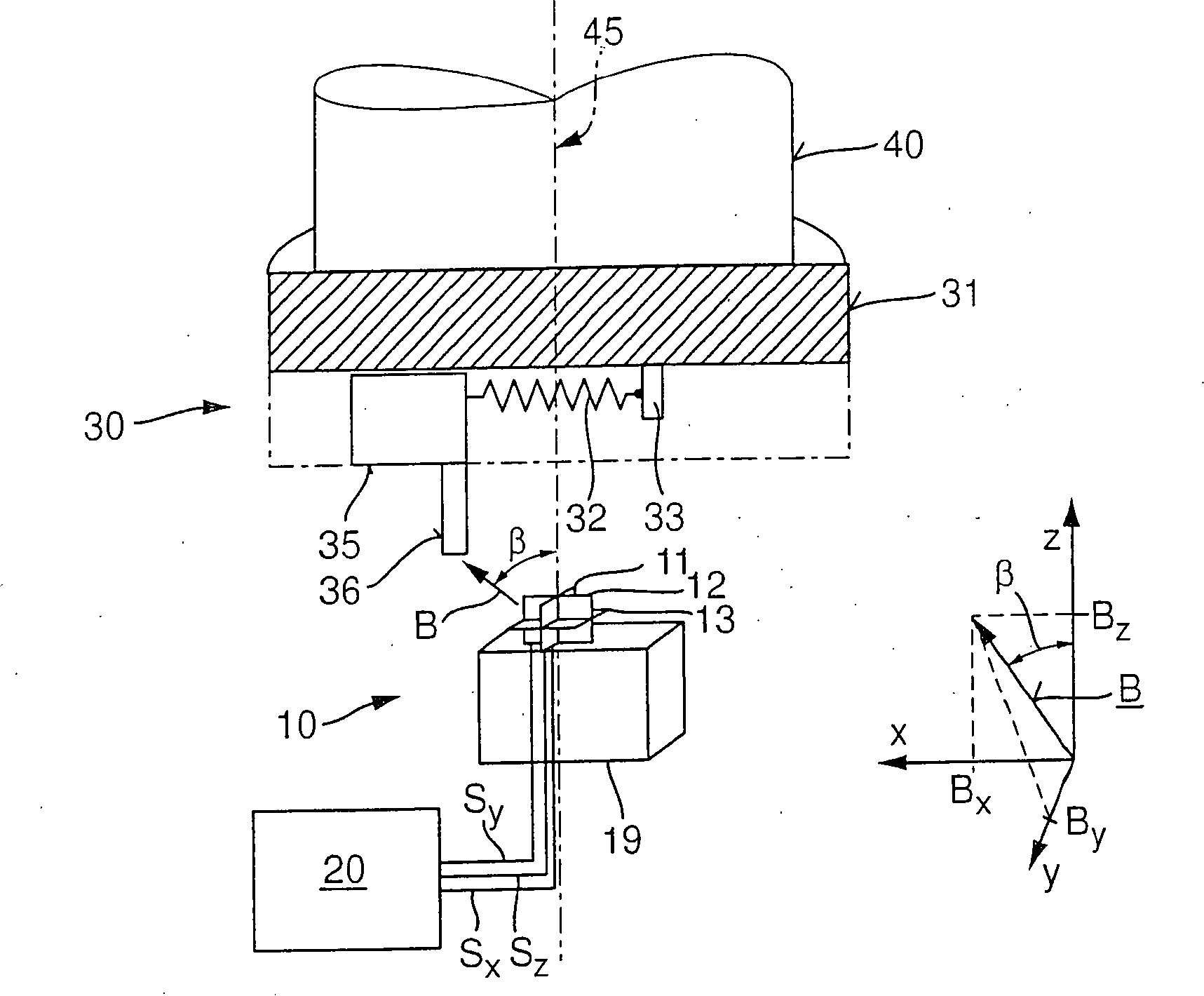
Das Messsystem arbeitet nach dem Feder-Masse-Prinzip. Der rotierbare Geber
Der Geber
Der Geber
Dabei gilt:
Dabei ist m die Masse des Masseelements
Und für diesen Fall gilt:
Somit ist der Abstand r proportional zur Winkelgeschwindigkeit ω. Je nach gewünschtem Messbereich kann der Abstand r und die Längenänderung d voneinander abweichen. Beispielsweise wird das Federelement
Der erste Magnetfeldsensor
Im Ausführungsbeispiel der
Das Magnetfeld wird durch den magnetisch leitfähigen Pin
Wie im Folgenden erläutert, ist die Magnetfeldsensoranordnung
Durch die drei Komponenten Bx, By, Bz kann der Magnetfeldvektor B und damit der Winkel β zwischen dem Magnetfeldvektor B und der Drehachse
Die Auswertungsschaltung
Die Auswertungsschaltung
Die Erfindung ist nicht auf die dargestellten Ausgestaltungsvarianten der
BezugszeichenlisteLIST OF REFERENCE NUMBERS
- 1010
- MagnetfeldsensoranordnungMagnetic field sensor arrangement
- 11, 12, 1311, 12, 13
- Magnetfeldsensor, HallsensorMagnetic field sensor, Hall sensor
- 1919
- Magnetmagnet
- 2020
- Auswertungsschaltungevaluation circuit
- 3030
- Gebergiver
- 3131
- Trägercarrier
- 3232
- Federelement, SpiralfederSpring element, spiral spring
- 3333
- Befestigungspunktattachment point
- 3535
- Masseelementmass element
- 3636
- magnetisch leitfähiges Material, Pinmagnetically conductive material, pin
- 3939
- Linearführunglinear guide
- 4040
- Wellewave
- 4545
- Achseaxis
- BB
- Magnetfeldvektormagnetic field vector
- Bx, By, Bz B x , B y , B z
- Komponente des MagnetfeldvektorsComponent of the magnetic field vector
- Sx, Sy, Sz S x , S y , S z
- Messsignalmeasuring signal
- x, y, zx, y, z
- Raumrichtungspatial direction
- β, φβ, φ
- Winkelangle
ZITATE ENTHALTEN IN DER BESCHREIBUNG QUOTES INCLUDE IN THE DESCRIPTION
Diese Liste der vom Anmelder aufgeführten Dokumente wurde automatisiert erzeugt und ist ausschließlich zur besseren Information des Lesers aufgenommen. Die Liste ist nicht Bestandteil der deutschen Patent- bzw. Gebrauchsmusteranmeldung. Das DPMA übernimmt keinerlei Haftung für etwaige Fehler oder Auslassungen.This list of the documents listed by the applicant has been generated automatically and is included solely for the better information of the reader. The list is not part of the German patent or utility model application. The DPMA assumes no liability for any errors or omissions.
Zitierte PatentliteraturCited patent literature
- EP 0188433 [0003] EP 0188433 [0003]
- DE 3018496 [0004] DE 3018496 [0004]
- DE 4133679 A1 [0005] DE 4133679 A1 [0005]
- DE 4109217 A1 [0006] DE 4109217 A1 [0006]
- DE 102998060191 A [0007] DE 102998060191 A [0007]
- DE 3520928 A1 [0007] DE 3520928 A1 [0007]
Claims (8)
Priority Applications (1)
| Application Number | Priority Date | Filing Date | Title |
|---|---|---|---|
| DE102013021693.1A DE102013021693B4 (en) | 2013-01-09 | 2013-12-20 | measuring system |
Applications Claiming Priority (3)
| Application Number | Priority Date | Filing Date | Title |
|---|---|---|---|
| DE102013000166 | 2013-01-09 | ||
| DE102013000166.8 | 2013-01-09 | ||
| DE102013021693.1A DE102013021693B4 (en) | 2013-01-09 | 2013-12-20 | measuring system |
Publications (2)
| Publication Number | Publication Date |
|---|---|
| DE102013021693A1 true DE102013021693A1 (en) | 2014-07-10 |
| DE102013021693B4 DE102013021693B4 (en) | 2015-12-31 |
Family
ID=51019132
Family Applications (1)
| Application Number | Title | Priority Date | Filing Date |
|---|---|---|---|
| DE102013021693.1A Active DE102013021693B4 (en) | 2013-01-09 | 2013-12-20 | measuring system |
Country Status (2)
| Country | Link |
|---|---|
| US (1) | US9322637B2 (en) |
| DE (1) | DE102013021693B4 (en) |
Cited By (2)
| Publication number | Priority date | Publication date | Assignee | Title |
|---|---|---|---|---|
| CN106110982A (en) * | 2016-08-08 | 2016-11-16 | 王娟 | A kind of stirrer |
| DE102016015057B3 (en) | 2016-12-17 | 2018-06-21 | Tdk-Micronas Gmbh | measuring system |
Families Citing this family (4)
| Publication number | Priority date | Publication date | Assignee | Title |
|---|---|---|---|---|
| US9316477B1 (en) * | 2014-10-01 | 2016-04-19 | Hsin-Hui Wu | Digital angle finder |
| CN106290958A (en) * | 2016-08-05 | 2017-01-04 | 安庆庆荣企业管理咨询有限责任公司 | Measure device and its operational approach of horizontal direction high-speed moving object rotating speed |
| TWI718365B (en) * | 2017-05-09 | 2021-02-11 | 漢辰科技股份有限公司 | Wafer charges monitoring |
| US10837844B2 (en) * | 2017-09-18 | 2020-11-17 | Apple Inc. | Haptic engine having a single sensing magnet and multiple hall-effect sensors |
Citations (7)
| Publication number | Priority date | Publication date | Assignee | Title |
|---|---|---|---|---|
| DE3018496A1 (en) | 1980-05-14 | 1981-11-19 | Walter Dipl.-Ing. Dr.-Ing. 8012 Ottobrunn Mehnert | METHOD AND DEVICE FOR MEASURING AN ANGLE |
| DE3520928A1 (en) | 1984-06-12 | 1985-12-12 | Voest-Alpine Friedmann GmbH, Linz | Rotational speed sensor |
| EP0188433A1 (en) | 1984-06-27 | 1986-07-30 | Bosch Gmbh Robert | Device for detecting the angular position of a rotary member. |
| US4713654A (en) * | 1986-03-03 | 1987-12-15 | Sweany Ralph S | Shaft speed monitor |
| DE4109217A1 (en) | 1991-03-21 | 1992-04-23 | Bosch Gmbh Robert | Acceleration sensor with damped spring-mass system - has helical spring wound round bearing pin, protects spring from breaking under excess acceleration |
| DE4133679A1 (en) | 1991-10-11 | 1993-04-22 | Bosch Gmbh Robert | METHOD FOR ADAPTING MECHANICAL TOLERANCES OF A SENSOR WHEEL |
| DE102008060191A1 (en) | 2008-11-28 | 2010-06-10 | Imc Messsysteme Gmbh | Measuring device for detecting rotary motion of shaft, has accumulator comprising mechanical-electrical converter rotated with shaft, where converter comprises seismic mass, and circuit device rotated with shaft and containing radio unit |
Family Cites Families (4)
| Publication number | Priority date | Publication date | Assignee | Title |
|---|---|---|---|---|
| DE10334869B3 (en) * | 2003-07-29 | 2004-09-16 | Tech3 E.K. | Rotation angle sensor has a rotating shaft with attached permanent magnets, with angular measurements based on both axial displacement of the shaft and sinusoidal and cosinusoidal signals generated by it |
| DE102008059401A1 (en) * | 2008-11-27 | 2010-06-10 | Micronas Gmbh | Semiconductor chip and method for generating pulse edges that are synchronously associated with the movement of a mechanical part |
| EP2354769B1 (en) * | 2010-02-03 | 2015-04-01 | Micronas GmbH | Angle encoder and method for determining an angle between a sensor assembly and a magnetic field |
| US8797024B2 (en) * | 2011-02-01 | 2014-08-05 | Infineon Technologies Ag | Sensor |
-
2013
- 2013-12-20 DE DE102013021693.1A patent/DE102013021693B4/en active Active
-
2014
- 2014-01-09 US US14/151,391 patent/US9322637B2/en active Active
Patent Citations (7)
| Publication number | Priority date | Publication date | Assignee | Title |
|---|---|---|---|---|
| DE3018496A1 (en) | 1980-05-14 | 1981-11-19 | Walter Dipl.-Ing. Dr.-Ing. 8012 Ottobrunn Mehnert | METHOD AND DEVICE FOR MEASURING AN ANGLE |
| DE3520928A1 (en) | 1984-06-12 | 1985-12-12 | Voest-Alpine Friedmann GmbH, Linz | Rotational speed sensor |
| EP0188433A1 (en) | 1984-06-27 | 1986-07-30 | Bosch Gmbh Robert | Device for detecting the angular position of a rotary member. |
| US4713654A (en) * | 1986-03-03 | 1987-12-15 | Sweany Ralph S | Shaft speed monitor |
| DE4109217A1 (en) | 1991-03-21 | 1992-04-23 | Bosch Gmbh Robert | Acceleration sensor with damped spring-mass system - has helical spring wound round bearing pin, protects spring from breaking under excess acceleration |
| DE4133679A1 (en) | 1991-10-11 | 1993-04-22 | Bosch Gmbh Robert | METHOD FOR ADAPTING MECHANICAL TOLERANCES OF A SENSOR WHEEL |
| DE102008060191A1 (en) | 2008-11-28 | 2010-06-10 | Imc Messsysteme Gmbh | Measuring device for detecting rotary motion of shaft, has accumulator comprising mechanical-electrical converter rotated with shaft, where converter comprises seismic mass, and circuit device rotated with shaft and containing radio unit |
Cited By (2)
| Publication number | Priority date | Publication date | Assignee | Title |
|---|---|---|---|---|
| CN106110982A (en) * | 2016-08-08 | 2016-11-16 | 王娟 | A kind of stirrer |
| DE102016015057B3 (en) | 2016-12-17 | 2018-06-21 | Tdk-Micronas Gmbh | measuring system |
Also Published As
| Publication number | Publication date |
|---|---|
| DE102013021693B4 (en) | 2015-12-31 |
| US9322637B2 (en) | 2016-04-26 |
| US20140191749A1 (en) | 2014-07-10 |
Similar Documents
| Publication | Publication Date | Title |
|---|---|---|
| DE102013021693B4 (en) | measuring system | |
| EP2965043B1 (en) | Magnetic linear or rotary encoder | |
| DE102012202634A1 (en) | Sensor arrangement for detecting e.g. steering angle of rotary component e.g. steering column in vehicle, has sensor that is provided to determine distance traveled by transmitter which represents rotational angle of rotary component | |
| DE102008045000A1 (en) | Rotation detection sensor | |
| EP1873534B1 (en) | Device for contactless determination of rotation and/or position of an object having an encoder | |
| DE102012202639A1 (en) | Sensor arrangement i.e. steering angle sensor, for detection of steering angle at gear wheel in vehicle, has sensor determining covered distance of measuring element, where covered distance represents rotational angle of rotary component | |
| DE102011012601A1 (en) | Force measuring system, method for detecting forces and moments on a rotating body and wind tunnel with a arranged therein and at least one propeller having model with a force measuring system | |
| DE112009000497T5 (en) | Origin position signal detector | |
| DE102015102013A1 (en) | Sensor device with a torque sensor device and an incremental sensor device and motor vehicle with such a sensor device | |
| DE4030229A1 (en) | ANGLE ENCODER | |
| DE102004010948B4 (en) | Angle measuring device | |
| DE10348887A1 (en) | Scanner head for measuring coordinates of surface of solid object has movable pin with ball end connected to magnet and Hall element | |
| DE102009055275A1 (en) | Sensor arrangement for combined speed-torque detection | |
| DE4129344A1 (en) | DEVICE FOR DETECTING THE TURNING ANGLE OF TWO ROTATING PARTS | |
| DE102013103445A1 (en) | Magnetic linear or rotary encoder | |
| DE3824535A1 (en) | MEASURING DEVICE FOR DETERMINING A TURNING ANGLE | |
| DE102013221943A1 (en) | Sensor system for speed measurement with a pole wheel with linearized magnetic field | |
| DE10258846A1 (en) | Rotation angle measurement arrangement has a magnetic encoder wheel and sensor that detects a tangential field component whenever a tooth passes by it or is below it | |
| DE102014208658A1 (en) | Sensor arrangement for detecting angles of rotation on a rotating component in a vehicle | |
| DE4213507C2 (en) | Device for the contactless measurement of the axial position of a rotating body | |
| DE10250319A1 (en) | Device for determining the rotation of a shaft comprises a shaft, a transmitting magnet arranged on the surface of a front side of the shaft or integrated in the region of the surface of the front side, and a GMR sensor element | |
| DE102017115916A1 (en) | Method for determining path signals of a magnetic measuring system | |
| DE102012221327A1 (en) | Sensor device for use in sensor system for determining rotational characteristic of rotating element, has transmitter wheel connected with rotating element, where transmitter wheel has multiple magnetic event detectors | |
| DE2058834C3 (en) | Device for determining the top dead center position of the piston of an internal combustion engine belonging to a motor vehicle | |
| DE102016217693A1 (en) | Apparatus and method for measuring a rotational movement of a rotatable component, in particular a rotational direction |
Legal Events
| Date | Code | Title | Description |
|---|---|---|---|
| R012 | Request for examination validly filed | ||
| R016 | Response to examination communication | ||
| R016 | Response to examination communication | ||
| R018 | Grant decision by examination section/examining division | ||
| R079 | Amendment of ipc main class |
Free format text: PREVIOUS MAIN CLASS: G01P0003440000 Ipc: G01P0003487000 |
|
| R020 | Patent grant now final | ||
| R081 | Change of applicant/patentee |
Owner name: TDK-MICRONAS GMBH, DE Free format text: FORMER OWNER: MICRONAS GMBH, 79108 FREIBURG, DE |
|
| R082 | Change of representative |
Representative=s name: KOCH-MUELLER PATENTANWALTSGESELLSCHAFT MBH, DE |