Die vorliegende Erfindung betrifft ein Elektronenmikroskop.The present invention relates to an electron microscope.
Das Elektronenmikroskop ist ein wertvolles Hilfsmittel in der Materialanalyse. Neben der vergrößernden Abbildung einer Materialprobe auf einen ortsauflösenden Bilddetektor wie im konventionellen Transmissionselektronenmikroskop (TEM), wird die analytische Elektronenmikroskopie auch dazu eingesetzt, eine Verteilung von Streuwinkeln, welche Elektronen beim Durchsetzen der Materialprobe erfahren, zu untersuchen, d. h. ein Beugungsbild der Materialprobe zu analysieren.The electron microscope is a valuable tool in material analysis. Besides magnifying the image of a material sample onto a spatially resolving image detector as in the conventional transmission electron microscope (TEM), analytical electron microscopy is also used to investigate a distribution of scattering angles experienced by electrons in traversing the material sample; H. to analyze a diffraction pattern of the material sample.
Herkömmliche als In-Lens-Systeme bezeichnete Elektronenmikroskope umfassen einen Elektromagneten, welcher ein magnetisches Feld erzeugt, das auf den Elektronenstrahl die Wirkung von zwei im Strahlengang hintereinander angeordneten elektronenoptischen Linsen hat. Das zu untersuchende Objekt wird von einer Objekthalterung in einer Objektebene gehaltert, welche zwischen den beiden elektronenoptischen Linsen angeordnet ist. Die im Strahlengang vor der Objektebene angeordnete elektronenoptische Linse hat die Wirkung einer Kondensorlinse, welche den Elektronenstrahl in der Objektebene fokussiert, und die im Strahlengang hinter der Objektebene angeordnete elektronenoptische Linse hat die Funktion einer Objektivlinse, welche ein vergrößertes Abbild der Objektebene erzeugt. Im Strahlengang hinter diesen beiden elektronenoptischen Linsen ist ein Projektivsystem angeordnet, welches selbst mehrere elektronenoptische Linsen umfasst und eine Beugungsebene der Objektivlinse auf einen Detektor vergrößert abbildet. Der Detektor kann eine Detektorkomponente umfassen, welches zentral auf einer optischen Achse der Objektivlinse und des Projektionssystems angeordnet ist, um Hellfeldelektronen zu detektieren, d. h. solche Elektronen, welche das Objekt im Wesentlichen ungestreut durchsetzt haben. Der Detektor kann ferner ein oder mehrere Detektorkomponenten umfassen, welche mit Abstand von der optischen Achse angeordnet sind, um Dunkelfeldelektronen zu detektieren, d. h. Elektronen, welche beim Durchsetzen des Objekts gestreut wurden. Das Raster-Elektronenmikroskop (SEM) umfasst ferner eine im Strahlengang vor der Objektebene angeordnete Ablenkeinrichtung, um den fokussierten Elektronenstrahl über die Objektebene zu scannen bzw. zu rastern, so dass für eine Vielzahl von Orten in der Objektebene Intensitäten von Hellfeldelektronen und Dunkelfeldelektronen als Rasterbilder detektiert werden können.Conventional electron microscopes, referred to as in-lens systems, comprise an electromagnet which generates a magnetic field which has on the electron beam the effect of two electron-optical lenses arranged one behind the other in the beam path. The object to be examined is held by an object holder in an object plane, which is arranged between the two electron-optical lenses. The arranged in the beam path in front of the object plane electron optical lens has the effect of a condenser lens which focuses the electron beam in the object plane, and arranged in the beam path behind the object plane electron-optical lens has the function of an objective lens, which generates an enlarged image of the object plane. In the beam path behind these two electron-optical lenses, a projective system is arranged, which itself comprises a plurality of electron-optical lenses and magnifies a diffraction plane of the objective lens magnified on a detector. The detector may include a detector component disposed centrally on an optical axis of the objective lens and the projection system to detect bright field electrons, i. H. those electrons which have passed through the object essentially unscattered. The detector may further comprise one or more detector components spaced from the optical axis to detect dark field electrons, i. H. Electrons that were scattered when passing through the object. The scanning electron microscope (SEM) further comprises a deflection device arranged in the beam path in front of the object plane in order to scan or focus the focused electron beam over the object plane so that intensities of bright field electrons and dark field electrons are detected as raster images for a multiplicity of locations in the object plane can be.
Das zur Abbildung der Beugungsebene der Objektivlinse auf den Detektor eingesetzte Projektionssystem ist elektronenoptisch ungünstig und aufwändig, da die Beugungsebene weit entfernt von den Linsen des Projektionssystems angeordnet ist, es verursacht hohe Kosten, nimmt erheblichen Raum ein und führt damit zu einer großen Länge des Strahlengangs des Elektronenmikroskops zwischen der Elektronenquelle und dem Detektor.The projection system used to image the diffraction plane of the objective lens on the detector is electronically unfavorable and expensive, since the diffraction plane is located far away from the lenses of the projection system, it involves high costs, takes up considerable space and thus leads to a large length of the beam path of the Electron microscope between the electron source and the detector.
Es ist eine Aufgabe der vorliegenden Erfindung, ein Elektronenmikroskop vorzuschlagen, welches einen vergleichsweise einfachen Aufbau hat und die Abbildung einer Beugungsebene einer Objektivlinse des Elektronenmikroskops auf einen Detektor erlaubt.It is an object of the present invention to provide an electron microscope which has a comparatively simple structure and allows imaging of a diffraction plane of an objective lens of the electron microscope onto a detector.
Gemäß Ausführungsformen der Erfindung umfasst ein Elektronenmikroskop eine Elektronenstrahlquelle zum Erzeugen eines Strahls von Elektronen mit einer vorbestimmten kinetischen Energie; einen in einem Strahlengang des Strahls von Elektronen angeordneten Detektor; einen in dem Strahlengang des Strahls von Elektronen zwischen der Elektronenstrahlquelle und dem Detektor angeordneten ersten Elektromagneten; eine Stromversorgung zum Zuführen eines einstellbaren Erregungsstromes zu dem ersten Elektromagneten; eine Objekthalterung zum Haltern eines zu untersuchenden Objekts in einer Objektebene, welche innerhalb eines von dem ersten Elektromagneten erzeugbaren Magnetfeldes angeordnet ist; wobei die Objektebene entlang des Strahlenganges relativ zu dem ersten Elektromagneten so angeordnet ist und die Stromversorgung so einstellbar ist, dass das von dem ersten Elektromagneten erzeugbare Magnetfeld auf den Strahl von Elektronen eine Wirkung von drei im Strahlengang hintereinander angeordneten elektronenoptischen Linsen aufweist, wobei eine erste Linse der drei elektronenoptischen Linsen in dem Strahlengang vor der Objektebene angeordnet ist und den von der Teilchenstrahlquelle erzeugten Strahl von Elektronen in der Objektebene fokussiert, eine zweite Linse der drei elektronenoptischen Linsen in dem Strahlengang hinter der Objektebene angeordnet ist, wobei eine Beugungsebene der zweiten Linse innerhalb des Magnetfeldes angeordnet ist, und eine dritte Linse der drei elektronenoptischen Linsen in dem Strahlengang hinter der zweiten Linse angeordnet ist und ein Bild der Beugungsebene der zweiten Linse in einem Bereich des Detektors erzeugt.According to embodiments of the invention, an electron microscope includes an electron beam source for generating a beam of electrons having a predetermined kinetic energy; a detector disposed in a beam path of the beam of electrons; a first electromagnet disposed in the beam path of the beam of electrons between the electron beam source and the detector; a power supply for supplying an adjustable excitation current to the first electromagnet; an object holder for holding an object to be examined in an object plane disposed within a magnetic field to be generated by the first electromagnet; wherein the object plane along the beam path is arranged relative to the first electromagnet and the power supply is adjustable so that the magnetic field generated by the first electromagnet on the beam of electrons has an effect of three in the beam path successively arranged electron optical lenses, wherein a first lens of the three electron optical lenses is arranged in the beam path in front of the object plane and focuses the beam of electrons generated by the particle beam source in the object plane, a second lens of the three electron optical lenses is arranged in the beam path behind the object plane, wherein a diffraction plane of the second lens within the Magnetic field is arranged, and a third lens of the three electron optical lenses is arranged in the beam path behind the second lens and generates an image of the diffraction plane of the second lens in a region of the detector.
Die erste Linse der drei elektronenoptischen Linsen hat die Funktion einer Kondensorlinse, indem sie den Elektronenstrahl in der Objektebene fokussiert, die zweite Linse der drei elektronenoptischen Linsen hat die Funktion einer Objektivlinse, welche eine Beugungsebene aufweist, und die dritte Linse der drei elektronenoptischen Linsen hat die Funktion, die Beugungsebene der Objektivlinse, welche durch die zweite Linse gebildet wird, vergrößert in eine Ebene abzubilden, welche außerhalb des ersten Elektromagneten angeordnet ist und in welcher der Detektor angeordnet ist.The first lens of the three electron optical lenses functions as a condenser lens by focusing the electron beam in the object plane, the second lens of the three electron optical lenses functions as an objective lens having a diffraction plane, and the third lens of the three electron optical lenses has Function, the diffraction plane of the objective lens, which is formed by the second lens, enlarged to image in a plane which is arranged outside of the first electromagnet and in which the detector is arranged.
Die drei elektronenoptischen Linsen werden von einem einzigen Elektromagneten bereitgestellt. Es ist möglich, die Konfiguration eines herkömmlichen Elektronenmikroskops, dessen Elektromagnet die Funktion einer Kondensorlinse und einer Objektivlinse bereitstellt, abzuwandeln, um die drei elektronenoptischen Linsen bereitzustellen. Beim herkömmlichen Elektronenmikroskop haltert der Probenhalter das Objekt in einer Objektebene, welche in etwa in der Mitte des erzeugten Magnetfelds angeordnet ist, und der Elektromagnet wird, abgestimmt auf die kinetische Energie des die Objektebene durchsetzenden Elektronenstrahls, so erregt, dass im Strahlengang vor der Objektebene die Wirkung der Kondensorlinse und im Strahlengang nach der Objektebene die Wirkung der Objektivlinse bereitgestellt wird. In der hier beschriebenen Ausführungsform ist der Probenhalter im Vergleich zum herkömmlichen Elektronenmikroskop derart abgewandelt, dass er das Objekt in einer Objektebene haltert, welche nicht in etwa in der Mitte des erzeugten Magnetfelds, sondern im Strahlengang vor der Mitte des erzeugten Magnetfelds angeordnet ist, so dass das erzeugte Magnetfeld im Strahlengang vor der Objektebene eine elektronenoptische Linse und im Strahlengang hinter der Objektebene zwei elektronenoptische Linsen bereitstellt. The three electron optical lenses are provided by a single electromagnet. It is possible to modify the configuration of a conventional electron microscope whose electromagnet provides the function of a condenser lens and an objective lens to provide the three electron optical lenses. In the conventional electron microscope, the sample holder holds the object in an object plane, which is arranged approximately in the middle of the generated magnetic field, and the electromagnet is, tuned to the kinetic energy of the object plane passing through the electron beam, so excited that in the beam path in front of the object plane Effect of the condenser lens and the beam path to the object plane, the effect of the objective lens is provided. In the embodiment described here, the sample holder is modified in comparison to the conventional electron microscope such that it holds the object in an object plane which is not arranged approximately in the center of the generated magnetic field, but in the beam path in front of the center of the generated magnetic field, so that the generated magnetic field in the beam path in front of the object plane provides an electron-optical lens and in the beam path behind the object plane two electron-optical lenses.
Gemäß beispielhaften Ausführungsformen haltert der Objekthalter das Objekt in einer Ebene, welche mehr als 1,5 mm oder mehr als 2 mm oder mehr als 3 mm vor der Mitte des Magnetfelds angeordnet ist. Ein Abstand zwischen der Ebene des Objekts und der Mitte des Magnetfeldes kann auch ein mehr als ein 0,15-faches, mehr als ein 0,20-faches oder mehr als ein 0,30-faches einer Halbwertsbreite des Magnetfeldes betragen. Hierbei ist als Mitte des Magnetfelds der Erwartungswert des Ortes, d. h. der Schwerpunkt, der Verteilung der Stärke des Magnetfelds, welches von dem ersten Elektromagneten erzeugt wird, entlang der Strahlachse bzw. der optischen Achse des Elektronenmikroskops zu verstehen. Hierbei ist ferner als Halbwertsbreite des Magnetfeldes der Abstand der beiden Orte entlang der Strahlachse des Elektronenmikroskops zu verstehen, an denen die magnetische Feldstärke die Hälfte des Maximalwertes der magnetischen Feldstärke auf der Strahlachse einnimmt. Bei einer entlang der Strahlachse symmetrischen Verteilung des magnetischen Feldstärke fällt die Mitte des Magnetfeldes mit dem Maximalwert der magnetischen Feldstärke zusammen.According to exemplary embodiments, the object holder supports the object in a plane which is more than 1.5 mm or more than 2 mm or more than 3 mm in front of the center of the magnetic field. Also, a distance between the plane of the object and the center of the magnetic field may be more than 0.15 times, more than 0.20 times, or more than 0.30 times a half width of the magnetic field. Here, as the center of the magnetic field, the expected value of the location, i. H. the center of gravity, the distribution of the strength of the magnetic field, which is generated by the first electromagnet, to understand along the beam axis and the optical axis of the electron microscope. Here, the half-width of the magnetic field is also to be understood as meaning the distance of the two locations along the beam axis of the electron microscope, at which the magnetic field strength occupies half the maximum value of the magnetic field strength on the beam axis. In a distribution of the magnetic field strength which is symmetrical along the beam axis, the center of the magnetic field coincides with the maximum value of the magnetic field strength.
Es ist somit möglich, mit einem einzigen Elektronmagneten ein vergrößertes Bild der Beugungsebene der Objektivlinse des Elektronenmikroskops in einer Ebene zu erzeugen, welche mit ausreichendem Abstand von dem ersten Elektromagneten angeordnet ist, so dass dort ein Detektor zur Detektion von Elektronen angeordnet werden kann. Ein separates Projektionssystem, wie es beim herkömmlichen Elektronenmikroskop zur Abbildung der Beugungsebene eingesetzt wird, ist somit nicht notwendig.It is thus possible to generate with a single electron magnet an enlarged image of the diffraction plane of the objective lens of the electron microscope in a plane which is arranged at a sufficient distance from the first electromagnet so that a detector for detecting electrons can be arranged there. A separate projection system, as used in the conventional electron microscope for imaging the diffraction plane, is therefore not necessary.
Gemäß beispielhaften Ausführungsformen umfasst das Elektronenmikroskop einen in dem Strahlengang des Strahls von Elektronen zwischen dem ersten Elektromagneten und dem Detektor angeordneten zweiten Elektromagneten, dessen Magnetfeld auf den Strahl von Elektronen die Wirkung einer vierten elektronenoptischen Linse aufweist, wobei die Stromversorgung dazu konfiguriert ist, durch Ändern des dem zweiten Elektronmagneten zugeführten Erregungsstroms eine Größe des Bildes der Beugungsebene der zweiten Linse auf dem Detektor zu ändern. Hierdurch ist es möglich, den Abstand von der optischen Achse, an dem Elektronen auf den Detektor treffen, welche in der Objektebene um einen bestimmten Winkel gestreut wurden, zu ändern. Umgekehrt ist es damit möglich, mit einer Detektorkomponente, welches mit einem bestimmten Abstand von der optischen Achse angeordnet ist, wahlweise Elektronen zu detektieren, welche mit verschiedenen einstellbaren Winkeln bzw. Winkelbereichen in der Objektebene gestreut wurden. Es ist hierdurch möglich, Verfahren des ”Annular Dark-Field Imaging” durchzuführen.According to exemplary embodiments, the electron microscope comprises a second electromagnet arranged in the beam path of the beam of electrons between the first electromagnet and the detector, the magnetic field of which on the beam of electrons has the effect of a fourth electron optical lens, the power supply being configured by changing the electron beam the second electron magnet supplied excitation current to change a size of the image of the diffraction plane of the second lens on the detector. This makes it possible to change the distance from the optical axis at which electrons hit the detector, which were scattered in the object plane by a certain angle. Conversely, it is thus possible with a detector component, which is arranged at a certain distance from the optical axis, optionally to detect electrons which have been scattered at different adjustable angles or angular ranges in the object plane. It is thereby possible to perform Annular Dark-Field Imaging methods.
Gemäß beispielhaften Ausführungsformen erzeugt die zweite Linse, welche die Funktion der Objektivlinse haben kann, ein Bild der Objektebene innerhalb des von dem ersten Elektronmagneten erzeugten Magnetfelds.According to exemplary embodiments, the second lens, which may have the function of the objective lens, generates an image of the object plane within the magnetic field generated by the first electron magnet.
Gemäß weiterer beispielhafter Ausführungsformen hierin ist dieses Bild der Objektebene im Strahlengang vor einer Hauptebene der dritten Linse angeordnet.According to further exemplary embodiments herein, this image of the object plane is arranged in the beam path in front of a main plane of the third lens.
Gemäß beispielhafter Ausführungsformen umfasst der Detektor eine erste Detektorkomponente, welches eine elektronensensitive Fläche aufweist, welche innerhalb eines Kreises mit einem ersten Durchmesser angeordnet ist. Der erste Durchmesser kann hierbei so auf einen Konuswinkel bzw. Öffnungswinkel des auf die Objektebene fokussierten Elektronenstrahls abgestimmt sein, dass die Elektronen, welche die Objektebene ungestreut durchsetzen, sämtlich auf die erste Detektorkomponente treffen und Elektronen, welche in der Objektebene um einen signifikanten Winkel gestreut werden, nicht auf die erste Detektorkomponente treffen, wenn der zweite Elektromagnet nicht erregt wird oder lediglich gering erregt wird, so dass die optische Wirkung der vierten elektronenoptischen Linse nicht vorhanden oder lediglich gering ist. In dieser Situation werden von der ersten Detektorkomponente Hellfeldelektronen detektiert. Wird dann die Erregung des zweiten Elektromagneten erhöht, so dass die vierte Linse eine stärkere fokussierende Wirkung bereitstellt, so treffen auch Dunkelfeldelektronen auf die erste Detektorkomponente. Je stärker der zweite Elektromagnet erregt wird, umso mehr Dunkelfeldelektronen treffen auf die erste Detektorkomponente.According to exemplary embodiments, the detector includes a first detector component having an electron-sensitive surface disposed within a circle having a first diameter. The first diameter may in this case be matched to a cone angle or opening angle of the electron beam focused on the object plane such that the electrons which pass through the object plane unscatterly strike all of the first detector component and electrons which are scattered in the object plane by a significant angle , Do not encounter the first detector component when the second electromagnet is not energized or is only slightly excited, so that the optical effect of the fourth electron-optical lens is not present or only low. In this situation, bright field electrons are detected by the first detector component. If then the excitation of the second electromagnet is increased, so that the fourth lens provides a stronger focusing effect, so Dark field electrons also hit the first detector component. The more the second electromagnet is energized, the more dark field electrons strike the first detector component.
Gemäß einer weiteren beispielhaften Ausführungsform hierin ist die elektronensensitive Fläche der ersten Detektorkomponente außerhalb eines Kreises mit einem zweiten Durchmesser angeordnet, welcher kleiner ist als der erste Durchmesser. Damit detektiert die erste Detektorkomponente Elektronen, welche innerhalb des Kreises mit dem zweiten Durchmesser auf die Bildebene der Beugungsebene treffen, nicht. Der zweite Durchmesser kann hierbei so gewählt werden, dass bei der starken Erregung, bei der Dunkelfeldelektronen auf die erste Detektorkomponente treffen, Hellfeldelektronen innerhalb des Kreises mit dem zweiten Durchmesser auf die Ebene des Bildes der Beugungsebene treffen, so dass die Hellfeldelektronen von der ersten Detektorkomponente nicht detektiert werden und somit lediglich Dunkelfeldelektronen von der ersten Detektorkomponente detektiert werden.According to another exemplary embodiment herein, the electron-sensitive surface of the first detector component is disposed outside of a circle having a second diameter which is smaller than the first diameter. Thus, the first detector component does not detect electrons which strike the image plane of the diffraction plane within the circle having the second diameter. In this case, the second diameter can be selected such that bright field electrons within the circle with the second diameter strike the plane of the image of the diffraction plane during the strong excitation, in which dark field electrons strike the first detector component, so that the bright field electrons from the first detector component do not hit are detected and thus only dark field electrons are detected by the first detector component.
Gemäß einer beispielhaften Ausführungsform hierin weist die Detektorkomponente innerhalb des Kreises mit dem zweiten Durchmesser eine Ausnehmung auf, durch welche Elektronen hindurchtreten können. Gemäß einer beispielhaften Ausführungsform hierin, ist im Strahlengang hinter der ersten Detektorkomponente ein Elektronenspektrometer angeordnet, mit welchem das Spektrum der kinetischen Energien der in das Elektronenspektrometer eintretenden Elektronen gemessen werden kann. Es ist somit möglich, mit der ersten Detektorkomponente Dunkelfeldelektronen zu detektieren und das Energiespektrum der durch die erste Detektorkomponente hindurchtretenden Hellfeldelektronen zu bestimmen.According to an exemplary embodiment herein, the detector component within the circle having the second diameter has a recess through which electrons can pass. According to an exemplary embodiment herein, an electron spectrometer is arranged in the beam path behind the first detector component with which the spectrum of the kinetic energies of the electrons entering the electron spectrometer can be measured. It is thus possible to detect dark field electrons with the first detector component and to determine the energy spectrum of the bright field electrons passing through the first detector component.
Gemäß beispielhafter Ausführungsformen umfasst der Detektor eine erste Detektorkomponente, welche eine elektronensensitive Fläche aufweist, welche innerhalb eines Kreises mit einem ersten Durchmesser angeordnet ist, und eine zweite Detektorkomponente, welches eine elektronensensitive Fläche aufweist, welche außerhalb eines Kreises mit einem dritten Durchmesser angeordnet ist, der größer oder gleich dem ersten Durchmesser ist. Hierdurch ist es möglich, mit der ersten Detektorkomponente Hellfeldelektronen zu detektieren und mit der zweiten Detektorkomponente Dunkelfeldelektronen zu detektieren.According to exemplary embodiments, the detector comprises a first detector component having an electron-sensitive surface disposed within a circle having a first diameter and a second detector component having an electron-sensitive surface disposed outside of a circle having a third diameter greater than or equal to the first diameter. This makes it possible to detect bright field electrons with the first detector component and to detect dark field electrons with the second detector component.
Gemäß beispielhafter Ausführungsformen hierin ist die elektronensensitive Fläche der zweiten Detektorkomponente innerhalb eines Kreises mit einem vierten Durchmesser angeordnet, welcher größer als der dritte Durchmesser ist, so dass die elektronensensitive Fläche der zweiten Detektorkomponente beispielsweise eine ringförmige Gestalt aufweisen kann. Die Breite des Rings, d. h. die Differenz zwischen dem vierten Durchmesser und dem dritten Durchmesser kann so gewählt sein, dass lediglich Dunkelfeldelektronen auf die zweite Detektorkomponente treffen, welche in der Objektebene um Streuwinkel gestreut wurden, welche innerhalb lediglich eines Teilbereichs der entstehenden Streuwinkel liegen. Durch Ändern der Erregung des zweiten Elektronmagneten und entsprechende Änderung der Stärke der durch den zweiten Elektromagneten bereitgestellten vierten elektronenoptischen Linse ist es somit möglich, den Bereich an Streuwinkeln von Elektronen, welche auf die zweite Detektorkomponente treffen, zu ändern. Hierdurch ist es möglich, Verfahren des ”Annular Dark-Field Imaging” durchzuführen.According to exemplary embodiments herein, the electron-sensitive surface of the second detector component is disposed within a circle having a fourth diameter greater than the third diameter, such that the electron-sensitive surface of the second detector component may be, for example, annular in shape. The width of the ring, d. H. the difference between the fourth diameter and the third diameter may be chosen so that only dark field electrons strike the second detector component, which were scattered in the object plane by scattering angles which lie within only a partial region of the resulting scattering angles. Thus, by changing the excitation of the second electron magnet and correspondingly changing the strength of the fourth electron optical lens provided by the second electromagnet, it is possible to change the range of scattering angles of electrons striking the second detector component. This makes it possible to perform "Annular Dark-Field Imaging" methods.
Gemäß beispielhafter Ausführungsformen ist die zweite Detektorkomponente im Strahlengang vor der ersten Detektorkomponente angeordnet und weist eine Ausnehmung auf, durch welche Elektronen hindurchtreten können, um auf die erste Detektorkomponente zu treffen.According to exemplary embodiments, the second detector component is arranged in the beam path in front of the first detector component and has a recess through which electrons can pass to strike the first detector component.
Gemäß beispielhafter Ausführungsformen umfasst das wenigstens einen in dem Strahlengang des Strahls von Elektronen zwischen der Elektronenstrahlquelle und dem ersten Elektromagneten angeordneten dritten Elektromagneten zur Erzeugung eines Magnetfeldes, welches auf den Strahl von Elektronen eine Wirkung wenigstens einer Kondensorlinse aufweist, welche die Elektronenstrahlquelle in eine Eingangsbildebene der ersten elektronenoptischen Linse oder in eine vordere Brennebene der ersten elektronenoptischen Linse abbildet.According to exemplary embodiments, the at least one third electromagnet arranged in the beam path of the beam of electrons between the electron beam source and the first electromagnet comprises generating a magnetic field which has on the beam of electrons an effect of at least one condenser lens which directs the electron beam source into an input image plane of the first electron optical lens or in a front focal plane of the first electron optical lens.
Ausführungsformen der Erfindung werden nachfolgend anhand von Figuren näher erläutert. Hierbei zeigt:Embodiments of the invention are explained below with reference to figures. Hereby shows:
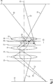
1 eine schematische Darstellung eines Strahlengangs eines Elektronenmikroskops gemäß einer ersten Ausführungsform; 1 a schematic representation of a beam path of an electron microscope according to a first embodiment;
2 eine Darstellung von Details des Strahlengangs der 1; 2 a representation of details of the beam path of 1 ;
3 eine weitere Darstellung von Details des Strahlengangs der 1; 3 another illustration of details of the beam path of 1 ;
4 eine schematische Darstellung eines Strahlengangs eines Elektronenmikroskops gemäß einer zweiten Ausführungsform in einem ersten Betriebsmodus; 4 a schematic representation of a beam path of an electron microscope according to a second embodiment in a first operating mode;
5 eine schematische Darstellung des Strahlengangs des Elektronenmikroskops der 4 in einem zweiten Betriebsmodus; 5 a schematic representation of the beam path of the electron microscope of 4 in a second mode of operation;
6 eine schematische Darstellung eines Strahlengangs eines Elektronenmikroskops gemäß einer dritten Ausführungsform in einem ersten Betriebsmodus; 6 a schematic representation of a beam path of an electron microscope according to a third embodiment in a first mode of operation;
7 eine schematische Darstellung des Strahlengangs des Elektronenmikroskops der 6 in einem zweiten Betriebsmodus; und 7 a schematic representation of the beam path of the electron microscope of 6 in a second mode of operation; and
8 eine schematische Darstellung von Elektromagneten und weiteren Komponenten, wie sie für die Realisierung der Elektronenmikroskope gemäß den 1 bis 7 einsetzbar sind. 8th a schematic representation of electromagnets and other components, as they are for the realization of the electron microscopes according to the 1 to 7 can be used.
1 zeigt eine schematische Darstellung eines Strahlengangs eines Elektronenmikroskops 1. Das Elektronenmikroskop 1 umfasst eine Elektronenstrahlquelle 3, welche einen divergenten Elektronenstrahl 5 erzeugt. Der Elektronenstrahl 5 durchsetzt wenigstens eine Kondensorlinse 7, von welcher er fokussiert wird, um in einer Ebene 10 einen Crossover 9 bzw. ein Bild der Elektronenstrahlquelle 3 zu erzeugen. Die Ebene 10 ist eine Eingangsbildebene einer nachfolgend noch detailliert beschriebenen Linse 11. Die Kondensorlinse 7 kann durch ein von einem Elektromagneten bereitgestelltes Magnetfeld erzeugt werden und könnte alternativ auch ein Bild der Elektronenstrahlquelle 3 in einer vorderen Brennebene 59 (siehe 2) der Linse 11 erzeugen. Im Strahlengang hinter dem Crossover 9 sind nacheinander drei elektronenoptische Linsen 11, 13 und 15 angeordnet, welche durch ein Magnetfeld eines ersten Elektromagneten erzeugt werden, wie dies nachfolgend erläutert wird. Im Strahlengang hinter der Linse 15 ist eine vierte elektronenoptische Linse 17 angeordnet, welche durch ein Magnetfeld eines weiteren Elektromagneten erzeugt wird. 1 shows a schematic representation of a beam path of an electron microscope 1 , The electron microscope 1 includes an electron beam source 3 which gives a divergent electron beam 5 generated. The electron beam 5 passes through at least one condenser lens 7 from which he is focused to in one plane 10 a crossover 9 or an image of the electron beam source 3 to create. The level 10 is an input image plane of a lens described in detail below 11 , The condenser lens 7 may be generated by a magnetic field provided by an electromagnet and, alternatively, could also be an image of the electron beam source 3 in a front focal plane 59 (please refer 2 ) of the lens 11 produce. In the beam path behind the crossover 9 are successively three electron-optical lenses 11 . 13 and 15 arranged, which are generated by a magnetic field of a first electromagnet, as will be explained below. In the beam path behind the lens 15 is a fourth electron optical lens 17 arranged, which is generated by a magnetic field of another electromagnet.
Zwischen den beiden Linsen 11 und 13 ist eine Objektebene 19 angeordnet, in welcher ein in 1 nicht dargestellter Probenhalter ein zu untersuchendes Objekt haltert. Die Linse 11 hat die Funktion einer Kondensorlinse und fokussiert den Elektronenstrahl 5 in der Objektebene 19, indem sie den Elektronenstrahl 5 in der Objektebene 19 an einem Ort 21 fokussiert, wozu die Linse 11 den Crossover 9 in die Objektebene 19 abbildet und dort ein weiteres Bild der Elektronenstrahlquelle 3 erzeugt. Der Ort 21 liegt auf einer optischen Achse 23, entlang der die Elektronenstrahlquelle 3 und die Linsen 7, 11, 13 und 15 zentriert sind. Ein Elektronendeflektor 25 ist im Strahlengang vor der Objektebene 19 angeordnet, um den Elektronenstrahl 5 abzulenken, so dass der Ort 21, an dem der Elektronenstrahl 5 in der Objekteben 19 fokussiert wird, über die Objektebene 19 gescannt werden kann. In der 1 sind exemplarisch zwei abgelenkte Elektronenstrahlen dargestellt, welche an den Orten 21' und 21'' in der Objektebene 19 fokussiert sind.Between the two lenses 11 and 13 is an object plane 19 arranged in which a in 1 Unillustrated sample holder supports an object to be examined. The Lens 11 has the function of a condenser lens and focuses the electron beam 5 in the object plane 19 by taking the electron beam 5 in the object plane 19 in one place 21 focused, what the lens 11 the crossover 9 into the object plane 19 depicts and there another image of the electron beam source 3 generated. The place 21 lies on an optical axis 23 along which the electron beam source 3 and the lenses 7 . 11 . 13 and 15 are centered. An electron deflector 25 is in the beam path in front of the object plane 19 arranged to the electron beam 5 distract, leaving the place 21 at which the electron beam 5 in the objectben 19 is focused, over the object plane 19 can be scanned. In the 1 are exemplified two deflected electron beams, which at the places 21 ' and 21 '' in the object plane 19 are focused.
Die Linse 13 bildet die Objektebene 19 in eine Ebene 25 ab und weist selbst eine hintere Brennebene bzw. Beugungsebene 27 auf.The Lens 13 forms the object plane 19 in a plane 25 and even has a rear focal plane or diffraction plane 27 on.
Die Linse 15 bildet die Beugungsebene 27 vergrößert in eine Ebene 29 ab, welche im Strahlengang hinter der Linse 17 angeordnet ist und in welcher oder nahe welcher ein Detektor 31 angeordnet ist. Der Detektor 31 umfasst eine zentrale erste Detektorkomponente 33 und eine die erste Detektorkomponente 33 ringförmig umgebende zweite Detektorkomponente 35.The Lens 15 forms the diffraction plane 27 enlarged into a plane 29 which is in the beam path behind the lens 17 is arranged and in which or near which a detector 31 is arranged. The detector 31 includes a central first detector component 33 and a first detector component 33 annular surrounding second detector component 35 ,
Die erste Detektorkomponente 33 weist eine elektronensensitive Fläche 37 auf, welche innerhalb eines Kreises mit einem Durchmesser D1 angeordnet ist. Die zweite Detektorkomponente 35 weist eine elektronensensitive Fläche 39 auf, welche außerhalb eines Kreises mit einem Durchmesser D3 angeordnet ist.The first detector component 33 has an electron-sensitive surface 37 which is arranged within a circle with a diameter D1. The second detector component 35 has an electron-sensitive surface 39 which is arranged outside a circle with a diameter D3.
Im Strahlengang vor der Objektebene 19 ist eine Blende 41 mit einer kreisrunden Ausnehmung vorgesehen, durch welche ein Konvergenzwinkel bzw. Öffnungswinkel des auf die Objektebene 19 fokussierten Elektronenstrahls 5 definiert wird. Der Durchmesser der Ausnehmung der Blende 41 kann einstellbar sein, oder es können mehrere Blenden 41 mit verschiedenen Durchmessern ihrer Öffnungen vorgesehen sein, welche wahlweise in den Strahlengang eingebracht werden können, um den Öffnungswinkel des in der Objektebene 19 fokussierten Strahls zu ändern.In the beam path in front of the object plane 19 is a blind 41 provided with a circular recess, through which a convergence angle or opening angle of the object plane 19 focused electron beam 5 is defined. The diameter of the recess of the aperture 41 can be adjustable, or it can have multiple apertures 41 be provided with different diameters of their openings, which can be optionally introduced into the beam path to the opening angle of the object in the plane 19 to change the focused beam.
Der Durchmesser D1 der elektronensensitiven Fläche 37 der ersten Detektorkomponente 33 ist auf den Öffnungswinkel des auf die Objektebene 19 fokussierten Elektronenstrahls 5 so abgestimmt, dass die Elektronen des Elektronenstrahls 5, welche an dem in der Objektebene 19 angeordneten Objekt nicht gestreut werden, sämtlich auf die elektronensensitive Fläche 37 der ersten Detektorkomponente 33 treffen. Die erste Detektorkomponente 33 wirkt somit als ein Hellfelddetektor des Elektronenmikroskops 1.The diameter D1 of the electron-sensitive surface 37 the first detector component 33 is at the opening angle of the object plane 19 focused electron beam 5 tuned so that the electrons of the electron beam 5 , which at the in the object level 19 arranged object can not be scattered, all on the electron-sensitive surface 37 the first detector component 33 to meet. The first detector component 33 thus acts as a brightfield detector of the electron microscope 1 ,
Elektronen des Elektronenstrahls 5, welche an dem in der Objektebene 19 angeordneten Objekt um einen signifikanten Winkel gestreut werden, treffen auf die elektronensensitive Fläche 39 der zweiten Detektorkomponente 35, so dass dieser als ein Dunkelfelddetektor wirkt.Electrons of the electron beam 5 , which at the in the object level 19 arranged object scattered by a significant angle, hit the electron-sensitive surface 39 the second detector component 35 so that it acts as a dark field detector.
Der durch die drei Linsen 11, 13 und 15 zwischen den Ebenen 10 und 29 bereitgestellte Strahlengang wird nachfolgend anhand der 2 näher erläutert.The one through the three lenses 11 . 13 and 15 between the levels 10 and 29 provided beam path is described below with reference to 2 explained in more detail.
In 2 stellt eine Linie 51 einen Axialstrahl dar, der in der Ebene 10 auf der optischen Achse 23 und unter einem Winkel zur optischen Achse 23 startet. Da die als Kondensorlinse wirkende Linse 11 die Ebene 10 in die Objektebene 19 abbildet, schneidet der Strahl 51 die optische Achse 23 in der Objektebene 19. Die Objektivlinse 13 lenkt den Strahl 51 nach dem Durchsetzen der Objektebene 19 wieder hin zur optischen Achse 23 ab, so dass er die optische Achse 23 wieder in der Ebene 25 schneidet, welche damit eine Bildebene der Objektebene 19 ist, in welcher ein durch einen Pfeil 53 repräsentiertes Bild der Objektebene 19 entsteht.In 2 represents a line 51 an axial jet that is in the plane 10 on the optical axis 23 and at an angle to the optical axis 23 starts. Because the lens acting as a condenser lens 11 the level 10 into the object plane 19 The beam cuts 51 the optical axis 23 in the object plane 19 , The objective lens 13 directs the beam 51 after enforcing the object plane 19 back to the optical axis 23 off so he's the optical axis 23 back in the plane 25 which thus forms an image plane of the object plane 19 is in which one by an arrow 53 represented image of the object plane 19 arises.
Die Bildebene 25 ist mit geringem Abstand vor einer Hauptebene 55 der Linse 15 angeordnet, so dass der Strahl 51 die Linse 15 nahe der optischen Achse 23 durchsetzt und somit von der Linse 15 nur geringfügig abgelenkt wird.The picture plane 25 is a short distance away from a main level 55 the lens 15 arranged so that the beam 51 the Lens 15 near the optical axis 23 interspersed and thus from the lens 15 only slightly distracted.
Eine Linie 57 in 2 stellt einen Feldstrahl dar, welcher in der Ebene 10 mit Abstand von der optischen Achse unter einem solchen Winkel startet, dass er die optische Achse 23 in einer vorderen Brennebene 59 der Kondensorlinse 11 schneidet. Damit durchsetzt der Strahl 57 die Objektebene 19 parallel zur optischen Achse 23 und wird von der Objektivlinse 13 so abgelenkt, dass er die optische Achse 23 wieder in der hinteren Brennebene bzw. Beugungsebene 27 der Objektivlinse 13 schneidet. Die Linse 15 bildet die Beugungsebene 27 der Objektivlinse 13 in die Ebene 29 ab, so dass der Strahl 57 durch die Linse 15 so abgelenkt wird, dass er die optische Achse 23 wiederum in der Ebene 29 schneidet.A line 57 in 2 represents a field ray which is in the plane 10 starting at a distance from the optical axis at such an angle that it is the optical axis 23 in a front focal plane 59 the condenser lens 11 cuts. This intersperses the beam 57 the object plane 19 parallel to the optical axis 23 and is from the objective lens 13 so distracted that he's the optical axis 23 again in the back focal plane or diffraction plane 27 the objective lens 13 cuts. The Lens 15 forms the diffraction plane 27 the objective lens 13 into the plane 29 off, so the beam 57 through the lens 15 is deflected so that it is the optical axis 23 turn in the plane 29 cuts.
Eine Linie 61 in 2 stellt einen weiteren Feldstrahl dar, welcher in der Ebene 10 von dem gleichen Punkt startet wie der Feldstrahl 57. Allerdings startet der Feldstrahl 61 von der Ebene 10 unter einem Winkel, der verschieden ist von dem Winkel, unter dem der Feldstrahl 57 von der optischen Achse 10 startet. Der Strahl 61 schneidet den Strahl 57 in der Objektebene 19, da die Kondensorlinse 11 die Ebene 10 in die Objektebene 19 abbildet. Ein weiterer Schnittpunkt zwischen den Feldstrahlen 57 und 61 ergibt sich in der Ebene 25, wohin die Objektivlinse 13 die Objektebene 19 abbildet. Aufgrund des Winkels zwischen den Strahlen 57 und 61 in der Ebene 25 und der Ablenkung durch die Linse 15 landen die Strahlen 51 und 61 in der Ebene 29 an verschiedenen Orten. Werden die Strahlen 51 und 61 ausgehend von der Ebene 29 entgegen der Strahlrichtung durch die Linse 15 hindurch geradlinig verlängert, wie dies in 2 mit gestrichelten Linien dargestellt ist, so schneiden sie sich in einer Ebene 63, so dass dort ein virtuelles Bild der Objektebene 19 entsteht, welches in 2 durch einen gestrichelten Pfeil 65 dargestellt ist. Das reelle Bild 53 der Objektebene 19 entsteht in der Ebene 25, wie dies vorangehend erläutert wurde.A line 61 in 2 represents another field beam which is in the plane 10 starts from the same point as the field beam 57 , However, the field beam starts 61 from the plane 10 at an angle that is different from the angle below which the field beam 57 from the optical axis 10 starts. The beam 61 cuts the beam 57 in the object plane 19 because the condenser lens 11 the level 10 into the object plane 19 maps. Another intersection between the field rays 57 and 61 arises in the plane 25 where to the objective lens 13 the object plane 19 maps. Due to the angle between the rays 57 and 61 in the plane 25 and the deflection through the lens 15 the rays end up 51 and 61 in the plane 29 at different places. Become the rays 51 and 61 starting from the plane 29 against the beam direction through the lens 15 extends straight through, as in 2 shown with dashed lines, so they intersect in a plane 63 , so that there is a virtual image of the object plane 19 arises, which in 2 by a dashed arrow 65 is shown. The real picture 53 the object level 19 arises in the plane 25 as previously explained.
In der vorangehend beschriebenen Ausführungsform sind die Elektromagneten, welche die Kondensorlinse 7 bereitstellen, so erregt, dass die Kondensorlinse 7 die Elektronenquelle 3 in die Ebene 10 abbildet. In einer von dieser Erregung der Elektromagneten abweichenden alternativen Erregung der Elektromagneten bildet die Kondensorlinse 7 die Elektronenquelle in die vordere Brennebene 59 der Linse 11 ab. Es entstehen dann bei kristallinen Proben in den Ebenen 27 und 29 jeweils ein diskretes Beugungsbild mit scharfen Reflexen (Bragg Diffraction). Eine in der Ebene 10 angeordnete Blende kann als eine Selektionsblende für den beugenden Bereich wirken.In the embodiment described above, the electromagnets are the condenser lens 7 deploy, so excited that the condenser lens 7 the electron source 3 into the plane 10 maps. In a deviating from this excitation of the electromagnet alternative excitation of the electromagnets forms the condenser lens 7 the electron source in the front focal plane 59 the lens 11 from. It then arises with crystalline samples in the planes 27 and 29 each a discrete diffraction pattern with sharp reflections (Bragg Diffraction). One in the plane 10 arranged aperture can act as a selection aperture for the diffractive region.
3 ist eine schematische Darstellung, um den Strahlengang zwischen den Ebenen 10 und 29 weiter zu erläutern. Die in den 1 und 2 gezeigten drei Linsen 11, 13 und 15 werden durch das Magnetfeld eines einzigen Elektromagneten bereitgestellt. 3 zeigt schematisch ein Paar von Polstücken 71 und 73 des Elektromagneten, welche, gesehen in Richtung der optischen Achse 23 mit einem Abstand s voneinander angeordnet sind. Zwischen den Polstücken 71 und 73 wird von dem Elektromagneten das Magnetfeld erzeugt. Die Stärke des Magnetfelds B in Abhängigkeit von einem Ort z entlang der optischen Achse 23 ist in 3 durch eine Linie B(z) in einem Diagramm dargestellt. Aufgrund der Symmetrie des Elektromagneten und insbesondere der Polstücke 71 und 73 weist die Stärke des Magnetfelds B(z) ein Maximum auf, welches in der Mitte zwischen den beiden Polstücken 71 und 73 angeordnet ist, wobei der Verlauf der Stärke des Magnetfelds B(z) symmetrisch zu einer Mittelebene zwischen den Polstücken 71 und 73 ist. Auch wenn der Verlauf der Stärke des Magnetfelds B(z) nicht symmetrisch zur Mittelebene der beiden Polstücke 71 und 73 wäre, kann ein Mittelpunkt bzw. Schwerpunkt des Feldes bestimmt werden, indem der Erwartungswert des Ortes für die Funktion B(z), d. h. der Schwerpunkt des Magnetfelds B(z), durch Integration entlang der optischen Achse 23 bestimmt wird. In der 3 sind der Axialstrahl 51 und der Feldstrahl 57 dargestellt, wobei diese Strahlen durch das Magnetfeld B(z) abgelenkt werden. Der Axialstrahl 51 schneidet die optische Achse 23 in der Objektebene 19, in welcher das Objekt anzuordnen ist, damit das Magnetfeld B(z) auf den Elektronenstrahl die Wirkung der in 2 dargestellten Linsen 11, 13 und 15 hat. Es ist ersichtlich, dass die Objektebene 19 vor der Mittelebene 75 des Magnetfelds und mit einem Abstand d von dieser angeordnet ist. 3 is a schematic representation of the beam path between the planes 10 and 29 to explain further. The in the 1 and 2 shown three lenses 11 . 13 and 15 are provided by the magnetic field of a single electromagnet. 3 schematically shows a pair of pole pieces 71 and 73 of the electromagnet, which, seen in the direction of the optical axis 23 are arranged at a distance s from each other. Between the pole pieces 71 and 73 the magnetic field is generated by the electromagnet. The strength of the magnetic field B as a function of a location z along the optical axis 23 is in 3 represented by a line B (z) in a diagram. Due to the symmetry of the electromagnet and in particular of the pole pieces 71 and 73 has the strength of the magnetic field B (z) a maximum, which is in the middle between the two pole pieces 71 and 73 is arranged, wherein the course of the strength of the magnetic field B (z) symmetrical to a median plane between the pole pieces 71 and 73 is. Even if the course of the strength of the magnetic field B (z) is not symmetrical to the center plane of the two pole pieces 71 and 73 If desired, a centroid of the field may be determined by taking the expected value of the location for the function B (z), that is, the center of gravity of the magnetic field B (z), by integration along the optical axis 23 is determined. In the 3 are the axial jet 51 and the field beam 57 shown, wherein these rays are deflected by the magnetic field B (z). The axial jet 51 cuts the optical axis 23 in the object plane 19 in which the object is to be arranged, so that the magnetic field B (z) on the electron beam, the effect of in 2 illustrated lenses 11 . 13 and 15 Has. It can be seen that the object plane 19 in front of the middle plane 75 of the magnetic field and at a distance d from this is arranged.
In einem Ausführungsbeispiel beträgt der Abstand s 15 mm, der Abstand d 3,21 mm und das in der Ebene 75 erzeugte maximale Magnetfeld weist eine Stärke von 0,75 Tesla auf für einen Elektronenstrahl der kinetischen Energie 100 keV.In one embodiment, the distance s is 15 mm, the distance d is 3.21 mm and in the plane 75 maximum magnetic field generated has a strength of 0.75 Tesla for a kinetic energy electron beam of 100 keV.
In einem weiteren Ausführungsbeispiel beträgt der Abstand s 10 mm, der Abstand d 2,26 mm und das in der Ebene 75 erzeugte maximale Magnetfeld weist eine Stärke von 1,124 Tesla auf für einen Elektronenstrahl der kinetischen Energie 100 keV.In a further embodiment, the distance s is 10 mm, the distance d is 2.26 mm and that in the plane 75 maximum magnetic field generated has a magnitude of 1.124 Tesla for a kinetic energy electron beam of 100 keV.
Vorangehend wurde anhand der 2 und 3 im Wesentlichen die Wirkung der Linsen 11, 13 und 15 erläutert. Nachfolgend wird anhand der 4 und 5 und der 6 und 7 die Wirkung der Linse 17 erläutert.Previous was based on the 2 and 3 essentially the effect of the lenses 11 . 13 and 15 explained. The following is based on the 4 and 5 and the 6 and 7 the effect of the lens 17 explained.
Hierbei zeigt 4 einen ersten Betriebsmodus des Elektronenmikroskops 1 und 5 einen zweiten Betriebsmodus des Elektronenmikroskops 1. Die beiden Betriebsmodi unterscheiden sich hinsichtlich einer Stärke der Linse 17 bzw. einer Erregung des Elektromagneten, dessen magnetisches Feld die Linse 17 bereitstellt. In dem in 4 dargestellten Betriebsmodus wird der Elektromagnet, dessen magnetisches Feld die Linse 17 bereitstellt, im Wesentlichen nicht erregt, so dass die Linse 17 im Wesentlichen keine Wirkung auf den Strahlengang hat, während in dem Betriebsmodus, der in 5 dargestellt ist, der Elektromagnet, dessen Magnetfeld die Linse 17 bereitstellt, stark erregt ist, so dass die Linse 17 eine fokussierende Wirkung auf den Strahlengang aufweist.This shows 4 a first mode of operation of the electron microscope 1 and 5 a second mode of operation of the electron microscope 1 , The two modes of operation differ with respect to a thickness of the lens 17 or an excitation of the electromagnet, whose magnetic field is the lens 17 provides. In the in 4 shown operating mode is the electromagnet whose magnetic field is the lens 17 provides, in essence, not energized, leaving the lens 17 has essentially no effect on the beam path, while in the operating mode, the in 5 is shown, the electromagnet whose magnetic field is the lens 17 provides, is strongly excited, so the lens 17 has a focusing effect on the beam path.
Die Erregungen der Linsen 11, 13 und 15 bleiben in den beiden Betriebsmodi unverändert, so dass sie die vorangehend anhand der 2 und 3 erläuterte Wirkung bereitstellen, wonach die Linse 11 die Ebene 10, in welcher ein Bild der Elektronenstrahlquelle 3 entsteht, in die Objektebene 19 abbildet, in welcher auch das zu untersuchende Objekt angeordnet ist, die Linse 13 die Funktion einer Objektivlinse hat und die Linse 15 die Beugungsebene der Objektivlinse 13 in die Ebene 29 abbildet, in welcher der Detektor 31 angeordnet ist.The excitement of the lenses 11 . 13 and 15 remain unchanged in the two modes of operation, so that they can be determined by the above 2 and 3 provide explained effect, after which the lens 11 the level 10 in which an image of the electron beam source 3 arises, in the object plane 19 depicts, in which also the object to be examined is arranged, the lens 13 has the function of an objective lens and the lens 15 the diffraction plane of the objective lens 13 into the plane 29 maps in which the detector 31 is arranged.
Bezugszeichen 81 in den 4 und 5 bezeichnet äußere einhüllende Flächen des Teils des Strahls 5 von Elektronen dar, welche das in der Objektebene 19 angeordnete Objekt im Wesentlichen ungestreut durchsetzt haben. Die Elektronen dieses Strahls werden als Hellfeldelektronen bezeichnet und treffen sämtlich auf die elektronensensitive Fläche 37 der Detektorkomponente 33. Die Detektorkomponente 33 ist in dieser Ausführungsform die einzige Detektorkomponente des Detektors 31.reference numeral 81 in the 4 and 5 denotes outer enveloping surfaces of the part of the beam 5 of electrons that are in the object plane 19 arranged object essentially unscrupulously interspersed. The electrons of this beam are called bright field electrons and all hit the electron-sensitive surface 37 the detector component 33 , The detector component 33 is the only detector component of the detector in this embodiment 31 ,
Allerdings wird ein Teil der Elektronen des Strahls 5 durch das in der Objektebene angeordnete Objekt um signifikante Streuwinkel gestreut, so dass sich diese als Dunkelfeldelektronen bezeichneten Elektronen hinter der Objektebene 19 auf Trajektorien bewegen, deren äußere einhüllende Fläche in den 4 und 5 mit dem Bezugszeichen 83 bezeichnet ist und deren innere einhüllende Fläche in den 4 und 5 mit dem Bezugszeichen 85 bezeichnet ist. Diese Dunkelfeldelektronen treffen in dem in 4 dargestellten ersten Betriebsmodus nicht auf die elektronensensitive Fläche 37 der Detektorkomponente 33 sondern auf eine in der Ebene 29 angeordnete Blende 87.However, part of the electrons of the beam 5 scattered by the arranged in the object plane object by significant scattering angle, so that these are called dark field electrons behind the object plane electrons 19 move on trajectories whose outer enveloping surface in the 4 and 5 with the reference number 83 is designated and whose inner enveloping surface in the 4 and 5 with the reference number 85 is designated. These darkfield electrons meet in the in 4 not shown on the electron-sensitive surface 37 the detector component 33 but one in the plane 29 arranged aperture 87 ,
Der in 5 dargestellte zweite Betriebsmodus ist vorgesehen, um auch die Dunkelfeldelektronen mit der Detektorkomponente 33 zu detektieren. Hierzu weist die Linse 17 in dem zweiten Betriebsmodus eine solche Stärke auf, dass die die Linse 17 durchsetzenden Elektronen hin zur optischen Achse umgelenkt werden und die Dunkelfeldelektronen, deren Trajektorien entlang der äußeren einhüllenden Fläche 83 verlaufen, noch auf die elektronensensitive Fläche 37 der Detektorkomponente 33 treffen. Somit kann die Detektorkomponente 33 auch die Dunkelfeldelektronen detektieren.The in 5 illustrated second mode of operation is provided to also the dark field electrons with the detector component 33 to detect. This is indicated by the lens 17 in the second mode of operation, such a thickness that the lens 17 passing electrons are redirected towards the optical axis and the dark field electrons, their trajectories along the outer enveloping surface 83 run, still on the electron-sensitive surface 37 the detector component 33 to meet. Thus, the detector component 33 also detect the dark field electrons.
Allerdings treffen dann weiterhin auch die Hellfeldelektronen auf die elektronensensitive Fläche 37 der Detektorkomponente 33, so dass durch die Detektorkomponente 33 auf Dunkelfeldelektronen zurückgehende Signale nicht klar von Signalen getrennt werden können, welche auf Hellfeldelektronen zurückgehen. Wenn es gewünscht ist, durch die Detektorkomponente 33 lediglich Dunkelfeldelektronen zu detektieren, kann die Detektorkomponente 33 eine zentrale Ausnehmung 89 aufweisen, so dass sich die elektronensensitive Fläche nach radial innen bis zu einem Kreis mit einem zweiten Durchmesser D2 erstreckt. Durch die zentrale Ausnehmung 89 können die Hellfeldelektronen die Detektorkomponente 33 durchsetzen und treffen nicht auf die elektronensensitive Fläche 37 der Detektorkomponente 33. Alternativ hierzu kann im Strahlengang vor der elektronensensitiven Fläche 37 der Detektorkomponente 33 auch eine kreisförmige Blende angeordnet sein, welche die elektronensensitive Fläche 37 abdeckt und die Hellfeldelektronen absorbiert. Eine solche Blende kann verlagerbar ausgeführt sein, so dass sie aus dem Strahlengang entfernbar ist. Ferner können mehrere solcher Blenden vorgesehen sein, welche sich hinsichtlich des Durchmessers ihrer Öffnungen unterscheiden und welche wahlweise im Strahlengang anordenbar sind. Weiterhin könnte eine Blende mit einer entsprechenden Funktion auch alternativ in der Diffraktionsebene 27 der Objektivlinse 13 angeordnet sein.However, the brightfield electrons continue to hit the electron-sensitive surface 37 the detector component 33 , so that by the detector component 33 signals originating from dark field electrons can not be clearly separated from signals due to bright field electrons. If desired, through the detector component 33 to detect only dark field electrons, the detector component 33 a central recess 89 so that the electron-sensitive surface extends radially inward to a circle having a second diameter D2. Through the central recess 89 The bright field electrons can be the detector component 33 enforce and do not hit the electron-sensitive surface 37 the detector component 33 , Alternatively, in the beam path in front of the electron-sensitive surface 37 the detector component 33 also be arranged a circular aperture, which the electron-sensitive surface 37 covering and the bright field electrons absorbed. Such a diaphragm can be designed to be displaceable, so that it can be removed from the beam path. Furthermore, a plurality of such diaphragms can be provided, which differ with respect to the diameter of their openings and which can be arranged optionally in the beam path. Furthermore, a diaphragm with a corresponding function could alternatively also be in the diffraction plane 27 the objective lens 13 be arranged.
Wenn die Hellfeldelektronen die Detektorkomponente 33 durch die Ausnehmung 89 durchsetzen, können sie durch eine im Strahlengang hinter der Detektorkomponente 33 angeordneten weiteren Detektor auch gleichzeitig mit den Dunkelfeldelektronen detektiert werden. Ferner ist es möglich, den Strahl der die Detektorkomponente 33 durchsetzenden Hellfeldelektronen einem Elektronenspektrometer zuzuführen, um Verfahren der Energieverlustspektroskopie auszuführen.When the bright field electrons are the detector component 33 through the recess 89 They can pass through one in the beam path behind the detector component 33 arranged further detector can be detected simultaneously with the dark field electrons. Furthermore, it is possible to use the beam of the detector component 33 passing brightfield electrons to an electron spectrometer to perform energy loss spectroscopy techniques.
Die Erregung der Linse 17 in dem in 5 dargestellten Betriebsmodus führt dazu, dass das Bild der Beugungsebene 27 der zweiten Linse 13 genau genommen nicht mehr in der mit dem Bezugszeichen 29 bezeichneten Ebene entsteht, in der oder nahe der die Komponenten des Detektors 31 angeordnet sind, sondern im Strahlengang vor der mit dem Bezugszeichen 29 bezeichneten Ebene. Die Komponenten des Detektors sind damit nicht exakt in der Ebene angeordnet, in der das Bild der Beugungsebene 27 der zweiten Linse 13 entsteht. Die hierdurch entstehende Unschärfe der Abbildung ist aufgrund der hohen Tiefenschärfe der Abbildung in der Praxis jedoch vernachlässigbar. Der Abstand zwischen dem Ort auf der optischen Achse 23, an dem das Bild der Beugungsebene 27 der zweiten Linse 13 entsteht wenn die Linse 17 nicht erregt wird, und dem Ort auf der optischen Achse 23, an dem das Bild der Beugungsebene 27 der zweiten Linse 13 entsteht wenn die Linse 17 maximal erregt wird, kann beispielsweise 40 mm betragen. Ferner ist es möglich, die Komponenten des Detektors 31 entlang der optischen Achse in etwa in der Mitte zwischen diesen beiden Orten anzuordnen. The excitement of the lens 17 in the 5 shown operating mode causes the image of the diffraction plane 27 the second lens 13 Strictly speaking, not in the reference number 29 designated level arises in or near the components of the detector 31 are arranged, but in the beam path in front of the reference numeral 29 designated level. The components of the detector are thus not arranged exactly in the plane in which the image of the diffraction plane 27 the second lens 13 arises. The resulting blurring of the image is, however, negligible due to the high depth of field of the image in practice. The distance between the location on the optical axis 23 where the image of the diffraction plane 27 the second lens 13 arises when the lens 17 not excited, and the location on the optical axis 23 where the image of the diffraction plane 27 the second lens 13 arises when the lens 17 maximum is excited, for example, can be 40 mm. Furthermore, it is possible to use the components of the detector 31 to arrange along the optical axis approximately in the middle between these two places.
Die 6 und 7 zeigen zwei verschiedene Betriebsmodi einer weiteren Ausführungsform eines Elektronenmikroskops, dessen Detektor im Unterschied zu der anhand der 4 und 5 erläuterten Ausführungsform nicht eine einzige Detektorkomponente aufweist, sondern zwei Detektorkomponenten 33 und 35.The 6 and 7 show two different modes of operation of another embodiment of an electron microscope, the detector in contrast to the reference to the 4 and 5 illustrated embodiment, not a single detector component, but two detector components 33 and 35 ,
In dem in 6 dargestellten ersten Betriebsmodus ist die Linse 17 im Wesentlichen nicht erregt, und die Hellfeldelektronen, deren Trajektorien innerhalb der äußeren einhüllenden Fläche 81 verlaufen, treffen auf die elektronensensitive Fläche 37 der Detektorkomponente 33.In the in 6 shown first operating mode is the lens 17 essentially not excited, and the brightfield electrons whose trajectories are within the outer enveloping surface 81 run, hit the electron-sensitive surface 37 the detector component 33 ,
Die in der Objektebene 19 gestreuten Dunkelfeldelektronen, deren Trajektorien zwischen der äußeren einhüllenden Fläche 83 und der inneren einhüllenden Fläche 85 verlaufen, treffen zum Teil auf die elektronensensitive Fläche 39 der Detektorkomponente 35. Der Innendurchmesser D3 der elektronensensitiven Fläche 39 der Detektorkomponente 35 ist so bemessen, dass die Dunkelfeldelektronen, deren Trajektorien sich entlang der inneren einhüllenden Fläche 85 verlaufen, gerade noch auf die elektronensensitive Fläche 39 der Detektorkomponente 85 treffen. Dies sind solche Dunkelfeldelektronen, welche einen vergleichsweise kleinen Streuwinkel in der Objektebene 19 erfahren haben. Der Außendurchmesser D4 der elektronensensitiven Fläche 39 der Detektorkomponente 35 ist so bemessen, dass Dunkelfeldelektronen, deren Trajektorien entlang einer in 6 mit gestrichelten Linien dargestellten Fläche 84 verlaufen, gerade auf den Außenrand der elektronensensitiven Fläche 39 der Detektorkomponente 35 treffen. Dies sind Dunkelfeldelektronen, welche in der Objektebene 19 einen mittleren Streuwinkel erfahren haben. Die Dunkelfeldelektronen, welche in der Objektebene 19 einen größeren Streuwinkel erfahren haben und deren Trajektorien zwischen der Fläche 84 und der äußeren einhüllenden Fläche 83 verlaufen, treffen nicht auf die Detektorkomponente 35. Somit werden in dem in 6 dargestellten Betriebsmodus durch die Detektorkomponente 35 Dunkelfeldelektronen detektiert, welche kleinere Streuwinkel, wie beispielsweise Streuwinkel von weniger als 50 mrad, erfahren haben. Dieses Verfahren kann als ”Annular Dark-Field”-Analyse bezeichnet werden.The in the object level 19 scattered dark field electrons whose trajectories between the outer enveloping surface 83 and the inner enveloping surface 85 run, partly hit the electron-sensitive surface 39 the detector component 35 , The inner diameter D3 of the electron-sensitive surface 39 the detector component 35 is such that the darkfield electrons whose trajectories extend along the inner enveloping surface 85 run, just on the electron-sensitive surface 39 the detector component 85 to meet. These are dark field electrons which have a comparatively small scattering angle in the object plane 19 have experienced. The outer diameter D4 of the electron-sensitive surface 39 the detector component 35 is designed so that dark field electrons whose trajectories are along an in 6 surface shown with dashed lines 84 run straight on the outer edge of the electron-sensitive surface 39 the detector component 35 to meet. These are dark field electrons, which are in the object plane 19 have experienced a mean scatter angle. The darkfield electrons, which are in the object plane 19 have experienced a larger scattering angle and their trajectories between the surface 84 and the outer enveloping surface 83 run, do not meet the detector component 35 , Thus, in the in 6 illustrated operating mode by the detector component 35 Darkfield electrons detected which have experienced smaller scattering angles, such as scattering angles less than 50 mrad. This method can be referred to as "Annular Dark Field" analysis.
Nun ist es möglich, die Linse 17 zunehmend mehr und mehr zu erregen, so dass die Linse 17 die Trajektorien der Dunkelfeldelektronen hin zur optischen Achse ablenkt und die elektronensensitive Fläche 39 der Detektorkomponente 35 Dunkelfeldelektronen detektieren kann, welche größere Streuwinkel erfahren haben.Now it is possible the lens 17 increasingly excite more and more, so the lens 17 deflects the trajectories of the dark field electrons towards the optical axis and the electron-sensitive surface 39 the detector component 35 Darkfield electrons can detect which have experienced larger scattering angles.
7 zeigt den Betriebsmodus mit maximaler Erregung der Linse 17 derart, dass auch die Dunkelfeldelektronen, deren Trajektorien entlang der äußeren einhüllenden Fläche 83 verlaufen und welche Streuwinkel von beispielsweise bis zu 200 mrad erfahren haben, auf die elektronensensitive Fläche 39 der Detektorkomponente 35 treffen. Diejenigen Dunkelfeldelektronen, welche kleine Streuwinkel erfahren haben, treffen dann nicht mehr auf die elektronensensitive Fläche 39 der Detektorkomponente 35. Dieses Verfahren kann als ”High Angle Annular Dark-Field”-Analyse bezeichnet werden. 7 shows the operating mode with maximum excitation of the lens 17 such that also the dark field electrons, their trajectories along the outer enveloping surface 83 run and which scattering angles have experienced, for example, up to 200 mrad on the electron-sensitive surface 39 the detector component 35 to meet. Those dark field electrons that have experienced small scattering angles then no longer strike the electron-sensitive surface 39 the detector component 35 , This method can be referred to as "High Angle Annular Dark Field" analysis.
Durch Ändern der Erregung des Elektromagneten, dessen Magnetfeld die Linse 17 bereitstellt, ist es somit möglich, Dunkelfeldelektronen selektiv hinsichtlich ihres Streuwinkelbereichs zu detektieren.By changing the excitation of the electromagnet, its magnetic field is the lens 17 Thus, it is possible to detect dark field electrons selectively with respect to their scattering angle range.
In dem in 7 dargestellten Betriebsmodus würden auch Dunkelfeldelektronen auf die elektronensensitive Fläche 37 der Detektorkomponente 33 treffen. Aufgrund der schwachen Intensität des Dunkelfeldsignals im Vergleich zum Hellfeldsignal wirkt sich das nicht störend auf die Hellfelddetektion aus. Falls es gewünscht ist, durch diese Detektorkomponente 33 lediglich Hellfeldelektronen zu detektieren, ist es möglich, im Strahlengang vor der elektronensensitiven Fläche 37 eine Blende 91 mit einer zentralen Ausnehmung 93 anzuordnen, welche Dunkelfeldelektronen absorbiert und Hellfeldelektronen durch die Ausnehmung 93 hin zur elektronensensitiven Fläche 37 der Detektorkomponente 33 durchtreten lässt. Hierbei ist es möglich, die Blende 91 so zu gestalten, dass der Durchmesser der Ausnehmung 93 variabel ist, oder mehrere Blenden 91 vorzuhalten, die sich hinsichtlich des Durchmessers der Ausnehmung 93 unterscheiden und diese wahlweise im Strahlengang anzuordnen. Es ist somit möglich, den Durchmesser der Ausnehmung 93 für verschiedene Stärken der Erregung der Linse 17 so anzupassen, dass Hellfeldelektronen durch die Ausnehmung 93 hindurchtreten können während Dunkelfeldelektronen von der Blende 91 absorbiert werden.In the in 7 operation mode would also darkfield electrons on the electron-sensitive surface 37 the detector component 33 to meet. Due to the weak intensity of the dark field signal compared to the bright field signal, this does not interfere with the bright field detection. If desired, through this detector component 33 only to detect bright field electrons, it is possible in the beam path in front of the electron-sensitive surface 37 a panel 91 with a central recess 93 to arrange which dark field electrons absorbed and bright field electrons through the recess 93 towards the electron-sensitive surface 37 the detector component 33 let pass. Here it is possible the aperture 91 so that the diameter of the recess 93 is variable, or multiple apertures 91 vorzuhalten, which differ in terms of the diameter of the recess 93 distinguish and these optionally in the beam path to arrange. It is thus possible to change the diameter the recess 93 for different strengths of the excitement of the lens 17 to adjust so that brightfield electrons through the recess 93 can pass through while dark field electrons from the aperture 91 be absorbed.
8 ist eine Darstellung von Komponenten einer Ausführungsform des vorangehend erläuterten Elektronenmikroskops in einer entlang der optischen Achse geschnittenen Darstellung. 8th FIG. 12 is an illustration of components of an embodiment of the electron microscope explained above in a view cut along the optical axis. FIG.
8 zeigt einen Objekthalter 101, welcher ein mit dem Elektronenmikroskop zu untersuchendes Objekt in einer Objektebene so haltert, dass eine optische Achse 23 des Elektronenmikroskops 1 das Objekt schneidet. Die in 1 dargestellte Elektronenstrahlquelle und die Kondensorlinse 7 sind in 8 nicht dargestellt. Im Strahlengang vor der Objektebene ist ein Polstück 71 (vgl. 3) angeordnet, und im Strahlengang hinter der Objektebene ist ein Polstück 73 eines ersten Elektromagneten 103 angeordnet. Der magnetische Fluss zwischen den Polstücken 71 und 73 wird nach Außen über Joche 105 der Elektromagneten und ein Gehäuse 106 geschlossen. In dem Gehäuse 106 sind mit Flanschen 107 verschlossene Bohrungen vorgesehen, durch welche Komponenten, wie zum Beispiel Detektoren, Blenden, Manipulatoren und dergleichen, eingebracht werden können. Erzeugt wird das zwischen den Polstücken 71 und 73 austretende magnetische Feld durch stromdurchflossene Wicklungen 109, welche von einer Stromversorgung 111 gespeist werden. 8th shows an object holder 101 which holds an object to be examined with the electron microscope in an object plane so that an optical axis 23 of the electron microscope 1 the object is cutting. In the 1 illustrated electron beam source and the condenser lens 7 are in 8th not shown. In the beam path in front of the object plane is a pole piece 71 (see. 3 ), and in the beam path behind the object plane is a pole piece 73 a first electromagnet 103 arranged. The magnetic flux between the pole pieces 71 and 73 becomes outward over yokes 105 the electromagnet and a housing 106 closed. In the case 106 are with flanges 107 provided sealed holes through which components, such as detectors, diaphragms, manipulators and the like, can be introduced. This is created between the pole pieces 71 and 73 leaking magnetic field due to current-carrying windings 109 which from a power supply 111 be fed.
Ein Säulenmantel des Elektronenmikroskops 1 ist in 8 mit dem Bezugszeichen 113 versehen und schließt an das Gehäuse 106 an. Das von dem Objekthalter 101 gehalterte Objekt ist innerhalb eines Vakuumraums 115 angeordnet, welcher gegenüber den Wicklungen 109 durch Platten 116 und Dichtungen 117 abgedichtet ist.A column jacket of the electron microscope 1 is in 8th with the reference number 113 provided and closes to the housing 106 at. That of the object holder 101 Held object is inside a vacuum space 115 arranged, which faces the windings 109 through plates 116 and seals 117 is sealed.
Der erste Elektromagnet 103 erzeugt mit den Wicklungen 109 das Magnetfeld zwischen den Polstücken 71 und 73, welches für den entlang der Achse 23 verlaufenden Elektronenstrahl die Wirkung der vorangehend erläuterten elektronenoptischen Linsen 11, 13 und 15 bereitstellt.The first electromagnet 103 generated with the windings 109 the magnetic field between the pole pieces 71 and 73 which for the along the axis 23 extending electron beam, the effect of the above-explained electron-optical lenses 11 . 13 and 15 provides.
Ein zweiter Elektromagnet 119 umfasst eine Wicklung 121 und Polstücke 123 und 125, welche im Strahlengang hinter den Polstücken 71 und 73 angeordnet sind. Dieser zweite Elektromagnet 119 wird ebenfalls von der Stromversorgung 111 gespeist und erzeugt zwischen den Polstücken 123 und 125 das Magnetfeld, welches die vorangehend erläuterte vierte elektronenoptische Linse 17 bereitstellt.A second electromagnet 119 includes a winding 121 and pole pieces 123 and 125 , which are in the beam path behind the pole pieces 71 and 73 are arranged. This second electromagnet 119 is also from the power supply 111 fed and generated between the pole pieces 123 and 125 the magnetic field, which is the fourth electron-optical lens explained above 17 provides.
Ein Elektronendeflektor 25 ist im Strahlengang vor der Objektebene angeordnet und umfasst zwei entlang der optischen Achse 23 mit Abstand voneinander angeordnete Deflektorelemente 127 und 128, welche als Doppeldeflektor wirken, um den Elektronenstrahl parallel zu versetzen, so dass er über die Objektebene gescannt werden kann.An electron deflector 25 is arranged in the beam path in front of the object plane and includes two along the optical axis 23 spaced apart deflector elements 127 and 128 which act as a double deflector to offset the electron beam so that it can be scanned across the object plane.
Optional kann im Strahlengang hinter der Objektebene ein weiterer Elektronendeflektor vorgesehen sein, welcher ein oder zwei Deflektorelemente 130, 131 umfasst. Dieser zweite Deflektor kann dazu eingesetzt werden, die durch den Deflektor 25 erzeugte Auslenkung des Elektronenstrahls von der optischen Achse zu kompensieren, so dass der Elektronenstrahl entlang der optischen Achse auf nachfolgende Detektionssysteme trifft.Optionally, in the beam path behind the object plane, a further electron deflector may be provided which has one or two deflector elements 130 . 131 includes. This second deflector can be used to pass through the deflector 25 To compensate for the generated deflection of the electron beam from the optical axis, so that the electron beam along the optical axis meets subsequent detection systems.
Die nachfolgenden Detektionssysteme umfassen einen Detektor 31 mit zwei Detektorkomponenten, nämlich einer ersten Detektorkomponente 33 zur Detektion von Hellfeldelektronen und einer zweiten Detektorkomponente 35 zur Detektion von Dunkelfeldelektronen. Die Detektorkomponente 33 kann eine zentrale Ausnehmung 89 aufweisen, um in dem in 5 dargestellten Betriebsmodus Hellfeldelektronen zur weiteren Detektion hindurchtreten zu lassen. Die kann beispielsweise mit einem Elektronenspektrometer 135 geschehen, welches einen Magneten 136 und einen ortsauflösenden Detektor 137 umfasst, um ein Energieverlustspektrum aufzunehmen, welches in 8 schematisch mit einer Linie 138 dargestellt ist.The following detection systems comprise a detector 31 with two detector components, namely a first detector component 33 for the detection of bright field electrons and a second detector component 35 for the detection of dark field electrons. The detector component 33 can be a central recess 89 have to in the in 5 shown operating mode bright field electrons pass for further detection. This can, for example, with an electron spectrometer 135 happen, which is a magnet 136 and a spatially resolving detector 137 includes to absorb an energy loss spectrum, which in 8th schematic with a line 138 is shown.
Insbesondere kann die Detektorkomponente 33 aus dem Strahlengang entfernt werden, wie dies durch einen Pfeil 139 dargestellt ist, um auch in dem in 4 dargestellten Betriebsmodus sämtliche Hellfeldelektronen oder auch Dunkelfeldelektronen dem Elektronenspektrometer 135 zuführen zu können.In particular, the detector component 33 be removed from the beam path, as indicated by an arrow 139 is shown also in the in 4 shown operating mode all bright field electrons or darkfield electrons the electron spectrometer 135 to be able to supply.
Die Detektionssysteme können ferner eine CCD-Kamera 141 zur ortsaufgelösten Detektion von Beugungsbildern als eine weitere Detektorkomponente umfassen, welche ebenfalls aus dem Strahlengang entfernbar ist, wie dies durch einen Pfeil 142 dargestellt ist.The detection systems may further include a CCD camera 141 for spatially resolved detection of diffraction patterns as a further detector component, which is also removable from the beam path, as indicated by an arrow 142 is shown.
Das Elektronenmikroskop 1 kann ferner einen Detektor 145 für rückgestreute Sekundärelektronen (SE-Detektor) umfassen, welcher oberhalb der Objektebene angeordnet ist. Eine Linie 146 in 8 stellt exemplarisch eine Trajektorie eines rückgestreuten Sekundärelektrons dar, welches von dem Objekt zu dem SE-Detektor gelangt.The electron microscope 1 may further include a detector 145 for backscattered secondary electrons (SE detector), which is arranged above the object plane. A line 146 in 8th exemplifies a trajectory of a backscattered secondary electron, which passes from the object to the SE detector.
Das Elektronenmikroskop 1 kann ferner Detektoren 149 und 151 umfassen, welche vor und/oder hinter dem Objekt angeordnet sind und Röntgenstrahlung energieabhängig detektieren können, um Verfahren der energiedispersiven Röntgenspektroskopie auszuführen. Derartige Röntgendetektoren können beispielsweise als Silizium-Drift-Detektoren ausgebildet sein.The electron microscope 1 can also detectors 149 and 151 include, which are arranged in front of and / or behind the object and can detect X-ray energy-dependent to perform methods of energy-dispersive X-ray spectroscopy. Such X-ray detectors can be designed, for example, as silicon drift detectors.
Der X-Ray Detektor 151 kann als flacher Silicon Drift Detector ausgeführt sein, welcher auch mehrere Detektor-Segmente aufweisen kann.The X-ray detector 151 can be designed as a flat silicone drift detector, which may also have multiple detector segments.
Der Objekthalter 101 kann durch eine geeignete Spannungsversorgung auf ein einstellbares elektrisches Potential gebracht werden, welches von dem Säulenpotential abweicht. Damit ist es möglich, die Landeenergie der Elektronen auf dem mit dem Objekthalter 101 elektrisch leitend verbundenen zu untersuchenden Objekt einzustellen. Es können auch zusätzliche Elektroden im Strahlengang vor oder hinter dem Probenhalter 101 vorgesehen sein, um die elektrischen Felder vor und hinter dem Objekt zu definieren. Solche elektrische Felder können auch die Wirkung von elektrostatischen Linsen auf den Elektronenstrahl haben. Die Wirkung dieser Linsen auf den Strahl ist jedoch im Vergleich zu den drei Linsen 11, 13, und 15, welche durch das Magnetfeld des ersten Elektromagneten bereitgestellt werden, vernachlässigbar, so dass die anhand der 1 bis 7 erläuterten Strahlengänge hierdurch kaum beeinflusst werden. Darüber hinaus ist es möglich, bei einem gegebenen gewünschten Potential des Objekts und einer daraus resultierenden Linsenwirkung der hierzu bereitzustellenden elektrostatischen Felder die Erregung der Elektromagneten so abzuändern, dass die Wirkungen der Magnetfelder und der elektrostatischen Felder gemeinsam den die anhand der 1 bis 7 erläuterten Strahlengänge erzeugen.The object holder 101 can be brought by an appropriate power supply to an adjustable electrical potential, which differs from the column potential. Thus, it is possible the landing energy of the electrons on the with the object holder 101 set electrically conductive connected to be examined object. There may also be additional electrodes in the beam path in front of or behind the sample holder 101 be provided to define the electric fields in front of and behind the object. Such electric fields may also have the effect of electrostatic lenses on the electron beam. However, the effect of these lenses on the beam is compared to the three lenses 11 . 13 , and 15 , which are provided by the magnetic field of the first electromagnet, negligible, so that the basis of the 1 to 7 explained beam paths are thereby hardly affected. In addition, it is possible to change the excitation of the electromagnets at a given desired potential of the object and a resulting lens effect of the electrostatic fields to be provided so that the effects of the magnetic fields and the electrostatic fields in common with the 1 to 7 generate explained beam paths.