DE102013013114A1 - Device for the automated removal of workpieces arranged in a container - Google Patents
Device for the automated removal of workpieces arranged in a container Download PDFInfo
- Publication number
- DE102013013114A1 DE102013013114A1 DE102013013114.6A DE102013013114A DE102013013114A1 DE 102013013114 A1 DE102013013114 A1 DE 102013013114A1 DE 102013013114 A DE102013013114 A DE 102013013114A DE 102013013114 A1 DE102013013114 A1 DE 102013013114A1
- Authority
- DE
- Germany
- Prior art keywords
- gripper
- axes
- container
- workpieces
- gripping
- Prior art date
- Legal status (The legal status is an assumption and is not a legal conclusion. Google has not performed a legal analysis and makes no representation as to the accuracy of the status listed.)
- Ceased
Links
Images



Classifications
-
- B—PERFORMING OPERATIONS; TRANSPORTING
- B25—HAND TOOLS; PORTABLE POWER-DRIVEN TOOLS; MANIPULATORS
- B25J—MANIPULATORS; CHAMBERS PROVIDED WITH MANIPULATION DEVICES
- B25J9/00—Program-controlled manipulators
- B25J9/06—Program-controlled manipulators characterised by multi-articulated arms
-
- B—PERFORMING OPERATIONS; TRANSPORTING
- B25—HAND TOOLS; PORTABLE POWER-DRIVEN TOOLS; MANIPULATORS
- B25J—MANIPULATORS; CHAMBERS PROVIDED WITH MANIPULATION DEVICES
- B25J9/00—Program-controlled manipulators
- B25J9/02—Program-controlled manipulators characterised by movement of the arms, e.g. cartesian coordinate type
- B25J9/023—Cartesian coordinate type
- B25J9/026—Gantry-type
-
- B—PERFORMING OPERATIONS; TRANSPORTING
- B25—HAND TOOLS; PORTABLE POWER-DRIVEN TOOLS; MANIPULATORS
- B25J—MANIPULATORS; CHAMBERS PROVIDED WITH MANIPULATION DEVICES
- B25J9/00—Program-controlled manipulators
- B25J9/16—Program controls
- B25J9/1656—Program controls characterised by programming, planning systems for manipulators
- B25J9/1664—Program controls characterised by programming, planning systems for manipulators characterised by motion, path, trajectory planning
- B25J9/1666—Avoiding collision or forbidden zones
-
- B—PERFORMING OPERATIONS; TRANSPORTING
- B25—HAND TOOLS; PORTABLE POWER-DRIVEN TOOLS; MANIPULATORS
- B25J—MANIPULATORS; CHAMBERS PROVIDED WITH MANIPULATION DEVICES
- B25J15/00—Gripping heads and other end effectors
-
- B—PERFORMING OPERATIONS; TRANSPORTING
- B25—HAND TOOLS; PORTABLE POWER-DRIVEN TOOLS; MANIPULATORS
- B25J—MANIPULATORS; CHAMBERS PROVIDED WITH MANIPULATION DEVICES
- B25J15/00—Gripping heads and other end effectors
- B25J15/02—Gripping heads and other end effectors servo-actuated
- B25J15/0253—Gripping heads and other end effectors servo-actuated comprising parallel grippers
-
- B—PERFORMING OPERATIONS; TRANSPORTING
- B25—HAND TOOLS; PORTABLE POWER-DRIVEN TOOLS; MANIPULATORS
- B25J—MANIPULATORS; CHAMBERS PROVIDED WITH MANIPULATION DEVICES
- B25J18/00—Arms
-
- B—PERFORMING OPERATIONS; TRANSPORTING
- B25—HAND TOOLS; PORTABLE POWER-DRIVEN TOOLS; MANIPULATORS
- B25J—MANIPULATORS; CHAMBERS PROVIDED WITH MANIPULATION DEVICES
- B25J9/00—Program-controlled manipulators
- B25J9/02—Program-controlled manipulators characterised by movement of the arms, e.g. cartesian coordinate type
- B25J9/04—Program-controlled manipulators characterised by movement of the arms, e.g. cartesian coordinate type by rotating at least one arm, excluding the head movement itself, e.g. cylindrical coordinate type or polar coordinate type
- B25J9/046—Revolute coordinate type
-
- B—PERFORMING OPERATIONS; TRANSPORTING
- B25—HAND TOOLS; PORTABLE POWER-DRIVEN TOOLS; MANIPULATORS
- B25J—MANIPULATORS; CHAMBERS PROVIDED WITH MANIPULATION DEVICES
- B25J9/00—Program-controlled manipulators
- B25J9/10—Program-controlled manipulators characterised by positioning means for manipulator elements
- B25J9/1005—Program-controlled manipulators characterised by positioning means for manipulator elements comprising adjusting means
- B25J9/1015—Program-controlled manipulators characterised by positioning means for manipulator elements comprising adjusting means using additional, e.g. microadjustment of the end effector
-
- B—PERFORMING OPERATIONS; TRANSPORTING
- B25—HAND TOOLS; PORTABLE POWER-DRIVEN TOOLS; MANIPULATORS
- B25J—MANIPULATORS; CHAMBERS PROVIDED WITH MANIPULATION DEVICES
- B25J9/00—Program-controlled manipulators
- B25J9/16—Program controls
- B25J9/1674—Program controls characterised by safety, monitoring, diagnostic
- B25J9/1676—Avoiding collision or forbidden zones
-
- B—PERFORMING OPERATIONS; TRANSPORTING
- B25—HAND TOOLS; PORTABLE POWER-DRIVEN TOOLS; MANIPULATORS
- B25J—MANIPULATORS; CHAMBERS PROVIDED WITH MANIPULATION DEVICES
- B25J9/00—Program-controlled manipulators
- B25J9/16—Program controls
- B25J9/1679—Program controls characterised by the tasks executed
- B25J9/1687—Assembly, peg and hole, palletising, straight line, weaving pattern movement
-
- B—PERFORMING OPERATIONS; TRANSPORTING
- B25—HAND TOOLS; PORTABLE POWER-DRIVEN TOOLS; MANIPULATORS
- B25J—MANIPULATORS; CHAMBERS PROVIDED WITH MANIPULATION DEVICES
- B25J9/00—Program-controlled manipulators
- B25J9/16—Program controls
- B25J9/1694—Program controls characterised by use of sensors other than normal servo-feedback from position, speed or acceleration sensors, perception control, multi-sensor controlled systems, sensor fusion
- B25J9/1697—Vision controlled systems
-
- G—PHYSICS
- G05—CONTROLLING; REGULATING
- G05B—CONTROL OR REGULATING SYSTEMS IN GENERAL; FUNCTIONAL ELEMENTS OF SUCH SYSTEMS; MONITORING OR TESTING ARRANGEMENTS FOR SUCH SYSTEMS OR ELEMENTS
- G05B2219/00—Program-control systems
- G05B2219/30—Nc systems
- G05B2219/37—Measurements
- G05B2219/37567—3-D vision, stereo vision, with two cameras
-
- G—PHYSICS
- G05—CONTROLLING; REGULATING
- G05B—CONTROL OR REGULATING SYSTEMS IN GENERAL; FUNCTIONAL ELEMENTS OF SUCH SYSTEMS; MONITORING OR TESTING ARRANGEMENTS FOR SUCH SYSTEMS OR ELEMENTS
- G05B2219/00—Program-control systems
- G05B2219/30—Nc systems
- G05B2219/40—Robotics, robotics mapping to robotics vision
- G05B2219/40053—Pick 3-D object from pile of objects
Landscapes
- Engineering & Computer Science (AREA)
- Robotics (AREA)
- Mechanical Engineering (AREA)
- Manipulator (AREA)
Abstract
Die vorliegende Erfindung betrifft eine Vorrichtung zum automatisierten Entnehmen von in einem Behälter angeordneten Werkstücken, mit einer Erfassungseinheit zum Erfassen der Werkstücke und einem über einen Roboterarm mit mindestens sechs Achsen bewegbaren Greifer zum Greifen und Entnehmen der Werkstücke aus dem Behälter, und einer Steuerung zur Auswertung der Daten der Erfassungseinheit, zur Bahnplanung und zur Ansteuerung des Roboterarms und des Greifers, wobei der Roboterarm zum Bewegen des Greifers ein Greifarmelement mit mindestens zwei weiteren Bewegungsachsen aufweist.The present invention relates to a device for the automated removal of workpieces arranged in a container, with a detection unit for detecting the workpieces and a gripper that can be moved via a robot arm with at least six axes for gripping and removing the workpieces from the container, and a controller for evaluating the Data from the detection unit, for path planning and for controlling the robot arm and the gripper, the robot arm having a gripper arm element with at least two further movement axes for moving the gripper.
Description
Die vorliegende Erfindung betrifft eine Vorrichtung zum automatisierten Entnehmen von in einem Behälter angeordneten Werkstücken. Insbesondere dient die Vorrichtung dabei dazu, Gegenstände, deren Position nicht vorher bekannt ist, sicher und gezielt aus einem Behälter zu entnehmen. Solche Vorrichtungen sind allgemein unter dem Begriff „Griff in die Kiste” bekannt geworden.The present invention relates to a device for the automated removal of workpieces arranged in a container. In particular, the device serves to safely and purposefully remove items whose position is not previously known from a container. Such devices have become generally known by the term "handle in the box".
Übliche Vorrichtungen zum automatisierten Entnehmen von in einem Behälter angeordneten Werkstücken umfassen dabei eine Erfassungseinheit zum Erfassen der Werkstücke und einen über einen Roboterarm mit sechs Achsen bewegbaren Greifer zum Greifen und Entnehmen der Werkstücke aus dem Behälter. Dabei ist eine Steuerung vorgesehen, welche die Daten der Erfassungseinheit auswertet, die Bewegungsbahn des Roboterarms plant und diesen entsprechend ansteuert. Zum Bewegen des Greifers wird dabei gemäß dem Stand der Technik üblicherweise ein standardisierter Industrieroboter eingesetzt.Conventional devices for the automated removal of workpieces arranged in a container comprise a detection unit for detecting the workpieces and a gripper movable via a robot arm with six axes for gripping and removing the workpieces from the container. In this case, a controller is provided, which evaluates the data of the detection unit, the movement path of the robot arm plans and controls this accordingly. To move the gripper, a standardized industrial robot is usually used according to the prior art.
Die Erfinder der vorliegenden Erfindung haben jedoch erkannt, dass mit einer solchen Anordnung ein zuverlässiges und prozesssicheres Entnehmen von Werkstücken aus einem Behälter nicht immer möglich ist.However, the inventors of the present invention have recognized that with such an arrangement a reliable and reliable removal of workpieces from a container is not always possible.
Aufgabe der vorliegenden Erfindung ist es daher, Vorrichtungen zum automatisierten Entnehmen von in einem Behälter angeordneten Werkstücken zur Verfügung zu stellen, welche die Prozesssicherheit beim Entnehmen der Werkstücke aus dem Behälter erhöhen.The object of the present invention is therefore to provide devices for the automated removal of workpieces arranged in a container, which increase the process reliability when removing the workpieces from the container.
Diese Aufgabe wird erfindungsgemäß in einem ersten Aspekt durch eine Vorrichtung gemäß Anspruch 1 sowie in einem zweiten Aspekt durch eine Vorrichtung gemäß Anspruch 2 gelöst.This object is achieved in a first aspect by a device according to claim 1 and in a second aspect by a device according to
Vorteilhafte Ausgestaltungen der vorliegenden Erfindung sind Gegenstand der Unteransprüche.Advantageous embodiments of the present invention are the subject of the dependent claims.
Die vorliegende Erfindung zeigt dabei in einem ersten Aspekt eine Vorrichtung zum automatisierten Entnehmen von in einem Behälter angeordneten Werkstücken, mit einer Erfassungseinheit zum Erfassen der Werkstücke und einem über einen Roboterarm mit mindestens sechs Achsen bewegbaren Greifer zum Greifen und Entnehmen der Werkstücke aus dem Behälter. Weiterhin ist eine Steuerung zur Auswertung der Daten der Erfassungseinheit, zur Bahnplanung und zur Ansteuerung des Roboterarms und des Greifers vorgesehen. Erfindungsgemäß ist gemäß dem ersten Aspekt vorgesehen, dass der Roboterarm zum Bewegen des Greifers ein Greifarmelement mit mindestens zwei weiteren Bewegungsachsen aufweist.The present invention shows in a first aspect a device for automated removal of arranged in a container workpieces, with a detection unit for detecting the workpieces and a movable over a robot arm with at least six axes gripper for gripping and removing the workpieces from the container. Furthermore, a controller for evaluating the data of the detection unit, for path planning and for controlling the robot arm and the gripper is provided. According to the invention, it is provided according to the first aspect that the robot arm for moving the gripper has a gripping arm element with at least two further axes of movement.
Die Erfinder der vorliegenden Erfindung haben dabei erkannt, dass durch die Verwendung von zwei weiteren Bewegungsachsen ein erheblich besserer Entnahmegrad erreicht werden kann, vor allem bei nicht symmetrischen oder nicht rotationssymmetrischen Teilen. Insbesondere können durch die insgesamt acht Achsen des Greifarms Werkstücke auch dann sicher entnommen werden, wenn diese in ungünstigen Positionen beispielsweise am Behälterrand oder tief unten im Behälter angeordnet sind. Dabei reduziert sich durch das erfindungsgemäße Greifarmelement der Platz, welcher zum Greifen in der Kiste benötigt wird. Mit der hierdurch gesteigerten Zugänglichkeit geht ein höherer Entnahmegrad einher, d. h. die Anzahl der Teile, welche ohne zusätzliche Maßnahmen gegriffen werden können. Weiterhin werden die Kollisionskonturen mit der Kiste verringert.The inventors of the present invention have recognized that a significantly better removal rate can be achieved by using two further movement axes, especially in the case of non-symmetrical or non-rotationally symmetrical parts. In particular, by the total of eight axes of the gripper arm workpieces can be safely removed even if they are located in unfavorable positions, for example, on the container edge or deep down in the container. The gripper arm element according to the invention reduces the space required for gripping in the crate. With this increased accessibility is accompanied by a higher extraction rate, d. H. the number of parts that can be gripped without additional measures. Furthermore, the collision contours are reduced with the box.
In einem zweiten Aspekt umfasst die vorliegende Erfindung weiterhin eine Vorrichtung zum automatisierten Entnehmen von in einem Behälter angeordneten Werkstücken, welche eine Erfassungseinheit zum Erfassen der Werkstücke und einen Greifer zum Greifen und Entnehmen der Werkstücke aus dem Behälter umfasst. Weiterhin ist eine Steuerung zur Auswertung der Daten der Erfassungseinheit, zur Bahnplanung und zur Ansteuerung des Greifers vorgesehen. Erfindungsgemäß ist der Greifer gemäß dem zweiten Aspekt über ein Flächenportal mit mindestens zwei, bevorzugt drei Linearachsen und mindestens zwei zusätzlichen rotatorischen Achsen bewegbar.In a second aspect, the present invention further comprises an apparatus for automated removal of workpieces disposed in a container which comprises a detection unit for detecting the workpieces and a gripper for gripping and removing the workpieces from the container. Furthermore, a control for evaluating the data of the detection unit, for path planning and for driving the gripper is provided. According to the invention, the gripper according to the second aspect is movable over a surface gantry having at least two, preferably three linear axes and at least two additional rotational axes.
Die Erfinder der vorliegenden Erfindung haben dabei erkannt, dass alternativ zu den aus dem Stand der Technik bekannten Roboterarmen mit sechs Schwenkachsen auch ein Flächenportal eingesetzt werden kann, wenn dieses mit mindestens zwei zusätzlichen rotatorischen Achsen ausgestattet wird.The inventors of the present invention have recognized that as an alternative to the known from the prior art robot arms with six pivot axes and a surface portal can be used when it is equipped with at least two additional rotational axes.
Bevorzugt ist der Greifer beim zweiten Aspekt an einem Greifarmelement angeordnet, welches zusätzlich zu den drei Linearachsen des Flächenportals und ggf. einer weiteren rotatorischen Achse mindestens eine und bevorzugt zwei weitere Bewegungsachsen zur Verfügung stellt. Anstelle einer dritten Linearachse können dabei auch eine, zwei oder mehr weitere rotatorische Achsen ersetzt werden.Preferably, in the second aspect, the gripper is arranged on a gripper arm element which, in addition to the three linear axes of the surface gantry and optionally a further rotary axis, provides at least one and preferably two further axes of movement. Instead of a third linear axis, one, two or more further rotary axes can be replaced.
Durch die damit insgesamt mindestens fünf Bewegungsachsen, d. h. die zwei Linearachsen mit einer oder mehr rotatorischen Achsen oder die drei Linearachsen, die zusätzliche rotatorische Achse sowie die mindestens eine weitere Bewegungsachse ergibt sich eine noch höhere Flexibilität und Genauigkeit beim Ansteuern des Greifers. Bevorzugt handelt es sich bei der weiteren Bewegungsachse dabei ebenfalls um eine rotatorische Achse.The total of at least five axes of motion, ie the two linear axes with one or more rotary axes or the three linear axes, the additional rotary axis and the at least one further axis of motion results in an even higher flexibility and accuracy when driving the gripper. Prefers if the further movement axis is also a rotatory axis.
Darüber hinaus kann das mit dem Greifarmelement ausgestattete Flächenportal insgesamt zusätzlich zu der rotatorischen Achse mindestens zwei weitere Bewegungsachsen, und insbesondere zwei weitere rotatorische Achsen, aufweisen, so dass die Vorrichtung insgesamt mindestens 6 Achsen aufweist.In addition, the surface gantry equipped with the gripper arm element can have, in addition to the rotatory axis, at least two further axes of movement, and in particular two further rotary axes, so that the device has a total of at least six axes.
Insbesondere kann dabei ein Greifarmelement zum Einsatz kommen, wie es auch beim ersten Aspekt zur Ausrüstung eines Roboterarms eingesetzt wird.In particular, a gripper arm element can be used, as is also used in the first aspect for equipping a robot arm.
Bei den erfindungsgemäß vorgesehenen zusätzlichen Achsen handelt es sich bevorzugt um rotatorische Achsen, d. h. entweder um Drehachsen, welche eine Drehbewegung von 360° zulassen, oder um Schwenkachsen mit einem kleineren Schwenkbereich.The additional axes provided according to the invention are preferably rotary axes, ie. H. either about axes of rotation, which allow a rotational movement of 360 °, or about pivot axes with a smaller pivoting range.
Das erfindungsgemäß beim ersten oder zweiten Aspekt eingesetzte Greifarmelement weist dabei besonders bevorzugt mindestens zwei rotatorische Achsen auf, und insbesondere ein Dreh- und ein Schwenkwerk. Insbesondere kann das Drehwerk dabei zwischen dem Greifer und dem Schwenkwerk angeordnet sein.The gripping arm element used according to the invention in the first or second aspect particularly preferably has at least two rotational axes, and in particular a rotary and a swing mechanism. In particular, the slewing can be arranged between the gripper and the slewing gear.
Besonders bevorzugt wird damit zum Bewegen des Greifers im ersten Aspekt ein Roboterarm eingesetzt, an welchem das Greifarmelement angeordnet ist und damit zwei weitere rotatorische Achsen zur Verfügung stellt. Gemäß dem zweiten Aspekt wird besonders bevorzugt ein Flächenportal mit mindestens zwei oder drei Linearachsen eingesetzt, an welchem das Greifarmelement angeordnet ist und damit mindestens zwei weitere rotatorische Achsen zur Verfügung stellt. Besonders bevorzugt ist in diesem Fall noch eine weitere rotatorische Achse, insbesondere eine Drehachse, vorgesehen.In the first aspect, it is particularly preferred to use a robot arm for moving the gripper, on which the gripper arm element is arranged and thus provides two further rotatory axes. According to the second aspect, a surface gantry with at least two or three linear axes is particularly preferably used, on which the gripper arm element is arranged and thus provides at least two further rotational axes. Particularly preferred in this case, yet another rotary axis, in particular a rotation axis, is provided.
Die vorliegende Erfindung kann dabei mit beliebigen Greifern eingesetzt werden. Insbesondere kann es sich dabei beim Greifer um einen magnetischen, um einen pneumatischen und/oder um einen mechanischen Greifer handeln.The present invention can be used with any grippers. In particular, the gripper may be a magnetic, a pneumatic and / or a mechanical gripper.
Besonders bevorzugt kommt die vorliegende Erfindung dabei mit einem mechanischen Greifer zum Einsatz, da dieser eine besonders hohe Greifgenauigkeit ermöglicht. Zudem erlauben die erfindungsgemäß vorgesehenen zusätzlichen Achsen ein besonders exaktes Heranfahren des Greifers an die Greifzone des zu greifenden Werkstückes. Hierdurch wird ein sicheres Greifen der Werkstücke im Behälter auch in schwierigen Greifsituationen möglich.Particularly preferably, the present invention is used with a mechanical gripper, since this allows a particularly high gripping accuracy. In addition, the inventively provided additional axes allow a particularly accurate approach of the gripper to the gripping zone of the workpiece to be gripped. As a result, a secure gripping of the workpieces in the container is possible even in difficult grasping situations.
Insbesondere kann es sich bei dem erfindungsgemäßen Greifer dabei um einen Fingergreifer, beispielsweise um einen Zweifingergreifer handeln.In particular, the gripper according to the invention can be a finger gripper, for example a two-finger gripper.
In einer Ausgestaltung der Erfindung kann der Greifer dabei gekröpft an dem Greifarmelement angeordnet sein. Eine solche gekröpfte Anordnung des Greifers ermöglicht ein vereinfachtes Greifen von Werkstücken, welche beispielsweise nahe an einer Behälterinnenwand angeordnet sind.In one embodiment of the invention, the gripper can be arranged offset on the Greifarmelement. Such a cranked arrangement of the gripper allows a simplified gripping of workpieces, which are arranged for example close to a container inner wall.
Insbesondere kann dabei die Mittelachse der Greifzone des Greifers gegenüber der Drehachse der letzten rotatorischen Achse versetzt angeordnet sein.In particular, the central axis of the gripping zone of the gripper can be offset relative to the axis of rotation of the last rotary axis.
Besonders bevorzugt bilden dabei weiter oben am Greifarm angeordnete Elemente keine Störkanten im Hinblick auf den Greifer. Hierdurch wird verhindert, dass der Greifer nicht in die gewünschte Position zugestellt werden kann.Particularly preferably, elements arranged further up on the gripper arm do not form interfering edges with respect to the gripper. This prevents that the gripper can not be delivered to the desired position.
Insbesondere kann es sich bei dem erfindungsgemäßen Greifer um einen Finger- und/oder einen Backengreifer handeln, dessen Greiffinger bzw. Greifbacken an einer Außenkante des Greifers angeordnet sind. Hierdurch kann der Greifer auch ganz bis an die Seitenwände des Behälters hin zuverlässig greifen. Insbesondere kann es sich dabei um einen Zweifingergreifer bzw. um einen Zweibackengreifer handeln. Vorteilhafterweise ist dabei die Verbindungslinie zwischen den zwei Fingern bzw. den zwei Backen gegenüber der Drehachse der letzten rotatorischen Achse und insbesondere des letzten Drehgelenks nach außen versetzt. Insbesondere kann dabei die Verbindungslinie tangential zu der Drehachse der letzten rotatorischen Achse verlaufen.In particular, the gripper according to the invention can be a finger gripper and / or a jaw gripper whose gripper fingers or gripping jaws are arranged on an outer edge of the gripper. As a result, the gripper can grip reliably even up to the side walls of the container. In particular, it may be a two-finger gripper or a two-jaw gripper. Advantageously, the connection line between the two fingers or the two jaws is offset relative to the axis of rotation of the last rotary axis and in particular the last pivot outwards. In particular, the connecting line can run tangentially to the axis of rotation of the last rotary axis.
In einer weiteren bevorzugten Ausgestaltung der vorliegenden Erfindung ist das Greifarmelement so am Roboterarm bzw. Flächenportal angeordnet, dass zum Greifen von Werkstücken immer nur der Greifarm und ggf. der letzte Schwenkarm des Roboterarms bzw. des Flächenportals, an welchem der Greifarm angeordnet ist, in den Behälter hineingeführt werden müssen, selbst wenn das zu greifende Werkstück am Boden des Behälters angeordnet ist. Insbesondere bildet das Greifarmelement dabei eine Greifarmverlängerung, wobei die Länge des Greifarms ggf. zusammen mit der Länge des letzten Schwenkarms des Roboterarms bzw. des Flächenportals, an welchem der Greifarm angeordnet ist, gleich oder größer ist als die Höhe der Seitenwände des Behälters. Die weiter oben angeordneten Teile des Roboterarms bzw. des Flächenportals bilden somit keine Störkanten, welche berücksichtigt werden müssten.In a further preferred embodiment of the present invention, the Greifarmelement is arranged on the robot arm or surface portal that for gripping workpieces always only the gripping arm and possibly the last pivot arm of the robot arm or the surface portal on which the gripping arm is arranged in the Container must be brought into it, even if the workpiece to be gripped located at the bottom of the container. In particular, the gripper arm element thereby forms a gripper arm extension, the length of the gripper arm optionally being equal to or greater than the height of the side walls of the container together with the length of the last pivot arm of the robot arm or of the surface portal on which the gripper arm is arranged. The parts of the robot arm or of the surface gantry arranged further above thus do not form any disturbing edges, which would have to be taken into account.
Das erfindungsgemäß eingesetzte Greifarmelement weist, wie oben bereits dargestellt, bevorzugt ein Dreh- und ein Schwenkwerk auf, wobei das Drehwerk zwischen dem Greifer und dem Schwenkwerk angeordnet ist und damit die letzte Achse des Greifarmelementes bildet.The gripper arm element used according to the invention has, as already shown above, preferably a rotary and a swing mechanism, wherein the Slewing is arranged between the gripper and the slewing gear and thus forms the last axis of the Greifarmelementes.
Die beiden rotatorischen Achsen des Greifarmelementes stehen dabei bevorzugt senkrecht aufeinander und kreuzen sich besonders bevorzugt. Bevorzugt sind die beiden rotatorischen Achsen dabei möglichst nahe am Greifer angeordnet, so dass sich ein kompakter Aufbau ergibt.The two rotational axes of the Greifarmelementes are preferably perpendicular to each other and intersect particularly preferably. Preferably, the two rotary axes are arranged as close to the gripper, so that there is a compact structure.
Weiterhin bevorzugt weist das Greifarmelement in Bezug auf den Behälter und/oder die Werkstücke, welche gegriffen werden sollen, solche Abmessungen auf, dass das Greifarmelement unabhängig von der Position des zu greifenden Werkstückes innerhalb des Behälters in der zum Greifen notwendigen Greifposition in den Behälter eingeführt werden kann.Further preferably, the Greifarmelement with respect to the container and / or the workpieces to be grasped, such dimensions that the Greifarmelement be introduced regardless of the position of the workpiece to be gripped within the container in the gripping position necessary for gripping into the container can.
Hierfür ist insbesondere die maximale Kröpfung K des Greifers in Bezug auf die vorletzte rotatorische Achse, welche bevorzugt eine Schwenkachse darstellt, von entscheidender Bedeutung.For this purpose, in particular the maximum offset K of the gripper with respect to the penultimate rotary axis, which preferably represents a pivot axis, is of crucial importance.
Da die Kröpfung K des Greifers in Bezug auf die vorletzte rotatorische Achse in Abhängigkeit von der Schwenkstellung dieser Achse sowohl von der Länge des Abschnittes des Greifarmelementes zwischen der letzten und der vorletzten rotatorischen Achse als auch von der Länge des Abschnittes des Greifarmelementes zwischen der letzten rotatorischen Achse und dem Greifer abhängt, ist die maximale Kröpfung K dabei als der maximale Abstand zwischen der Außenkante der vorletzten Achse des Greifarmelementes und der Außenkante des Greifers inklusive den Greifelementen definiert.Since the kilt K of the gripper with respect to the penultimate rotary axis in dependence on the pivotal position of this axis both on the length of the portion of the Greifarmelementes between the last and the penultimate rotary axis and the length of the portion of the Greifarmelementes between the last rotational axis and depending on the gripper, the maximum offset K is defined as the maximum distance between the outer edge of the penultimate axis of the Greifarmelementes and the outer edge of the gripper including the gripping elements.
Bevorzugt weist das Greifarmelement in Bezug auf den Behälter dabei die Abmessungen
Weiterhin bevorzugt weist das Greifarmelement in Bezug auf den Behälter und das Werkstück die Abmessungen
Weiterhin bevorzugt weist das Greifarmelement in Bezug auf das Werkstück die Abmessungen
Der Behälter und/oder die Werkstücke können dabei Teil der erfindungsgemäßen Vorrichtung sein, welche damit ein System mit diesen Komponenten bildet.The container and / or the workpieces can be part of the device according to the invention, which thus forms a system with these components.
Weiterhin kann erfindungsgemäß eine Ausgleichseinheit vorgesehen sein, welche bei Kollisionen des Greifers eine Ausweichbewegung erlaubt. Eine solche Ausgleichseinheit verhindert eine Überlastung der Bewegungsmechanik und sorgt zudem dafür, dass ohne häufige Systemstops gearbeitet werden kann.Furthermore, according to the invention a compensation unit can be provided, which allows an evasive movement in collisions of the gripper. Such a compensation unit prevents overloading the movement mechanics and also ensures that you can work without frequent system stops.
Insbesondere ist die Ausgleichseinheit dabei so aufgebaut, dass diese bis zu einer gewissen ersten Grenzbelastung starr ist, so dass eine eindeutige Position des Greifers im Hinblick auf die Bewegungsachsen definiert ist. Insbesondere ist diese erste Belastung dabei höher als die durch das Eigengewicht des Greifers bzw. des Greifarms ausgeübte Belastung und/oder die Belastungen im Normalbetrieb. Hierdurch löst die Ausgleichseinheit erst dann aus, wenn eine Kollision eintritt.In particular, the compensation unit is constructed such that it is rigid up to a certain first limit load, so that an unambiguous position of the gripper with respect to the axes of movement is defined. In particular, this first load is higher than the load exerted by the weight of the gripper or the gripping arm and / or the loads during normal operation. As a result, the compensation unit triggers only when a collision occurs.
Vorteilhafterweise wird der Greifarm dabei noch um eine definierte Wegstrecke weiterbewegt, wenn eine Kollision durch ein Auslösen der Ausgleichseinheit detektiert wird.Advantageously, the gripping arm is still moved by a defined distance when a collision is detected by triggering the compensation unit.
Vorteilhafterweise ist die Ausgleichseinheit so angeordnet, dass sie eine Ausweichbewegung des gesamten erfindungsgemäßen Greifarmelementes mit dem mindestens ein und vorteilhafterweise mindestens zwei weiteren Bewegungsachsen erlaubt. Insbesondere kann die Ausgleichseinheit dabei zwischen dem Roboterarm und dem Greifarmelement angeordnet sein, bzw. zwischen dem Flächenportal und dem Greifarmelement.Advantageously, the compensation unit is arranged so that it allows an evasive movement of the entire Greifarmelementes invention with the at least one and advantageously at least two other axes of movement. In particular, the compensation unit can be arranged between the robot arm and the gripper arm element, or between the surface gantry and the gripper arm element.
Alternativ oder zusätzlich kann auch eine in dem Greifarmelement integrierte Ausgleichseinheit vorgesehen sein, insbesondere zum Ausgleich von rotatorischen Bewegungen.Alternatively or additionally, it is also possible to provide a compensation unit integrated in the gripper arm element, in particular to compensate for rotational movements.
Erfindungsgemäß kann vorgesehen sein, dass die Steuerung die beiden Achsen des Greifarmelementes als reine Stellachsen ansteuert. Hierdurch ergibt sich trotz der zwei weiteren Achsen eine einfache Ansteuerung, bei welcher bspw. auf Standardsoftware zum Ansteuern des Roboterarms zurückgegriffen werden kann. According to the invention, it can be provided that the control activates the two axes of the gripping arm element as pure adjusting axes. This results in spite of the two other axes a simple control, in which, for example, can be accessed on standard software for driving the robot arm.
Insbesondere kann die Steuerung erfindungsgemäß lediglich die notwendige Endposition der Achsen des Greifarmelementes berechnen, welche ein Greifen des Werkstückes erlauben. Bevorzugt werden die beiden Achsen des Greifarmelementes dabei an ihre Zielposition gestellt, bevor das Heranfahren des Greifers an das zu greifende Werkstück erfolgt.In particular, the control according to the invention can only calculate the necessary end position of the axes of the gripper arm element, which allow a gripping of the workpiece. The two axes of the gripper arm element are preferably set to their target position before the gripper approaches the workpiece to be gripped.
Weiterhin kann vorgesehen sein, dass die Steuerung die Zustellung des Greifers an das Werkstück über eine Ansteuerung der übrigen Achsen veranlasst. Insbesondere werden die übrigen Achsen dabei vorteilhafterweise so angesteuert, dass der Greifer ohne Kollision an das Werkstück herangefahren wird.Furthermore, it can be provided that the control causes the delivery of the gripper to the workpiece via a control of the other axes. In particular, the other axes are advantageously controlled in such a way that the gripper is moved up to the workpiece without a collision.
Weiterhin kann vorgesehen sein, dass die Position der Stellachsen des Greifarmelementes von der Steuerung lediglich im Hinblick auf die geänderte Position des Greifers in Bezug auf den Roboterarm bzw. das Flächenportal und/oder die durch die Verstellung der Stellachsen geänderten Störkanten des Greifarms berücksichtigt wird.Furthermore, it can be provided that the position of the adjusting axes of the gripper arm element is taken into account by the controller only with regard to the changed position of the gripper with respect to the robot arm or the surface gantry and / or the interfering edges of the gripper arm changed by the adjustment of the adjusting axes.
Insbesondere kann so eine vorhandene Steuersoftware zum Ansteuern des Roboterarms bzw. des Flächenportales eingesetzt werden, und dabei auf die übliche Bahnplanung zurückgegriffen werden, wobei das Greifarmelement lediglich im Hinblick auf die geänderte Position des Greifers in Bezug auf den Roboterarm bzw. das Flächenportal und die geänderten Störkantendes Greifarms berücksichtigt wird.In particular, such an existing control software for controlling the robot arm or the surface portal can be used, and thereby resort to the usual path planning, wherein the Greifarmelement only in view of the changed position of the gripper with respect to the robot arm or the Flächenportal and the changed Störkantendes gripper arm is taken into account.
Alternativ kann vorgesehen sein, dass die zusätzlichen Achsen als zusätzliche vollwertige NC-Achsen in der Robotersteuerung integriert sind und damit eine synchrone Bewegung zulassen.Alternatively, it can be provided that the additional axes are integrated as additional fully-fledged NC axes in the robot control and thus permit a synchronous movement.
Insbesondere kann die erfindungsgemäße Vorrichtung der automatisierten Positionierung der entnommenen Werkstücke an einer Zielaufnahme dienen, wobei die Steuerung den Greifer so bewegt, dass die Werkstücke von dem Behälter aus direkt an der Zielaufnahme angeordnet werden. Die zusätzlichen Achsen gemäß der vorliegenden Erfindung erlauben die hierfür notwendige Greifgenauigkeit.In particular, the device according to the invention can be used for the automated positioning of the removed workpieces on a target receptacle, wherein the controller moves the gripper so that the workpieces are arranged directly from the container on the target receptacle. The additional axes according to the present invention allow the necessary gripping accuracy.
Die Vorrichtung gemäß der vorliegenden Erfindung kann dabei zum Handhaben beliebiger Werkstücke eingesetzt werden. Insbesondere kann die erfindungsgemäße Vorrichtung dabei auch zum Handhaben von Werkstücken eingesetzt werden, welche nur eine oder eine bestimmte Anzahl von fest definierten Greifzonen aufweist, welche durch den Greifer genau angefahren werden müssen.The device according to the present invention can be used for handling any workpieces. In particular, the device according to the invention can also be used for handling workpieces, which has only one or a certain number of firmly defined gripping zones, which must be approached by the gripper exactly.
Die Werkstücke können dabei aus beliebigen Materialien gefertigt sein, beispielsweise aus Metall, aus Kunststoff oder aus einer Kombination aus Metall und Kunststoff. Insbesondere kann es sich dabei auch um Werkstücke handeln, welche nur in einem Teilbereich eine Greifzone aufweisen. Beispielsweise kann es sich dabei um Werkstücke handeln, welche nur in einem Teilbereich aus Metall gefertigt sind, und welche in diesem Teilbereich durch einen magnetischen Greifer gegriffen werden müssen.The workpieces can be made of any materials, such as metal, plastic or a combination of metal and plastic. In particular, these may also be workpieces which have a gripping zone only in a partial area. For example, these may be workpieces which are made of metal only in a partial region and which must be gripped by a magnetic gripper in this subregion.
Die Werkstücke können dabei erfindungsgemäß ungeordnet im Behälter angeordnet sein, und dennoch sicher gegriffen werden. Die erfindungsgemäße Erfassungseinheit ermittelt dabei zunächst Daten in Bezug auf die Werkstücke im Behälter, wobei die Steuerung anhand dieser Daten einzelne Werkstücke identifiziert und aus diesen Werkstücken ein Werkstück auswählt, welches gegriffen werden soll. Anhand der Positionsdaten des zum Greifen ausgewählten Werkstücks erfolgt dann eine Bahnplanung für die Bewegungsachsen, über welche der Greifer an das Werkstück herangefahren werden soll. Bei der Bahnplanung erfolgt dabei vorteilhafterweise eine Kollisionsüberprüfung, welche sicherstellt, dass der Greifer bzw. der Greifarm bei der Bewegung zum Werkstück hin nicht mit Störkanten wie beispielsweise anderen Werkstücken oder den Behälterwänden kollidiert.The workpieces can be arranged according to the invention randomly in the container, and yet be used safely. The detection unit according to the invention first determines data in relation to the workpieces in the container, wherein the controller identifies individual workpieces on the basis of these data and selects a workpiece from these workpieces which is to be gripped. Based on the position data of the workpiece selected for gripping then takes place a path planning for the axes of movement over which the gripper is to be approached to the workpiece. In the path planning, a collision check advantageously takes place, which ensures that the gripper or the gripper arm does not collide with disturbing edges, such as other workpieces or the container walls, during the movement towards the workpiece.
Zum Erfassen der Werkstücke kann dabei erfindungsgemäß ein optisches System eingesetzt werden, besonders bevorzugt ein Laserscanner, insbesondere ein 3D-Laserscanner. Die Erfassungseinheit kann dabei insbesondere oberhalb des Behälters angeordnet sein.For detecting the workpieces, an optical system can be used according to the invention, particularly preferably a laser scanner, in particular a 3D laser scanner. The detection unit can be arranged in particular above the container.
Die Vorrichtung kann besonders bevorzugt so angesteuert werden, dass die im Behälter befindlichen Werkstücke immer dann erfasst werden, wenn ein Werkstück entnommen wurde und gerade an einer Zielaufnahme abgelegt wird. Hierdurch kann das nächste zu greifende Werkstück identifiziert und ausgewählt werden, anhand dessen dann die Bahnplanung für den nächsten Greifvorgang erfolgt.The device can be particularly preferably controlled so that the workpieces located in the container are always detected when a workpiece has been removed and is being stored at a target recording. In this way, the next workpiece to be gripped can be identified and selected, on the basis of which then the path planning for the next gripping process takes place.
Neben der erfindungsgemäßen Vorrichtung umfasst die vorliegende Erfindung weiterhin ein Greifarmelement für eine erfindungsgemäße Vorrichtung. Insbesondere kann das Greifarmelement dabei einen Greifer tragen und mindestens zwei zusätzliche Achsen zum Bewegen des Greifers aufweisen. Vorteilhafterweise sind Greifer und/oder Greifarmelement dabei so aufgebaut, wie dies bereits oben im Hinblick auf die erfindungsgemäße Vorrichtung näher dargestellt wurde.In addition to the device according to the invention, the present invention further comprises a gripper arm element for a device according to the invention. In particular, the gripper arm element can carry a gripper and have at least two additional axes for moving the gripper. Advantageously, the gripper and / or Greifarmelement are constructed as already in the above With regard to the device according to the invention has been shown in detail.
Insbesondere kann das erfindungsgemäße Greifarmelement dabei mindestens zwei rotatorische Achsen aufweisen, insbesondere eine Schwenk- und eine Drehachse. Weiterhin vorteilhafterweise ist der Greifer dabei gekröpft am Greifarmelement angeordnet.In particular, the gripper arm element according to the invention can have at least two rotational axes, in particular a pivot axis and an axis of rotation. Furthermore advantageously, the gripper is arranged offset on the Greifarmelement.
Die vorliegende Erfindung umfasst weiterhin gemäß dem ersten Aspekt ein Verfahren zum automatisierten Entnehmen von in einem Behälter angeordneten Werkstücken, mit den Schritten: Erfassen der Werkstücke; Greifen eines Werkstückes mit einem Greifer; und Entnehmen des Werkstückes aus dem Behälter. Erfindungsgemäß ist dabei vorgesehen, dass der Greifer über einen Roboterarm mit mindestens sechs Achsen und ein weiteres Greifarmelement mit mindestens zwei weiteren Bewegungsachsen bewegt wird.The present invention further comprises, according to the first aspect, a method of automatically removing workpieces disposed in a container, comprising the steps of: detecting the workpieces; Gripping a workpiece with a gripper; and removing the workpiece from the container. According to the invention, it is provided that the gripper is moved via a robot arm with at least six axes and a further gripper arm element with at least two further axes of movement.
In einem zweiten Aspekt umfasst die vorliegende Erfindung ein Verfahren zum automatisierten Entnehmen von in einem Behälter angeordneten Werkstücken, mit den Schritten: Erfassen der Werkstücke; Greifen eines Werkstückes mit einem Greifer; und Entnehmen des Werkstückes aus dem Behälter. Gemäß diesem Aspekt wird der Greifer über ein Flächenportal mit mindestens drei Linearachsen und mindestens einer zusätzlichen rotatorischen Achse bewegt. Besonders bevorzugt kommt zum Bewegen des Greifers dabei neben der rotatorischen Achse ein Greifarmelement mit mindestens einer und bevorzugt zwei Bewegungsachsen zum Einsatz.In a second aspect, the present invention comprises a method for automated removal of workpieces disposed in a container, comprising the steps of: detecting the workpieces; Gripping a workpiece with a gripper; and removing the workpiece from the container. According to this aspect, the gripper is moved over a surface gantry having at least three linear axes and at least one additional rotary axis. Particularly preferably, a gripper arm element with at least one and preferably two axes of movement is used for moving the gripper next to the rotary axis.
Vorteilhafterweise werden die beiden erfindungsgemäßen Verfahren dabei so durchgeführt, wie dies bereits oben beschrieben wurde. Insbesondere können die zwei weiteren Bewegungsachsen des Greifarmelementes dabei als reine Stellachsen dienen, während die eigentliche Greifbewegung des Greifers wie üblich über die sechs Achsen des Roboterarms bzw. über das Flächenportal erfolgt. Alternativ können die zwei weiteren Bewegungsachsen als vollwertige NC-Achsen in die Robotersteuerung integriert werden und damit eine synchronisierte Bewegung zulassen.Advantageously, the two methods according to the invention are carried out as already described above. In particular, the two further movement axes of the gripper arm element can serve as pure adjustment axes, while the actual gripping movement of the gripper takes place as usual via the six axes of the robot arm or via the surface gantry. Alternatively, the two further axes of motion can be integrated into the robot controller as fully-fledged NC axes, thus allowing a synchronized movement.
Besonders bevorzugt erfolgen die erfindungsgemäßen Verfahren dabei unter Verwendung einer erfindungsgemäßen Vorrichtung, wie sie oben beschrieben wurde.In this case, the processes according to the invention are particularly preferably carried out using a device according to the invention as described above.
Die vorliegende Erfindung umfasst weiterhin ein Computerprogramm zur Durchführung eines der erfindungsgemäßen Verfahren, wie sie oben beschrieben wurden. Insbesondere kann es sich dabei um ein Computerprogramm zur Implementierung einer Steuerung für eine Vorrichtung handeln, wie sie oben beschrieben wurde.The present invention further comprises a computer program for carrying out one of the methods according to the invention, as described above. In particular, it may be a computer program for implementing a controller for a device as described above.
Das erfindungsgemäße Computerprogramm kann dabei beispielsweise auf einem Datenträger oder im Speicher einer Steuerung abgespeichert sein.The computer program according to the invention can be stored, for example, on a data medium or in the memory of a controller.
Die vorliegende Erfindung wird nun anhand von Ausführungsbeispielen sowie Zeichnungen näher beschrieben.The present invention will now be described in more detail with reference to embodiments and drawings.
Dabei zeigen:Showing:
Dabei ist eine Erfassungseinheit
Der Greifer wird dabei bei dem in
Erfindungsgemäß ist nun am Ende dieses Roboterarms ein Greifarmelement
Im Ausführungsbeispiel handelt es sich bei dem Greifer dabei um einen mechanischen Greifer. Alternativ könnte jedoch auch ein magnetischer oder pneumatischer Greifer zum Einsatz kommen.In the exemplary embodiment, the gripper is a mechanical gripper. Alternatively, however, a magnetic or pneumatic gripper could also be used.
Die zwei weiteren Bewegungsachsen des erfindungsgemäßen Greifarmelementes erlauben ein Greifen auch von solchen Werkstücken, welche beispielsweise in einer Position ganz an einer Seitenwand der Kiste
Die Ansteuerung kann dabei erfindungsgemäß so erfolgen, dass die beiden zusätzlichen Achsen des Greifarmelementes als reine Stellachsen angesteuert werden. Die Steuerung berechnet damit lediglich die zum Greifen des ausgewählten Werkstückes benötigte Endposition der letzten beiden Achsen. Die beiden Achsen des Greifarmelementes werden dann vor dem eigentlichen Greifvorgang in die so berechnete Zielposition gefahren.The control can be carried out according to the invention so that the two additional axes of the Greifarmelementes are controlled as pure control axes. The control therefore only calculates the end position of the last two axes required for gripping the selected workpiece. The two axes of the Greifarmelementes are then moved before the actual gripping process in the calculated target position.
Bei der Ansteuerung des Roboterarms
Alternativ kann vorgesehen sein, dass die zusätzlichen Achsen als zusätzliche vollwertige NC-Achsen in der Robotersteuerung integriert sind und damit eine synchrone Bewegung zulassen.Alternatively, it can be provided that the additional axes are integrated as additional fully-fledged NC axes in the robot control and thus permit a synchronous movement.
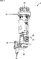
In
Bei den beiden Bewegungsachsen handelt es sich im Ausführungsbeispiel um rotatorische Achsen. Insbesondere ist dabei eine Schwenkachse
Das Greifarmelement ist weiterhin mit einer Ausgleichseinheit
Das Greifarmelement bildet erfindungsgemäß eine Greifarmverlängerung, wobei der Großteil des Roboterarms selbst überhaupt nicht mehr in den Behälter hineingeführt werden muss und somit auch keine Störkante mehr bildet, welche berücksichtigt werden müsste. Bevorzugt sind dabei die beiden Bewegungsachsen am unteren Ende des Greifarmelementes angeordnet. Bevorzugt muss dabei der Roboterarm oberhalb der Schwenkachse
Im Ausführungsbeispiel handelt es sich bei dem Greifer um einen mechanischen Greifer mit zwei Greiffingern
Weiterhin ist der Greifer gekröpft an dem Greifarmelement angeordnet. Insbesondere ist dabei der Greifer seitlich gegenüber der letzten Drehachse
Insbesondere kann so der Greifer bis an die Seitenwand des Behälters herangefahren werden, während das übrige Greifarmelement immer noch einen ausreichenden Abstand zur Seitenwand aufweist.In particular, so the gripper can be moved up to the side wall of the container, while the remaining Greifarmelement still has a sufficient distance from the side wall.
Wie anhand von
Der Behälter
Für die Manövrierbarkeit des Greifers ist dabei insbesondere die maximale Kröpfung K des Greifers in Bezug auf die Schwenkachse
Bevorzugt weist das Greifarmelement in Bezug auf den Behälter dabei die Abmessungen
Weiterhin bevorzugt weist das Greifarmelement in Bezug auf das Werkstück die Abmessungen
In
An diesem Flächenportal ist nun über eine rotatorische Achse
Alternativ könnte jedoch auf eine der drei rotatorischen Bewegungsachsen verzichtet werden, beispielsweise auf die rotatorische Achse
Alternativ zum Einsatzes eines Flächenportals mit 3 Linearachsen könnte auch ein Flächenportal mit nur 2 Linearachsen eingesetzt werden, wobei die fehlende Linearachse durch eine oder mehrere weitere Rotationsachsen, insbesondere zwei oder drei Rotationsachsen, ersetzt wird. Insbesondere könnte dabei die z-Achse des in
Die Ansteuerung des zweiten Ausführungsbeispiels kann dabei analog zur Ansteuerung des ersten Ausführungsbeispiels erfolgen. Insbesondere können auch hier die Achsen des Greifarmelementes und/oder die zusätzliche rotatorische Achse als reine Stellachsen betrieben werden, während das eigentliche Heranfahren an das Werkstück über das Flächenportal erfolgt.The control of the second embodiment can be carried out analogously to the control of the first embodiment. In particular, the axes of the Greifarmelementes and / or the additional rotary axis can be operated as a pure control axes here, while the actual approach to the workpiece via the surface portal.
Die vorliegende Erfindung ermöglicht so ein prozesssicheres Greifen von Werkstücken, welche so direkt aus einem Behälter entnommen und an einer Zielaufnahme abgelegt werden können.The present invention thus enables a process-reliable gripping of workpieces, which can thus be removed directly from a container and deposited on a target holder.
Weiterhin lässt sich durch die vorliegende Erfindung auch eine 100%-ige Entleerung des Behälters erreichen.Furthermore, can be achieved by the present invention, a 100% emptying of the container.
Claims (15)
Priority Applications (8)
| Application Number | Priority Date | Filing Date | Title |
|---|---|---|---|
| DE102013013114.6A DE102013013114A1 (en) | 2012-08-17 | 2013-08-06 | Device for the automated removal of workpieces arranged in a container |
| DK22167762.8T DK4046755T3 (en) | 2012-08-17 | 2013-08-16 | Device and method for automatically removing items placed in a container |
| EP13004082.7A EP2698234B1 (en) | 2012-08-17 | 2013-08-16 | Device and method for the automated removal of workpieces arranged in a container |
| DK13004082.7T DK2698234T3 (en) | 2012-08-17 | 2013-08-16 | Arrangement and method for automated removal of items placed in a container |
| US13/968,471 US9902066B2 (en) | 2012-08-17 | 2013-08-16 | Apparatus for automated removal of workpieces arranged in a container |
| EP22167762.8A EP4046755B1 (en) | 2012-08-17 | 2013-08-16 | Device and method for the automated removal of workpieces arranged in a container |
| KR1020130097407A KR102115983B1 (en) | 2012-08-17 | 2013-08-16 | Apparatus for automated removal of workpieces arranged in a container |
| CN201310362081.5A CN103586865B (en) | 2012-08-17 | 2013-08-19 | For automatically taking out the device of the workpiece of arrangement in a reservoir |
Applications Claiming Priority (3)
| Application Number | Priority Date | Filing Date | Title |
|---|---|---|---|
| DE102012016537.4 | 2012-08-17 | ||
| DE102012016537 | 2012-08-17 | ||
| DE102013013114.6A DE102013013114A1 (en) | 2012-08-17 | 2013-08-06 | Device for the automated removal of workpieces arranged in a container |
Publications (1)
| Publication Number | Publication Date |
|---|---|
| DE102013013114A1 true DE102013013114A1 (en) | 2014-02-20 |
Family
ID=49003626
Family Applications (1)
| Application Number | Title | Priority Date | Filing Date |
|---|---|---|---|
| DE102013013114.6A Ceased DE102013013114A1 (en) | 2012-08-17 | 2013-08-06 | Device for the automated removal of workpieces arranged in a container |
Country Status (6)
| Country | Link |
|---|---|
| US (1) | US9902066B2 (en) |
| EP (2) | EP2698234B1 (en) |
| KR (1) | KR102115983B1 (en) |
| CN (1) | CN103586865B (en) |
| DE (1) | DE102013013114A1 (en) |
| DK (2) | DK4046755T3 (en) |
Cited By (6)
| Publication number | Priority date | Publication date | Assignee | Title |
|---|---|---|---|---|
| DE102016204258A1 (en) | 2016-03-15 | 2017-09-21 | Volkswagen Aktiengesellschaft | Apparatus and method for automated gripping and handling of workpieces |
| EP3351351A1 (en) | 2017-01-20 | 2018-07-25 | Liebherr-Verzahntechnik GmbH | Device for the automated removal of workpieces arranged in a container |
| EP3351350A2 (en) | 2017-01-20 | 2018-07-25 | Liebherr-Verzahntechnik GmbH | Device for the automated removal of workpieces arranged in a container |
| DE102021125421A1 (en) | 2021-09-30 | 2023-03-30 | Audi Aktiengesellschaft | Gripping device and method for removing a component from a container |
| US20240109198A1 (en) * | 2022-10-04 | 2024-04-04 | J. Schmalz Gmbh | Method for handling objects, and handling system |
| DE102022212255A1 (en) | 2022-11-17 | 2024-05-23 | Volkswagen Aktiengesellschaft | Removal device for removing workpieces randomly held in a workpiece container |
Families Citing this family (24)
| Publication number | Priority date | Publication date | Assignee | Title |
|---|---|---|---|---|
| DE102014008444A1 (en) | 2014-06-06 | 2015-12-17 | Liebherr-Verzahntechnik Gmbh | Device for the automated removal of workpieces arranged in a container |
| CN106144574A (en) * | 2015-04-16 | 2016-11-23 | 株式会社安川电机 | A kind of handling system and transfer robot |
| US10023393B2 (en) * | 2015-09-29 | 2018-07-17 | Amazon Technologies, Inc. | Robotic tossing of items in inventory system |
| CN106429137A (en) * | 2016-06-28 | 2017-02-22 | 武汉贝索医疗器械有限公司 | Automatic storing and taking device for ultra-low temperature refrigeration house articles |
| WO2018146740A1 (en) * | 2017-02-08 | 2018-08-16 | 株式会社Fuji | Work machine |
| DE102017003199A1 (en) * | 2017-04-03 | 2018-10-04 | Robot-Technology Gmbh | Machining robot for machining workpieces with a laser beam |
| DE112017007394B4 (en) | 2017-04-04 | 2020-12-03 | Mujin, Inc. | Information processing device, gripping system, distribution system, program and information processing method |
| JP6444499B1 (en) * | 2017-04-04 | 2018-12-26 | 株式会社Mujin | Control device, picking system, distribution system, program, and control method |
| DE112017007397B4 (en) * | 2017-04-04 | 2021-09-30 | Mujin, Inc. | Control device, gripping system, distribution system, program, control method and manufacturing method |
| DE112017007392B4 (en) * | 2017-04-04 | 2021-11-04 | Mujin, Inc. | Control device, gripping system, distribution system, program, control method and manufacturing method |
| CN115385039A (en) * | 2017-04-04 | 2022-11-25 | 牧今科技 | Control device, information processing device, control method, and information processing method |
| JP6857145B2 (en) * | 2018-03-09 | 2021-04-14 | 株式会社日立製作所 | Orbit planning equipment, orbit planning method, and production system |
| JP7204513B2 (en) * | 2019-02-13 | 2023-01-16 | 株式会社東芝 | Controller and program |
| CN110125921A (en) * | 2019-05-13 | 2019-08-16 | 金陵科技学院 | A kind of pick device and its pick-up method for the pickup mobile phone from gap |
| IT201900013806A1 (en) * | 2019-08-02 | 2021-02-02 | TREBI Srl Unipersonale | SYSTEM FOR GRIPPING A PIECE, AS WELL AS GRIPPING HEAD THAT CAN BE USED IN THIS SYSTEM |
| US11331812B2 (en) | 2019-10-09 | 2022-05-17 | Michel St-Amand | Robotic manipulation of fabric pieces using a dropping-roller-type picker |
| CN110653805B (en) * | 2019-10-10 | 2022-11-04 | 西安科技大学 | Task-constrained path planning method for a seven-degree-of-freedom redundant manipulator in Cartesian space |
| CN111168346B (en) * | 2020-03-05 | 2021-03-12 | 青岛市市立医院 | A deep-hole grabbing robot for medical device assembly based on machine vision |
| EP3875227A1 (en) * | 2020-03-06 | 2021-09-08 | Scape Technologies A/S | Method of operating a picking robot and related devices |
| US11591194B2 (en) | 2020-07-14 | 2023-02-28 | Intrinsic Innovation Llc | Method and system for robotic pick-and-place comprising a container floor mounted to a transformable end of a lift mechanism and a set of container walls to define a container working volume with a working depth extends beyond a picking workspace of a robotic arm |
| CN112588597A (en) * | 2020-12-28 | 2021-04-02 | 上海擅韬信息技术有限公司 | Injection sorting device |
| EP4035850A1 (en) | 2021-02-02 | 2022-08-03 | Pick-It nv | End effector for picking up objects |
| FR3120069B1 (en) * | 2021-02-23 | 2023-02-10 | Michelin & Cie | Automated Cell for Crate Management Made during a Binding Process for Rubber Blocks |
| KR102900269B1 (en) * | 2023-01-19 | 2025-12-12 | 동국대학교 산학협력단 | Soft gripper device |
Family Cites Families (33)
| Publication number | Priority date | Publication date | Assignee | Title |
|---|---|---|---|---|
| US4937759A (en) * | 1986-02-18 | 1990-06-26 | Robotics Research Corporation | Industrial robot with controller |
| DE3620391A1 (en) | 1986-06-18 | 1987-12-23 | Wzl Lab Fuer Werkzeugmaschinen | Device for detachably connecting a tool, gripper, measuring instrument or other working system to the arm of a robot or the like |
| US5080415A (en) * | 1988-04-22 | 1992-01-14 | Beckman Instruments, Inc. | Robot gripper having auxiliary degree of freedom |
| FR2645788B1 (en) * | 1989-04-13 | 1995-07-28 | Sit Innovations Tech | TELEMANIPULATION MACHINE PROVIDED TO BE SUSPENDED FROM A LIFTING UNIT |
| JPH07112383A (en) * | 1993-08-23 | 1995-05-02 | Mazda Motor Corp | Article position recognition method, article transfer control method, and transfer control apparatus |
| JPH08191087A (en) * | 1995-01-10 | 1996-07-23 | Toshiba Seiki Kk | Wire bonding method and wire bonding apparatus |
| US5687831A (en) * | 1995-04-25 | 1997-11-18 | Adept Technology, Inc. | Flexible parts feeder |
| JP3476288B2 (en) * | 1995-08-31 | 2003-12-10 | ファナック株式会社 | Solid processing equipment using YAG cutting tool |
| WO2001051259A2 (en) * | 2000-01-11 | 2001-07-19 | Hai Hong Zhu | Modular robot manipulator apparatus |
| JP3805310B2 (en) * | 2003-01-30 | 2006-08-02 | ファナック株式会社 | Work take-out device |
| JP2005014108A (en) * | 2003-06-23 | 2005-01-20 | Honda Motor Co Ltd | Interference avoidance method for articulated robots |
| JP3876260B2 (en) * | 2004-09-16 | 2007-01-31 | ファナック株式会社 | Article supply equipment |
| DE102005058867B4 (en) * | 2005-12-09 | 2018-09-27 | Cine-Tv Broadcast Systems Gmbh | Method and device for moving a camera arranged on a pan and tilt head along a predetermined path of movement |
| AT8965U1 (en) | 2006-02-23 | 2007-03-15 | Engel Austria Gmbh | DEVICE FOR REMOVING AND / OR TRANSPORTING WORKPIECES |
| IS8494A (en) * | 2006-05-31 | 2008-12-02 | Valka Ehf | Grab arm for food |
| KR100857149B1 (en) * | 2006-07-04 | 2008-09-05 | 한국원자력연구원 | Telescopic Servo Manipulator |
| US7313464B1 (en) * | 2006-09-05 | 2007-12-25 | Adept Technology Inc. | Bin-picking system for randomly positioned objects |
| DE102007026956A1 (en) * | 2007-06-12 | 2008-12-18 | Kuka Innotec Gmbh | Method and system for robot-guided depalletizing of tires |
| US9144909B2 (en) * | 2007-07-05 | 2015-09-29 | Re2, Inc. | Defense related robotic systems |
| DE102007060653A1 (en) | 2007-12-15 | 2009-06-18 | Abb Ag | Position determination of an object |
| US8862269B2 (en) * | 2008-08-29 | 2014-10-14 | Abb Research Ltd. | Robotic picking of parts from a bin |
| US8606398B2 (en) * | 2008-08-29 | 2013-12-10 | Abb Research Ltd. | Compliant end of arm tooling for a robot |
| US9079308B2 (en) * | 2008-08-29 | 2015-07-14 | Abb Research Ltd. | Robotic picking of parts from a bin |
| JP5265296B2 (en) * | 2008-10-10 | 2013-08-14 | 本田技研工業株式会社 | Work removal method |
| IT1393421B1 (en) * | 2009-03-20 | 2012-04-20 | Berchi Group S P A | GRIPPING HEAD IN PARTICULAR FOR PACKAGING SYSTEM AND ITS PACKAGING SYSTEM |
| CN101559597B (en) * | 2009-05-12 | 2011-04-20 | 哈尔滨工程大学 | Multifunctional gantry type seven-shaft industrial robot |
| JP2012056017A (en) * | 2010-09-09 | 2012-03-22 | Honda Motor Co Ltd | Apparatus and method for transporting workpiece |
| JP5618198B2 (en) * | 2010-09-24 | 2014-11-05 | 株式会社安川電機 | Hand and robot |
| DE112011103794B4 (en) * | 2010-11-17 | 2019-01-24 | Mitsubishi Electric Corporation | Pick-up device for workpieces |
| JP5533727B2 (en) * | 2011-02-18 | 2014-06-25 | 株式会社安川電機 | Work picking system |
| JP5835926B2 (en) * | 2011-04-11 | 2015-12-24 | キヤノン株式会社 | Information processing apparatus, information processing apparatus control method, and program |
| JP5620445B2 (en) * | 2012-09-13 | 2014-11-05 | ファナック株式会社 | Article takeout device for determining holding position and posture of robot based on selection condition |
| US9662785B2 (en) * | 2015-03-19 | 2017-05-30 | Production Design Services, Inc. | Gantry robot system |
-
2013
- 2013-08-06 DE DE102013013114.6A patent/DE102013013114A1/en not_active Ceased
- 2013-08-16 DK DK22167762.8T patent/DK4046755T3/en active
- 2013-08-16 KR KR1020130097407A patent/KR102115983B1/en active Active
- 2013-08-16 EP EP13004082.7A patent/EP2698234B1/en active Active
- 2013-08-16 EP EP22167762.8A patent/EP4046755B1/en active Active
- 2013-08-16 DK DK13004082.7T patent/DK2698234T3/en active
- 2013-08-16 US US13/968,471 patent/US9902066B2/en active Active
- 2013-08-19 CN CN201310362081.5A patent/CN103586865B/en active Active
Cited By (11)
| Publication number | Priority date | Publication date | Assignee | Title |
|---|---|---|---|---|
| DE102016204258A1 (en) | 2016-03-15 | 2017-09-21 | Volkswagen Aktiengesellschaft | Apparatus and method for automated gripping and handling of workpieces |
| EP3351351A1 (en) | 2017-01-20 | 2018-07-25 | Liebherr-Verzahntechnik GmbH | Device for the automated removal of workpieces arranged in a container |
| EP3351350A2 (en) | 2017-01-20 | 2018-07-25 | Liebherr-Verzahntechnik GmbH | Device for the automated removal of workpieces arranged in a container |
| DE102017000527A1 (en) | 2017-01-20 | 2018-07-26 | Liebherr-Verzahntechnik Gmbh | Device for the automated removal of workpieces arranged in a container |
| DE102017000524A1 (en) | 2017-01-20 | 2018-07-26 | Liebherr-Verzahntechnik Gmbh | Device for the automated removal of workpieces arranged in a container |
| US10507989B2 (en) | 2017-01-20 | 2019-12-17 | Liebherr-Verzahntechnik Gmbh | Apparatus for the automated removal of workpieces arranged in a bin |
| US10919709B2 (en) | 2017-01-20 | 2021-02-16 | Liebherr-Verzahntechnik Gmbh | Apparatus for the automated removal of workpieces arranged in a bin |
| DE102021125421A1 (en) | 2021-09-30 | 2023-03-30 | Audi Aktiengesellschaft | Gripping device and method for removing a component from a container |
| DE102021125421B4 (en) | 2021-09-30 | 2025-09-11 | Audi Aktiengesellschaft | Gripping device and method for removing a component from a container |
| US20240109198A1 (en) * | 2022-10-04 | 2024-04-04 | J. Schmalz Gmbh | Method for handling objects, and handling system |
| DE102022212255A1 (en) | 2022-11-17 | 2024-05-23 | Volkswagen Aktiengesellschaft | Removal device for removing workpieces randomly held in a workpiece container |
Also Published As
| Publication number | Publication date |
|---|---|
| DK4046755T3 (en) | 2024-03-11 |
| DK2698234T3 (en) | 2023-03-27 |
| KR20140023240A (en) | 2014-02-26 |
| EP2698234A2 (en) | 2014-02-19 |
| CN103586865A (en) | 2014-02-19 |
| KR102115983B1 (en) | 2020-06-05 |
| US9902066B2 (en) | 2018-02-27 |
| US20140052297A1 (en) | 2014-02-20 |
| EP4046755B1 (en) | 2024-02-28 |
| EP2698234B1 (en) | 2023-02-15 |
| CN103586865B (en) | 2018-04-10 |
| EP2698234A3 (en) | 2018-08-08 |
| EP4046755A1 (en) | 2022-08-24 |
Similar Documents
| Publication | Publication Date | Title |
|---|---|---|
| EP4046755B1 (en) | Device and method for the automated removal of workpieces arranged in a container | |
| EP2229262B1 (en) | Determining the position of an object | |
| EP3341164B1 (en) | Robot gripper | |
| DE102016005637B4 (en) | System for picking up objects and method for picking up stacked objects | |
| EP2073084B1 (en) | Method and device for controlling a robot's manipulator | |
| EP2679350B1 (en) | Device for the automatic detection and removal of workpieces | |
| EP2272637B1 (en) | Method and device for operating a manipulator | |
| EP2679354A2 (en) | Device for the automated handling of workpieces | |
| EP2679353A1 (en) | Device for the automated handling of workpieces | |
| DE102008062622A1 (en) | Method for command input in controller of manipulator, particularly robot, involves detecting force, which acts on manipulator in specific direction, and comparing detected force with stored forces | |
| EP2679352A1 (en) | Device for the automated removal of workpieces arranged in a container | |
| EP2883665A2 (en) | Method and device for controlling a manipulator | |
| DE102014008444A1 (en) | Device for the automated removal of workpieces arranged in a container | |
| DE102020100803A1 (en) | Follow-up robot and robot work system | |
| DE102011005513A1 (en) | Robot and method for operating a robot | |
| DE102007037404B4 (en) | Method for the mechanical processing and / or transfer of components | |
| EP1529605A2 (en) | Method and system for control of robots | |
| EP3311963A1 (en) | Positionable robot cell, production device with a processing unit and with positionable robot cell and method for operating such a robot cell which can be positioned | |
| DE102007011188B4 (en) | Apparatus and method for handling forgings | |
| EP2082852B1 (en) | Method and device for monitoring a manipulator | |
| WO2015135917A2 (en) | Method for operating a robot, and an associated robot comprising a mechanical feeler device | |
| WO2019170527A1 (en) | Pivoting unit for a handling robot and associated method | |
| DE102014201616B4 (en) | Modular, universal stacking system for large pressed parts | |
| AT521085B1 (en) | Method for controlling the movement of a workpiece | |
| DE102024121685A1 (en) | System comprising a crane and a robot, and methods for operating such a system |
Legal Events
| Date | Code | Title | Description |
|---|---|---|---|
| R012 | Request for examination validly filed | ||
| R002 | Refusal decision in examination/registration proceedings | ||
| R003 | Refusal decision now final |