DE102013004964B4 - Instrument set and method for inserting a basket into the disc space between two vertebral bodies - Google Patents
Instrument set and method for inserting a basket into the disc space between two vertebral bodies Download PDFInfo
- Publication number
- DE102013004964B4 DE102013004964B4 DE102013004964.4A DE102013004964A DE102013004964B4 DE 102013004964 B4 DE102013004964 B4 DE 102013004964B4 DE 102013004964 A DE102013004964 A DE 102013004964A DE 102013004964 B4 DE102013004964 B4 DE 102013004964B4
- Authority
- DE
- Germany
- Prior art keywords
- basket
- set according
- working sleeve
- vertebral bodies
- distal
- Prior art date
- Legal status (The legal status is an assumption and is not a legal conclusion. Google has not performed a legal analysis and makes no representation as to the accuracy of the status listed.)
- Expired - Fee Related
Links
- 238000000034 method Methods 0.000 title description 15
- 238000003780 insertion Methods 0.000 claims description 33
- 230000037431 insertion Effects 0.000 claims description 33
- 239000000463 material Substances 0.000 description 8
- 210000000988 bone and bone Anatomy 0.000 description 3
- 230000004927 fusion Effects 0.000 description 3
- 238000003801 milling Methods 0.000 description 3
- 210000001087 myotubule Anatomy 0.000 description 3
- 210000004126 nerve fiber Anatomy 0.000 description 3
- 0 CC1=C*C2C1C2 Chemical compound CC1=C*C2C1C2 0.000 description 2
- 229910001069 Ti alloy Inorganic materials 0.000 description 2
- 230000006378 damage Effects 0.000 description 2
- 238000013461 design Methods 0.000 description 2
- 238000011161 development Methods 0.000 description 2
- 230000018109 developmental process Effects 0.000 description 2
- 238000010894 electron beam technology Methods 0.000 description 2
- 239000007943 implant Substances 0.000 description 2
- 238000002844 melting Methods 0.000 description 2
- 230000008018 melting Effects 0.000 description 2
- 210000003205 muscle Anatomy 0.000 description 2
- 230000006641 stabilisation Effects 0.000 description 2
- 238000011105 stabilization Methods 0.000 description 2
- 208000034656 Contusions Diseases 0.000 description 1
- 208000003618 Intervertebral Disc Displacement Diseases 0.000 description 1
- 206010055039 Intervertebral disc compression Diseases 0.000 description 1
- 208000031481 Pathologic Constriction Diseases 0.000 description 1
- 208000020339 Spinal injury Diseases 0.000 description 1
- 208000007103 Spondylolisthesis Diseases 0.000 description 1
- 206010052428 Wound Diseases 0.000 description 1
- 208000027418 Wounds and injury Diseases 0.000 description 1
- 230000002411 adverse Effects 0.000 description 1
- 239000000316 bone substitute Substances 0.000 description 1
- 210000004027 cell Anatomy 0.000 description 1
- 101150038956 cup-4 gene Proteins 0.000 description 1
- 229910003460 diamond Inorganic materials 0.000 description 1
- 239000010432 diamond Substances 0.000 description 1
- 230000000694 effects Effects 0.000 description 1
- 238000002695 general anesthesia Methods 0.000 description 1
- 230000003902 lesion Effects 0.000 description 1
- 229910052751 metal Inorganic materials 0.000 description 1
- 239000002184 metal Substances 0.000 description 1
- 210000005036 nerve Anatomy 0.000 description 1
- 230000000149 penetrating effect Effects 0.000 description 1
- 239000000843 powder Substances 0.000 description 1
- 238000012797 qualification Methods 0.000 description 1
- 238000002271 resection Methods 0.000 description 1
- 210000000278 spinal cord Anatomy 0.000 description 1
- 230000036262 stenosis Effects 0.000 description 1
- 208000037804 stenosis Diseases 0.000 description 1
- 238000001356 surgical procedure Methods 0.000 description 1
- 210000000115 thoracic cavity Anatomy 0.000 description 1
- 210000001519 tissue Anatomy 0.000 description 1
- 238000011179 visual inspection Methods 0.000 description 1
- 210000002517 zygapophyseal joint Anatomy 0.000 description 1
Images


Classifications
-
- A—HUMAN NECESSITIES
- A61—MEDICAL OR VETERINARY SCIENCE; HYGIENE
- A61F—FILTERS IMPLANTABLE INTO BLOOD VESSELS; PROSTHESES; DEVICES PROVIDING PATENCY TO, OR PREVENTING COLLAPSING OF, TUBULAR STRUCTURES OF THE BODY, e.g. STENTS; ORTHOPAEDIC, NURSING OR CONTRACEPTIVE DEVICES; FOMENTATION; TREATMENT OR PROTECTION OF EYES OR EARS; BANDAGES, DRESSINGS OR ABSORBENT PADS; FIRST-AID KITS
- A61F2/00—Filters implantable into blood vessels; Prostheses, i.e. artificial substitutes or replacements for parts of the body; Appliances for connecting them with the body; Devices providing patency to, or preventing collapsing of, tubular structures of the body, e.g. stents
- A61F2/02—Prostheses implantable into the body
- A61F2/30—Joints
- A61F2/46—Special tools for implanting artificial joints
- A61F2/4603—Special tools for implanting artificial joints for insertion or extraction of endoprosthetic joints or of accessories thereof
- A61F2/4611—Special tools for implanting artificial joints for insertion or extraction of endoprosthetic joints or of accessories thereof of spinal prostheses
-
- A—HUMAN NECESSITIES
- A61—MEDICAL OR VETERINARY SCIENCE; HYGIENE
- A61B—DIAGNOSIS; SURGERY; IDENTIFICATION
- A61B17/00—Surgical instruments, devices or methods
- A61B17/16—Instruments for performing osteoclasis; Drills or chisels for bones; Trepans
- A61B17/1604—Chisels; Rongeurs; Punches; Stamps
-
- A—HUMAN NECESSITIES
- A61—MEDICAL OR VETERINARY SCIENCE; HYGIENE
- A61B—DIAGNOSIS; SURGERY; IDENTIFICATION
- A61B17/00—Surgical instruments, devices or methods
- A61B17/16—Instruments for performing osteoclasis; Drills or chisels for bones; Trepans
- A61B17/1662—Instruments for performing osteoclasis; Drills or chisels for bones; Trepans for particular parts of the body
- A61B17/1671—Instruments for performing osteoclasis; Drills or chisels for bones; Trepans for particular parts of the body for the spine
-
- A—HUMAN NECESSITIES
- A61—MEDICAL OR VETERINARY SCIENCE; HYGIENE
- A61B—DIAGNOSIS; SURGERY; IDENTIFICATION
- A61B17/00—Surgical instruments, devices or methods
- A61B17/16—Instruments for performing osteoclasis; Drills or chisels for bones; Trepans
- A61B17/17—Guides or aligning means for drills, mills, pins or wires
- A61B17/1739—Guides or aligning means for drills, mills, pins or wires specially adapted for particular parts of the body
- A61B17/1757—Guides or aligning means for drills, mills, pins or wires specially adapted for particular parts of the body for the spine
-
- A—HUMAN NECESSITIES
- A61—MEDICAL OR VETERINARY SCIENCE; HYGIENE
- A61F—FILTERS IMPLANTABLE INTO BLOOD VESSELS; PROSTHESES; DEVICES PROVIDING PATENCY TO, OR PREVENTING COLLAPSING OF, TUBULAR STRUCTURES OF THE BODY, e.g. STENTS; ORTHOPAEDIC, NURSING OR CONTRACEPTIVE DEVICES; FOMENTATION; TREATMENT OR PROTECTION OF EYES OR EARS; BANDAGES, DRESSINGS OR ABSORBENT PADS; FIRST-AID KITS
- A61F2/00—Filters implantable into blood vessels; Prostheses, i.e. artificial substitutes or replacements for parts of the body; Appliances for connecting them with the body; Devices providing patency to, or preventing collapsing of, tubular structures of the body, e.g. stents
- A61F2/02—Prostheses implantable into the body
- A61F2/30—Joints
- A61F2/44—Joints for the spine, e.g. vertebrae, spinal discs
- A61F2/4455—Joints for the spine, e.g. vertebrae, spinal discs for the fusion of spinal bodies, e.g. intervertebral fusion of adjacent spinal bodies, e.g. fusion cages
- A61F2/447—Joints for the spine, e.g. vertebrae, spinal discs for the fusion of spinal bodies, e.g. intervertebral fusion of adjacent spinal bodies, e.g. fusion cages substantially parallelepipedal, e.g. having a rectangular or trapezoidal cross-section
-
- A—HUMAN NECESSITIES
- A61—MEDICAL OR VETERINARY SCIENCE; HYGIENE
- A61B—DIAGNOSIS; SURGERY; IDENTIFICATION
- A61B17/00—Surgical instruments, devices or methods
- A61B17/16—Instruments for performing osteoclasis; Drills or chisels for bones; Trepans
- A61B2017/1602—Mills
-
- A—HUMAN NECESSITIES
- A61—MEDICAL OR VETERINARY SCIENCE; HYGIENE
- A61F—FILTERS IMPLANTABLE INTO BLOOD VESSELS; PROSTHESES; DEVICES PROVIDING PATENCY TO, OR PREVENTING COLLAPSING OF, TUBULAR STRUCTURES OF THE BODY, e.g. STENTS; ORTHOPAEDIC, NURSING OR CONTRACEPTIVE DEVICES; FOMENTATION; TREATMENT OR PROTECTION OF EYES OR EARS; BANDAGES, DRESSINGS OR ABSORBENT PADS; FIRST-AID KITS
- A61F2/00—Filters implantable into blood vessels; Prostheses, i.e. artificial substitutes or replacements for parts of the body; Appliances for connecting them with the body; Devices providing patency to, or preventing collapsing of, tubular structures of the body, e.g. stents
- A61F2/02—Prostheses implantable into the body
- A61F2/30—Joints
- A61F2002/30001—Additional features of subject-matter classified in A61F2/28, A61F2/30 and subgroups thereof
- A61F2002/30003—Material related properties of the prosthesis or of a coating on the prosthesis
- A61F2002/30004—Material related properties of the prosthesis or of a coating on the prosthesis the prosthesis being made from materials having different values of a given property at different locations within the same prosthesis
- A61F2002/30011—Material related properties of the prosthesis or of a coating on the prosthesis the prosthesis being made from materials having different values of a given property at different locations within the same prosthesis differing in porosity
-
- A—HUMAN NECESSITIES
- A61—MEDICAL OR VETERINARY SCIENCE; HYGIENE
- A61F—FILTERS IMPLANTABLE INTO BLOOD VESSELS; PROSTHESES; DEVICES PROVIDING PATENCY TO, OR PREVENTING COLLAPSING OF, TUBULAR STRUCTURES OF THE BODY, e.g. STENTS; ORTHOPAEDIC, NURSING OR CONTRACEPTIVE DEVICES; FOMENTATION; TREATMENT OR PROTECTION OF EYES OR EARS; BANDAGES, DRESSINGS OR ABSORBENT PADS; FIRST-AID KITS
- A61F2/00—Filters implantable into blood vessels; Prostheses, i.e. artificial substitutes or replacements for parts of the body; Appliances for connecting them with the body; Devices providing patency to, or preventing collapsing of, tubular structures of the body, e.g. stents
- A61F2/02—Prostheses implantable into the body
- A61F2/30—Joints
- A61F2002/30001—Additional features of subject-matter classified in A61F2/28, A61F2/30 and subgroups thereof
- A61F2002/30108—Shapes
- A61F2002/3011—Cross-sections or two-dimensional shapes
- A61F2002/30159—Concave polygonal shapes
- A61F2002/30172—T-shaped
-
- A—HUMAN NECESSITIES
- A61—MEDICAL OR VETERINARY SCIENCE; HYGIENE
- A61F—FILTERS IMPLANTABLE INTO BLOOD VESSELS; PROSTHESES; DEVICES PROVIDING PATENCY TO, OR PREVENTING COLLAPSING OF, TUBULAR STRUCTURES OF THE BODY, e.g. STENTS; ORTHOPAEDIC, NURSING OR CONTRACEPTIVE DEVICES; FOMENTATION; TREATMENT OR PROTECTION OF EYES OR EARS; BANDAGES, DRESSINGS OR ABSORBENT PADS; FIRST-AID KITS
- A61F2/00—Filters implantable into blood vessels; Prostheses, i.e. artificial substitutes or replacements for parts of the body; Appliances for connecting them with the body; Devices providing patency to, or preventing collapsing of, tubular structures of the body, e.g. stents
- A61F2/02—Prostheses implantable into the body
- A61F2/30—Joints
- A61F2002/30001—Additional features of subject-matter classified in A61F2/28, A61F2/30 and subgroups thereof
- A61F2002/30108—Shapes
- A61F2002/30199—Three-dimensional shapes
- A61F2002/30289—Three-dimensional shapes helically-coiled
-
- A—HUMAN NECESSITIES
- A61—MEDICAL OR VETERINARY SCIENCE; HYGIENE
- A61F—FILTERS IMPLANTABLE INTO BLOOD VESSELS; PROSTHESES; DEVICES PROVIDING PATENCY TO, OR PREVENTING COLLAPSING OF, TUBULAR STRUCTURES OF THE BODY, e.g. STENTS; ORTHOPAEDIC, NURSING OR CONTRACEPTIVE DEVICES; FOMENTATION; TREATMENT OR PROTECTION OF EYES OR EARS; BANDAGES, DRESSINGS OR ABSORBENT PADS; FIRST-AID KITS
- A61F2/00—Filters implantable into blood vessels; Prostheses, i.e. artificial substitutes or replacements for parts of the body; Appliances for connecting them with the body; Devices providing patency to, or preventing collapsing of, tubular structures of the body, e.g. stents
- A61F2/02—Prostheses implantable into the body
- A61F2/30—Joints
- A61F2002/30001—Additional features of subject-matter classified in A61F2/28, A61F2/30 and subgroups thereof
- A61F2002/30316—The prosthesis having different structural features at different locations within the same prosthesis; Connections between prosthetic parts; Special structural features of bone or joint prostheses not otherwise provided for
- A61F2002/30329—Connections or couplings between prosthetic parts, e.g. between modular parts; Connecting elements
- A61F2002/30428—Connections or couplings between prosthetic parts, e.g. between modular parts; Connecting elements made by inserting a protrusion into a slot
-
- A—HUMAN NECESSITIES
- A61—MEDICAL OR VETERINARY SCIENCE; HYGIENE
- A61F—FILTERS IMPLANTABLE INTO BLOOD VESSELS; PROSTHESES; DEVICES PROVIDING PATENCY TO, OR PREVENTING COLLAPSING OF, TUBULAR STRUCTURES OF THE BODY, e.g. STENTS; ORTHOPAEDIC, NURSING OR CONTRACEPTIVE DEVICES; FOMENTATION; TREATMENT OR PROTECTION OF EYES OR EARS; BANDAGES, DRESSINGS OR ABSORBENT PADS; FIRST-AID KITS
- A61F2/00—Filters implantable into blood vessels; Prostheses, i.e. artificial substitutes or replacements for parts of the body; Appliances for connecting them with the body; Devices providing patency to, or preventing collapsing of, tubular structures of the body, e.g. stents
- A61F2/02—Prostheses implantable into the body
- A61F2/30—Joints
- A61F2002/30001—Additional features of subject-matter classified in A61F2/28, A61F2/30 and subgroups thereof
- A61F2002/30316—The prosthesis having different structural features at different locations within the same prosthesis; Connections between prosthetic parts; Special structural features of bone or joint prostheses not otherwise provided for
- A61F2002/30535—Special structural features of bone or joint prostheses not otherwise provided for
- A61F2002/30537—Special structural features of bone or joint prostheses not otherwise provided for adjustable
- A61F2002/30538—Special structural features of bone or joint prostheses not otherwise provided for adjustable for adjusting angular orientation
-
- A—HUMAN NECESSITIES
- A61—MEDICAL OR VETERINARY SCIENCE; HYGIENE
- A61F—FILTERS IMPLANTABLE INTO BLOOD VESSELS; PROSTHESES; DEVICES PROVIDING PATENCY TO, OR PREVENTING COLLAPSING OF, TUBULAR STRUCTURES OF THE BODY, e.g. STENTS; ORTHOPAEDIC, NURSING OR CONTRACEPTIVE DEVICES; FOMENTATION; TREATMENT OR PROTECTION OF EYES OR EARS; BANDAGES, DRESSINGS OR ABSORBENT PADS; FIRST-AID KITS
- A61F2/00—Filters implantable into blood vessels; Prostheses, i.e. artificial substitutes or replacements for parts of the body; Appliances for connecting them with the body; Devices providing patency to, or preventing collapsing of, tubular structures of the body, e.g. stents
- A61F2/02—Prostheses implantable into the body
- A61F2/30—Joints
- A61F2002/30001—Additional features of subject-matter classified in A61F2/28, A61F2/30 and subgroups thereof
- A61F2002/30316—The prosthesis having different structural features at different locations within the same prosthesis; Connections between prosthetic parts; Special structural features of bone or joint prostheses not otherwise provided for
- A61F2002/30535—Special structural features of bone or joint prostheses not otherwise provided for
- A61F2002/30593—Special structural features of bone or joint prostheses not otherwise provided for hollow
-
- A—HUMAN NECESSITIES
- A61—MEDICAL OR VETERINARY SCIENCE; HYGIENE
- A61F—FILTERS IMPLANTABLE INTO BLOOD VESSELS; PROSTHESES; DEVICES PROVIDING PATENCY TO, OR PREVENTING COLLAPSING OF, TUBULAR STRUCTURES OF THE BODY, e.g. STENTS; ORTHOPAEDIC, NURSING OR CONTRACEPTIVE DEVICES; FOMENTATION; TREATMENT OR PROTECTION OF EYES OR EARS; BANDAGES, DRESSINGS OR ABSORBENT PADS; FIRST-AID KITS
- A61F2/00—Filters implantable into blood vessels; Prostheses, i.e. artificial substitutes or replacements for parts of the body; Appliances for connecting them with the body; Devices providing patency to, or preventing collapsing of, tubular structures of the body, e.g. stents
- A61F2/02—Prostheses implantable into the body
- A61F2/30—Joints
- A61F2002/30001—Additional features of subject-matter classified in A61F2/28, A61F2/30 and subgroups thereof
- A61F2002/30316—The prosthesis having different structural features at different locations within the same prosthesis; Connections between prosthetic parts; Special structural features of bone or joint prostheses not otherwise provided for
- A61F2002/30535—Special structural features of bone or joint prostheses not otherwise provided for
- A61F2002/30604—Special structural features of bone or joint prostheses not otherwise provided for modular
- A61F2002/30616—Sets comprising a plurality of prosthetic parts of different sizes or orientations
-
- A—HUMAN NECESSITIES
- A61—MEDICAL OR VETERINARY SCIENCE; HYGIENE
- A61F—FILTERS IMPLANTABLE INTO BLOOD VESSELS; PROSTHESES; DEVICES PROVIDING PATENCY TO, OR PREVENTING COLLAPSING OF, TUBULAR STRUCTURES OF THE BODY, e.g. STENTS; ORTHOPAEDIC, NURSING OR CONTRACEPTIVE DEVICES; FOMENTATION; TREATMENT OR PROTECTION OF EYES OR EARS; BANDAGES, DRESSINGS OR ABSORBENT PADS; FIRST-AID KITS
- A61F2/00—Filters implantable into blood vessels; Prostheses, i.e. artificial substitutes or replacements for parts of the body; Appliances for connecting them with the body; Devices providing patency to, or preventing collapsing of, tubular structures of the body, e.g. stents
- A61F2/02—Prostheses implantable into the body
- A61F2/30—Joints
- A61F2/30767—Special external or bone-contacting surface, e.g. coating for improving bone ingrowth
- A61F2/30771—Special external or bone-contacting surface, e.g. coating for improving bone ingrowth applied in original prostheses, e.g. holes or grooves
- A61F2002/30795—Blind bores, e.g. of circular cross-section
-
- A—HUMAN NECESSITIES
- A61—MEDICAL OR VETERINARY SCIENCE; HYGIENE
- A61F—FILTERS IMPLANTABLE INTO BLOOD VESSELS; PROSTHESES; DEVICES PROVIDING PATENCY TO, OR PREVENTING COLLAPSING OF, TUBULAR STRUCTURES OF THE BODY, e.g. STENTS; ORTHOPAEDIC, NURSING OR CONTRACEPTIVE DEVICES; FOMENTATION; TREATMENT OR PROTECTION OF EYES OR EARS; BANDAGES, DRESSINGS OR ABSORBENT PADS; FIRST-AID KITS
- A61F2/00—Filters implantable into blood vessels; Prostheses, i.e. artificial substitutes or replacements for parts of the body; Appliances for connecting them with the body; Devices providing patency to, or preventing collapsing of, tubular structures of the body, e.g. stents
- A61F2/02—Prostheses implantable into the body
- A61F2/30—Joints
- A61F2/30767—Special external or bone-contacting surface, e.g. coating for improving bone ingrowth
- A61F2/30907—Nets or sleeves applied to surface of prostheses or in cement
- A61F2002/30909—Nets
-
- A—HUMAN NECESSITIES
- A61—MEDICAL OR VETERINARY SCIENCE; HYGIENE
- A61F—FILTERS IMPLANTABLE INTO BLOOD VESSELS; PROSTHESES; DEVICES PROVIDING PATENCY TO, OR PREVENTING COLLAPSING OF, TUBULAR STRUCTURES OF THE BODY, e.g. STENTS; ORTHOPAEDIC, NURSING OR CONTRACEPTIVE DEVICES; FOMENTATION; TREATMENT OR PROTECTION OF EYES OR EARS; BANDAGES, DRESSINGS OR ABSORBENT PADS; FIRST-AID KITS
- A61F2/00—Filters implantable into blood vessels; Prostheses, i.e. artificial substitutes or replacements for parts of the body; Appliances for connecting them with the body; Devices providing patency to, or preventing collapsing of, tubular structures of the body, e.g. stents
- A61F2/02—Prostheses implantable into the body
- A61F2/30—Joints
- A61F2/44—Joints for the spine, e.g. vertebrae, spinal discs
- A61F2002/4495—Joints for the spine, e.g. vertebrae, spinal discs having a fabric structure, e.g. made from wires or fibres
-
- A—HUMAN NECESSITIES
- A61—MEDICAL OR VETERINARY SCIENCE; HYGIENE
- A61F—FILTERS IMPLANTABLE INTO BLOOD VESSELS; PROSTHESES; DEVICES PROVIDING PATENCY TO, OR PREVENTING COLLAPSING OF, TUBULAR STRUCTURES OF THE BODY, e.g. STENTS; ORTHOPAEDIC, NURSING OR CONTRACEPTIVE DEVICES; FOMENTATION; TREATMENT OR PROTECTION OF EYES OR EARS; BANDAGES, DRESSINGS OR ABSORBENT PADS; FIRST-AID KITS
- A61F2/00—Filters implantable into blood vessels; Prostheses, i.e. artificial substitutes or replacements for parts of the body; Appliances for connecting them with the body; Devices providing patency to, or preventing collapsing of, tubular structures of the body, e.g. stents
- A61F2/02—Prostheses implantable into the body
- A61F2/30—Joints
- A61F2/46—Special tools for implanting artificial joints
- A61F2/4603—Special tools for implanting artificial joints for insertion or extraction of endoprosthetic joints or of accessories thereof
- A61F2002/4625—Special tools for implanting artificial joints for insertion or extraction of endoprosthetic joints or of accessories thereof with relative movement between parts of the instrument during use
- A61F2002/4627—Special tools for implanting artificial joints for insertion or extraction of endoprosthetic joints or of accessories thereof with relative movement between parts of the instrument during use with linear motion along or rotating motion about the instrument axis or the implantation direction, e.g. telescopic, along a guiding rod, screwing inside the instrument
-
- A—HUMAN NECESSITIES
- A61—MEDICAL OR VETERINARY SCIENCE; HYGIENE
- A61F—FILTERS IMPLANTABLE INTO BLOOD VESSELS; PROSTHESES; DEVICES PROVIDING PATENCY TO, OR PREVENTING COLLAPSING OF, TUBULAR STRUCTURES OF THE BODY, e.g. STENTS; ORTHOPAEDIC, NURSING OR CONTRACEPTIVE DEVICES; FOMENTATION; TREATMENT OR PROTECTION OF EYES OR EARS; BANDAGES, DRESSINGS OR ABSORBENT PADS; FIRST-AID KITS
- A61F2310/00—Prostheses classified in A61F2/28 or A61F2/30 - A61F2/44 being constructed from or coated with a particular material
- A61F2310/00005—The prosthesis being constructed from a particular material
- A61F2310/00011—Metals or alloys
- A61F2310/00023—Titanium or titanium-based alloys, e.g. Ti-Ni alloys
Landscapes
- Health & Medical Sciences (AREA)
- Biomedical Technology (AREA)
- Engineering & Computer Science (AREA)
- Orthopedic Medicine & Surgery (AREA)
- Life Sciences & Earth Sciences (AREA)
- Surgery (AREA)
- Veterinary Medicine (AREA)
- Public Health (AREA)
- Oral & Maxillofacial Surgery (AREA)
- Heart & Thoracic Surgery (AREA)
- Animal Behavior & Ethology (AREA)
- General Health & Medical Sciences (AREA)
- Transplantation (AREA)
- Neurology (AREA)
- Dentistry (AREA)
- Nuclear Medicine, Radiotherapy & Molecular Imaging (AREA)
- Molecular Biology (AREA)
- Medical Informatics (AREA)
- Cardiology (AREA)
- Vascular Medicine (AREA)
- Physical Education & Sports Medicine (AREA)
- Prostheses (AREA)
- Surgical Instruments (AREA)
Abstract
Instrumentenset zum Einbringen eines Körbchens in das Bandscheibenfach zwischen zwei Wirbelkörpern, mit einem Führungsdraht (2.1), mit mehreren über den Führungsdraht und übereinander aufschiebbaren Dilatoren (2.3–2.6) mit einer Arbeitshülse (3) und mit einem Körbchen (4), dadurch gekennzeichnet, dass die Arbeitshülse (3) in ihrem distalen Mantelbereich mit Schlitzen (3.4) und dazwischen angeordneten Rippen (3.5) versehen ist und in ihrem distalen Bereich derart flexibel ausgebildet ist, dass die Arbeitshülse (3) ein Festlegen ihres distalen Bereichs an den Wirbelkörpern (1.1, 1.2) in Richtung ihrer Erstreckung bei gleichzeitiger angularer Beweglichkeit oder variabler angularer Ausrichtbarkeit ihrer proximalen Stirnseite (3.6) ermöglicht.Instrument set for inserting a basket into the intervertebral disc space between two vertebral bodies, comprising a guide wire (2.1), a plurality of dilators (2.3-2.6) slidable over the guide wire and superimposed with a working sleeve (3) and a basket (4), characterized in that the working sleeve (3) is provided in its distal jacket area with slots (3.4) and ribs (3.5) arranged therebetween and is flexible enough in its distal area such that the working sleeve (3) fixes its distal area to the vertebral bodies (1.1 , 1.2) in the direction of its extension with simultaneous angular mobility or variable angular alignability of its proximal end face (3.6).
Description
Die Erfindung betrifft ein Instrumentenset zum Einbringen eines Körbchens in das Bandscheibenfach zwischen zwei Wirbelkörpern nach dem Oberbegriff des Anspruchs 1.The invention relates to a set of instruments for introducing a basket into the intervertebral disc space between two vertebral bodies according to the preamble of
Bei einer Reihe von Wirbelsäulenschäden, insbesondere Bandscheibenschäden, wie Wirbelgleiten und Instabilität nach einem Bandscheibenvorfall und Stenose, wird eine Versteifung der Wirbelsäule zwischen den beiden von dem Schaden betroffenen Wirbelkörpern durchgeführt. Hierzu wird ein Körbchen (Cage) zwischen die Wirbelkörper in das ausgeräumte Bandscheibenfach eingebracht, mit dem die Wirbelkörper verwachsen. Dies wird als lumbale Wirbelfusion (Lumbar Interbody Fusion – LIF) bezeichnet. Für die Brust- und Halswirbelsäule gibt es ähnliche Verfahren. Hierzu wird in der Regel ein Hautschnitt durchgeführt, um unter Sicht zum Bandscheibenfach vordringen zu können, wobei dies mit Muskel-Destruktion verbunden ist. Dabei kann zusätzlich eine perkutane Verschraubung in minimal-invasiver Spinalchirurgie zur Gesamtstabilisierung erfolgen: Eine Reihe von Schrauben wird an die betroffenen Wirbelkörper befestigt.In a series of spinal injuries, particularly disc damage such as spondylolisthesis and instability following disc herniation and stenosis, spinal cord stiffening is performed between the two vertebral bodies affected by the lesion. For this purpose, a cage (Cage) is introduced between the vertebral bodies in the cleared intervertebral disc space, with which the vertebral bodies fused. This is called lumbar interbody fusion (LIF). There are similar procedures for the thoracic and cervical spine. For this purpose, a skin incision is usually performed in order to be able to penetrate under view of the disc space, which is associated with muscle destruction. In addition, a percutaneous screwing in minimally invasive spinal surgery for overall stabilization can be done: A set of screws is attached to the affected vertebrae.
Anschließend erfolgt eine Ausrichtung und Feinjustage der Schrauben und der Wirbelkörper zueinander, wonach die Schrauben über Querstangen miteinander verbunden werden und somit zueinander fixiert sind.Subsequently, an alignment and fine adjustment of the screws and the vertebrae to each other, after which the screws are connected to each other via cross bars and thus fixed to each other.
Die bekannten Zugangstechniken zum Einbringen von Körbchen in das Bandscheibenfach zwischen Wirbelkörpern sind mit Nachteilen und Gefahren behaftet.The known access techniques for inserting cups into the intervertebral disc space between vertebral bodies are associated with disadvantages and dangers.
In der
Die
Die
Der Erfindung liegt die Aufgabe zugrunde, ein Instrumentenset zum Einbringen eines Körbchens in das Bandscheibenfach bereitzustellen, mit welchem in einfacher Weise, unkompliziert und mit möglichst geringer Gefahr von Beeinträchtigungen des Patienten das Körbchen in das Bandscheibenfach eingebracht werden kann.The invention has for its object to provide a set of instruments for introducing a basket into the disc space, with which in a simple manner, uncomplicated and with the least possible risk of adverse effects on the patient, the basket can be inserted into the disc space.
Erfindungsgemäß wird die genannte Aufgabe mit einem Instrumentenset der eingangs genannten Art gelöst, welches die kennzeichnenden Merkmale des Anspruchs 1 aufweist.According to the invention, the object is achieved with an instrument set of the type mentioned, which has the characterizing features of
Die Erfindung sieht damit vor, dass die Arbeitshülse des Instrumentensets, die nach Aufweitung des Zugangswegs zum Arbeitsort, dem Bandscheibenfach, liegt, einerseits dort verankerbar ist, an den beiden das Bandscheibenfach oberhalb und unterhalb begrenzenden Wirbeln ein Widerlager findet und damit in der Achse ihrer Erstreckungsrichtung festgelegt ist, andererseits ihre Ausrichtung – insbesondere ihres proximalen Endes – relativ zum Bandscheibenfach bzw. zu dem dieses begrenzenden Wirbeln, oder der Wirbelsäule, insbesondere zu deren Erstreckungsrichtung, variabel ausrichtbar und so in gewissem Umfang beweglich ist.The invention thus provides that the working sleeve of the instrument set, which after widening the access path to the work place, the intervertebral disc space, is anchored there on the one hand finds an abutment on the two vertebrae above and below the intervertebral disc and thus in the axis of their extension direction is fixed, on the other hand, their orientation - in particular its proximal end - relative to the intervertebral disc or to this limiting vertebrae, or the spine, in particular to the direction of extension, is variably aligned and thus movable to some extent.
Bevorzugte Ausgestaltungen des Instrumentensets sehen weiterhin vor, dass das Körbchen und ein Einsetzinstrument zum Einbringen des Körbchens jeweils miteinander zusammenwirkende Verriegelungselemente aufweisen, die eine gemeinsame Verriegelung bilden, wobei insbesondere die Verriegelung von Einsetzinstrument und Körbchen eine angulare Beweglichkeit beider Teile erlaubt.Preferred embodiments of the instrument set further provide that the cup and an insertion instrument for inserting the cup each having mutually cooperating locking elements having a common Lock form, in particular, the locking of Einsetzinstrument and cups allow angular mobility of both parts.
In Weiterbildung kann vorgesehen sein, dass helikal oder auf einer Schraubenlinie mindestens zwei Schlitze durch einen Steg getrennt aufeinander fluchtend angeordnet sind, wobei weiterhin die Breiten von Schlitzen, Rippen und Stegen zwischen 0,5 mm und 2 mm liegen.In a further development, it can be provided that at least two slots are arranged helically or on a helix, separated by a web, so that the widths of slots, ribs and webs are between 0.5 mm and 2 mm.
In weiterer Ausgestaltung ist vorgesehen, dass das Körbchen an einer Stirnseite als Verriegelungselement eine Öffnung mit größerer Höhe als Breite aufweist, wobei die Öffnung in Richtung ihrer Breite mit einer Hinterschneidung versehen ist, wobei das Einsetzelement einen Stab mit einer am distalen Ende als Verriegelungselement ausgebildeten, sich radial erstreckenden Platte mit größerer Breite als Höhe aufweist, die mittels eines Griffs um die Achse des Stabs verschwenkbar ist.In a further embodiment it is provided that the cup has an opening with a greater height than width at one end face as a locking element, wherein the opening is provided with an undercut in the direction of its width, wherein the insertion element is a rod with a distal end formed as a locking element, having a radially extending plate of greater width than height, which is pivotable by means of a handle about the axis of the rod.
Grundsätzlich kann die Flexibilität oder Biegsamkeit der Arbeitshülse im distalen Bereich auch in anderer Weise erzielt werden, beispielsweise durch eine in Axialrichtung gegebene Abfolge von jeweils zwei oder drei Umfangsschlitzen mit verbleibenden Rippen und Stegen. Die helikal oder schraubenförmige Ausgestaltung hat den Vorteil, dass die Arbeitshülse so leichter durch Schraubbewegung eingeführt werden kann, wozu proximal vorzugsweise ein Radialhebel vorgesehen ist.In principle, the flexibility or flexibility of the working sleeve in the distal region can also be achieved in a different manner, for example by an axial sequence of two or three circumferential slots with remaining ribs and webs. The helical or helical configuration has the advantage that the working sleeve can be introduced so easily by screwing, for which purpose preferably a radial lever is provided proximally.
Weiterbildungen des Instrumentensets sehen vor, dass das Einsetzinstrument ein Rohr mit einer proximalen Griffhülse aufweist, durch das sich der Stab des Einsetzelements erstreckt, so dass die Platte relativ zum Rohr verschwenkbar ist und dass ein Widerlager am Rohr mit zwei parallel zueinander verlaufenden konvexen Stirnkanten ausgebildet ist.Further developments of the instrument set provide that the insertion instrument has a tube with a proximal grip sleeve through which the rod of the insertion extends, so that the plate is pivotable relative to the tube and that an abutment is formed on the tube with two mutually parallel convex end edges ,
Das Körbchen ist vorzugsweise mit netz- oder gitterförmigen Bereichen, insbesondere mit der Struktur einer Diamantgitterzelle, ausgebildet. Gitterförmige Bereiche an der Außenseite des Körbchens haben Öffnungsdurchmesser an jeder Öffnung in der Größenordnung von 500 μm bis 700 μm und/oder gitterförmige Bereiche im Inneren des Körbchens haben Öffnungen oder Durchbrüche mit Durchmessern von 1500 μm bis 3200 μm oder einen einheitlichen Öffnungsdurchmesser von 500 μm bis 3200 μm. Die Wandstärke des Materials liegt dabei vorzugsweise in der Größenordnung von 600 μm, insbesondere bei 800 μm.The basket is preferably formed with mesh or grid-shaped areas, in particular with the structure of a diamond grid cell. Latticed areas on the outside of the basket have aperture diameters at each aperture in the order of 500 microns to 700 microns and / or latticed areas inside the basket have openings or apertures with diameters of 1500 microns to 3200 microns or a uniform aperture diameter of 500 microns to 3200 μm. The wall thickness of the material is preferably in the order of 600 .mu.m, in particular at 800 microns.
Mit dem erfindungsgemäßen Instrumentenset wird wie folgt gearbeitet: Eine in ihrem distalen Mantelbereich flexibel ausgebildete Arbeitshülse wird eingeschoben; nach Entfernen der Bandscheibe aus dem Bandscheibenfach durch die Arbeitshülse wird ein Körbchen mit zumindest teilweise poröser Struktur mittels eines Einsetzinstruments, mit dem das Körbchen verriegelt ist, in das Bandscheibenfach eingeschoben; anschließend wird die Verriegelung zwischen Körbchen und Einsetzinstrument gelöst und danach die Arbeitshülse entfernt. Abgesehen von der Vermeidung der weiteren Nachteile des Standes der Technik ist bei dem Gegenstand der Erfindung insbesondere keine Facettengelenk-Resektion notwendig.The instrument set according to the invention operates as follows: a working sleeve which is flexibly formed in its distal jacket region is inserted; after removal of the intervertebral disc from the intervertebral disc space by the working sleeve, a basket with at least partially porous structure is inserted into the intervertebral disc space by means of an insertion instrument, with which the basket is locked; then the lock between the basket and insertion instrument is released and then removed the working sleeve. Apart from avoiding the further disadvantages of the prior art, in particular no facet joint resection is necessary in the subject matter of the invention.
Dabei werden die Instrumente transkutan vom Rücken her unter einem Winkel von mehr als 45° und weniger als 70°, vorzugsweise mehr als 55° und weniger als 65° zum Dornfortsatz bis zum Wirbelkörper eingeführt, wobei darüber hinaus die Instrumente vom Rücken her an der der Rückenoberflächen abgewandten Seite eines Querfortsatzes an den Wirbelkörpern eingeführt werden.The instruments are introduced transcutaneously from the back at an angle of more than 45 ° and less than 70 °, preferably more than 55 ° and less than 65 ° to the spinous process to the vertebral body, moreover, the instruments from the back to the Back surfaces facing away from a transverse process are introduced to the vertebral bodies.
Die in ihrem distalen Mantelbereich mit Schlitzen und zwischen diesen angeordneten Stegen versehene Arbeitshülse wird vorab über Dilatoren eingeführt, wobei insbesondere eine mit helikal verlaufenden Schlitzen in eine Schraubbewegung über die Dilatoren eingeführt wird. Ein porös ausgebildetes Körbchen wird durch die Arbeitshülse in das Bandscheibenfach eingeführt, wobei insbesondere ein Körbchen mit einer im Inneren gröberen und am Außenbereich feineren Porosität eingeführt wird.The working sleeve provided in its distal jacket region with slots and webs arranged between them is introduced in advance via dilators, wherein in particular a helically extending slot is introduced into a screw movement via the dilators. A porous cup is inserted through the working sleeve in the disc space, in particular a basket is introduced with a coarser inside and finer porosity on the outside.
Weitere Vorteile und Merkmale der Erfindung ergeben sich aus den Ansprüchen und aus der nachfolgenden Beschreibung, in der Ausführungsbeispiele der Erfindung unter Bezugnahme auf die Zeichnung im Einzelnen erläutert sind. Dabei zeigt: Further advantages and features of the invention will become apparent from the claims and from the following description, are explained in the embodiments of the invention with reference to the drawings in detail. Showing:
Die Erfindung befasst sich mit dem Einbringen eines Körbchens in den üblicherweise von Bandscheibengewebe ausgefüllten Zwischenraum zwischen zwei Wirbelkörpern eines Wirbelsegments, das Bandscheibenfach, zum Ersatz der Bandscheibe und dauerhafter Stabilisierung des Wirbelsegments, üblicherweise als (Lenden-)Wirbelfusion bezeichnet.The invention relates to the introduction of a basket in the space usually filled by intervertebral disc space between two vertebral bodies of a vertebral segment, the intervertebral disc space, to replace the disc and permanent stabilization of the vertebral segment, commonly referred to as (lumbar) vertebral fusion.
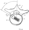
Zwischen den beiden Wirbelkörpern
Die Erfindung sieht, wie noch im Folgenden dargestellt wird, den Zugang zum Bandscheibenfach
Das erfindungsgemäße Instrumentarium oder Instrumentenset
Es kann ein doppelkanulierter Führungsstab
Weiterhin sind ein erster Dilator
Die Dilatoren
Weiter gehört zum Instrumentenset
Gegebenenfalls können auch drei oder vier Dilatoren ausreichen, über die dann eine Arbeitshülse geringeren Durchmessers geschoben wird.If necessary, three or four dilators can be sufficient, over which a working sleeve of smaller diameter is then pushed.
Bei den Arbeitshülsen
Weiterhin gehört zum erfindungsgemäßen Instrumentenset mindestens ein Körbchen
Das Körbchen
Ein Körbchen
Die Körbchen
Mit diesen Breiten und Höhen sind die Körbchen mit der größten Höhe durch die Arbeitshülse
Ein O-Cage (
Das Einsetzinstrument
Am distalen Ende des Stabs
Ein Körbchen
Zum Verbinden des Einsetzinstruments
Hierdurch kann die Platte
Ein Körbchen
Der Patient befindet sich vorzugsweise in stabiler Seitenlage (auch Bauchlage ist möglich) und ist durch eine Analgosedierung während der Operation ständig ansprechbar (er benötigt also keine Vollnarkose, wobei diese auch möglich ist). Der Operateur nimmt einen Einschnitt in der Haut des Rückens seitlich der Wirbelsäule (ca. 8–18 cm neben dem Dornfortsatz) vor, durch den dann unter einem Winkel zwischen 55° und 65°, vorzugsweise von ca. 60°, zuerst eine Hohlnadel
The patient is preferably in a stable lateral position (prone position is also possible) and is constantly approachable through an analgosedation during the operation (thus he does not need general anesthesia, although this is also possible). The surgeon makes an incision in the skin of the back of the spine (about 8-18 cm next to the spinous process), then at an angle between 55 ° and 65 °, preferably of about 60 °, first a hollow needle
Durch diese Nadel
Anschließend wird über den letzten Dilator (entweder
Durch die Arbeitshülse kann nun ein Endoskop
Anschließend wird der Fräser
Die Wirbelkörper
Nach Entfernen des Bandscheibenmaterials aus dem Bandscheibenfach
Nach Einbringen des Körbchens
Claims (13)
Priority Applications (9)
| Application Number | Priority Date | Filing Date | Title |
|---|---|---|---|
| DE102013004964.4A DE102013004964B4 (en) | 2013-03-22 | 2013-03-22 | Instrument set and method for inserting a basket into the disc space between two vertebral bodies |
| DE202013007361.6U DE202013007361U1 (en) | 2013-03-22 | 2013-08-14 | Instrument set for inserting a basket into the disc space between two vertebral bodies |
| US14/778,816 US10342677B2 (en) | 2013-03-22 | 2014-03-21 | Instrument set and method for inserting a cage into the intervertebral disk space between two vertebral bodies |
| CN201480025131.3A CN105163690B (en) | 2013-03-22 | 2014-03-21 | For implant to be inserted to apparatus group and method in the intervertebral disc space between two zygantrums |
| JP2016503574A JP6524538B2 (en) | 2013-03-22 | 2014-03-21 | Apparatus set and method for attaching a cage to an intervertebral disc space between two vertebral bodies |
| KR1020157025567A KR102292185B1 (en) | 2013-03-22 | 2014-03-21 | Instrument set for introducing a cage into the intervertebral disc space |
| PCT/EP2014/000779 WO2014146797A1 (en) | 2013-03-22 | 2014-03-21 | Instrument set and method for introducing a cage into the intervertebral disc space |
| ES14712603T ES2723905T3 (en) | 2013-03-22 | 2014-03-21 | Set of instruments to introduce a cage in the intervertebral space between two vertebral bodies |
| EP14712603.1A EP2976046B1 (en) | 2013-03-22 | 2014-03-21 | Instrument set for introducing a cage into the intervertebral disc space |
Applications Claiming Priority (1)
| Application Number | Priority Date | Filing Date | Title |
|---|---|---|---|
| DE102013004964.4A DE102013004964B4 (en) | 2013-03-22 | 2013-03-22 | Instrument set and method for inserting a basket into the disc space between two vertebral bodies |
Publications (2)
| Publication Number | Publication Date |
|---|---|
| DE102013004964A1 DE102013004964A1 (en) | 2014-09-25 |
| DE102013004964B4 true DE102013004964B4 (en) | 2016-11-03 |
Family
ID=50556200
Family Applications (2)
| Application Number | Title | Priority Date | Filing Date |
|---|---|---|---|
| DE102013004964.4A Expired - Fee Related DE102013004964B4 (en) | 2013-03-22 | 2013-03-22 | Instrument set and method for inserting a basket into the disc space between two vertebral bodies |
| DE202013007361.6U Expired - Lifetime DE202013007361U1 (en) | 2013-03-22 | 2013-08-14 | Instrument set for inserting a basket into the disc space between two vertebral bodies |
Family Applications After (1)
| Application Number | Title | Priority Date | Filing Date |
|---|---|---|---|
| DE202013007361.6U Expired - Lifetime DE202013007361U1 (en) | 2013-03-22 | 2013-08-14 | Instrument set for inserting a basket into the disc space between two vertebral bodies |
Country Status (8)
| Country | Link |
|---|---|
| US (1) | US10342677B2 (en) |
| EP (1) | EP2976046B1 (en) |
| JP (1) | JP6524538B2 (en) |
| KR (1) | KR102292185B1 (en) |
| CN (1) | CN105163690B (en) |
| DE (2) | DE102013004964B4 (en) |
| ES (1) | ES2723905T3 (en) |
| WO (1) | WO2014146797A1 (en) |
Families Citing this family (23)
| Publication number | Priority date | Publication date | Assignee | Title |
|---|---|---|---|---|
| AU2016200179B2 (en) | 2015-01-14 | 2020-09-17 | Stryker European Operations Holdings Llc | Spinal implant with porous and solid surfaces |
| CA2917503A1 (en) | 2015-01-14 | 2016-07-14 | Stryker European Holdings I, Llc | Spinal implant with fluid delivery capabilities |
| US20180049754A1 (en) * | 2015-03-13 | 2018-02-22 | Redemed S.R.L. | Intervertebral prosthesis, apparatus for implanting intervertebral prostheses and surgical method for implanting intervertebral prostheses, particularly for percutaneous mini-invasive surgery procedures |
| CA2930123A1 (en) | 2015-05-18 | 2016-11-18 | Stryker European Holdings I, Llc | Partially resorbable implants and methods |
| DE102015012171A1 (en) * | 2015-09-23 | 2017-03-23 | Joimax Gmbh | Guide sleeve and sets with guide sleeve for spine surgery |
| US10617441B2 (en) | 2016-09-07 | 2020-04-14 | Vertos Medical, Inc. | Percutaneous lateral recess resection methods and instruments |
| DE102017002527A1 (en) | 2017-03-16 | 2018-09-20 | Joimax Gmbh | Device for access to the interior of a body |
| SG11202000543YA (en) * | 2017-07-27 | 2020-02-27 | Spineex Inc | Surgical operating instrument for expandable and adjustable lordosis interbody fusion systems |
| DE102017008148A1 (en) * | 2017-08-29 | 2019-02-28 | Joimax Gmbh | Sensor unit, intraoperative navigation system and method for detecting a surgical instrument |
| DE102017008592A1 (en) | 2017-09-13 | 2019-03-14 | Joimax Gmbh | Intervertebral implant |
| EP3459502B1 (en) | 2017-09-20 | 2024-05-22 | Stryker European Operations Holdings LLC | Spinal implants |
| US11331091B2 (en) * | 2017-11-14 | 2022-05-17 | Endovision Co., Ltd. | Surgical instrument set for use during unilateral biportal endoscopy |
| DE102018002356A1 (en) | 2018-03-21 | 2019-09-26 | Joimax Gmbh | Instrument set and method for performing operations on vertebrae or bones |
| US11324609B2 (en) | 2018-04-20 | 2022-05-10 | JWD Products, LLC | Spinal implant insertion tool |
| US10932922B2 (en) | 2018-04-20 | 2021-03-02 | JWD Products, LLC | Spinal implant insertion tool |
| US11039931B2 (en) * | 2019-02-01 | 2021-06-22 | Globus Medical, Inc. | Intervertebral spinal implant |
| DE102019003965A1 (en) * | 2019-06-05 | 2020-12-10 | Joimax Gmbh | Surgical needle set and method for determining the position of a surgical instrument |
| DE102020000319A1 (en) | 2020-01-21 | 2021-07-22 | Joimax Gmbh | Intervertebral implant |
| US11364130B2 (en) | 2020-09-01 | 2022-06-21 | Warsaw Orthopedic, Inc. | Spinal implant system and method |
| KR102486623B1 (en) | 2020-10-15 | 2023-01-09 | 가톨릭대학교 산학협력단 | Non-circular dilator unit for minimally invasive spinal surgery |
| KR102516489B1 (en) | 2020-10-15 | 2023-03-30 | 가톨릭대학교 산학협력단 | Dilator unit with network structure for spinal fusion surgery |
| CN114652368B (en) * | 2022-02-10 | 2024-07-09 | 山东威高骨科材料股份有限公司 | Minimally invasive three-stage expansion sleeve |
| EP4539756A1 (en) | 2022-06-16 | 2025-04-23 | Vertos Medical, Inc. | Integrated instrument assembly |
Citations (4)
| Publication number | Priority date | Publication date | Assignee | Title |
|---|---|---|---|---|
| DE202010011773U1 (en) * | 2010-08-24 | 2010-11-04 | Spontech Spine Intelligence Ag | System for distracting a disc compartment |
| US20100318028A1 (en) * | 2009-02-24 | 2010-12-16 | National Yang-Ming University | insertion apparatus for aligning cage of intervertebral fusion |
| US20120059480A1 (en) * | 2010-03-22 | 2012-03-08 | Amendia, Inc. | Percutaneous arthrodesis method and system |
| US20130190769A1 (en) * | 2011-03-10 | 2013-07-25 | Interventional Spine, Inc. | Method and apparatus for minimally invasive insertion of intervertebral implants |
Family Cites Families (25)
| Publication number | Priority date | Publication date | Assignee | Title |
|---|---|---|---|---|
| EP0077159A1 (en) * | 1981-10-14 | 1983-04-20 | Brian Norman Atkins | Vertebrae spreader |
| US5257975A (en) * | 1992-08-14 | 1993-11-02 | Edward Weck Incorporated | Cannula retention device |
| US6197033B1 (en) | 1998-04-09 | 2001-03-06 | Sdgi Holdings, Inc. | Guide sleeve for offset vertebrae |
| US6648895B2 (en) * | 2000-02-04 | 2003-11-18 | Sdgi Holdings, Inc. | Methods and instrumentation for vertebral interbody fusion |
| US6575979B1 (en) | 2000-02-16 | 2003-06-10 | Axiamed, Inc. | Method and apparatus for providing posterior or anterior trans-sacral access to spinal vertebrae |
| US20040106997A1 (en) * | 2002-11-01 | 2004-06-03 | Lieberson Robert E. | Apparatus and method for creating a surgical channel |
| KR100560378B1 (en) | 2003-06-12 | 2006-03-16 | 이춘봉 | Wood boiler |
| US7833271B2 (en) * | 2004-05-04 | 2010-11-16 | Zimmer Spine, Inc. | Spinal implants with body and insert |
| US7641690B2 (en) * | 2004-08-23 | 2010-01-05 | Abdou M Samy | Bone fixation and fusion device |
| US7799081B2 (en) | 2004-09-14 | 2010-09-21 | Aeolin, Llc | System and method for spinal fusion |
| US7763024B2 (en) | 2004-09-23 | 2010-07-27 | Spine Solutions, Inc. | Adjustable cutting of cutout in vertebral bone |
| EP1909707A2 (en) | 2005-07-11 | 2008-04-16 | Kyphon Inc. | Systems and methods for providing prostheses |
| US8157833B2 (en) * | 2005-11-09 | 2012-04-17 | Applied Medical Resources Corporation | Trocars with advanced fixation |
| US20070162138A1 (en) * | 2005-12-12 | 2007-07-12 | Sdgi Holdings, Inc. | Vertebral implant and insertion tool |
| US20070213826A1 (en) | 2006-03-08 | 2007-09-13 | Seaspine, Inc. | Intervertebral spacer and insertion tool providing multiple angles of insertion |
| US7708704B2 (en) * | 2006-07-31 | 2010-05-04 | Codman & Shurtleff, Pc | Interventional medical device component having an interrupted spiral section and method of making the same |
| US20090138043A1 (en) * | 2007-11-28 | 2009-05-28 | Medtronic Spine Llc | Threaded access cannula and methods of using the same |
| DE102008045174B4 (en) * | 2008-08-30 | 2018-12-20 | Aesculap Ag | Device for implanting an intervertebral implant |
| US8303879B2 (en) | 2010-02-01 | 2012-11-06 | Sb Technologies, Llc | Composite interbody device and method of manufacture |
| US8979860B2 (en) * | 2010-06-24 | 2015-03-17 | DePuy Synthes Products. LLC | Enhanced cage insertion device |
| DE102010035832A1 (en) | 2010-08-30 | 2012-03-01 | Spontech Spine Intelligence Group Ag | Instrumentation for inserting an implant into an intervertebral disc space |
| US9044284B2 (en) * | 2010-09-29 | 2015-06-02 | Spinal Generations, Llc | Intervertebral insert system |
| US8518087B2 (en) * | 2011-03-10 | 2013-08-27 | Interventional Spine, Inc. | Method and apparatus for minimally invasive insertion of intervertebral implants |
| ES2555065T3 (en) * | 2011-06-14 | 2015-12-28 | Biedermann Technologies Gmbh & Co. Kg | Device for inserting an intervertebral implant into a body and system comprising an intervertebral implant and a device for inserting it |
| US8979861B2 (en) * | 2011-11-17 | 2015-03-17 | NovApproach, Spine LLC | Method and system for performing spinal surgical procedures using natural orifices |
-
2013
- 2013-03-22 DE DE102013004964.4A patent/DE102013004964B4/en not_active Expired - Fee Related
- 2013-08-14 DE DE202013007361.6U patent/DE202013007361U1/en not_active Expired - Lifetime
-
2014
- 2014-03-21 EP EP14712603.1A patent/EP2976046B1/en active Active
- 2014-03-21 WO PCT/EP2014/000779 patent/WO2014146797A1/en not_active Ceased
- 2014-03-21 KR KR1020157025567A patent/KR102292185B1/en active Active
- 2014-03-21 JP JP2016503574A patent/JP6524538B2/en active Active
- 2014-03-21 US US14/778,816 patent/US10342677B2/en active Active
- 2014-03-21 CN CN201480025131.3A patent/CN105163690B/en active Active
- 2014-03-21 ES ES14712603T patent/ES2723905T3/en active Active
Patent Citations (4)
| Publication number | Priority date | Publication date | Assignee | Title |
|---|---|---|---|---|
| US20100318028A1 (en) * | 2009-02-24 | 2010-12-16 | National Yang-Ming University | insertion apparatus for aligning cage of intervertebral fusion |
| US20120059480A1 (en) * | 2010-03-22 | 2012-03-08 | Amendia, Inc. | Percutaneous arthrodesis method and system |
| DE202010011773U1 (en) * | 2010-08-24 | 2010-11-04 | Spontech Spine Intelligence Ag | System for distracting a disc compartment |
| US20130190769A1 (en) * | 2011-03-10 | 2013-07-25 | Interventional Spine, Inc. | Method and apparatus for minimally invasive insertion of intervertebral implants |
Also Published As
| Publication number | Publication date |
|---|---|
| US20160045334A1 (en) | 2016-02-18 |
| WO2014146797A1 (en) | 2014-09-25 |
| JP6524538B2 (en) | 2019-06-05 |
| ES2723905T3 (en) | 2019-09-03 |
| CN105163690B (en) | 2017-11-03 |
| KR102292185B1 (en) | 2021-08-24 |
| DE102013004964A1 (en) | 2014-09-25 |
| EP2976046B1 (en) | 2019-03-13 |
| DE202013007361U1 (en) | 2014-03-24 |
| EP2976046A1 (en) | 2016-01-27 |
| KR20150133719A (en) | 2015-11-30 |
| US10342677B2 (en) | 2019-07-09 |
| JP2016514503A (en) | 2016-05-23 |
| CN105163690A (en) | 2015-12-16 |
Similar Documents
| Publication | Publication Date | Title |
|---|---|---|
| DE102013004964B4 (en) | Instrument set and method for inserting a basket into the disc space between two vertebral bodies | |
| DE69926523T2 (en) | INSTRUMENT FOR BACKGRADE SURGERY | |
| EP2826446B1 (en) | Operating tool for an implant | |
| DE60020851T2 (en) | MINIMALLY INVASIVE INSTRUMENTATION FOR A POSTERIOR INTERMEDIATE COLUMN CORRECTION | |
| EP2777629B1 (en) | Spreadable implant for the spinal column. | |
| DE69433702T2 (en) | Two feedthrough protection device for surgery of the intervertebral space | |
| DE60217061T2 (en) | METHOD AND INSTRUMENTARIUM FOR BLANK BODY FUSION | |
| EP2983622B1 (en) | Interbody cage | |
| DE60005037T2 (en) | CUTTING TOOL PREPARATION ACCESSORIES FOR INSERTING THE IMPLANT | |
| DE60025014T2 (en) | DEVICE FOR DISTRACTION WITH RIBS FOR FIXING INSERTIONS | |
| DE69919857T2 (en) | Vertebral distractor | |
| DE69733976T2 (en) | Surgical drill and retractor | |
| DE29623247U1 (en) | Instruments for the surgical correction of human thoracic and lumbar spine disease in an access from the lateral side of the spine | |
| DE10219104A1 (en) | Spinal fusion implant | |
| EP1713421B1 (en) | Intervertebral implant for spondylodesis of a lumbar vertebral column | |
| EP1621163A1 (en) | Surgical instrument for inserting multipart intervertebral implants | |
| DE102005061932A1 (en) | Placeholder for implantation to the human vertebrae has three tubular bodies having different lengths and diameters that are inserted and connected to each other by pins so that they project over the edges of the next larger tubular body | |
| DE102020200882A1 (en) | Inserter, adapter and display device for introducing a placeholder in spinal surgery | |
| DE102017008592A1 (en) | Intervertebral implant | |
| EP3641670B1 (en) | Instrument set for spinal operations | |
| DE102015101675B4 (en) | implant | |
| EP3352709B1 (en) | Device for spinal column interventions, associated guide sleeve, and kit with guide sleeve | |
| DE10003051C2 (en) | Instruments for lumbar spine surgery | |
| DE102017216864B4 (en) | Access device for minimally invasive surgery | |
| DE102004007386B4 (en) | Intervertebral implant |
Legal Events
| Date | Code | Title | Description |
|---|---|---|---|
| R012 | Request for examination validly filed | ||
| R016 | Response to examination communication | ||
| R018 | Grant decision by examination section/examining division | ||
| R020 | Patent grant now final | ||
| R119 | Application deemed withdrawn, or ip right lapsed, due to non-payment of renewal fee |