DE102013004322A1 - Magnetic plate for a linear motor for preventing misalignment of magnets - Google Patents
Magnetic plate for a linear motor for preventing misalignment of magnets Download PDFInfo
- Publication number
- DE102013004322A1 DE102013004322A1 DE102013004322A DE102013004322A DE102013004322A1 DE 102013004322 A1 DE102013004322 A1 DE 102013004322A1 DE 102013004322 A DE102013004322 A DE 102013004322A DE 102013004322 A DE102013004322 A DE 102013004322A DE 102013004322 A1 DE102013004322 A1 DE 102013004322A1
- Authority
- DE
- Germany
- Prior art keywords
- permanent magnets
- magnetic disk
- section
- flat plate
- adjusting
- Prior art date
- Legal status (The legal status is an assumption and is not a legal conclusion. Google has not performed a legal analysis and makes no representation as to the accuracy of the status listed.)
- Granted
Links
- 229920005989 resin Polymers 0.000 claims description 18
- 239000011347 resin Substances 0.000 claims description 18
- 239000000463 material Substances 0.000 claims description 14
- 239000004033 plastic Substances 0.000 abstract description 6
- 238000000034 method Methods 0.000 description 19
- 238000003825 pressing Methods 0.000 description 8
- 238000005520 cutting process Methods 0.000 description 6
- 239000002173 cutting fluid Substances 0.000 description 5
- 230000000694 effects Effects 0.000 description 4
- 239000007788 liquid Substances 0.000 description 4
- 238000004519 manufacturing process Methods 0.000 description 4
- 230000035699 permeability Effects 0.000 description 4
- 238000010276 construction Methods 0.000 description 3
- 238000004804 winding Methods 0.000 description 3
- 230000004907 flux Effects 0.000 description 2
- 239000002184 metal Substances 0.000 description 2
- 229910052751 metal Inorganic materials 0.000 description 2
- BUHVIAUBTBOHAG-FOYDDCNASA-N (2r,3r,4s,5r)-2-[6-[[2-(3,5-dimethoxyphenyl)-2-(2-methylphenyl)ethyl]amino]purin-9-yl]-5-(hydroxymethyl)oxolane-3,4-diol Chemical compound COC1=CC(OC)=CC(C(CNC=2C=3N=CN(C=3N=CN=2)[C@H]2[C@@H]([C@H](O)[C@@H](CO)O2)O)C=2C(=CC=CC=2)C)=C1 BUHVIAUBTBOHAG-FOYDDCNASA-N 0.000 description 1
- KXGFMDJXCMQABM-UHFFFAOYSA-N 2-methoxy-6-methylphenol Chemical compound [CH]OC1=CC=CC([CH])=C1O KXGFMDJXCMQABM-UHFFFAOYSA-N 0.000 description 1
- PMVSDNDAUGGCCE-TYYBGVCCSA-L Ferrous fumarate Chemical group [Fe+2].[O-]C(=O)\C=C\C([O-])=O PMVSDNDAUGGCCE-TYYBGVCCSA-L 0.000 description 1
- 238000007792 addition Methods 0.000 description 1
- 230000007423 decrease Effects 0.000 description 1
- 230000003247 decreasing effect Effects 0.000 description 1
- 230000001419 dependent effect Effects 0.000 description 1
- 238000006073 displacement reaction Methods 0.000 description 1
- 239000003822 epoxy resin Substances 0.000 description 1
- 239000012530 fluid Substances 0.000 description 1
- 238000000465 moulding Methods 0.000 description 1
- 230000002093 peripheral effect Effects 0.000 description 1
- 229920001568 phenolic resin Polymers 0.000 description 1
- 239000005011 phenolic resin Substances 0.000 description 1
- 229920000647 polyepoxide Polymers 0.000 description 1
- 238000004513 sizing Methods 0.000 description 1
- 238000005507 spraying Methods 0.000 description 1
- 238000003466 welding Methods 0.000 description 1
Images




Classifications
-
- H—ELECTRICITY
- H02—GENERATION; CONVERSION OR DISTRIBUTION OF ELECTRIC POWER
- H02K—DYNAMO-ELECTRIC MACHINES
- H02K5/00—Casings; Enclosures; Supports
-
- H—ELECTRICITY
- H02—GENERATION; CONVERSION OR DISTRIBUTION OF ELECTRIC POWER
- H02K—DYNAMO-ELECTRIC MACHINES
- H02K41/00—Propulsion systems in which a rigid body is moved along a path due to dynamo-electric interaction between the body and a magnetic field travelling along the path
- H02K41/02—Linear motors; Sectional motors
- H02K41/03—Synchronous motors; Motors moving step by step; Reluctance motors
- H02K41/031—Synchronous motors; Motors moving step by step; Reluctance motors of the permanent magnet type
-
- H—ELECTRICITY
- H02—GENERATION; CONVERSION OR DISTRIBUTION OF ELECTRIC POWER
- H02K—DYNAMO-ELECTRIC MACHINES
- H02K1/00—Details of the magnetic circuit
- H02K1/06—Details of the magnetic circuit characterised by the shape, form or construction
- H02K1/22—Rotating parts of the magnetic circuit
- H02K1/27—Rotor cores with permanent magnets
-
- H—ELECTRICITY
- H02—GENERATION; CONVERSION OR DISTRIBUTION OF ELECTRIC POWER
- H02K—DYNAMO-ELECTRIC MACHINES
- H02K1/00—Details of the magnetic circuit
- H02K1/06—Details of the magnetic circuit characterised by the shape, form or construction
- H02K1/22—Rotating parts of the magnetic circuit
- H02K1/28—Means for mounting or fastening rotating magnetic parts on to, or to, the rotor structures
Landscapes
- Engineering & Computer Science (AREA)
- Power Engineering (AREA)
- Physics & Mathematics (AREA)
- Chemical & Material Sciences (AREA)
- Combustion & Propulsion (AREA)
- Electromagnetism (AREA)
- Linear Motors (AREA)
- Permanent Field Magnets Of Synchronous Machinery (AREA)
Abstract
Eine Magnetplatte umfasst ein Einstellelement, das zum Einpassen in eine Sacköffnung einer Basisplatte ausgebildet ist. Das Einstellelement steht von der Fläche der Basisplatte an einem Ende vor und verhindert eine Bewegung eines Permanentmagneten in Querrichtung. Das Einstellelement hat einen verkleinerten Abschnitt mit einer Breite kleiner als die Sacköffnung. Nach dem Einpressen der Einstellelemente durchläuft die Basisplatte eine plastische Deformation und der deformierte Abschnitt bewegt sich in einen Raum zwischen dem verkleinerten Abschnitt und der Innenwand der Sacköffnung.A magnetic plate comprises an adjusting element, which is designed for fitting in a blind opening of a base plate. The adjusting member protrudes from the surface of the base plate at one end and prevents movement of a permanent magnet in the transverse direction. The adjustment member has a reduced portion having a width smaller than the bag opening. After press-fitting the adjusting members, the base plate undergoes plastic deformation and the deformed portion moves into a space between the reduced portion and the inner wall of the bag mouth.
Description
Hintergrund der ErfindungBackground of the invention
1. Gebiet der Erfindung1. Field of the invention
Die vorliegende Erfindung betrifft eine Magnetplatte für einen Linearmotor zum Verhindern einer Fehlausrichtung von Magneten.The present invention relates to a magnetic disk for a linear motor for preventing misalignment of magnets.
2. Beschreibung des Stands der Technik2. Description of the Related Art
Eine Magnetplatte für einen Linearmotor umfasst eine Metallplatte und eine Vielzahl von Permanentmagneten, die an der Platte angeordnet sind, und wird mit einem Anker mit einer Wicklung verwendet. Der an einer Fläche der Magnetplatte vorgesehene Permanentmagnet kann von einer vorbestimmten Position aufgrund eines darauf ausgeübten Impulses verlagert werden. Um dies zu verhindern, umfasst der Linearmotor eine Magnetplatte zur Positionierung der Permanentmagnete in einer Position unter Mithilfe eines zusätzlichen Elements, das von der Fläche der Platte vorsteht. Dies ist aus dem Stand der Technik bekannt (siehe
Jeder der Vorsprünge
Gemäß dem mit Bezug auf die
Abriss der ErfindungOutline of the invention
Gemäß einer ersten Ausführungsform der Erfindung wird eine Magnetplatte für einen Linearmotor zum Erzeugen einer Antriebskraft für eine Linearbewegung unter Zusammenwirken mit einem Anker bereitgestellt. Die Magnetplatte umfasst eine ebene Platte, die mit einer Vielzahl von Sacköffnungen versehen ist, eine Vielzahl von Permanentmagneten, die an der ebenen Platte angeordnet sind, und eine Vielzahl von Einstellelementen zum Einstellen der Bewegung der Permanentmagneten an der ebenen Platte, wobei die Einstellelemente in die Sacköffnungen mit den Enden eingepresst werden, und von der ebenen Platte mit den anderen Enden vorstehen, wobei die Einstellelemente aus einem härteren Material als dem Material der ebenen Platte hergestellt sind, und die Einstellelemente an einem der Enden, an denen die Einstellelemente in die Sacköffnungen eingepresst sind, einen aufgeweiteten Abschnitt mit einer Breite größer als der der Sacköffnungen in einer Richtung senkrecht zu einer Richtung, in der die Einstellelemente in die Sacköffnungen eingepresst sind, und einen verkleinerten Abschnitt aufweisen, der eine geringere Breite als die der Sacköffnungen in einer Richtung senkrecht zu einer Richtung aufweist, in der die Einstellelemente in die Sacköffnungen eingepresst sind.According to a first aspect of the present invention, there is provided a magnetic disk for a linear motor for generating a driving force for linear motion in cooperation with an armature. The magnetic disk comprises a flat plate provided with a plurality of blind holes, a plurality of permanent magnets disposed on the flat plate, and a plurality of adjusting members for adjusting the movement of the permanent magnets on the flat plate, the adjusting members being inserted into the flat plate Sack openings are press-fitted with the ends, and project from the flat plate with the other ends, wherein the adjusting elements are made of a harder material than the material of the flat plate, and the adjusting elements at one of the ends where the adjusting elements are pressed into the blind holes , an expanded portion having a width greater than that of the blind holes in a direction perpendicular to a direction in which the adjustment members are press-fitted into the blind holes, and a reduced portion having a smaller width than that of the blind holes in a direction perpendicular to one direction a ufweist in which the adjusting elements are pressed into the blind holes.
Bei einer Magnetplatte für einen Linearmotor gemäß der ersten Ausführungsform der Erfindung haben die Sacköffnungen gemäß einer zweiten Ausführungsform der Erfindung einen kreisförmigen Querschnitt und die Einstellelemente eine zylindrische Form, wobei der aufgeweitete Abschnitt einen größeren Außendurchmesser als den Durchmesser der Sacköffnungen aufweist, und wobei der verkleinerte Abschnitt einen kleineren Außendurchmesser als den Durchmesser der Sacköffnungen aufweist.In a magnetic disk for a linear motor according to the first embodiment of the Invention, the blind openings according to a second embodiment of the invention have a circular cross-section and the adjusting a cylindrical shape, wherein the flared portion has a larger outer diameter than the diameter of the blind holes, and wherein the reduced portion has a smaller outer diameter than the diameter of the blind holes.
Gemäß einer dritten Ausführungsform der Erfindung weisen bei einer Magnetplatte für einen Linearmotor gemäß der ersten Ausführungsform der Erfindung die Einstellelemente eine längliche Form auf, die sich entlang der Seitenkanten der Permanentmagnete erstreckt, wobei der aufgeweitete Abschnitt und der verkleinerte Abschnitt sich entlang der Längsrichtungen der Einstellelemente erstrecken.According to a third embodiment of the invention, in a magnetic disk for a linear motor according to the first embodiment of the invention, the adjusting members have an elongated shape extending along the side edges of the permanent magnets, the flared portion and the reduced portion extending along the longitudinal directions of the adjusting members ,
Gemäß einer vierten Ausführungsform haben die Einstellelemente bei einer Magnetplatte für einen Linearmotor gemäß einer der ersten bis dritten Ausführungsformen an den Enden, mit denen die Einstellelemente von der ebenen Platte vorstehen, eine geneigte Fläche, die als eine Führung zum Führen der Permanentmagnete dient, wenn die Permanentmagnete an der ebenen Platte angeordnet sind.According to a fourth embodiment, in a magnetic disk for a linear motor according to any of the first to third embodiments, the adjusting members have an inclined surface serving as a guide for guiding the permanent magnets at the ends with which the adjusting members protrude from the flat plate Permanent magnets are arranged on the flat plate.
Gemäß einer fünften Ausführungsform weisen die Einstellelemente bei einer Magnetplatte für einen Linearmotor gemäß einer der ersten bis vierten Ausführungsformen an den Enden, an denen die Einstellelemente von der ebenen Platte vorstehen, einen konvexen Abschnitt und einen konkaven Abschnitt auf, die an den Seitenflächen der Einstellelemente ausgebildet sind, die den Permanentmagneten gegenüber liegen und zu diesen benachbart sind, wobei der konvexe Abschnitt und der konkave Abschnitt einen Freiraum zwischen sich festlegen, wobei die Magnetplatte ferner eine Harzschicht aufweist, die eine Fläche der ebenen Platte, der Permanentmagnete und der Einstellelemente überdeckt.According to a fifth embodiment, in a magnetic disk for a linear motor according to any one of the first to fourth embodiments, the adjusting members have a convex portion and a concave portion formed at the side surfaces of the adjusting members at the ends where the adjusting members project from the flat plate are opposed to and adjacent to the permanent magnets, the convex portion and the concave portion defining a clearance therebetween, the magnetic disk further comprising a resin layer covering a surface of the flat plate, the permanent magnets, and the adjusting members.
Gemäß einer sechsten Ausführungsform weisen die Einstellelemente bei einer Magnetplatte für einen Linearmotor gemäß einer der ersten bis dritten Ausführungsformen an den Enden, mit denen die Einstellelemente von der ebenen Platte vorstehen, einen Flanschabschnitt auf, der sich parallel zu einer Fläche der ebenen Platte und über die Seitenkanten der Permanentmagnete hinaus erstreckt, die den Einstellelementen benachbart sind.According to a sixth embodiment, in a magnetic disk for a linear motor according to any of the first to third embodiments, the adjusting members have a flange portion at the ends with which the adjusting members protrude from the flat plate, which is parallel to and flat with a surface of the flat plate Side edges of the permanent magnets extends, which are adjacent to the adjusting elements.
Gemäß einer siebten Ausführungsform weisen die Permanentmagnete bei einer Magnetplatte für einen Linearmotor gemäß einer der ersten bis sechsten Ausführungsformen eine Fläche mit einer Kreisbogenform, einer Hyperbelcosinusform oder einer gestuften Form auf und springen von einer Fläche der ebenen Platte vor.According to a seventh embodiment, in a magnetic disk for a linear motor according to any of the first to sixth embodiments, the permanent magnets have a surface of a circular arc shape, a hyperbolic cosine shape, or a stepped shape and project from a surface of the flat plate.
Diese und andere Aufgaben, Merkmale und Vorteile der vorliegenden Erfindung werden anhand der beigefügten detaillierten Beschreibung der beispielhaften Ausführungsformen mit Bezug auf die beigefügten Figuren ersichtlich.These and other objects, features and advantages of the present invention will become more apparent from the accompanying detailed description of the exemplary embodiments with reference to the accompanying drawings.
Kurzbeschreibung der FigurenBrief description of the figures
Detaillierte BeschreibungDetailed description
Ausführungsformen der vorliegenden Erfindung werden nachstehend mit Bezug auf die beigefügten Figuren beschrieben. Komponenten der dargestellten Ausführungsformen können in ihrer Dimensionierung im Bezug aufeinander verglichen mit der praktischen Anwendung zur besseren Verständlichkeit der vorliegenden Erfindung modifiziert sein.Embodiments of the present invention will be described below with reference to the accompanying drawings. Components of the illustrated embodiments may be modified in their sizing relative to one another as compared to the practical application for ease of understanding of the present invention.
Es wird eine erste Ausführungsform der vorliegenden Erfindung mit Bezug auf
Die Magnetplatte
Die Basisplatte
Die Sacköffnungen
Die Sacköffnungen
Die Harzschicht
Im Folgenden werden die Einstellelemente
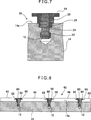
Das Einstellelement
Gemäß der vorliegenden Ausführungsform umfasst das Einstellelement
Gemäß der vorliegenden Ausführungsform kann eine Magnetplatte
Im Folgenden werden verschiedene Ausführungsformen der vorliegenden Erfindung beschrieben, die sich von der voranstehend beschriebenen Ausführungsform unterscheiden. Bereits beschriebene Sachverhalte werden zur Vermeidung von Wiederholungen nicht erneut beschrieben. Dieselben oder entsprechende Komponenten werden mit den gleichen Bezugszeichen versehen.In the following, various embodiments of the present invention will be described, which differ from the embodiment described above. Facts already described are not described again to avoid repetition. The same or corresponding components are given the same reference numerals.
Wie dargestellt ist, haben die Einstellelemente
Obwohl konkrete Beispiele für die Umsetzung der vorliegenden Erfindung beschrieben wurden, ist es für einen Fachmann ersichtlich, dass die vorliegende Erfindung in jeder Kombination der Ausführungsformen und/oder der hier explizit oder implizit offenbarten Ausführungsbeispiele umgesetzt werden kann.Although specific examples of the implementation of the present invention have been described It will be apparent to those skilled in the art that the present invention can be implemented in any combination of the embodiments and / or the embodiments explicitly or implicitly disclosed herein.
Effekt der ErfindungEffect of the invention
Gemäß der ersten Ausführungsform der Erfindung kann eine Fehlausrichtung der Permanentmagnete an der Platte durch die abschnittsweise von der Platte vorstehenden Einstellelemente verhindert werden. Da die Einstellelemente aus einem härteren Material als dem Material der Platte hergestellt sind, durchläuft die Platte eine plastische Deformation beim Einpressen der Einstellelemente. Ferner wird durch den verkleinerten Abschnitt sowie durch den vergrößerten Abschnitt des Einstellelements ein Abschnitt der Platte, der die plastische Deformation durchläuft, in den Freiraum zwischen dem verkleinerten Abschnitt des Einstellelements und der Sacköffnung bewegt. Dies lässt ein Vorsehen des Einstellelements an der Platte mit einer ausreichend hohen strukturellen Festigkeit ohne Zuhilfenahme von Schneidverfahren zu, die die Herstellungskosten erhöhen. Mit dem in die Sacköffnung eingepressten Einstellelement kann ein Eindringen einer Flüssigkeit, wie z. B. einer Schneidflüssigkeit, in die Sacköffnung von der entgegengesetzten Seite der Platte verhindert werden. Eine betriebssichere Magnetplatte kann somit bereitgestellt werden.According to the first embodiment of the invention, misalignment of the permanent magnets on the plate can be prevented by the section-wise protruding members from the plate. Since the adjusting elements are made of a harder material than the material of the plate, the plate undergoes a plastic deformation during the pressing of the adjusting elements. Further, through the reduced portion and the enlarged portion of the adjusting member, a portion of the plate undergoing the plastic deformation is moved into the clearance between the reduced portion of the adjusting member and the bag mouth. This allows for providing the adjusting member to the plate with a sufficiently high structural strength without the aid of cutting methods that increase the manufacturing cost. With the pressed-in the sack opening adjustment can penetrate a liquid such. As a cutting fluid to be prevented in the bag opening from the opposite side of the plate. A reliable magnetic disk can thus be provided.
Gemäß der zweiten Ausführungsform der Erfindung haben die Einstellelemente eine zylindrische Form und somit kann ein Verfahren zum Einpressen der Einstellelemente in die Sacköffnungen erleichtert werden. Zudem können die Einstellelemente kostengünstig hergestellt werden.According to the second embodiment of the invention, the adjusting members have a cylindrical shape, and thus a method for pressing the adjusting members into the blind holes can be facilitated. In addition, the adjustment can be made inexpensively.
Gemäß der dritten Ausführungsform der Erfindung haben die Einstellelemente eine längliche Form, die sich entlang der Längsrichtung der Permanentmagnete erstreckt. Dies verhindert die Fehlausrichtung der Permanentmagnete über einen breiteren Bereich entlang der Längsrichtung der Permanentmagnete und somit kann ein größerer Effekt der Verhinderung der Fehlausrichtung erreicht werden. Ferner kann die Befestigungskraft zwischen dem Einstellelement und der Sacköffnung über einen breiteren Bereich entlang der Längsrichtung des Permanentmagnets bereitgestellt werden und somit eine unvorhersehbare Bewegung des Einstellelements verhindert werden.According to the third embodiment of the invention, the adjusting members have an elongated shape extending along the longitudinal direction of the permanent magnets. This prevents the misalignment of the permanent magnets over a wider area along the longitudinal direction of the permanent magnets, and thus a larger effect of preventing the misalignment can be achieved. Further, the fastening force between the adjusting member and the bag mouth can be provided over a wider range along the longitudinal direction of the permanent magnet, thus preventing unpredictable movement of the adjusting member.
Gemäß der vierten Ausführungsform der Erfindung dient die geneigte Fläche des Einstellelements als Führung zum Führen der Permanentmagnete, wenn die Permanentmagnete in einer Richtung senkrecht zur Fläche der Platte vorgesehen werden. Somit kann das Verfahren zum Anbringen der Permanentmagnete erleichtert werden.According to the fourth embodiment of the invention, the inclined surface of the adjusting member serves as a guide for guiding the permanent magnets when the permanent magnets are provided in a direction perpendicular to the surface of the disk. Thus, the method of attaching the permanent magnets can be facilitated.
Gemäß der fünften Ausführungsform der Erfindung mit dem an der vorstehenden Fläche der Einstellelemente ausgebildeten konvexen Abschnitt und konkaven Abschnitt wird das Harz an der Fläche vorgesehen, die durch den konkaven Abschnitt und den konvexen Abschnitt definiert wird, so dass der Flächenbereich vergrößert wird, an dem das Harz und das Einstellelement miteinander in Kontakt sind. Somit kann das Ablösen des Harzes von dem Einstellelement verhindert werden, und eine betriebssichere Magnetplatte bereitgestellt werden.According to the fifth embodiment of the invention, with the convex portion and the concave portion formed on the protruding surface of the adjusting members, the resin is provided on the surface defined by the concave portion and the convex portion, so as to increase the area at which the Resin and the adjusting element are in contact with each other. Thus, peeling of the resin from the adjusting member can be prevented, and a fail-safe magnetic disk can be provided.
Gemäß der sechsten Ausführungsform der Erfindung umfasst das Einstellelement einen Flanschabschnitt, der sich über die Seitenkanten des Permanentmagnets hinaus erstreckt. Der Flanschabschnitt dient als Führung, wenn die Permanentmagnete in einer Richtung parallel zu der Fläche der Platte angebracht werden. Der Flanschabschnitt verhindert ebenfalls eine Bewegung der Permanentmagnete in einer Richtung senkrecht zu der Fläche der Platte. Somit kann eine Fehlausrichtung des Permanentmagnets nicht nur in einer Richtung parallel zu der Fläche der Platte, sondern auch in einer Richtung senkrecht dazu verhindert werden.According to the sixth embodiment of the invention, the adjustment member includes a flange portion that extends beyond the side edges of the permanent magnet. The flange portion serves as a guide when the permanent magnets are mounted in a direction parallel to the surface of the plate. The flange portion also prevents movement of the permanent magnets in a direction perpendicular to the surface of the plate. Thus, misalignment of the permanent magnet can be prevented not only in a direction parallel to the face of the plate but also in a direction perpendicular thereto.
Gemäß der siebten Ausführungsform der Erfindung mit den Permanentmagneten mit einer sich von der Fläche der Platte weg erstreckenden Form kann die von dem Zusammenwirken zwischen der Armatur und der Magnetplatte erzeugte Antriebskraft mit hoher Präzision gesteuert werden. Dementsprechend kann die Bewegung eines Motors eines Elektromotors mit hoher Präzision gesteuert werden.According to the seventh embodiment of the invention, with the permanent magnets having a shape extending away from the surface of the plate, the driving force generated by the cooperation between the armature and the magnetic disk can be controlled with high precision. Accordingly, the movement of a motor of an electric motor can be controlled with high precision.
Obwohl die Erfindung mit beispielhaften Ausführungsformen dargestellt und beschrieben wurde, ist es für einen Fachmann verständlich, dass die voranstehenden und weitere Veränderungen, Weglassungen, und Zusätze vorgenommen werden kann, ohne sich vom Schutzbereich der Erfindung zu entfernen.Although the invention has been illustrated and described with exemplary embodiments, it will be understood by those skilled in the art that the foregoing and other changes, omissions, and additions may be made without departing from the scope of the invention.
ZITATE ENTHALTEN IN DER BESCHREIBUNG QUOTES INCLUDE IN THE DESCRIPTION
Diese Liste der vom Anmelder aufgeführten Dokumente wurde automatisiert erzeugt und ist ausschließlich zur besseren Information des Lesers aufgenommen. Die Liste ist nicht Bestandteil der deutschen Patent- bzw. Gebrauchsmusteranmeldung. Das DPMA übernimmt keinerlei Haftung für etwaige Fehler oder Auslassungen.This list of the documents listed by the applicant has been generated automatically and is included solely for the better information of the reader. The list is not part of the German patent or utility model application. The DPMA assumes no liability for any errors or omissions.
Zitierte PatentliteraturCited patent literature
- JP 2564851 B [0002] JP 2564851 B [0002]
- JP 9-511380 A [0002] JP 9-511380A [0002]
- JP 2010-120055 A [0002] JP 2010-120055 A [0002]
Claims (7)
Applications Claiming Priority (2)
| Application Number | Priority Date | Filing Date | Title |
|---|---|---|---|
| JP2012-062663 | 2012-03-19 | ||
| JP2012062663A JP5438159B2 (en) | 2012-03-19 | 2012-03-19 | Magnet plate for linear motor having action to prevent magnet position shift |
Publications (2)
| Publication Number | Publication Date |
|---|---|
| DE102013004322A1 true DE102013004322A1 (en) | 2013-09-19 |
| DE102013004322B4 DE102013004322B4 (en) | 2021-09-16 |
Family
ID=49044067
Family Applications (1)
| Application Number | Title | Priority Date | Filing Date |
|---|---|---|---|
| DE102013004322.0A Expired - Fee Related DE102013004322B4 (en) | 2012-03-19 | 2013-03-12 | Magnetic plate for a linear motor to prevent misalignment of magnets |
Country Status (4)
| Country | Link |
|---|---|
| US (1) | US9806579B2 (en) |
| JP (1) | JP5438159B2 (en) |
| CN (2) | CN203243202U (en) |
| DE (1) | DE102013004322B4 (en) |
Families Citing this family (8)
| Publication number | Priority date | Publication date | Assignee | Title |
|---|---|---|---|---|
| JP5438159B2 (en) * | 2012-03-19 | 2014-03-12 | ファナック株式会社 | Magnet plate for linear motor having action to prevent magnet position shift |
| EP3232550A1 (en) * | 2016-04-12 | 2017-10-18 | Robert Bosch Gmbh | Secondary part of a linear motor |
| EP3392512A1 (en) | 2017-04-19 | 2018-10-24 | HILTI Aktiengesellschaft | Fastening method and fastening system |
| JP6705774B2 (en) | 2017-06-19 | 2020-06-03 | ファナック株式会社 | Magnet plate mounting structure |
| JP2019009883A (en) | 2017-06-23 | 2019-01-17 | ファナック株式会社 | Magnet plate for linear motor and linear motor |
| CN109038968B (en) * | 2018-08-20 | 2020-05-19 | 宁波菲仕技术股份有限公司 | Method for manufacturing magnetic steel fixing plate of linear motor |
| CN112018928B (en) * | 2019-05-31 | 2023-06-27 | 日本电产株式会社 | Motor and electric device comprising same |
| WO2024013987A1 (en) * | 2022-07-15 | 2024-01-18 | ファナック株式会社 | Linear motor magnet plate |
Citations (3)
| Publication number | Priority date | Publication date | Assignee | Title |
|---|---|---|---|---|
| JP2564851B2 (en) | 1987-10-02 | 1996-12-18 | 神鋼電機株式会社 | Field structure of linear DC brushless motor |
| JPH09511380A (en) | 1995-02-03 | 1997-11-11 | クラウス−マツフアイ アクチエンゲゼルシヤフト | Synchronous linear motor |
| JP2010120055A (en) | 2008-11-20 | 2010-06-03 | Edl Kk | Flange assembly having hollow shaft, developing roller, flat-plate-like member with shaft, roller member and method of manufacturing flange assembly having hollow shaft |
Family Cites Families (16)
| Publication number | Priority date | Publication date | Assignee | Title |
|---|---|---|---|---|
| US3571903A (en) * | 1968-12-13 | 1971-03-23 | Ibm | Method of securing a self-piercing and clinching element to a sheet of metal |
| US3783313A (en) * | 1972-06-29 | 1974-01-01 | Canadian Patents Dev | Electrical stepping motors having low inertia rotors |
| GB1471666A (en) * | 1973-07-19 | 1977-04-27 | Ocean Investments Ltd | Method and fastener for use in joining together an assembly of metal sheets |
| JPH0442743A (en) * | 1990-06-05 | 1992-02-13 | Fanuc Ltd | Rotor structure for synchronous motor |
| JPH0919091A (en) * | 1995-06-30 | 1997-01-17 | Fanuc Ltd | Rotor for synchronous motor |
| US5757091A (en) * | 1995-07-03 | 1998-05-26 | Fanuc Ltd. | Permanent magnet field pole for linear motor |
| JPH10318229A (en) | 1997-05-15 | 1998-12-02 | Chofu Seisakusho Co Ltd | Positioning pin for resin molded product and method of molding resin molded product using the same positioning pin |
| JP2004015873A (en) * | 2002-06-04 | 2004-01-15 | Tamagawa Seiki Co Ltd | Rotor structure for rotary motor |
| JP3848596B2 (en) * | 2002-06-11 | 2006-11-22 | ファナック株式会社 | Linear motor |
| EP1780870B1 (en) * | 2004-07-16 | 2018-09-05 | Mitsuba Corporation | Magnet fixing structure for electric rotating machine |
| JP2006174583A (en) * | 2004-12-15 | 2006-06-29 | Fanuc Ltd | Linear motor |
| EP1968175A3 (en) * | 2007-03-08 | 2015-10-28 | Sanyo Denki Co., Ltd. | Linear motor with reduced cogging |
| US8328489B2 (en) * | 2007-12-17 | 2012-12-11 | Acument Intellectual Properties, Llc | Self-pierce rivets and an adjustable strap handle |
| US7781932B2 (en) * | 2007-12-31 | 2010-08-24 | General Electric Company | Permanent magnet assembly and method of manufacturing same |
| US8297899B2 (en) * | 2009-10-23 | 2012-10-30 | Pem Management, Inc. | Clinch pin fastener |
| JP5438159B2 (en) * | 2012-03-19 | 2014-03-12 | ファナック株式会社 | Magnet plate for linear motor having action to prevent magnet position shift |
-
2012
- 2012-03-19 JP JP2012062663A patent/JP5438159B2/en not_active Expired - Fee Related
-
2013
- 2013-02-28 US US13/780,959 patent/US9806579B2/en not_active Expired - Fee Related
- 2013-03-12 DE DE102013004322.0A patent/DE102013004322B4/en not_active Expired - Fee Related
- 2013-03-18 CN CN201320123082XU patent/CN203243202U/en not_active Expired - Lifetime
- 2013-03-18 CN CN201310085638.5A patent/CN103326535B/en not_active Expired - Fee Related
Patent Citations (3)
| Publication number | Priority date | Publication date | Assignee | Title |
|---|---|---|---|---|
| JP2564851B2 (en) | 1987-10-02 | 1996-12-18 | 神鋼電機株式会社 | Field structure of linear DC brushless motor |
| JPH09511380A (en) | 1995-02-03 | 1997-11-11 | クラウス−マツフアイ アクチエンゲゼルシヤフト | Synchronous linear motor |
| JP2010120055A (en) | 2008-11-20 | 2010-06-03 | Edl Kk | Flange assembly having hollow shaft, developing roller, flat-plate-like member with shaft, roller member and method of manufacturing flange assembly having hollow shaft |
Also Published As
| Publication number | Publication date |
|---|---|
| DE102013004322B4 (en) | 2021-09-16 |
| CN103326535A (en) | 2013-09-25 |
| CN203243202U (en) | 2013-10-16 |
| US20130241319A1 (en) | 2013-09-19 |
| US9806579B2 (en) | 2017-10-31 |
| JP2013198278A (en) | 2013-09-30 |
| JP5438159B2 (en) | 2014-03-12 |
| CN103326535B (en) | 2016-12-28 |
Similar Documents
| Publication | Publication Date | Title |
|---|---|---|
| DE102013004322B4 (en) | Magnetic plate for a linear motor to prevent misalignment of magnets | |
| DE102013002354A1 (en) | ROTOR OF AN ELECTRIC ENGINE THAT HAS A CONSTRUCTION FOR THE SAFE APPLICATION OF MAGNETS TO AN EXTERNAL CIRCULAR SURFACE OF A ROTOR CORE, AND METHOD OF MANUFACTURING THEREOF | |
| DE102012221422A1 (en) | Rotor of an electric motor and method of manufacturing the rotor | |
| DE102008043488A1 (en) | Shaft hub component producing method for armature of electrical machine of vehicle, involves joining shaft and hub components to shaft component, where hardness of hub components is smaller than layer hardness of shaft | |
| DE2911874A1 (en) | ELECTROMAGNETIC COUPLING AND METHOD OF MANUFACTURING IT | |
| DE102007063307A1 (en) | Assembly method for fitting a permanent magnet in a holding element | |
| DE102017119389B4 (en) | Electromagnetic brake | |
| DE112016002264T5 (en) | ROTOR, ELECTRICAL ROTATION MACHINE AND METHOD FOR PRODUCING A ROTOR | |
| DE102020214664A1 (en) | ROTOR OF AN AXIAL FLOW MOTOR | |
| WO2005114813A1 (en) | Laminated core produced from segments | |
| WO2003005531A1 (en) | Permanent-magnetic rotor | |
| DE102020103868A1 (en) | Rotor and method of making a rotor | |
| DE602004007333T2 (en) | Method for producing an armature for an electric machine and armature produced by the method | |
| DE102014216743A1 (en) | Electric machine | |
| EP2144350A2 (en) | Rotor for an electric motor and method for its production | |
| DE102019117834A1 (en) | Electrical or electronic assemblies and methods for manufacturing an electrical or electronic component | |
| DE102012101396B3 (en) | Device for resilient coupling flange to structure used in oscillation damper, has stop whose axial extent is more than spacing between retention surfaces and holding frame supporting surface over which locking elements are distributed | |
| EP1234122B1 (en) | Armature for an electric machine | |
| DE102014003181B4 (en) | Method for connecting at least two components and connection arrangement | |
| DE102005002332A1 (en) | Rotor for permanently excited electric machine e.g. electric drive motor of motor vehicle has magnets held in grooves of rotor by press fit whereby recess adjacent to the groove is arranged in the area around grooves | |
| DE102009025622A1 (en) | Rotor and method for positioning magnets of a rotor | |
| DE102015008645A1 (en) | Method for connecting two components | |
| DE102013204267A1 (en) | Method for producing a drive unit for an actuator in a motor vehicle and drive unit | |
| DE102010062265A1 (en) | Assembly of a pump housing and a control unit housing and method for producing such a unit | |
| DE102023210982A1 (en) | Rotor for an electric motor, method for mounting a disk pack on a rotor shaft and mounting device |
Legal Events
| Date | Code | Title | Description |
|---|---|---|---|
| R083 | Amendment of/additions to inventor(s) | ||
| R012 | Request for examination validly filed |
Effective date: 20131217 |
|
| R016 | Response to examination communication | ||
| R016 | Response to examination communication | ||
| R018 | Grant decision by examination section/examining division | ||
| R020 | Patent grant now final | ||
| R119 | Application deemed withdrawn, or ip right lapsed, due to non-payment of renewal fee |