DE102012218433A1 - Contact element for contact arrangement, has shoulder portion arranged between contact portion and insertion portion, which is protruded laterally to contact portion and is adapted to introduce pressing force into insertion portion - Google Patents

Contact element for contact arrangement, has shoulder portion arranged between contact portion and insertion portion, which is protruded laterally to contact portion and is adapted to introduce pressing force into insertion portion Download PDF

Info

Publication number
DE102012218433A1
DE102012218433A1 DE201210218433 DE102012218433A DE102012218433A1 DE 102012218433 A1 DE102012218433 A1 DE 102012218433A1 DE 201210218433 DE201210218433 DE 201210218433 DE 102012218433 A DE102012218433 A DE 102012218433A DE 102012218433 A1 DE102012218433 A1 DE 102012218433A1
Authority
DE
Germany
Prior art keywords
contact
section
press
contact element
longitudinal axis
Prior art date
Legal status (The legal status is an assumption and is not a legal conclusion. Google has not performed a legal analysis and makes no representation as to the accuracy of the status listed.)
Granted
Application number
DE201210218433
Other languages
German (de)
Other versions
DE102012218433B4 (en
Inventor
Nikolaus Kerner
Current Assignee (The listed assignees may be inaccurate. Google has not performed a legal analysis and makes no representation or warranty as to the accuracy of the list.)
Schaeffler Technologies AG and Co KG
Original Assignee
Continental Automotive Technologies GmbH
Priority date (The priority date is an assumption and is not a legal conclusion. Google has not performed a legal analysis and makes no representation as to the accuracy of the date listed.)
Filing date
Publication date
Application filed by Continental Automotive Technologies GmbH filed Critical Continental Automotive Technologies GmbH
Priority to DE102012218433.3A priority Critical patent/DE102012218433B4/en
Publication of DE102012218433A1 publication Critical patent/DE102012218433A1/en
Application granted granted Critical
Publication of DE102012218433B4 publication Critical patent/DE102012218433B4/en
Active legal-status Critical Current
Anticipated expiration legal-status Critical

Links

Images

Classifications

    • HELECTRICITY
    • H01ELECTRIC ELEMENTS
    • H01RELECTRICALLY-CONDUCTIVE CONNECTIONS; STRUCTURAL ASSOCIATIONS OF A PLURALITY OF MUTUALLY-INSULATED ELECTRICAL CONNECTING ELEMENTS; COUPLING DEVICES; CURRENT COLLECTORS
    • H01R43/00Apparatus or processes specially adapted for manufacturing, assembling, maintaining, or repairing of line connectors or current collectors or for joining electric conductors
    • H01R43/20Apparatus or processes specially adapted for manufacturing, assembling, maintaining, or repairing of line connectors or current collectors or for joining electric conductors for assembling or disassembling contact members with insulating base, case or sleeve
    • H01R43/205Apparatus or processes specially adapted for manufacturing, assembling, maintaining, or repairing of line connectors or current collectors or for joining electric conductors for assembling or disassembling contact members with insulating base, case or sleeve with a panel or printed circuit board
    • HELECTRICITY
    • H01ELECTRIC ELEMENTS
    • H01RELECTRICALLY-CONDUCTIVE CONNECTIONS; STRUCTURAL ASSOCIATIONS OF A PLURALITY OF MUTUALLY-INSULATED ELECTRICAL CONNECTING ELEMENTS; COUPLING DEVICES; CURRENT COLLECTORS
    • H01R12/00Structural associations of a plurality of mutually-insulated electrical connecting elements, specially adapted for printed circuits, e.g. printed circuit boards [PCB], flat or ribbon cables, or like generally planar structures, e.g. terminal strips, terminal blocks; Coupling devices specially adapted for printed circuits, flat or ribbon cables, or like generally planar structures; Terminals specially adapted for contact with, or insertion into, printed circuits, flat or ribbon cables, or like generally planar structures
    • H01R12/50Fixed connections
    • H01R12/51Fixed connections for rigid printed circuits or like structures
    • H01R12/55Fixed connections for rigid printed circuits or like structures characterised by the terminals
    • H01R12/58Fixed connections for rigid printed circuits or like structures characterised by the terminals terminals for insertion into holes
    • H01R12/585Terminals having a press fit or a compliant portion and a shank passing through a hole in the printed circuit board
    • HELECTRICITY
    • H05ELECTRIC TECHNIQUES NOT OTHERWISE PROVIDED FOR
    • H05KPRINTED CIRCUITS; CASINGS OR CONSTRUCTIONAL DETAILS OF ELECTRIC APPARATUS; MANUFACTURE OF ASSEMBLAGES OF ELECTRICAL COMPONENTS
    • H05K2201/00Indexing scheme relating to printed circuits covered by H05K1/00
    • H05K2201/10Details of components or other objects attached to or integrated in a printed circuit board
    • H05K2201/10227Other objects, e.g. metallic pieces
    • H05K2201/10295Metallic connector elements partly mounted in a hole of the PCB
    • H05K2201/10303Pin-in-hole mounted pins
    • HELECTRICITY
    • H05ELECTRIC TECHNIQUES NOT OTHERWISE PROVIDED FOR
    • H05KPRINTED CIRCUITS; CASINGS OR CONSTRUCTIONAL DETAILS OF ELECTRIC APPARATUS; MANUFACTURE OF ASSEMBLAGES OF ELECTRICAL COMPONENTS
    • H05K3/00Apparatus or processes for manufacturing printed circuits
    • H05K3/30Assembling printed circuits with electric components, e.g. with resistors
    • H05K3/306Assembling printed circuits with electric components, e.g. with resistors with lead-in-hole components
    • H05K3/308Adaptations of leads

Landscapes

  • Engineering & Computer Science (AREA)
  • Manufacturing & Machinery (AREA)
  • Coupling Device And Connection With Printed Circuit (AREA)

Abstract

Es wird eine Kontaktanordnung 10 und ein Kontaktelement 15, 20 für solch eine Kontaktanordnung 10 angegeben, wobei das Kontaktelement 15, 20 einen an einem ersten Längsende angeordneten Einpressabschnitt 40 aufweist, der ausgelegt ist, in die Leiterplatte 21 eingepresst zu werden. Weiterhin weist das Kontaktelement einen Kontaktabschnitt 30 auf, der an einem dem ersten Längsende gegenüberliegenden zweiten Längsende des Kontaktelements 15, 20 angeordnet ist. Insbesondere weist die Kontaktanordnung zudem genau einen Schulterabschnitt 65 auf, der zwischen dem Kontaktabschnitt 30 und dem Einpressabschnitt 40 angeordnet ist, seitlich gegenüber dem Kontaktabschnitt 40 hervorragt und ausgelegt ist, eine Einpresskraft FP in den Einpressabschnitt 40 einzuleiten. A contact arrangement 10 and a contact element 15, 20 are specified for such a contact arrangement 10, wherein the contact element 15, 20 has a press-in section 40 arranged at a first longitudinal end which is designed to be pressed into the circuit board 21. Furthermore, the contact element has a contact section 30, which is arranged at a second longitudinal end of the contact element 15, 20 opposite the first longitudinal end. In particular, the contact arrangement moreover has exactly one shoulder section 65, which is arranged between the contact section 30 and the press-in section 40, protrudes laterally from the contact section 40 and is designed to introduce a press-in force F P into the press-fit section 40.

Figure DE102012218433A1_0001

Description

Die vorliegende Offenbarung betrifft eine Kontaktanordnung und ein Kontaktelement für solch eine Kontaktanordnung, wobei insbesondere das Kontaktelement einen an einem ersten Längsende angeordneten Einpressabschnitt aufweist, der ausgelegt ist, in die Leiterplatte eingepresst zu werden. Weiterhin weist das Kontaktelement insbesondere einen Kontaktabschnitt auf, der an einem dem ersten Längsende gegenüberliegenden zweiten Längsende des Kontaktelements angeordnet ist, und einen Schulterabschnitt, der zwischen dem Kontaktabschnitt und dem Einpressabschnitt angeordnet ist, und seitlich gegenüber dem Kontaktabschnitt hervorragt. The present disclosure relates to a contact arrangement and a contact element for such a contact arrangement, wherein in particular the contact element has a press-fit section arranged at a first longitudinal end which is designed to be pressed into the circuit board. In particular, the contact element has in particular a contact section, which is arranged on a second longitudinal end of the contact element opposite the first longitudinal end, and a shoulder section, which is arranged between the contact section and the press-in section, and protrudes laterally relative to the contact section.

Aus der DE 102 28 450 A1 ist ein Kontaktelement bekannt, das als Einpresskontakt ausgebildet ist, um eine Leiterplattenstruktur einer Leiterplatte zu kontaktieren. Hierzu umfasst das Kontaktelement einen Einpressabschnitt und einen Kontaktabschnitt mit jeweils zwei lateral über den Einpressabschnitt abstehenden Kontaktzungen zur Ausbildung mindestens einer Kontaktstelle auf der Leiterbahnstruktur der Leiterplatte. Durch die Kontaktzungen weist das Kontaktelement quer zu einer Einpressrichtung eine breite Ausbildung auf. From the DE 102 28 450 A1 a contact element is known, which is designed as a press-in contact to contact a printed circuit board structure of a printed circuit board. For this purpose, the contact element comprises a press-in section and a contact section, each with two contact tongues projecting laterally beyond the press-in section, for forming at least one contact point on the conductor track structure of the circuit board. Due to the contact tongues, the contact element has a broad training transversely to a press-in.

Es ist eine Aufgabe der Erfindung, ein schlankes Kontaktelement bereitzustellen. It is an object of the invention to provide a slim contact element.

Diese Aufgabe wird durch ein Kontaktelement mit den Merkmalen des Anspruchs 1 gelöst. Vorteilhafte Ausgestaltungen und Weiterbildungen des Kontaktelements und einer Kontaktanordnung mit einem solchen Kontaktelement sind in den abhängigen Ansprüchen angegeben. This object is achieved by a contact element with the features of claim 1. Advantageous embodiments and further developments of the contact element and a contact arrangement with such a contact element are specified in the dependent claims.

Gemäß einem ersten Aspekt wird ein Kontaktelement angegeben. Das Kontaktelement hat einen an einem ersten Längsende angeordneten Einpressabschnitt, der ausgelegt ist, in die Leiterplatte eingepresst zu werden und einen Kontaktabschnitt, der an einem dem ersten Längsende gegenüberliegenden zweiten Längsende des Kontaktelements angeordnet ist. Zwischen dem Kontaktabschnitt und dem Einpressabschnitt weist das Kontaktelement einen Schulterabschnitt auf. Der Schulterabschnitt ragt seitlich gegenüber dem Kontaktabschnitt hervor. According to a first aspect, a contact element is specified. The contact element has a press-fit portion arranged at a first longitudinal end and adapted to be pressed into the printed circuit board and a contact portion arranged at a second longitudinal end of the contact element opposite the first longitudinal end. Between the contact portion and the press-in portion, the contact element has a shoulder portion. The shoulder portion protrudes laterally relative to the contact portion.

Insbesondere ist das Kontaktelement bezüglich einer vom Kontaktabschnitt zum Einpressabschnitt verlaufenden Gesamtlängsachse asymmetrisch ausgebildet, zum Beispiel in Draufsicht auf diejenige, die Gesamtlängsachse enthaltende Ebene, in der das Kontaktelement die größte Ausdehnung senkrecht zur Gesamtlängsachse hat. Beispielsweise sind die Schwerpunkte von Kontaktabschnitt und Einpressabschnitt von der Längsachse beabstandet, insbesondere in entgegengesetzten Richtungen. In particular, the contact element is formed asymmetrically with respect to a total longitudinal axis extending from the contact section to the press-in section, for example in plan view of the plane containing the overall longitudinal axis, in which the contact element has the greatest extent perpendicular to the overall longitudinal axis. For example, the focal points of the contact portion and press-in portion are spaced from the longitudinal axis, in particular in opposite directions.

Vorzugsweise ist bei dem Kontaktelement ausschließlich nur ein Schulterabschnitt vorgesehen, der ausgelegt ist, eine Einpresskraft in den Einpressabschnitt einzuleiten. Mit anderen Worten weist das Kontaktelement genau einen Schulterabschnitt zwischen dem Kontaktabschnitt und dem Einpressabschnitt auf, der seitlich gegenüber dem Kontaktabschnitt hervorragt und dazu ausgebildet ist, eine Einpresskraft auf den Einpressabschnitt zu übertragen. Bevorzugt ist der genau eine Schulterabschnitt dazu vorgesehen, mit einem Einpresswerkzeug zusammenzuwirken um den Einpressabschnitt mittels der Einpresskraft in eine Leiterplatte einzupressen. Preferably, only one shoulder portion is provided in the contact element, which is designed to initiate a press-in force in the press-fit. In other words, the contact element has exactly one shoulder section between the contact section and the press-in section, which protrudes laterally from the contact section and is designed to transmit a press-in force to the press-in section. Preferably, exactly one shoulder portion is provided to cooperate with a press-fit tool to press the press-in portion by means of the press-fit force into a printed circuit board.

Auf diese Weise kann ein schmal ausgebildetes Kontaktelement bereitgestellt werden, das auf einfache Weise zur Bereitstellung einer Kontaktierung mit einer Leiterplattenstruktur der Leiterplatte in eine Leiterplatte eingepresst werden kann. Mit Vorteil kann auf diese Weise eine besonders große Anzahl von Kontaktelementen nebeneinander innerhalb eines vordefinierten Abschnitts in eine Leiterplatte eingepresst werden. In this way, a narrow contact element can be provided, which can be pressed in a simple manner to provide a contact with a printed circuit board structure of the printed circuit board in a printed circuit board. Advantageously, in this way a particularly large number of contact elements can be pressed next to one another within a predefined section into a printed circuit board.

Bei einer Ausgestaltung weist der Kontaktabschnitt eine erste Längsachse auf und der Einpressabschnitt weist eine zweite Längsachse auf. Die erste und die zweite Längsachse sind vorzugsweise parallel zur Einpressrichtung des Kontaktelements ausgerichtet. Die Einpressrichtung ist insbesondere parallel zur Gesamtlängsachse. Bei einer Ausgestaltung ist, in Draufsicht auf eine Haupterstreckungsebene des Kontaktelements, der Kontaktabschnitt spiegelsymmetrisch zur ersten Längsachse und/oder der Einpressabschnitt ist spiegelsymmetrisch zur zweiten Längsachse. Die Haupterstreckungsebene enthält insbesondere die erste und die zweite Längsachse. In one embodiment, the contact portion has a first longitudinal axis and the press-in portion has a second longitudinal axis. The first and the second longitudinal axis are preferably aligned parallel to the pressing-in direction of the contact element. The press-in direction is in particular parallel to the overall longitudinal axis. In one embodiment, in a plan view of a main extension plane of the contact element, the contact section is mirror-symmetrical to the first longitudinal axis and / or the press-fit section is mirror-symmetrical to the second longitudinal axis. The main extension plane contains in particular the first and the second longitudinal axis.

Der Kontaktabschnitt ist derart gegenüber dem Einpressabschnitt angeordnet, dass die erste Längsachse versetzt zu der zweiten Längsachse angeordnet ist. Vorzugsweise ist die zweite Längsachse gegenüber der ersten Längsachse in diejenige Richtung versetzt, in der der Schulterabschnitt über den Kontaktabschnitt hinausragt. Mit Vorteil kann so eine Einpresskraft im Wesentlichen parallel zur Einpressrichtung in den Einpressabschnitt eingebracht werden. Obwohl die Einpresskraft insbesondere nur an dem genau einen Schulterabschnitt angreift kann auf diese Weise das auf den Einpressabschnitt ausgeübte Drehmoment minimiert werden, so dass die Gefahr eines Verkippens des Kontaktelement beim Einpressen besonders gering ist. The contact portion is arranged opposite the press-in portion such that the first longitudinal axis is offset from the second longitudinal axis. Preferably, the second longitudinal axis is offset relative to the first longitudinal axis in the direction in which the shoulder portion projects beyond the contact portion. Advantageously, such a press-in force can be introduced into the press-in section essentially parallel to the press-fit direction. Although the press-in force engages in particular only on the exactly one shoulder portion, in this way the torque exerted on the press-fit portion can be minimized, so that the risk of tilting of the contact element during pressing in is particularly low.

Bei einer Ausgestaltung weist das Kontaktelement einen Mittelabschnitt auf, der den Schulterabschnitt enthält. Beispielsweise ragen der Kontaktabschnitt und der Einpressabschnitt in Längsrichtung an gegenüberliegenden Seiten aus dem Mittelabschnitt heraus. In one embodiment, the contact element has a central portion, which the Shoulder section contains. For example, the contact portion and the press-in portion protrude longitudinally on opposite sides out of the central portion.

Bei einer weiteren Ausgestaltung ist eine erste Seitenfläche gegenüberliegend zum Schulterabschnitt seitlich am Mittelabschnitt und am Kontaktabschnitt vorgesehen, wobei die erste Seitenfläche sich zumindest teilweise durchgehend – insbesondere flach, d.h. ohne Stufen oder Knicke – über den Kontaktabschnitt und zumindest teilweise über den Mittelabschnitt erstreckt. Dies hat den Vorteil, dass ein Werkzeug zum Ausstanzen des Kontaktelements eine besonders einfache Kontur aufweist. Eine solche flache Seitenfläche ist auch im Hinblick auf die Verringerung der Gefahr von elektrischen Überschlägen oder Kurzschlüssen zwischen seitlich benachbarten Kontaktelementen vorteilhaft. In a further embodiment, a first side surface opposite the shoulder portion is provided laterally at the central portion and at the contact portion, the first side surface being at least partially continuous, in particular flat, i. without steps or kinks - extends over the contact portion and at least partially over the middle portion. This has the advantage that a tool for punching the contact element has a particularly simple contour. Such a flat side surface is also advantageous in terms of reducing the risk of electrical flashovers or short circuits between laterally adjacent contact elements.

Bei einer vorteilhaften Weiterbildung erstreckt sich die erste Seitenfläche über den Kontaktabschnitt und den Mittelabschnitt in einer Ebene, die parallel zu der ersten und/oder der zweiten Längsachse ausgerichtet ist. Das Einschieben des Kontaktelements in einen Trägerkörper benötigt auf diese Weise besonders wenig Kraft. In an advantageous development, the first side surface extends over the contact portion and the middle portion in a plane which is aligned parallel to the first and / or the second longitudinal axis. The insertion of the contact element in a carrier body requires in this way very little force.

Bei einer weiteren Ausgestaltung ist der Einpressabschnitt in Längsrichtung, d.h. in Richtung der ersten und/oder der zweiten Längsachse, zumindest teilweise unterhalb des Schulterabschnitts angeordnet. So kann eine Erstreckung des Kontaktelements quer zur ersten bzw. zweiten Längsachse minimiert sein. Auf diese Weise ist ein besonders schlankes Kontaktelement erzielbar. Zudem ist auf diese Weise die Gefahr besonders gering, dass das Kontaktelement beim Einpressen verkippt. In a further embodiment, the press-in section is longitudinal, i. in the direction of the first and / or the second longitudinal axis, at least partially disposed below the shoulder portion. Thus, an extension of the contact element transversely to the first or second longitudinal axis can be minimized. In this way, a particularly slim contact element can be achieved. In addition, the risk is particularly low in this way that the contact element tilted during pressing.

Bei einer weiteren Ausgestaltung umfasst der Schulterabschnitt eine Anlagefläche, insbesondere eine Anlagefläche für ein Einpresswerkzeug. Die Anlagefläche ist auf einer dem Kontaktabschnitt zugewandten Seite des Schulterabschnitts angeordnet. Der Einpressabschnitt ist in diesem Fall vorzugsweise zumindest teilweise in Richtung der zweiten Längsachse unterhalb der Anlagefläche und angrenzend an den Schulterabschnitt angeordnet. Anders ausgedrückt überlappen die Anlagefläche und der Einpressabschnitt in Draufsicht entlang der Längsrichtung zumindest teilweise. Auf diese Weise kann ein besonders günstiger Kraftverlauf von einem oberhalb des Schulterabschnitts angeordneten Einpresswerkzeug in den unterhalb des Schulterabschnitts angeordneten Einpressabschnitt erzielt werden. In a further embodiment, the shoulder portion comprises a contact surface, in particular a contact surface for a press tool. The contact surface is arranged on a contact portion facing side of the shoulder portion. In this case, the press-in section is preferably arranged at least partially in the direction of the second longitudinal axis below the contact surface and adjacent to the shoulder section. In other words, the contact surface and the press-in section overlap at least partially in plan view along the longitudinal direction. In this way, a particularly favorable force curve can be achieved by an injection tool arranged above the shoulder section in the press-in section arranged below the shoulder section.

Bei einer Ausgestaltung ist an dem Schulterabschnitt eine gegenüberliegend zur ersten Seitenfläche angeordnete zweite Seitenfläche vorgesehen, die sich zum Beispiel parallel zur Gesamtlängsachse erstreckt. Der Einpressabschnitt hat eine dritte Seitenfläche, die dem Schulterabschnitt zugewandt ist. Die dritte Seitenfläche ist in Richtung quer – insbesondere senkrecht – zur zweiten Längsachse beabstandet zur zweiten Seitenfläche des Schulterabschnitts angeordnet, und zwar insbesondere derart, dass der Schulterabschnitt über die dritte Seitenfläche hinaus ragt. In one embodiment, a second side surface arranged opposite the first side surface is provided on the shoulder portion, which extends, for example, parallel to the overall longitudinal axis. The press-fit portion has a third side surface facing the shoulder portion. The third side surface is arranged transversely-in particular perpendicularly-spaced from the second longitudinal axis to the second side surface of the shoulder portion, in particular such that the shoulder portion protrudes beyond the third side surface.

Bei einer Ausgestaltung ist wenigstens ein Verankerungsabschnitt vorgesehen, der im Mittelabschnitt und/oder im Schulterabschnitt angeordnet ist. Der Verankerungsabschnitt ist beispielsweise durch Verankerungselemente gebildet, die in dem Mittelabschnitt bzw. Schulterabschnitt ausgebildet sind. Mittels der Verankerungselemente kann beispielsweise eine sägezahnförmige Oberflächenkontur des Verankerungsabschnitts geformt sein. Beispielsweise ist wenigstens ein Verankerungsabschnitt an der ersten und/oder zweiten Seitenfläche angeordnet. Mit dem Verankerungsabschnitt kann eine besonders gute Verbindung zwischen dem Trägerkörper und dem Kontaktelement erzielt werden. In one embodiment, at least one anchoring section is provided, which is arranged in the middle section and / or in the shoulder section. The anchoring portion is formed, for example, by anchoring elements, which are formed in the central portion or shoulder portion. By means of the anchoring elements, for example, a sawtooth-shaped surface contour of the anchoring section can be formed. For example, at least one anchoring portion is arranged on the first and / or second side surface. With the anchoring portion, a particularly good connection between the carrier body and the contact element can be achieved.

Bei einer Ausgestaltung ist das Kontaktelement aus einem Flachmaterial – zum Beispiel einem Blech – hergestellt, insbesondere ausgestanzt. Die Herstellung des Kontaktelements ist so besonders kostengünstig. In one embodiment, the contact element made of a flat material - for example, a sheet - made, in particular punched out. The production of the contact element is so particularly inexpensive.

Gemäß einem zweiten Aspekt wird eine Kontaktanordnung angegeben. Die Kontaktanordnung weist ein erstes Kontaktelement, wenigstens ein zweites Kontaktelement und einem Trägerkörper auf oder besteht aus diesen Teilen. Das erste und/oder das wenigstens eine zweite Kontaktelement ist gemäß zumindest einer der vorstehend beschriebenen Ausgestaltungen ausgebildet. Das erste und das zweite Kontaktelement bzw. die zweiten Kontaktelemente sind nebeneinander im Trägerkörper angeordnet. Beispielsweise sind die Kontaktelemente in einer Ebene angeordnet, genauer sind insbesondere ihre Gesamtlängsachsen in einer gemeinsamen Ebene enthalten. Vorzugsweise sind die Gesamtlängsachsen der Kontaktelemente zueinander parallel ausgerichtet. According to a second aspect, a contact arrangement is specified. The contact arrangement has a first contact element, at least one second contact element and a carrier body or consists of these parts. The first and / or the at least one second contact element is formed according to at least one of the embodiments described above. The first and the second contact element or the second contact elements are arranged side by side in the carrier body. For example, the contact elements are arranged in a plane, more precisely, in particular, their overall longitudinal axes are contained in a common plane. Preferably, the overall longitudinal axes of the contact elements are aligned parallel to each other.

Bei dem Trägerkörper handelt es sich beispielsweise um eine Trägerplatte, um eine Trägerwanne oder um ein anders geformtes Gehäuse. Der Trägerkörper ist insbesondere dazu vorgesehen, die Kontaktelemente – z.B. vor dem Einpressen oder vor und während des Einpressens in eine Leiterplatte – an vorgegebenen Positionen zueinander zu fixieren. Bei einer zweckmäßigen Ausgestaltung ist der Trägerkörper elektrisch isolierend. The support body is, for example, a support plate, a support trough or a differently shaped housing. The carrier body is particularly intended to provide the contact elements - e.g. before pressing in or before and during pressing in a circuit board - to fix at predetermined positions to each other. In an expedient embodiment, the carrier body is electrically insulating.

Bei einer zweckmäßigen Weiterbildung der Kontaktanordnung ist dem Schulterabschnitt des zweiten Kontaktelements bzw. eines der zweiten Kontaktelemente die erste Seitenfläche des ersten Kontaktelements gegenüberliegend zugewandt. Auf diese Weise können die beiden Kontaktelemente besonders eng zueinander angeordnet werden und brauchen somit nur einen geringen Bauraum, so dass in einem vordefinierten Abschnitt eine höhere Anzahl von Kontaktelementen angeordnet werden kann. Gleichzeitig ist dabei – insbesondere aufgrund der asymmetrischen Ausgestaltung von mindestens einem der Kontaktelemente und der vorzugsweise flachen ersten Seitenfläche – die Gefahr von Kurzschlüssen oder elektrischen Überschlägen besonders gering. In an expedient development of the contact arrangement is the shoulder portion of the second contact element or one of the second Contact elements facing the first side surface of the first contact element opposite. In this way, the two contact elements can be arranged particularly close to each other and thus need only a small space, so that in a predefined section, a higher number of contact elements can be arranged. At the same time - especially due to the asymmetrical design of at least one of the contact elements and the preferably flat first side surface - the risk of short circuits or electrical flashovers is particularly low.

Bei einer Ausgestaltung umgreift der Trägerkörper umfangsseitig das erste und das mindestens eine zweite Kontaktelement zumindest teilweise im Bereich des Schulterabschnitts bzw. im Bereich des Schulterabschnitts und des Mittelabschnitts. Der Trägerkörper hat eine in Richtung des Kontaktabschnitts gewandte Oberseite. Die vom Einpressabschnitt abgewandte und dem Kontaktabschnitt zugewandte Anlagefläche des Schulterabschnitts zum Anliegen eines Einpresswerkzeugs ist mit Vorteil zu der Oberseite beabstandet angeordnet. Anders ausgedrückt ragt der Schulterabschnitt in Längsrichtung vom Einpressabschnitt weg über den Trägerkörper – oder zumindest über einen Bereich des Trägerkörpers, der das Kontaktelement in lateraler Richtung unmittelbar umgibt – hinaus. Auf diese Weise ist die Gefahr besonders gering, dass beim Einpressen der Kontaktanordnung bzw. der Kontaktelemente in die Leiterplatte der Trägerkörper der Kontaktanordnung beschädigt wird. In one embodiment, the carrier body circumferentially surrounds the first and the at least one second contact element at least partially in the region of the shoulder portion or in the region of the shoulder portion and the central portion. The carrier body has a facing in the direction of the contact portion top. The contact surface facing away from the press-in and the contact portion facing the contact surface of the shoulder portion for abutment of a press-in tool is advantageously arranged at a distance from the top. In other words, the shoulder section projects longitudinally away from the press-in section beyond the carrier body-or at least over a region of the carrier body which directly surrounds the contact element in the lateral direction. In this way, the risk is particularly low that the carrier body of the contact arrangement is damaged during the pressing of the contact arrangement or the contact elements in the circuit board.

Weitere Vorteile sowie weitere vorteilhafte Ausgestaltungen und Weiterbildungen des Kontaktelements bzw. der Kontaktanordnung ergeben sich aus den im Folgenden in Zusammenhang mit den Figuren beschriebenen Ausführungsbeispielen. Further advantages and further advantageous refinements and developments of the contact element or the contact arrangement will become apparent from the embodiments described below in connection with the figures.

Es zeigen: Show it:

1 eine schematische Schnittansicht durch eine Kontaktanordnung mit zwei Kontaktelementen; und 1 a schematic sectional view through a contact arrangement with two contact elements; and

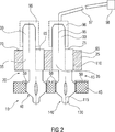
2 eine schematische Schnittansicht durch die in 1 gezeigte Kontaktanordnung eingesteckt in eine Leiterplatte. 2 a schematic sectional view through the in 1 shown contact assembly inserted into a circuit board.

1 zeigt eine schematische Schnittansicht einer Kontaktanordnung 10 mit zwei Kontaktelementen 15, 20. 2 zeigt eine schematische Schnittansicht der in 1 gezeigten Kontaktanordnung 10 eingesteckt in eine Leiterplatte 21. Dabei ist ein erstes Kontaktelement 15 rechtsseitig in 1 neben einem zweiten Kontaktelement 20 in einer Trägerplatte 25 angeordnet und von der Trägerplatte 25 insbesondere gehalten. Die Kontaktelemente 15, 20 sind baugleich. Z. B. sind sie identisch zueinander ausgebildet. Sie werden daher im Folgenden gemeinsam erläutert. 1 shows a schematic sectional view of a contact arrangement 10 with two contact elements 15 . 20 , 2 shows a schematic sectional view of the in 1 shown contact arrangement 10 plugged into a circuit board 21 , Here is a first contact element 15 right side in 1 in addition to a second contact element 20 in a carrier plate 25 arranged and from the carrier plate 25 held in particular. The contact elements 15 . 20 are identical. For example, they are identical to each other. They are therefore explained together below.

Das Kontaktelement 15, 20 umfasst einen an einem ersten Längsende 26 des Kontaktelements 15, 20 angeordneten Kontaktabschnitt 30 und einen in 1 unterhalb des Kontaktabschnitts 30 angeordneten Mittelabschnitt 35, der mit dem Kontaktabschnitt 30 verbunden ist. Unterhalb des Mittelabschnitts 35 ist an einem dem ersten Längsende 26 gegenüberliegenden zweiten Längsende 36 des Kontaktelements 15, 20 ein Einpressabschnitt 40 vorgesehen, der ausgelegt ist, in die Leiterplatte 21 mit einer Leiterbahnstruktur 50 entlang einer Einpressrichtung 55, die in 1 schematisch mittels eines Pfeils 55 dargestellt ist, eingepresst zu werden. Das Kontaktelement 15, 20 umfasst ferner eine Gesamtlängsachse 60, die parallel zu der Einpressrichtung 55 ausgerichtet ist. An dem Mittelabschnitt 35 ist des Weiteren seitlich ein Schulterabschnitt 65 vorgesehen, der in 1 strichliert dargestellt und rechtsseitig am Mittelabschnitt 35 ausgebildet ist. Der Schulterabschnitt 65 erstreckt sich lateral von dem Mittelabschnitt 35 quer zur Gesamtlängsachse 60 weg. The contact element 15 . 20 includes one at a first longitudinal end 26 of the contact element 15 . 20 arranged contact portion 30 and one in 1 below the contact section 30 arranged middle section 35 that with the contact section 30 connected is. Below the middle section 35 is at one of the first longitudinal ends 26 opposite second longitudinal end 36 of the contact element 15 . 20 a press-fit section 40 provided, which is designed in the circuit board 21 with a conductor track structure 50 along a press-in direction 55 , in the 1 schematically by means of an arrow 55 is shown to be pressed. The contact element 15 . 20 further comprises a total longitudinal axis 60 parallel to the pressfit direction 55 is aligned. At the middle section 35 is further laterally a shoulder portion 65 provided in 1 shown dashed and right side at the middle section 35 is trained. The shoulder section 65 extends laterally from the central portion 35 transverse to the overall longitudinal axis 60 path.

Unter einem Schulterabschnitt 65 wird im vorliegenden Zusammenhang insbesondere ein Abschnitt verstanden, der quer zur Gesamtlängsachse 60 um wenigstens 0,2 mm, vorzugsweise wenigstens 0,5 mm seitlich (quer zur Gesamtlängsachse 60) gegenüber dem Kontaktabschnitt 30 hervorragt. Mittels des Schulterabschnitts 65 ist am Übergang vom Mittelabschnitt 35 zum Kontaktabschnitt 30 eine Stufe in einer Seitenfläche des Kontaktelements 15, 20 ausgebildet. An der dem Kontaktabschnitt 30 zugewandten Seite des Schulterabschnitts 65 ist eine Anlagefläche 75 an dem Schulterabschnitt 65 vorgesehen. Under a shoulder section 65 is understood in the present context, in particular a section transverse to the overall longitudinal axis 60 by at least 0.2 mm, preferably at least 0.5 mm laterally (transverse to the overall longitudinal axis 60 ) opposite the contact section 30 protrudes. By means of the shoulder section 65 is at the transition from the middle section 35 to the contact section 30 a step in a side surface of the contact element 15 . 20 educated. At the contact section 30 facing side of the shoulder portion 65 is a contact surface 75 at the shoulder portion 65 intended.

Es ist auch denkbar, dass der Schulterabschnitt 65 linksseitig am Mittelabschnitt 35 angeordnet oder schräg zur Gesamtlängsachse 60 ausgerichtet ist. Zweckmäßigerweise weist das Kontaktelement 15, 12 genau einen Schulterabschnitt 65 auf und ist somit asymmetrisch bezüglich der Gesamtlängsachse 60. It is also conceivable that the shoulder section 65 left side at the middle section 35 arranged or oblique to the total longitudinal axis 60 is aligned. Conveniently, the contact element 15 . 12 exactly one shoulder section 65 on and is thus asymmetric with respect to the overall longitudinal axis 60 ,

Zur Herzstellung der Kontaktanordung 10 werden die Kontaktelemente 15, 20 an dem Trägerkörper 25 montiert. Dazu werden sie entgegen der Einpressrichtung 55 des Kontaktelements 15, 20 (in 1 von unten nach oben) in den Trägerkörper 25 eingepresst, bis im Wesentlichen der Mittelabschnitt 35 und der Schulterabschnitt 65 vollständig vom Trägerkörper 25 umgriffen werden. Dazu ist der Trägerkörper 25 aus einem Kunststoff ausgebildet. Es sind jedoch auch andere elektrisch isolierende Werkstoffe denkbar. To the heart position of Kontaktanordung 10 become the contact elements 15 . 20 on the carrier body 25 assembled. For this they are contrary to the pressing direction 55 of the contact element 15 . 20 (in 1 from bottom to top) in the carrier body 25 pressed until essentially the middle section 35 and the shoulder section 65 completely from the carrier body 25 be seized. This is the carrier body 25 made of a plastic. However, other electrically insulating materials are conceivable.

Das Kontaktelement 15, 20 wird derart in den Trägerkörper 25 eingepresst, dass die Anlagefläche 75 in Richtung der Gesamtlängsachse 60 oberhalb zu einer Oberseite 70 des Trägerkörpers 25 angeordnet ist. Die Oberseite 70 ist dabei dem Kontaktabschnitt 30 des Kontaktelements 15, 20 zugewandt. Sollte dies für spezielle Ausgestaltungen wünschenswert sein ist auch denkbar, dass die Oberseite 70 und die Anlagefläche 75 bündig abschließen oder dass die Anlagefläche 75 unterhalb der Oberseite 70 angeordnet ist. The contact element 15 . 20 is so in the carrier body 25 pressed in that the contact surface 75 in the direction of the overall longitudinal axis 60 above to a top 70 of the carrier body 25 is arranged. The top 70 is the contact section 30 of the contact element 15 . 20 facing. Should this be desirable for specific embodiments is also conceivable that the top 70 and the contact surface 75 finish flush or that the contact surface 75 below the top 70 is arranged.

Zur Montage der Kontaktanordnung an der Leiterplatte 21 ist ein Presswerkzeug 80 vorgesehen um die Kontaktanordnung 10 und deren Kontaktelemente 15, 20 in die Leiterplatte 21 einzupressen. Das Presswerkzeug 80 hat ein oberhalb des Trägerkörpers 25 angeordnetes oberes Presswerkzeugteil 81 und ein unterhalb der Leiterplatte 21 angeordnetes unteres Presswerkzeugteil 82. For mounting the contact arrangement on the circuit board 21 is a pressing tool 80 provided around the contact arrangement 10 and their contact elements 15 . 20 in the circuit board 21 to press. The pressing tool 80 has one above the carrier body 25 arranged upper pressing tool part 81 and one below the circuit board 21 arranged lower pressing tool part 82 ,

Der Kontaktabschnitt 30 wird umfangsseitig durch das obere Presswerkzeugteil 81 umgriffen, wobei das obere Presswerkzeugteil 81 einen Stempelabschnitt 85 mit einer stirnseitigen Pressfläche 90 umfasst. Die Pressfläche 90 ist dabei der Anlagefläche 75 des Schulterabschnitts 65 zugewandt. Dabei weist der Stempelabschnitt 85 eine axiale Erstreckung in Richtung der Gesamtlängsachse 60 auf, die größer ist als die axiale Erstreckung des Kontaktabschnitts 30. Die kürzere Ausgestaltung des Kontaktabschnitts 30 gegenüber der axialen Erstreckung des Stempelabschnitts 85 bewirkt, dass das Presswerkzeug 80 beim Einpressen der Kontaktanordnung 10 in die Leiterplatte 21 ausschließlich auf der Anlagefläche 75 des Schulterabschnitts 75 aufliegt und der Kontaktabschnitt 30 somit nicht verformt wird. The contact section 30 becomes circumferentially through the upper die part 81 encompassed, wherein the upper die part 81 a stamp section 85 with a frontal pressing surface 90 includes. The pressing surface 90 is the contact surface 75 of the shoulder section 65 facing. In this case, the stamp section 85 an axial extension in the direction of the overall longitudinal axis 60 which is larger than the axial extent of the contact portion 30 , The shorter design of the contact section 30 opposite the axial extent of the stamp portion 85 causes the crimping tool 80 when pressing in the contact arrangement 10 in the circuit board 21 exclusively on the contact surface 75 of the shoulder section 75 rests and the contact section 30 thus not deformed.

Das Presswerkzeug 80 ist dabei ausgelegt, eine Einpresskraft FP über den Stempelabschnitt 85 bzw. die Pressfläche 90 in die Anlagefläche 75 des Schulterabschnitts 65 einzuleiten. Der Schulterabschnitt 65 ist ausgelegt, eine zur Einpresskraft FP korrespondierende notwendige Anlagefläche 75 bereitzustellen und die in den Schulterabschnitt 65 eingeleitete Einpresskraft FP in den Einpressabschnitt 40 weiterzuleiten. Um die Einpresskraft FP abzustützen und eine Durchbiegung der Leiterplatte 21 sowie eine mögliche Beschädigung dieser beim Einpressvorgang zu vermeiden, stellt das untere Presswerkzeigteil 82 eine Einpressgegenkraft FG bereit, die der Einpresskraft FP im Wesentlichen entspricht. The pressing tool 80 is designed, a press-in force F P on the stamp section 85 or the pressing surface 90 in the contact area 75 of the shoulder section 65 initiate. The shoulder section 65 is designed, a corresponding to the pressing force F P necessary contact surface 75 provide and in the shoulder section 65 initiated pressing force F P in the press-fit 40 forward. To support the pressing force F P and a deflection of the circuit board 21 as well as to avoid possible damage during the press-in process, represents the lower press tool display part 82 a press-fit counterforce F G that substantially corresponds to the press-fit force F P.

Durch die oben erläutere Beabstandung der Anlagefläche 75 zu der Oberseite 70 des Trägerkörpers 25 wird ferner vermieden, dass das Presswerkzeug 80 auf dem Trägerkörper 25 aufsitzt und so möglicherweise das Kontaktelement 15, 20 beim Einpressen in die Leiterplatte 21 aus dem Trägerkörper 25 entgegengesetzt zur Einpressrichtung 55 herausdrückt oder der Trägerkörper 25 durch das Presswerkzeug 80 beschädigt wird. By the above-explained spacing of the contact surface 75 to the top 70 of the carrier body 25 Furthermore, it is avoided that the pressing tool 80 on the carrier body 25 is seated and so possibly the contact element 15 . 20 when pressed into the circuit board 21 from the carrier body 25 opposite to the press-in direction 55 or the carrier body 25 through the pressing tool 80 is damaged.

Der Kontaktabschnitt 30 umfasst eine erste Längsachse 95, die versetzt parallel zu der Gesamtlängsachse 60 des Kontaktelements 15, 20 angeordnet ist. Die erste Längsachse 95 verläuft in Richtung der Einpressrichtung 55 des Kontaktelements 15, 20 und ist mittig bezogen auf eine Erstreckung quer zur Gesamtlängsachse 60 im Kontaktabschnitt 30 angeordnet. Zum erleichterten Aufstecken eines Buchsenkontakts 96 auf den Kontaktabschnitt 30 weist das dem Einpresswerkzeug 80 zugewandte Ende – das ist das vom Einpressabschnitt 35 abgewandte Ende – des Kontaktabschnitts 30 eine Abschrägung 100 auf. Der Buchsenkontakt 96 kann dabei eine elektrische Verbindung 97 zu weiteren, mittels der Kontaktanordnung 10 elektrisch zu verbindenden Komponenten 98 bereitstellen. The contact section 30 includes a first longitudinal axis 95 that offset parallel to the overall longitudinal axis 60 of the contact element 15 . 20 is arranged. The first longitudinal axis 95 runs in the direction of the press-in direction 55 of the contact element 15 . 20 and is centered on an extension transverse to the overall longitudinal axis 60 in the contact section 30 arranged. For easier insertion of a socket contact 96 on the contact section 30 has that the press tool 80 facing end - that's the press-in section 35 opposite end - the contact section 30 a bevel 100 on. The socket contact 96 can be an electrical connection 97 to further, by means of the contact arrangement 10 electrically connected components 98 provide.

Ferner umfasst der Kontaktabschnitt 30 sowie der Mittelabschnitt 35 eine erste Seitenfläche 105, die bezogen auf die Gesamtlängsachse 60 auf der gegenüberliegenden Seite zum Schulterabschnitt 65 des Kontaktabschnitts 30 angeordnet ist. Die erste Seitenfläche 105 verläuft dabei parallel zur Gesamtlängsachse 60 bzw. zu der ersten Längsachse 95 und erstreckt sich durchgehend über den Kontaktabschnitt 30 und den Mittelabschnitt 35 in einer Ebene, die senkrecht zur Zeichenebene angeordnet ist. Grundsätzlich ist denkbar, dass die Seitenfläche 105 auch Knicke, Stufen oder dergleichen aufweisen kann. Wesentlich ist dabei, dass an der ersten Seitenfläche 105 keine Strukturen vorgesehen sind, die ausgelegt sind, durch das Presswerkzeug 80 betätigt zu werden, um die Einpresskraft FP in den Einpressabschnitt 40 einzuleiten. Furthermore, the contact section comprises 30 as well as the middle section 35 a first side surface 105 related to the total longitudinal axis 60 on the opposite side to the shoulder section 65 of the contact section 30 is arranged. The first side surface 105 runs parallel to the total longitudinal axis 60 or to the first longitudinal axis 95 and extends continuously over the contact portion 30 and the middle section 35 in a plane that is perpendicular to the plane of the drawing. Basically, it is conceivable that the side surface 105 also kinks, steps or the like may have. It is essential that on the first side surface 105 no structures are provided which are designed by the pressing tool 80 to be actuated to the pressing force F P in the press-fit 40 initiate.

Gegenüberliegend zur ersten Seitenfläche 105 ist ferner eine zweite Seitenfläche 110 am Schulterabschnitt 65 vorgesehen, die parallel zu der ersten Seitenfläche 105 ausgerichtet ist. Opposite to the first side surface 105 is also a second side surface 110 at the shoulder section 65 provided parallel to the first side surface 105 is aligned.

Der Einpressabschnitt 40 umfasst eine zweite Längsachse 115, die sowohl versetzt zur Gesamtlängsachse 60 als auch zur ersten Längsachse 95 des Kontaktabschnitts 30 angeordnet ist. Die zweite Längsachse 115 verläuft in Richtung der Einpressrichtung des Kontaktelements 15, 20 und ist mittig bezogen auf eine Erstreckung quer zur Gesamtlängsachse 60 im Einpressabschnitt 40 angeordnet. Ferner ist eine Ausnehmung 120 im Einpressabschnitt 40 vorgesehen, die sich längs der zweiten Längsachse 115 erstreckt. The press-fit section 40 includes a second longitudinal axis 115 that offset both the total longitudinal axis 60 as well as the first longitudinal axis 95 of the contact section 30 is arranged. The second longitudinal axis 115 runs in the direction of the press-in direction of the contact element 15 . 20 and is centered on an extension transverse to the overall longitudinal axis 60 in the press-fit section 40 arranged. Further, a recess 120 in the press-fit section 40 provided, extending along the second longitudinal axis 115 extends.

Der Einpressabschnitt 40 weist des Weiteren einen Steg 121 auf, an den sich unterseitig ein Einpresselement 125 anschließt. Der Steg 121 ist dabei in Längsrichtung zwischen dem Mittelabschnitt 30 sowie dem Schulterabschnitt 65 auf der einen Seite und dem Einpresselement 125 auf der anderen Seite angeordnet. Der Steg 121 ist quer zur Gesamtlängsachse 60 schlanker ausgebildet als der Mittelabschnitt 30 mit dem Schulterabschnitt 65. Insbesondere weist der Steg 121 eine dritte Seitenfläche 135 auf, die auf der der zweiten Seitenfläche 110 zugewandten Seite des Stegs 121 angeordnet ist. Die dritte Seitenfläche 135 verläuft parallel zu der zweiten Längsachse 115. Die dritte Seitenfläche 135 ist quer zur Gesamtlängsachse 60 beabstandet zur zweiten Seitenfläche 110 angeordnet. So kann ein (in den Figuren nicht dargestelltes) Werkzeug im Bereich des Stegs 121 angeordnet werden um das Kontaktelement 15, 20 zur Montage der Kontaktanordnung 10 in den Trägerkörper 25 einzuschieben, wie weiter vorne bereits beschrieben. The press-fit section 40 also has a footbridge 121 on, on the underside of a press-in element 125 followed. The jetty 121 is in the longitudinal direction between the middle section 30 as well as the shoulder section 65 on the one hand and the press-in element 125 arranged on the other side. The jetty 121 is transverse to the overall longitudinal axis 60 slimmer than the middle section 30 with the shoulder section 65 , In particular, the bridge points 121 a third side surface 135 on that on the second side surface 110 facing side of the bridge 121 is arranged. The third side surface 135 runs parallel to the second longitudinal axis 115 , The third side surface 135 is transverse to the overall longitudinal axis 60 spaced from the second side surface 110 arranged. Thus, a tool (not shown in the figures) in the region of the web 121 be arranged around the contact element 15 . 20 for mounting the contact arrangement 10 in the carrier body 25 push in, as described earlier.

Die erste Längsachse 95 und die zweite Längsachse 115, sind in entgegengesetzter Richtung gegenüber der Gesamtlängsachse versetzt. Auf diese Weise ist der Steg 121 zumindest teilweise in Richtung der ersten und zweiten Längsachse 95, 115 der Anlagefläche 75 unterhalb angeordnet ist, d.h. er überlappt in Draufsicht entlang der Längsachsen 60, 95, 115 zumindest teilweise mit der Anlagefläche 75. Mit Vorteil kann so die über die Anlagefläche 75 eingebrachte Einpresskraft FP im Wesentlichen parallel zur Gesamtlängsachse 60 in den Steg 121 eingeleitet werden. Die Gefahr eines Verkippens des Kontaktelements 15, 20 beim Einpressen in die Leiterplatte 21 ist besonders gering. Ferner kann dadurch eine Erstreckung des Kontaktelements 15, 20 quer zur ersten und/oder zweiten Längsachse 95, 115 minimiert werden. The first longitudinal axis 95 and the second longitudinal axis 115 , are offset in the opposite direction to the total longitudinal axis. That way, the bridge is 121 at least partially in the direction of the first and second longitudinal axis 95 . 115 the contact surface 75 is arranged below, ie it overlaps in plan view along the longitudinal axes 60 . 95 . 115 at least partially with the contact surface 75 , With advantage can so over the contact surface 75 introduced pressing force F P substantially parallel to the total longitudinal axis 60 in the footbridge 121 be initiated. The risk of tilting of the contact element 15 . 20 when pressed into the circuit board 21 is particularly low. Furthermore, this can be an extension of the contact element 15 . 20 transverse to the first and / or second longitudinal axis 95 . 115 be minimized.

Ferner verjüngt sich das Einpresselement 125 sowohl von den Kontaktflächen 126 in Richtung der Leiterplatte 21 hin als auch zu einer am unteren Ende des Kontaktelements 15, 20 angeordneten Einpressspitze 130. Das Einpresselement 125 umfasst seitlich parallel zur zweiten Längsachse 115 angeordnet Kontaktflächen 126. Die Ausnehmung 120 ermöglicht das elastische Verformen des Einpresselements 125, so dass die Kontaktflächen 126 zuverlässig an die Leiterplattenstruktur 50 angepresst werden. Ferner wird durch die Ausgestaltung der Ausnehmung 120 die Einpresskraft FP reduziert. Selbstverständlich kann die Ausnehmung 120 andersartig als in den 1 und 2 gezeigt sein oder es kann auf die Ausnehmung 120 verzichtet werden. Die Kontaktflächen 126 liegen in eingepresstem Zustand (vgl. 2) an der Leiterplattenstruktur 50 der Leiterplatte 21 an und stellen einen elektrischen Kontakt zwischen dem Kontaktelement 15, 20 und der Leiterplattenstruktur 50 bereit. Durch die elektrisch leitende Ausgestaltung des Kontaktelements 15, 20 kann somit die Leiterplattenstruktur 21 über den Buchsenkontakt 96 mit den weiteren elektrischen Komponenten verbunden werden. Furthermore, the press-in element tapers 125 both from the contact surfaces 126 in the direction of the circuit board 21 towards and at one of the lower end of the contact element 15 . 20 arranged Einpressspitze 130 , The press-fit element 125 includes laterally parallel to the second longitudinal axis 115 arranged contact surfaces 126 , The recess 120 allows the elastic deformation of the press-in element 125 so that the contact surfaces 126 Reliable to the PCB structure 50 be pressed. Furthermore, by the configuration of the recess 120 the pressing force F P reduced. Of course, the recess 120 different than in the 1 and 2 be shown or it may be on the recess 120 be waived. The contact surfaces 126 lie in pressed state (see. 2 ) on the circuit board structure 50 the circuit board 21 and make an electrical contact between the contact element 15 . 20 and the circuit board structure 50 ready. Due to the electrically conductive design of the contact element 15 . 20 can thus the circuit board structure 21 over the socket contact 96 be connected to the other electrical components.

Durch die identische Ausbildung der beiden Kontaktelemente 15, 20 mit ausschließlich einem Schulterabschnitt 65 kann eine besonders kompakte Anordnung des ersten Kontaktelements 15 zu dem zweiten Kontaktelement 20 dadurch erfolgen, dass die zweite Seitenfläche 110 des zweiten Kontaktelements 20 der ersten Seitenfläche 105 des ersten Kontaktelements 15 zugewandt ist, wobei beide Kontaktelemente 15, 20 in einer Ebene im Trägerkörper 25 angeordnet sind. Dadurch wird der Platzbedarf zur Anordnung von zwei Kontaktelementen 15, 20 in Richtung quer zur Einpressrichtung 55 gegenüber bekannten Kontaktelementen derart reduziert, dass die Anzahl der Kontaktelemente 15, 20 in dem Trägerkörper 25 erhöht werden kann. Due to the identical design of the two contact elements 15 . 20 with only one shoulder section 65 may be a particularly compact arrangement of the first contact element 15 to the second contact element 20 be done by the second side surface 110 of the second contact element 20 the first side surface 105 of the first contact element 15 facing, wherein both contact elements 15 . 20 in a plane in the carrier body 25 are arranged. As a result, the space required for the arrangement of two contact elements 15 . 20 in the direction transverse to the press-in direction 55 reduced compared to known contact elements such that the number of contact elements 15 . 20 in the carrier body 25 can be increased.

Ferner kann durch die oben beschriebene Ausgestaltung beim Stanzen der Kontaktelemente 15, 20 aus einem Flachmaterial, insbesondere aus einem kupferhaltigen Kontaktwerkstoff, insbesondere aus einem Kupfer-Zinn-Bronze- oder aus einem Kupfer-Nickel-Silizium-Werkstoff, das benötigte Flachmaterial reduziert werden, so dass das Kontaktelement 15, 20 und die Kontaktanordnung 10 mit den Kontaktelementen 15, 20 kostengünstiger und gegebenenfalls leichter als bekannte Anordnungen mit Kontaktelementen ist. Furthermore, by the above-described embodiment when punching the contact elements 15 . 20 from a flat material, in particular from a copper-containing contact material, in particular from a copper-tin-bronze or from a copper-nickel-silicon material, the required flat material can be reduced, so that the contact element 15 . 20 and the contact arrangement 10 with the contact elements 15 . 20 cheaper and possibly lighter than known arrangements with contact elements.

Die Erfindung ist nicht durch die Beschreibung anhand der Ausführungsbeispiele auf diese beschränkt. Vielmehr umfasst die Erfindung jedes neue Merkmal sowie jede Kombination von Merkmalen, was insbesondere jede Kombination von Merkmalen in den Ausführungsbeispielen und Patentansprüchen beinhaltet. Variationen können vom Fachmann hieraus abgeleitet werden, ohne den Schutzumfang der Erfindung zu verlassen. The invention is not limited by the description based on the embodiments of these. Rather, the invention includes every new feature and every combination of features, which in particular includes any combination of features in the embodiments and claims. Variations may be deduced therefrom by those skilled in the art without departing from the scope of the invention.

So kann beispielsweise bei einer ersten Variante an der ersten und/oder zweiten Seitenfläche 105, 110 ein Verankerungsabschnitt 140 vorgesehen sein, der beispielhaft in 1 am zweiten Kontaktelement 20 schematisch gezeigt ist und der eine tannenbaumartige Kontur aufweist, die ausgelegt ist, die Fläche der Seitenfläche 105, 110 zu vergrößern. Mittels des Verankerungsabschnitts 140 kann der Trägerkörper 25 zuverlässig mit dem Kontaktelement 15, 20 verbunden werden, so dass während des Einpressens der Kontaktanordnung 10 in die Leiterplatte 21 durch das Presswerkzeug 80 das Herausdrücken des Kontaktelements 15, 20 aus dem Trägerkörper 25 vermieden wird. Es bieten sich selbstverständlich statt der gezeigten tannenbaumartigen Kontur auch andere Konturen an, wie etwa eine rechteckförmige oder verrundete Kontur. Die Kontur kann auch eine sägezahnförmige Kontur sein. Wesentlich dabei ist, dass diese nicht zur Anlage des Pressstempels 85 geeignet sind, so dass ein schmales Kontaktelement 15, 20 bereitgestellt wird. Auch kann zusätzlich oder alternativ der Verankerungsabschnitt 140 an dem Schulterabschnitt 65 angeordnet sein. For example, in a first variant on the first and / or second side surface 105 . 110 an anchoring section 140 be provided, the exemplary in 1 on the second contact element 20 is shown schematically and having a fir-tree-like contour, which is designed, the surface of the side surface 105 . 110 to enlarge. By means of the anchoring section 140 can the carrier body 25 reliable with the contact element 15 . 20 be connected so that during the pressing of the contact assembly 10 in the circuit board 21 through the pressing tool 80 the pressing out of the contact element 15 . 20 from the carrier body 25 is avoided. Of course, instead of the fir-tree-like contour shown, other contours are also available, such as a rectangular or rounded contour. The contour can also be a sawtooth-shaped contour. It is essential that these are not for the installation of the press ram 85 are suitable, so that a narrow contact element 15 . 20 provided. Also can additionally or alternatively, the anchoring section 140 at the shoulder portion 65 be arranged.

Auch kann der Steg 121 des Einpressabschnitts 40 nur an dem Schulterabschnitt 65 angeordnet sein anstatt lateral auch mit einem Teil des Mittelabschnitts 35 zu überlappen. Ferner ist die in den Figuren gezeigte Ausgestaltung des Kontaktabschnitts 30 und/oder des Einpressabschnitts 40 beispielhaft. Je nach zu übertragenden elektrischen Spannungen und/oder Strömen zwischen dem Kontaktabschnitt 30 und dem Einpressabschnitt 40 können der Kontaktabschnitt 30 und/oder der Einpressabschnitt 40 in ihrer Ausgestaltung an die elektrische Spannungen und/oder Ströme angepasst werden. Im Rahmen dessen können beispielsweise die Kontaktflächen 126 alternativ auch schräg zur zweiten Längsachse 115 angeordnet sein. Also, the bridge can 121 of the press-in section 40 only at the shoulder section 65 be arranged instead also laterally with a part of the central portion 35 to overlap. Furthermore, the embodiment of the contact section shown in the figures is 30 and / or the press-in section 40 exemplary. Depending on the electrical voltages and / or currents to be transmitted between the contact section 30 and the press-in section 40 can the contact section 30 and / or the press-in section 40 be adapted in their embodiment to the electrical voltages and / or currents. As part of this, for example, the contact surfaces 126 alternatively also obliquely to the second longitudinal axis 115 be arranged.

Ferner ist das Kontaktelement 15, 20 in der gezeigten Ausführungsform aus einem Flachbandmaterial gefertigt und somit flach in der Zeichenebene ausgebildet. Mit anderen Worten wird eine Haupterstreckungsebene des Kontaktelements 15, 20 durch die Gesamtlängsache 60 und den von der ersten Längsachse 95 zur zweiten Längsachse 115 gerichteten Abstandsvektor aufgespannt. Die räumliche Ausdehnung des Kontaktelements 15, 20 ist in der Haupterstreckungsebene vorzugsweise mindestens fünf mal so groß wie senkrecht dazu. Bei alternativen Varianten kann das Kontaktelement 15, 20 abschnittsweise eine zylindrische oder elliptische Grundform aufweisen. Furthermore, the contact element 15 . 20 made in the embodiment shown from a flat strip material and thus formed flat in the plane of the drawing. In other words, a main extension plane of the contact element 15 . 20 by the overall length 60 and from the first longitudinal axis 95 to the second longitudinal axis 115 directed distance vector spanned. The spatial extent of the contact element 15 . 20 is preferably at least five times as large in the main plane of extension as perpendicular thereto. In alternative variants, the contact element 15 . 20 sections have a cylindrical or elliptical basic shape.

Im Aufsührungsbeispiel der 1 und 2 ist die Anlagefläche 75 bzw. die korrespondierend zur Anlagefläche 75 ausgerichtete Einpressfläche 90 senkrecht zur Gesamtlängsachse 60 angeordnet. Es ist auch denkbar, dass die Einpressfläche 90 des Stempelabschnitts 85 bzw. die Anlagefläche 75 des Schulterabschnitts 65 schräg zur Gesamtlängsachse 60 angeordnet sind. Beispielsweise kann die Anlagefläche 75, im lateralen Verlauf zum Kontaktabschnitt 30 hin, axial in Richtung zu dem Einpressabschnitt 40 hin verlaufen. Die Anlagefläche 75 schließt dann insbesondere mit der angrenzenden Seitenfläche des Kontaktabschnitts 65 einen spitzen Winkel ein. Auf diese Weise ist mittels der mechanischen Wechselwirkung des Einpresswerkzeugs 80 mit dem Kontaktelement 15, 20 – insbesondere mit der Anlagefläche 75 und mit der angrenzenden Seitenfläche des Kontaktabschnitts 65 – eine besonders gute Drehmoment-Kompensation erzielbar. In the example of the 1 and 2 is the contact surface 75 or the corresponding to the contact surface 75 aligned pressing surface 90 perpendicular to the overall longitudinal axis 60 arranged. It is also conceivable that the press-fit surface 90 of the stamp section 85 or the contact surface 75 of the shoulder section 65 oblique to the total longitudinal axis 60 are arranged. For example, the contact surface 75 , in the lateral course to the contact section 30 towards, axially toward the press-in section 40 run out. The contact surface 75 then closes in particular with the adjacent side surface of the contact section 65 an acute angle. In this way, by means of the mechanical interaction of the press-fit tool 80 with the contact element 15 . 20 - In particular with the contact surface 75 and with the adjacent side surface of the contact portion 65 - A particularly good torque compensation can be achieved.

ZITATE ENTHALTEN IN DER BESCHREIBUNG QUOTES INCLUDE IN THE DESCRIPTION

Diese Liste der vom Anmelder aufgeführten Dokumente wurde automatisiert erzeugt und ist ausschließlich zur besseren Information des Lesers aufgenommen. Die Liste ist nicht Bestandteil der deutschen Patent- bzw. Gebrauchsmusteranmeldung. Das DPMA übernimmt keinerlei Haftung für etwaige Fehler oder Auslassungen.This list of the documents listed by the applicant has been generated automatically and is included solely for the better information of the reader. The list is not part of the German patent or utility model application. The DPMA assumes no liability for any errors or omissions.

Zitierte PatentliteraturCited patent literature

  • DE 10228450 A1 [0002] DE 10228450 A1 [0002]

Claims (13)

Kontaktelement (15, 20) aufweisend: – einen an einem ersten Längsende (26) angeordneten Einpressabschnitt (40), der ausgelegt ist, in die Leiterplatte (21) eingepresst zu werden, – einen Kontaktabschnitt (30), der an einem dem ersten Längsende (26) gegenüberliegenden zweiten Längsende (36) des Kontaktelements (15, 20) angeordnet ist, und – genau einen Schulterabschnitt (65), der zwischen dem Kontaktabschnitt (30) und dem Einpressabschnitt (40) angeordnet ist, seitlich gegenüber dem Kontaktabschnitt (40) hervorragt, und der ausgelegt ist, eine Einpresskraft (FP) in den Einpressabschnitt (40) einzuleiten. Contact element ( 15 . 20 ) comprising: - one at a first longitudinal end ( 26 ) arranged press-in section ( 40 ), which is designed in the printed circuit board ( 21 ), - a contact section ( 30 ) located at a first longitudinal end ( 26 ) opposite second longitudinal end ( 36 ) of the contact element ( 15 . 20 ), and - exactly one shoulder section ( 65 ) located between the contact section ( 30 ) and the press-in section ( 40 ) is arranged, laterally opposite the contact portion ( 40 protruding, and which is designed, a press-in force (F P ) in the press-in section ( 40 ). Kontaktelement (15, 20) nach Anspruch 1, dadurch gekennzeichnet, dass – der Kontaktabschnitt (30) eine erste Längsachse (95) aufweist, – der Einpressabschnitt (40) eine zweite Längsachse (115) aufweist, und – der Kontaktabschnitt (30) derart gegenüber dem Einpressabschnitt (40) angeordnet ist, dass die erste Längsachse (95) versetzt zu der zweiten Längsachse (115) angeordnet ist. Contact element ( 15 . 20 ) according to claim 1, characterized in that - the contact section ( 30 ) a first longitudinal axis ( 95 ), - the press-in section ( 40 ) a second longitudinal axis ( 115 ), and - the contact section ( 30 ) in such a way opposite the press-in section ( 40 ) is arranged such that the first longitudinal axis ( 95 ) offset to the second longitudinal axis ( 115 ) is arranged. Kontaktelement (15, 20) nach Anspruch 2, wobei – der Kontaktabschnitt (30) spiegelsymmetrisch zur ersten Längsachse (95) ausgebildet ist, – der Einpressabschnitt (40) spiegelsymmetrisch zur zweiten Längsachse (115) ausgebildet ist, und – das Kontaktelement (15, 20) bezüglich einer Gesamtlängsachse (60) asymmetrisch ausgebildet ist. Contact element ( 15 . 20 ) according to claim 2, wherein - the contact section ( 30 ) mirror-symmetrical to the first longitudinal axis ( 95 ), - the press-in section ( 40 ) mirror-symmetrical to the second longitudinal axis ( 115 ), and - the contact element ( 15 . 20 ) with respect to a total longitudinal axis ( 60 ) is asymmetrical. Kontaktelement (15, 20) nach einem der vorhergehenden Ansprüche mit einem Mittelabschnitt (35), der in Längsrichtung zwischen dem Kontaktabschnitt (30) und dem Einpressabschnitt (40) angeordnet ist und den Schulterabschnitt (65) enthält, dadurch gekennzeichnet, dass eine erste Seitenfläche (105) gegenüberliegend zum Schulterabschnitt (65) seitlich am Mittelabschnitt (35) und am Kontaktabschnitt (30) vorgesehen ist, wobei die erste Seitenfläche (105) sich zumindest teilweise durchgehend über den Kontaktabschnitt (30) und zumindest teilweise über den Mittelabschnitt (35) erstreckt. Contact element ( 15 . 20 ) according to one of the preceding claims, having a middle section ( 35 ) longitudinally between the contact portion ( 30 ) and the press-in section ( 40 ) is arranged and the shoulder portion ( 65 ), characterized in that a first side surface ( 105 ) opposite the shoulder portion ( 65 ) laterally at the middle section ( 35 ) and at the contact section ( 30 ), wherein the first side surface ( 105 ) at least partially through the contact section ( 30 ) and at least partially over the middle section ( 35 ). Kontaktelement (15, 20) nach Anspruch 4 unter Rückbezug auf einen der Ansprüche 2 oder 3, dadurch gekennzeichnet, dass sich die erste Seitenfläche (105) über den Kontaktabschnitt (30) und den Mittelabschnitt (35) in einer Ebene erstreckt, die parallel zu der ersten und/oder der zweiten Längsachse (95) ausgerichtet ist. Contact element ( 15 . 20 ) according to claim 4 with reference to one of claims 2 or 3, characterized in that the first side surface ( 105 ) via the contact section ( 30 ) and the middle section ( 35 ) extends in a plane parallel to the first and / or the second longitudinal axis ( 95 ) is aligned. Kontaktelement (15, 20) nach einem der Ansprüche 2 bis 5, dadurch gekennzeichnet, dass der Einpressabschnitt (40) zumindest in Richtung der ersten und/oder zweiten Längsachse (95, 115) zumindest teilweise lateral mit dem Schulterabschnitt (65) überlappt. Contact element ( 15 . 20 ) according to one of claims 2 to 5, characterized in that the press-in section ( 40 ) at least in the direction of the first and / or second longitudinal axis ( 95 . 115 ) at least partially laterally with the shoulder portion ( 65 ) overlaps. Kontaktelement (15, 20) nach einem der vorhergehenden Ansprüche, dadurch gekennzeichnet, dass der Schulterabschnitt (65) eine Anlagefläche (75) umfasst, die auf einer dem Kontaktabschnitt (30) zugewandten Seite des Schulterabschnitts (65) angeordnet ist, wobei der Einpressabschnitt (40) angrenzend an den Schulterabschnitt (40) angeordnet ist und in Draufsicht entlang der zweiten Längsachse (115) zumindest teilweise mit der Anlagefläche (75) überlappt. Contact element ( 15 . 20 ) according to one of the preceding claims, characterized in that the shoulder portion ( 65 ) a contact surface ( 75 ) located on one of the contact sections ( 30 ) facing side of the shoulder portion ( 65 ) is arranged, wherein the press-in section ( 40 ) adjacent to the shoulder portion ( 40 ) is arranged and in plan view along the second longitudinal axis ( 115 ) at least partially with the contact surface ( 75 ) overlaps. Kontaktelement (15, 20) nach einem der Ansprüche 4 bis 7, dadurch gekennzeichnet, dass – an dem Schulterabschnitt (65) eine gegenüberliegend zur ersten Seitenfläche (105) angeordnete zweite Seitenfläche (110) vorgesehen ist, – der Einpressabschnitt (40) eine dritte Seitenfläche (135) umfasst, die dem Schulterabschnitt (65) zugewandt ist, und – die dritte Seitenfläche (135) in Richtung quer zur zweiten Längsachse (115) beabstandet zur zweiten Seitenfläche (110) des Schulterabschnitts (65) angeordnet ist. Contact element ( 15 . 20 ) according to one of claims 4 to 7, characterized in that - at the shoulder portion ( 65 ) one opposite the first side surface ( 105 ) arranged second side surface ( 110 ) is provided, - the press-in section ( 40 ) a third side surface ( 135 ), the shoulder portion ( 65 ), and - the third side surface ( 135 ) in the direction transverse to the second longitudinal axis ( 115 ) spaced from the second side surface ( 110 ) of the shoulder portion ( 65 ) is arranged. Kontaktelement (15, 20) nach einem der Ansprüche 1 bis 8, dadurch gekennzeichnet, dass wenigstens ein Verankerungsabschnitt (140) vorgesehen ist, der im Mittelabschnitt (35) und/oder im Schulterabschnitt (65) angeordnet ist. Contact element ( 15 . 20 ) according to one of claims 1 to 8, characterized in that at least one anchoring section ( 140 ), which is in the middle section ( 35 ) and / or in the shoulder portion ( 65 ) is arranged. Kontaktelement (15, 20) nach Anspruch 9, dadurch gekennzeichnet, dass wenigstens ein Verankerungsabschnitt (140) an der ersten und/oder zweiten Seitenfläche (105, 110) angeordnet ist. Contact element ( 15 . 20 ) according to claim 9, characterized in that at least one anchoring section ( 140 ) on the first and / or second side surface ( 105 . 110 ) is arranged. Kontaktelement (15, 20) nach einem der Ansprüche 1 bis 10, dadurch gekennzeichnet, dass das Kontaktelement (15, 20) mittels eines Stanzprozesses aus einem Flachmaterial herstellbar ist. Contact element ( 15 . 20 ) according to one of claims 1 to 10, characterized in that the contact element ( 15 . 20 ) can be produced by means of a stamping process from a flat material. Kontaktanordnung (10) mit einem ersten Kontaktelement (15, 20) gemäß einem der Ansprüche 3 bis 11, wenigstens einem zweiten Kontaktelement (15, 20) gemäß einem der vorhergehenden Ansprüche und einem Trägerkörper (25), wobei die beiden Kontaktelemente (15, 20) nebeneinander im Trägerkörper (25) angeordnet sind, und dem Schulterabschnitt (65) des zweiten Kontaktelements (20) die erste Seitenfläche (105) des ersten Kontaktelements gegenüberliegend zugewandt ist. Contact arrangement ( 10 ) with a first contact element ( 15 . 20 ) according to one of claims 3 to 11, at least one second contact element ( 15 . 20 ) according to one of the preceding claims and a carrier body ( 25 ), wherein the two contact elements ( 15 . 20 ) side by side in the carrier body ( 25 ) are arranged, and the shoulder portion ( 65 ) of the second contact element ( 20 ) the first side surface ( 105 ) of the first contact element faces opposite. Kontaktanordnung (10) nach Anspruch 12, wobei – der Trägerkörper (25) umfangsseitig das erste und das zweite Kontaktelement (15, 20) zumindest teilweise im Bereich des Mittelabschnitts (35) und des Schulterabschnitts (65) umgreift, – der Trägerkörper (25) eine in Richtung des Kontaktabschnitts (30) gewandte Oberseite (70) umfasst, – der Schulterabschnitt (65) eine dem Einpressabschnitt (40) abgewandte Anlagefläche (95) zum Anliegen eines Einpresswerkzeugs (80) aufweist, und – die Anlagefläche (95) zu der Oberseite (65) beabstandet angeordnet ist. Contact arrangement ( 10 ) according to claim 12, wherein - the carrier body ( 25 ) peripherally the first and the second contact element ( 15 . 20 ) at least partly in the area of the middle section ( 35 ) and the shoulder portion ( 65 ), - the carrier body ( 25 ) one in the direction of the contact section ( 30 ) facing top ( 70 ), - the shoulder portion ( 65 ) a the press-in section ( 40 ) facing away from contact surface ( 95 ) for abutment of a press-fit tool ( 80 ), and - the contact surface ( 95 ) to the top ( 65 ) is arranged at a distance.
DE102012218433.3A 2012-10-10 2012-10-10 Contact arrangement Active DE102012218433B4 (en)

Priority Applications (1)

Application Number Priority Date Filing Date Title
DE102012218433.3A DE102012218433B4 (en) 2012-10-10 2012-10-10 Contact arrangement

Applications Claiming Priority (1)

Application Number Priority Date Filing Date Title
DE102012218433.3A DE102012218433B4 (en) 2012-10-10 2012-10-10 Contact arrangement

Publications (2)

Publication Number Publication Date
DE102012218433A1 true DE102012218433A1 (en) 2014-04-10
DE102012218433B4 DE102012218433B4 (en) 2021-09-30

Family

ID=50337024

Family Applications (1)

Application Number Title Priority Date Filing Date
DE102012218433.3A Active DE102012218433B4 (en) 2012-10-10 2012-10-10 Contact arrangement

Country Status (1)

Country Link
DE (1) DE102012218433B4 (en)

Cited By (4)

* Cited by examiner, † Cited by third party
Publication number Priority date Publication date Assignee Title
EP3113289A1 (en) * 2015-06-30 2017-01-04 Souriau Method for mounting a press fit multi-contact connector
WO2019048290A1 (en) * 2017-09-05 2019-03-14 Robert Bosch Gmbh CONTACT ELEMENT, CONNECTOR UNIT AND CONTROLLER
CN113839237A (en) * 2020-06-24 2021-12-24 罗森伯格高频技术有限及两合公司 Electric plug connector and electric connecting device
US20220131295A1 (en) * 2020-10-27 2022-04-28 TE Connectivity Services Gmbh Terminal with offset connection section

Citations (3)

* Cited by examiner, † Cited by third party
Publication number Priority date Publication date Assignee Title
EP0706724B1 (en) * 1993-04-19 1997-01-15 Berg Electronics Manufacturing B.V. Hold-down element for electrical and/or electronic components
DE10228450A1 (en) 2002-06-26 2004-01-15 Conti Temic Microelectronic Gmbh Contact for circuit board with conductor path structure and electronic components, has press-in zone with press-in pin pressed into circuit board for forming contact point on conductor path structure
DE202007013239U1 (en) * 2007-03-14 2007-11-22 Ept Gmbh & Co. Kg PCB connector

Patent Citations (3)

* Cited by examiner, † Cited by third party
Publication number Priority date Publication date Assignee Title
EP0706724B1 (en) * 1993-04-19 1997-01-15 Berg Electronics Manufacturing B.V. Hold-down element for electrical and/or electronic components
DE10228450A1 (en) 2002-06-26 2004-01-15 Conti Temic Microelectronic Gmbh Contact for circuit board with conductor path structure and electronic components, has press-in zone with press-in pin pressed into circuit board for forming contact point on conductor path structure
DE202007013239U1 (en) * 2007-03-14 2007-11-22 Ept Gmbh & Co. Kg PCB connector

Cited By (12)

* Cited by examiner, † Cited by third party
Publication number Priority date Publication date Assignee Title
EP3113289A1 (en) * 2015-06-30 2017-01-04 Souriau Method for mounting a press fit multi-contact connector
FR3038464A1 (en) * 2015-06-30 2017-01-06 Souriau METHOD FOR MOUNTING A PRESSURE INSERTED MULTICONTACT CONNECTOR
WO2019048290A1 (en) * 2017-09-05 2019-03-14 Robert Bosch Gmbh CONTACT ELEMENT, CONNECTOR UNIT AND CONTROLLER
CN111052513A (en) * 2017-09-05 2020-04-21 罗伯特·博世有限公司 Contact elements, plug connection units and controllers
CN111052513B (en) * 2017-09-05 2021-06-15 罗伯特·博世有限公司 Contact elements, plug connection units and controllers
CN113839237A (en) * 2020-06-24 2021-12-24 罗森伯格高频技术有限及两合公司 Electric plug connector and electric connecting device
EP3930111A1 (en) * 2020-06-24 2021-12-29 Rosenberger Hochfrequenztechnik GmbH & Co. KG Electrical connector and electrical connection assembly
US11855394B2 (en) 2020-06-24 2023-12-26 Rosenberger Hochfrequenztechnik Gmbh & Co. Kg Electrical plug connector and electrical connecting arrangement
US20220131295A1 (en) * 2020-10-27 2022-04-28 TE Connectivity Services Gmbh Terminal with offset connection section
CN114498115A (en) * 2020-10-27 2022-05-13 泰连服务有限公司 Terminals with Offset Connections
US11349239B2 (en) * 2020-10-27 2022-05-31 TE Connectivity Services Gmbh Terminal with offset connection section
DE102021127563B4 (en) 2020-10-27 2024-10-24 Te Connectivity Solutions Gmbh Connection with an offset connection section and connectors with such a connection

Also Published As

Publication number Publication date
DE102012218433B4 (en) 2021-09-30

Similar Documents

Publication Publication Date Title
EP2441129B1 (en) Press-in contact for connecting an electronic component to a printed circuit board and press-in tool for producing a press-in contact
DE9017536U1 (en) Connector socket
EP1777720A1 (en) Electrical device, particularly relay socket, with spring clip and method of manufacture
DE69603318T2 (en) Device for electrical contacts with insulation displacement
DE102006012722B3 (en) Press-in contact e.g. for circuit-board pluggable connector, or bus-bar, uses overhangs pressing against one another to form flexible connection with recesses
DE69521249T2 (en) Wiring construction of an electrical junction box
EP3375048B1 (en) Plug contact
DE68923016T2 (en) Electrical tail pin with compliant part.
DE69806296T2 (en) Electrical connector
DE4111054C2 (en)
DE102005021568A1 (en) Printed circuit board with pressfit connection
EP1743402A1 (en) Pin for the soldering-free electric connection to a printed circuit board, a pressing-in tool, in addition to a method for the production of a soldering-free electric connection
DE112022005910T5 (en) Connection unit, socket connection and plug connection
EP2561582B1 (en) Electrical plug contact
DE69328387T2 (en) Printed circuit board with supporting edge connector device, method for assembling it and connector for receiving it
DE102012218433B4 (en) Contact arrangement
DE4310369A1 (en) adapter
DE102016200243A1 (en) Contact connector, terminal contact and method of making a contact connector
DE102012205969A1 (en) sensor device
DE68915487T2 (en) Contact arrangement.
DE2363597A1 (en) ELECTRIC PLUG
DE19844863C2 (en) Socket contact element and method for its production
EP0641040A2 (en) Press fit spring contact connector
DE2527318A1 (en) PLUG-IN DEVICE
DE102020209544A1 (en) Electrical connector, circuit assembly and method of forming a circuit assembly

Legal Events

Date Code Title Description
R012 Request for examination validly filed
R016 Response to examination communication
R081 Change of applicant/patentee

Owner name: VITESCO TECHNOLOGIES GMBH, DE

Free format text: FORMER OWNER: CONTINENTAL AUTOMOTIVE GMBH, 30165 HANNOVER, DE

R016 Response to examination communication
R018 Grant decision by examination section/examining division
R084 Declaration of willingness to licence
R081 Change of applicant/patentee

Owner name: SCHAEFFLER TECHNOLOGIES AG & CO. KG, DE

Free format text: FORMER OWNER: VITESCO TECHNOLOGIES GMBH, 30165 HANNOVER, DE

Owner name: VITESCO TECHNOLOGIES GMBH, DE

Free format text: FORMER OWNER: VITESCO TECHNOLOGIES GMBH, 30165 HANNOVER, DE

R020 Patent grant now final
R081 Change of applicant/patentee

Owner name: SCHAEFFLER TECHNOLOGIES AG & CO. KG, DE

Free format text: FORMER OWNER: VITESCO TECHNOLOGIES GMBH, 93055 REGENSBURG, DE