DE102012112644B4 - Spotlight for illuminating an object and distance measuring device with the spotlight - Google Patents
Spotlight for illuminating an object and distance measuring device with the spotlight Download PDFInfo
- Publication number
- DE102012112644B4 DE102012112644B4 DE102012112644.5A DE102012112644A DE102012112644B4 DE 102012112644 B4 DE102012112644 B4 DE 102012112644B4 DE 102012112644 A DE102012112644 A DE 102012112644A DE 102012112644 B4 DE102012112644 B4 DE 102012112644B4
- Authority
- DE
- Germany
- Prior art keywords
- radiation
- units
- radiation units
- measuring device
- distance measuring
- Prior art date
- Legal status (The legal status is an assumption and is not a legal conclusion. Google has not performed a legal analysis and makes no representation as to the accuracy of the status listed.)
- Expired - Fee Related
Links
Images


Classifications
-
- G—PHYSICS
- G01—MEASURING; TESTING
- G01S—RADIO DIRECTION-FINDING; RADIO NAVIGATION; DETERMINING DISTANCE OR VELOCITY BY USE OF RADIO WAVES; LOCATING OR PRESENCE-DETECTING BY USE OF THE REFLECTION OR RERADIATION OF RADIO WAVES; ANALOGOUS ARRANGEMENTS USING OTHER WAVES
- G01S7/00—Details of systems according to groups G01S13/00, G01S15/00, G01S17/00
- G01S7/48—Details of systems according to groups G01S13/00, G01S15/00, G01S17/00 of systems according to group G01S17/00
- G01S7/481—Constructional features, e.g. arrangements of optical elements
- G01S7/4814—Constructional features, e.g. arrangements of optical elements of transmitters alone
- G01S7/4815—Constructional features, e.g. arrangements of optical elements of transmitters alone using multiple transmitters
-
- G—PHYSICS
- G01—MEASURING; TESTING
- G01S—RADIO DIRECTION-FINDING; RADIO NAVIGATION; DETERMINING DISTANCE OR VELOCITY BY USE OF RADIO WAVES; LOCATING OR PRESENCE-DETECTING BY USE OF THE REFLECTION OR RERADIATION OF RADIO WAVES; ANALOGOUS ARRANGEMENTS USING OTHER WAVES
- G01S17/00—Systems using the reflection or reradiation of electromagnetic waves other than radio waves, e.g. lidar systems
- G01S17/88—Lidar systems specially adapted for specific applications
-
- G—PHYSICS
- G01—MEASURING; TESTING
- G01S—RADIO DIRECTION-FINDING; RADIO NAVIGATION; DETERMINING DISTANCE OR VELOCITY BY USE OF RADIO WAVES; LOCATING OR PRESENCE-DETECTING BY USE OF THE REFLECTION OR RERADIATION OF RADIO WAVES; ANALOGOUS ARRANGEMENTS USING OTHER WAVES
- G01S7/00—Details of systems according to groups G01S13/00, G01S15/00, G01S17/00
- G01S7/48—Details of systems according to groups G01S13/00, G01S15/00, G01S17/00 of systems according to group G01S17/00
- G01S7/483—Details of pulse systems
- G01S7/484—Transmitters
Landscapes
- Engineering & Computer Science (AREA)
- Physics & Mathematics (AREA)
- Computer Networks & Wireless Communication (AREA)
- General Physics & Mathematics (AREA)
- Radar, Positioning & Navigation (AREA)
- Remote Sensing (AREA)
- Electromagnetism (AREA)
- Measurement Of Optical Distance (AREA)
Abstract
Abstandsmessvorrichtung mit einem Strahler zum Beleuchten eines Objekts mit einer vorherbestimmten Intensität, wobei der Strahler eine Mehrzahl von Strahlungseinheiten (4, 5, 6, 35) aufweist, wobei jede Strahlungseinheit (4, 5, 6, 35) eine optische Achse (7, 8, 9) aufweist und eingerichtet ist, elektromagnetische Strahlung mit hoher Dichte in Form eines divergierenden Strahlungskegels (10, 11, 12), der um ihre optische Achse (7, 8, 9) angeordnet ist, zu emittieren, wobei die elektromagnetische Strahlung in Lichtpulsen mit einer Dauer in der Größenordnung von Nanosekunden emittiert wird, wobei die Strahlungseinheiten (4, 5, 6, 35) derart angeordnet sind, dass die optischen Achsen (7, 8, 9) im Wesentlichen parallel sind, die Strahlungskegel (10, 11, 12) in dieselbe Richtung orientiert sind und die Strahlungseinheiten (4, 5, 6, 35) in einer transversalen Richtung zu den optischen Achsen (7, 8, 9) benachbart zueinander sind und benachbarte Strahlungseinheiten derart voneinander beabstandet sind, dass sie thermisch entkoppelt sind, so dass die Strahlungseinheiten (4, 5, 6, 35) unbeeinträchtigt von Wärmeemission von benachbarten Strahlungseinheiten sind, wobei die Strahlungseinheiten (4, 5, 6, 35) betrieben werden können, die elektromagnetische Strahlung simultan zu emittieren,
wobei die Abstandsmessvorrichtung ferner aufweist:
ein Fenster (3), das derart angeordnet ist, dass alle Strahlungskegel (10, 11, 12) durch das Fenster (3) passieren können und ein Beleuchtungsursprung (17), der der zu den Strahlungseinheiten (4, 5, 6, 35) näheste Punkt eines durch den Überlapp aller Strahlungskegel (10, 11, 12) gebildeten Beleuchtungsbereichs (13) ist, auf der zu den Strahlungseinheiten (4, 5, 6, 35) gegenüberliegenden Seite des Fensters (3) liegt, wobei die Anzahl der Strahlungseinheiten (4, 5, 6, 35) derart ist, dass die Summe aller Intensitäten aller Strahlungskegel der vorherbestimmten Intensität in dem Beleuchtungsbereich (13) entspricht;
einen Detektor zum Detektieren der von dem Objekt zurückreflektierten elektromagnetischen Strahlung;
eine Auswerteeinheit zum Bestimmen einer Flugzeit zwischen der Emission der elektromagnetischen Strahlung und der Ankunft der elektromagnetischen Strahlung an dem Detektor; und
eine Luftkühlung, wobei die Luftkühlung zum Kühlen der Strahlungseinheiten (4, 5, 6, 35) ausreicht.
wherein the distance measuring device further comprises:
a window (3) arranged such that all radiation cones (10, 11, 12) can pass through the window (3) and an illumination origin (17), which is the point closest to the radiation units (4, 5, 6, 35) of an illumination area (13) formed by the overlap of all radiation cones (10, 11, 12), is located on the side of the window (3) opposite the radiation units (4, 5, 6, 35), the number of radiation units (4, 5, 6, 35) being such that the sum of all intensities of all radiation cones corresponds to the predetermined intensity in the illumination area (13);
a detector for detecting the electromagnetic radiation reflected from the object;
an evaluation unit for determining a time of flight between the emission of the electromagnetic radiation and the arrival of the electromagnetic radiation at the detector; and
air cooling, wherein the air cooling is sufficient to cool the radiation units (4, 5, 6, 35).
Description
Die Erfindung betrifft einen Strahler zum Beleuchten eines Objekts und eine Abstandsmessvorrichtung mit dem Strahler.The invention relates to a spotlight for illuminating an object and a distance measuring device with the spotlight.
Abstandswerte zwischen einer Messvorrichtung und einem Objekt ohne einen körperlichen Kontakt zwischen der Vorrichtung und dem Objekt können mittels optischer Verfahren gemessen werden. In diesen Verfahren wird das Objekt mit der Vorrichtung beleuchtet und das von dem Objekt zurückreflektierte Licht wird dann von einem Lichtdetektor der Vorrichtung erfasst.Distance values between a measuring device and an object without physical contact between the device and the object can be measured using optical methods. In these methods, the object is illuminated with the device and the light reflected back from the object is then detected by a light detector of the device.
Abstandswerte können beispielsweise ermittelt werden, indem die Lichtintensität, die von der Vorrichtung emittiert wird, periodisch moduliert wird und die Phasendifferenz zwischen dem emittierten Licht und dem zurückreflektierten Licht, das an dem Detektor ankommt, gemessen wird. Allerdings resultiert dieses Verfahren aufgrund der Periodizität der Lichtintensität in einer nicht eindeutigen Abstandsmessung. Eindeutige Abstandswerte können bestimmt werden, indem die Flugzeit zwischen der Emission des Lichts und der Ankunft des zurückreflektierten Lichts an dem Detektor gemessen wird.Distance values can be determined, for example, by periodically modulating the light intensity emitted by the device and measuring the phase difference between the emitted light and the reflected light arriving at the detector. However, this method results in an ambiguous distance measurement due to the periodicity of the light intensity. Unambiguous distance values can be determined by measuring the time of flight between the emission of the light and the arrival of the reflected light at the detector.
Die für die Abstandsmessung benötigte Intensität des Lichts zum Beleuchten des Objekts hängt insbesondere von der Sensitivität des Detektors, dem Abstand zwischen dem Objekt und der Messvorrichtung sowie der Reflektivität des Objekts ab. Aber andererseits ist ein Maximum der Intensität, die zum Beleuchten des Objekts verwendet werden kann, durch Sicherheitsstandards gegeben.The intensity of light required to illuminate the object for distance measurement depends in particular on the sensitivity of the detector, the distance between the object and the measuring device and the reflectivity of the object. But on the other hand, a maximum of the intensity that can be used to illuminate the object is given by safety standards.
Aus der Druckschrift
Der erfindungsgemäße Strahler zum Beleuchten eines Objekts mit einer vorherbestimmten Intensität weist eine Mehrzahl an Strahlungseinheiten mit einer hohen Dichte an elektromagnetischer Strahlung, mit jeder Strahlungseinheit, die eine optische Achse hat und eingerichtet ist die elektromagnetische Strahlung in Form eines divergierenden Strahlungskegels, der um ihre optische Achse angeordnet ist, zu emittieren, wobei die Strahlungseinheiten mit den optischen Achsen im Wesentlichen parallel angeordnet sind, die Strahlungskegel in dieselbe Richtung orientiert sind und die Strahlungseinheiten in einer transversalen Richtung zu den optischen Achsen benachbart zueinander angeordnet sind und benachbarter Strahlungseinheiten derart im Abstand angeordnet sind, dass sie thermisch entkoppelt sind, so dass die Strahlungseinheiten unbeeinträchtigt aufgrund von Wärmeemission von benachbarten Strahlungseinheiten sind und die Strahlungseinheiten betrieben werden können die elektromagnetische Strahlung simultan zu emittieren, und ein Fenster auf, das derart angeordnet ist, dass alle Strahlungskegel durch das Fenster passieren können und derart, dass ein Beleuchtungsursprung, der der zu den Strahlungseinheiten naheste Punkt eines durch den Überlapp aller Strahlungskegel gebildeten Beleuchtungsbereichs ist, auf der zu den Strahlungseinheiten gegenüberliegenden Seite des Fensters ist, wobei die Anzahl der Strahlungseinheiten derart ist, dass die Summe aller Intensitäten aller Strahlungskegel der vorherbestimmten Intensität in dem Beleuchtungsbereich entspricht. Die erfindungsgemäße Abstandsmessvorrichtung weist den Strahler, einen Detektor zum Detektieren der von dem Objekt zurückreflektierten elektromagnetischen Strahlung und eine Auswerteeinheit zum Bestimmen einer Flugzeit zwischen der Emission der elektromagnetischen Strahlung und der Ankunft der elektromagnetischen Strahlung an dem Detektor auf.The radiator according to the invention for illuminating an object with a predetermined intensity has a plurality of radiation units with a high density of electromagnetic radiation, with each radiation unit having an optical axis and being designed to emit the electromagnetic radiation in the form of a diverging radiation cone arranged around its optical axis, wherein the radiation units are arranged with the optical axes substantially parallel, the radiation cones are oriented in the same direction and the radiation units are arranged adjacent to one another in a transverse direction to the optical axes and adjacent radiation units are arranged at a distance such that they are thermally decoupled so that the radiation units are unaffected by heat emission from adjacent radiation units and the radiation units can be operated to emit the electromagnetic radiation simultaneously, and a window arranged such that all radiation cones can pass through the window and such that an illumination origin, which is the point closest to the radiation units of an illumination area formed by the overlap of all radiation cones is on the side of the window opposite the radiation units, the number of radiation units being such that the sum of all intensities of all radiation cones corresponds to the predetermined intensity in the illumination area. The distance measuring device according to the invention has the radiator, a detector for detecting the electromagnetic radiation reflected back from the object and an evaluation unit for determining a flight time between the emission of the electromagnetic radiation and the arrival of the electromagnetic radiation at the detector.
Mit dem erfindungsgemäßen Strahler ist es vorteilhaft möglich, so viele Strahlungseinheiten vorzusehen, wie es notwendig ist, die vorherbestimmte Intensität in dem Beleuchtungsbereich zu erhalten. Die vorherbestimmte Intensität kann derart gewählt werden, dass sie ausreichend hoch für eine genaue Abstandsmessung mit der erfindungsgemäßen Abstandsmessvorrichtung ist. Da der Strahler Strahlungseinheiten mit ihren im Wesentlichen parallelen optischen Achsen aufweist, ist der Strahler geeignet gerichtetes Licht zu emittieren und somit kann der Radiator sein Licht auf eine beschränkte Region konzentrieren, wo es erforderlich ist die Abstandsmessung durchzuführen. Die Strahlungseinheiten haben den Nachteil, dass sie aufgrund der hohen elektrischen Stromdichten, die für die Erzeugung der elektromagnetischen Strahlung mit der hohen Dichte erforderlich sind, Wärme produzieren. Da die Strahlungseinheiten derart im Abstand angeordnet sind, dass sie thermisch entkoppelt sind, ist es vorteilhaft nicht nötig, eine aufwändige Kühlvorrichtung für den Strahler vorzusehen. Weil das Fenster zwischen den Strahlungseinheiten und dem Beleuchtungsursprung angeordnet ist, ist der vollständige Beleuchtungsbereich für die Beleuchtung des Objekts zugänglich. Weiterhin ist es vorteilhaft erreicht, dass die Punkte der höchsten Intensitäten zwischen dem Fenster und dem Beleuchtungsbereich angeordnet sind, wo sie unkritisch für Sicherheitsstandards sind. Dadurch kann die Anzahl der Strahlungseinheiten prinzipiell ohne eine Verletzung der Sicherheitsstandards unendlich erhöht werden.With the radiator according to the invention it is advantageously possible to provide as many radiation units as is necessary to obtain the predetermined intensity in the illumination area. The predetermined intensity can be chosen such that it is sufficiently high for an accurate distance measurement with the distance measuring device according to the invention. Since the radiator has radiation units with their substantially parallel optical axes, the radiator is suitable for emitting directed light and thus the radiator can concentrate its light on a limited region where it is necessary to carry out the distance measurement. The radiation units have the disadvantage that they produce heat due to the high electrical current densities required to generate the electromagnetic radiation with the high density. Since the radiation units are arranged at a distance such that they are thermally decoupled, it is advantageously not necessary to provide a complex cooling device for the radiator. Because the window is arranged between the radiation units and the illumination origin, the entire illumination area is accessible for illuminating the object. Furthermore, it is advantageous that the points of highest intensity are arranged between the window and the lighting area, where they are not critical for safety standards. This means that the number of radiation units can in principle be increased infinitely without violating safety standards.
Die erfindungsgemäßen, benachbarten Strahlungseinheiten sind derart im Abstand angeordnet, dass die Punkte der maximalen Intensität zwischen dem Fenster und dem Beleuchtungsbereich einer einzelnen Strahlungseinheit zugeordnet werden können. Das bedeutet, dass der Überlapp der Strahlungskegel zu Intensitäten führt, die niedriger sind als die maximale Intensität in der Nähe des Fensters. Unter der Maßgabe, dass die relativen Abstände der Lasereinheiten und des Fensters derart sind, dass Sicherheitsstandards eingehalten werden, ist dadurch der Strahler unkritisch bezüglich der Sicherheitsstandards.The adjacent radiation units according to the invention are arranged at a distance such that the points of maximum intensity between the window and the illumination area can be assigned to a single radiation unit. This means that the overlap of the radiation cones leads to intensities that are lower than the maximum intensity near the window. Provided that the relative distances between the laser units and the window are such that safety standards are met, the emitter is therefore not critical with regard to safety standards.
Da das Fenster zwischen den Strahlungseinheiten und dem Beleuchtungsursprung vorgesehen ist, ist nur die den Strahlungseinheiten abgewandte Seite des Fensters relevant für die Sicherheitszertifizierung. Aufgrund der Tatsache, dass jedes Intensitätsmaximum, das an dem Fenster positioniert ist, der entsprechenden Strahlungseinheit zugeordnet werden kann, ist es vorteilhaft nur erforderlich, diese Intensitätsmaxima für die Sicherheitszertifizierung zu berücksichtigen.Since the window is provided between the radiation units and the illumination origin, only the side of the window facing away from the radiation units is relevant for safety certification. Due to the fact that each intensity maximum positioned at the window can be assigned to the corresponding radiation unit, it is advantageous to only need to consider these intensity maxima for safety certification.
Es ist bevorzugt, dass die Strahlungseinheiten Lasereinheiten oder LED-Einheiten sind. Es ist bevorzugt, dass das Fenster ein optischer Diffusor ist, der den Öffnungswinkel der Beleuchtungskegel vergrößert. Das Vergrößern der Öffnungswinkel verringert die Intensität nach dem optischen Diffusor und dadurch können die Sicherheitsstandards vorteilhaft einfacher eingehalten werden. Es ist auch möglich, die Größe des Beleuchtungsbereichs durch Wählen des Grads der Diffusion des optischen Diffusors an das Blickfeld des Detektors der Abstandsmessvorrichtung anzupassen. Es ist bevorzugt, dass das Fenster ein optischer Homogenisierer ist. Der optische Homogenisierer homogenisiert die Intensitätsverteilung der elektromagnetischen Strahlung in Ebenen senkrecht zu den optischen Achsen. Somit ist vorteilhaft eine gleichmäßigere Beleuchtung des Objekts erreichbar. In dem Fall, dass die Strahlungseinheiten die Strahlungskegel mit einer ovalen Form emittieren, wirkt der Homogenisierer auch derart, dass er diese Form formt, um mehr rotationssymmetrisch zu sein. Die Strahlungseinheiten sind bevorzugt eingerichtet Lichtpulse zu emittieren, insbesondere mit einer Dauer in der Größenordnung von Nanosekunden. Mit diesen kurzen Lichtpulsen können vorteilhaft genaue Flugzeitmessungen für die Bestimmung des Abstands durchgeführt werden.It is preferred that the radiation units are laser units or LED units. It is preferred that the window is an optical diffuser which increases the opening angle of the illumination cones. Increasing the opening angle reduces the intensity after the optical diffuser and thereby safety standards can advantageously be met more easily. It is also possible to adapt the size of the illumination area to the field of view of the detector of the distance measuring device by selecting the degree of diffusion of the optical diffuser. It is preferred that the window is an optical homogenizer. The optical homogenizer homogenizes the intensity distribution of the electromagnetic radiation in planes perpendicular to the optical axes. Thus, a more uniform illumination of the object can advantageously be achieved. In the case that the radiation units emit the radiation cones with an oval shape, the homogenizer also acts to shape this shape to be more rotationally symmetrical. The radiation units are preferably arranged to emit light pulses, in particular with a duration in the order of nanoseconds. These short light pulses can be used to advantageously carry out accurate time-of-flight measurements to determine the distance.
Es ist bevorzugt, dass die Strahlungseinheiten in einer Reihe angeordnet sind. Die Strahlungseinheiten sind alternativ bevorzugt in Form einer Matrix angeordnet, insbesondere eine zweidimensionale Matrix. In einer anderen Alternative ist es bevorzugt, dass mindestens ein Teil der Strahlungseinheiten auf einem Kreis angeordnet ist. In einer weiteren Ausführungsform ist es bevorzugt, dass mindestens ein Teil der Strahlungseinheiten auf mindestens zwei konzentrischen Kreisen angeordnet ist. Eine der Strahlungseinheiten ist bevorzugt in dem Mittelpunkt der Kreise angeordnet. Mit den kreisförmigen Anordnungen der Strahlungseinheiten kann eine kreisförmige Beleuchtung des Objekts erreicht werden, die vorteilhaft an das Blickfeld des Detektors angepasst werden kann. In einer anderen bevorzugten Ausführungsform sind die Strahlungseinheiten in einer Bienenwabenstruktur angeordnet. Das bedeutet, dass die Strahlungseinheiten in einem hexagonalen Raster angeordnet sind.It is preferred that the radiation units are arranged in a row. Alternatively, the radiation units are preferably arranged in the form of a matrix, in particular a two-dimensional matrix. In another alternative, it is preferred that at least some of the radiation units are arranged on a circle. In a further embodiment, it is preferred that at least some of the radiation units are arranged on at least two concentric circles. One of the radiation units is preferably arranged in the center of the circles. With the circular arrangements of the radiation units, a circular illumination of the object can be achieved, which can advantageously be adapted to the field of view of the detector. In another preferred embodiment, the radiation units are arranged in a honeycomb structure. This means that the radiation units are arranged in a hexagonal grid.
Das Fenster ist bevorzugt Teil eines Gehäuses, in welchem die Strahlungseinheiten angeordnet sind, und das Fenster ist das einzige Teil des Gehäuses, wo die elektromagnetische Strahlung durch passieren kann. Dadurch sind die Punkte der höchsten Intensitäten innerhalb des Gehäuses eingekapselt, wo sie nicht für die Sicherheitsstandards berücksichtigt werden.The window is preferably part of a housing in which the radiation units are arranged, and the window is the only part of the housing through which the electromagnetic radiation can pass. As a result, the points of highest intensity are encapsulated within the housing where they are not considered for safety standards.
Es ist bevorzugt, dass die Strahlungseinheiten in Atmosphäre angeordnet sind. Dadurch und weil die Strahlungseinheiten derart angeordnet sind, dass sie thermisch entkoppelt sind, ist es vorteilhaft ausreichend eine Luftkühlung zum Kühlen der Strahlungseinheiten zu verwenden.It is preferred that the radiation units are arranged in the atmosphere. As a result of this and because the radiation units are arranged in such a way that they are thermally decoupled, it is advantageous to use sufficient air cooling for cooling the radiation units.
Im Folgenden wird die Erfindung anhand von schematischen Zeichnungen erläutert.
-
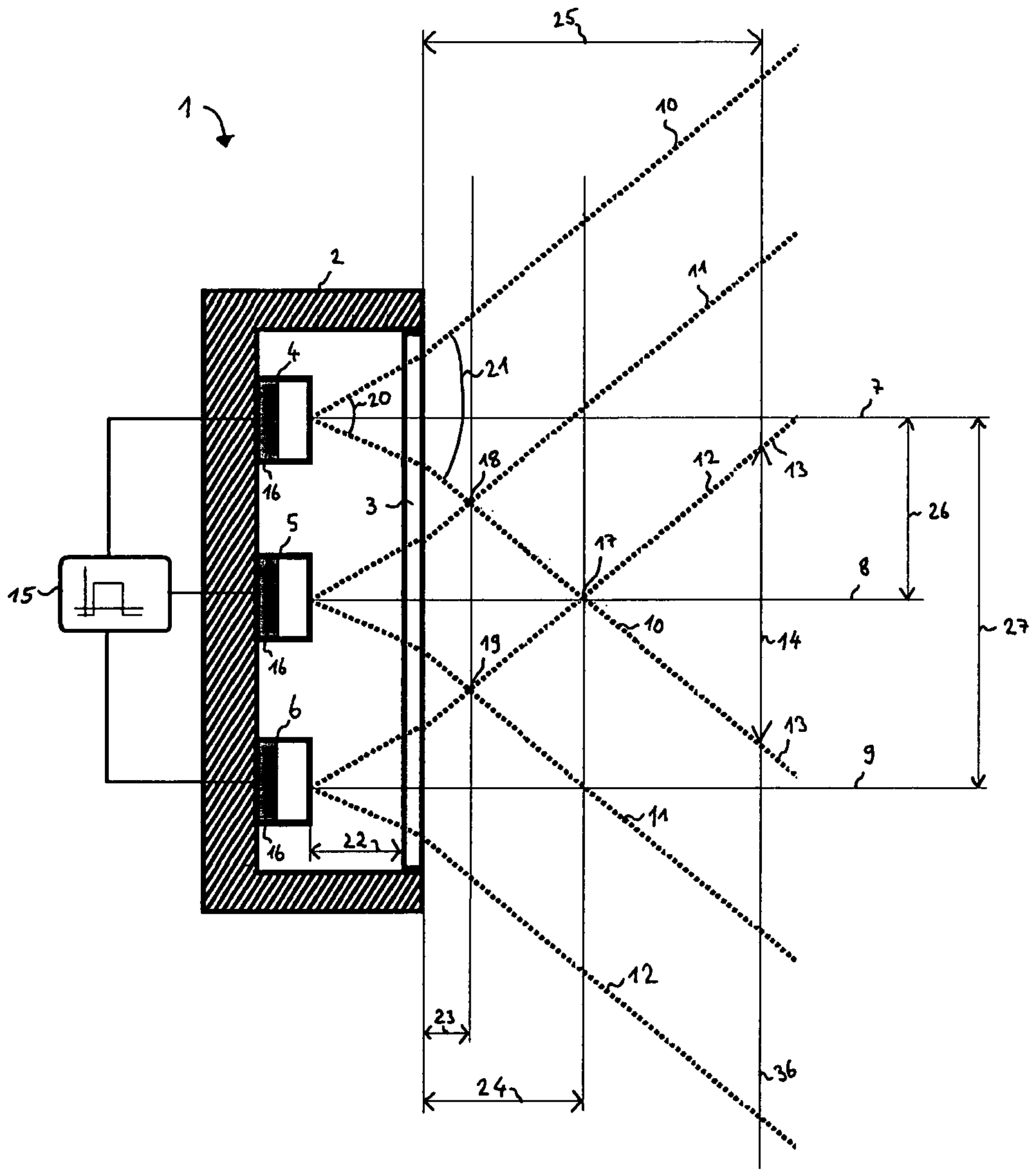
1 zeigt einen Querschnitt eines erfindungsgemäßen Strahlers, -
2 zeigt ein Diagramm einer Intensitätsverteilung in einer Querrichtung senkrecht zu einer optischen Achse des Strahlers, und -
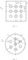
3 und4 zeigen Draufsichten von zwei Ausführungsformen des Strahlers.
-
1 shows a cross-section of a radiator according to the invention, -
2 shows a diagram of an intensity distribution in a transverse direction perpendicular to an optical axis of the radiator, and -
3 and4 show top views of two embodiments of the radiator.
Die Strahlungseinheiten 4, 5, 6 sind innerhalb eines Gehäuses 2 derart angeordnet, dass ihre optischen Achsen 7, 8, 9 parallel sind und die Strahlungseinheiten 4, 5, 6 in der gleichen Richtung orientiert sind. Die Strahlungseinheiten 4, 5, 6 sind in einer transversalen Richtung zu den optischen Achsen 7, 8, 9 benachbart zueinander in einer Reihe und in der Reihenfolge der ersten 4, der zweiten 5 und der dritten 6 Strahlungseinheit angeordnet. Das Gehäuse 2 weist ein Fenster 3 auf, welches derart angeordnet ist, dass alle Strahlungskegel 10, 11, 12 durch das Fenster 3 passieren können und das Fenster 3 einen Abstand 22 zu den Strahlungseinheiten 4, 5, 6 hat. Das Fenster 3 ist senkrecht zu den optischen Achsen 7, 8, 9 angeordnet, aber andere Anordnungen sind auch denkbar. Es ist bevorzugt, dass das Gehäuse 2 die Strahlungseinheiten 4, 5, 6 einkapselt und das Fenster 3 das einzige Teil des Gehäuses 2 ist, wo die elektromagnetische Strahlung durch passieren kann. Der Strahler 1 weist weiterhin einen Triggergenerator 15 auf, der verwendet werden kann, die Strahlungseinheiten 4, 5, 6 derart zu steuern, dass sie die elektromagnetische Strahlung simultan emittieren.The
Der Abstand 26 zwischen benachbarten Strahlungseinheiten 4, 5 und 5, 6 ist derart gewählt, dass die benachbarten Strahlungseinheiten 4, 5 und 5, 6 thermisch entkoppelt sind, so dass jede Strahlungseinheit nicht aufgrund von Wärmeemission von benachbarten Einheiten thermisch beeinflusst ist. Dies bedeutet, dass im Wesentlichen keine Wärme zu jeder Strahlungseinheit von den benachbarten Strahlungseinheiten übertragen wird.The
Die Strahlungskegel 10, 11, 12 definieren einen Beleuchtungsbereich 13 als den Bereich, wo alle Beleuchtungskegel 10, 11, 12 überlappen. Es ist bevorzugt, dass ein zu beleuchtendes Objekt innerhalb des Beleuchtungsbereichs 13 angeordnet ist, da dies der Bereich mit der höchsten Intensität ist. Der Beleuchtungsbereich 13 hat die Form eines Kegels und weist einen Beleuchtungsursprung 17 auf, der die Spitze des Kegels ist und einen Abstand 24 zu dem Fenster 3 hat. Der Beleuchtungsursprung 17 ist der naheste Punkt des Beleuchtungsbereichs 13 zu den Strahlungseinheiten 4, 5, 6 und erfindungsgemäß ist das Fenster 3 zwischen den Strahlungseinheiten 4, 5, 6 und dem Beleuchtungsursprung 17 angeordnet. Der genaue Ort des Beleuchtungsursprungs 17 hängt von der Strahldivergenz der Strahlungskegel 10, 11, 12 und des Abstands 27 zwischen den äußersten Strahlungseinheiten ab. Durch Erhöhen der Anzahl der Strahlungseinheiten erhöht sich der Abstand zwischen den äußersten Strahlungseinheiten 4, 6 und dadurch wird der Beleuchtungsursprung 17 von den Strahlungseinheiten weg bewegt, während sich die Intensität in dem Beleuchtungsbereich 13 erhöht. Durch Erhöhen der Anzahl der Strahlungseinheiten ist es vorteilhaft erreicht, dass Objekte weiter weg von den Strahlungseinheiten mit einer für eine genaue Abstandsmessung ausreichenden Intensität beleuchtet werden können.The
Wie es aus
Das Fenster 3 gemäß
Wie es aus
In der Ausführungsform gemäß
In der Ausführungsform gemäß
Die Strahlungseinheiten 4, 5, 6, 35 können beispielsweise Diodenlaser sein, die die elektromagnetische Strahlung im infraroten Wellenlängenbereich emittieren.The
Im Folgenden ist die Erfindung anhand eines Beispiels erläutert.In the following, the invention is explained using an example.
Ein erfinderischer Strahler 1 zum Beleuchten eines Objekts mit einer vorherbestimmten Intensität weist von sechs bis 124 Strahlungseinheiten 4, 5, 6, 35 des Typs Triple Stack, 75 W, 905 nm auf. Die Strahlungseinheiten 4, 5, 6, 35 können elektromagnetische Strahlung in Form eines divergierenden Strahlungskegels 10, 11, 12 emittieren, der um die optische Achse 7, 8, 9 jeder Strahlungseinheit 4, 5, 6, 35 angeordnet ist. Die Strahlungseinheiten 4, 5, 6, 35 sind derart angeordnet, dass die optischen Achsen 7, 8, 9 im Wesentlichen parallel sind und die Strahlungskegel 10, 11, 12 in der gleichen Richtung orientiert sind. Die Strahlungseinheiten 4, 5, 6, 35 sind transversal zu den optischen Achsen 7, 8, 9 in einer Bienenwabenstruktur, oder äquivalent in einem hexagonalen Raster, angeordnet, wobei jeder Abstand 26 einer Strahlungseinheit zu einer benachbarten Einheit gleich ist und von 5 mm bis 30 mm reicht. Die Strahlungseinheiten 4, 5, 6, 35 können betrieben werden, dass sie die elektromagnetische Strahlung simultan emittieren, wobei die elektromagnetische Strahlung in Lichtpulsen mit einer Dauer in der Größenordnung von Nanosekunden emittiert wird. Die Strahlungseinheiten 4, 5, 6, 35 sind in einem Gehäuse 2 angeordnet, das ein Fenster 3 aufweist, das transparent für die elektromagnetische Strahlung ist und das einzige Teil des Gehäuses ist, wo die elektromagnetische Strahlung durch passieren kann. Das Fenster 3 ist derart angeordnet, dass alle Strahlungskegel 10, 11, 12 durch passieren können. Der Abstand 22 zwischen dem Fenster 3 und den Strahlungseinheiten 4, 5, 6, 35 ist von 5 mm bis 30 mm. Die Pulsenergie jeder Strahlungseinheit 4, 5, 6, 35 auf der gegenüberliegenden Seite des Fensters 3 zu den Lasereinheiten 4, 5, 6, 35 ist zwischen 100 nJ und 500 nJ. Das Fenster 3 ist ein optischer Diffusor, welcher den Strahldivergenzwinkel 21 nach dem Fenster 3 auf einen Wert von 40° bis 80° erhöht. Ein Objekt, welches in einem Abstand zwischen 0,5 m und 20 m angeordnet ist, kann mit dem Strahler 3 derart beleuchtet werden, dass die Intensität ausreichend für eine genaue Abstandsmessung ist. Es ist vorteilhaft ausreichend Luftkühlung für den Strahler 1 zu verwenden.An inventive radiator 1 for illuminating an object with a predetermined intensity comprises from six to 124
In einem anderen denkbaren Beispiel können vier oder fünf Strahlungseinheiten 4, 5, 6, 35 verwendet werden, die beispielsweise auf einem Rechteck oder auf einem Kreis angeordnet sind.In another conceivable example, four or five
BezugszeichenlisteList of reference symbols
- 11
- StrahlerSpotlights
- 22
- GehäuseHousing
- 33
- FensterWindow
- 44
- erste Strahlungseinheitfirst radiation unit
- 55
- zweite Strahlungseinheitsecond radiation unit
- 66
- dritte Strahlungseinheitthird radiation unit
- 77
- erste optische Achsefirst optical axis
- 88th
- zweite optische Achsesecond optical axis
- 99
- dritte optische Achsethird optical axis
- 1010
- erster Strahlungskegelfirst radiation cone
- 1111
- zweiter Strahlungskegelsecond radiation cone
- 1212
- dritter Strahlungskegelthird radiation cone
- 1313
- BeleuchtungsbereichLighting area
- 1414
- Breite des Beleuchtungsbereich im Querschnitt 36Width of the lighting area in cross section 36
- 1515
- TriggergeneratorTrigger generator
- 1616
- PumpquellePump source
- 1717
- BeleuchtungsursprungLighting origin
- 1818
- erster Schnittpunktfirst intersection
- 1919
- zweiter Schnittpunktsecond intersection point
- 2020
- ursprünglicher Strahldivergenzwinkeloriginal beam divergence angle
- 2121
- modifizierter Strahldivergenzwinkelmodified beam divergence angle
- 2222
- Abstand Strahlungseinheit - FensterDistance radiation unit - window
- 2323
- Abstand Fenster - erster SchnittpunktDistance window - first intersection point
- 2424
- Abstand Fenster - BeleuchtungsursprungDistance window - lighting source
- 2525
- Abstand Fenster - Querschnitt 36Distance window - cross section 36
- 2626
- Abstand zwischen benachbarten StrahlungseinheitenDistance between adjacent radiation units
- 2727
- Abstand zwischen den äußersten StrahlungseinheitenDistance between the outermost radiation units
- 2828
- Intensitätintensity
- 2929
- QuerrichtungTransverse direction
- 3030
- Intensität I1 Intensity I 1
- 3131
- Intensität I2 Intensity I 2
- 3232
- Intensität I3 Intensity I 3
- 3333
- erstes Rasterfirst grid
- 3434
- zweites Rastersecond grid
- 3535
- StrahlungseinheitRadiation unit
- 3636
- Querschnittcross-section
Claims (12)
Priority Applications (2)
| Application Number | Priority Date | Filing Date | Title |
|---|---|---|---|
| DE102012112644.5A DE102012112644B4 (en) | 2012-12-19 | 2012-12-19 | Spotlight for illuminating an object and distance measuring device with the spotlight |
| PCT/EP2013/077322 WO2014096157A1 (en) | 2012-12-19 | 2013-12-19 | Radiator for illuminating an object and distance measuring device with the radiator |
Applications Claiming Priority (1)
| Application Number | Priority Date | Filing Date | Title |
|---|---|---|---|
| DE102012112644.5A DE102012112644B4 (en) | 2012-12-19 | 2012-12-19 | Spotlight for illuminating an object and distance measuring device with the spotlight |
Publications (2)
| Publication Number | Publication Date |
|---|---|
| DE102012112644A1 DE102012112644A1 (en) | 2014-06-26 |
| DE102012112644B4 true DE102012112644B4 (en) | 2024-05-16 |
Family
ID=50878428
Family Applications (1)
| Application Number | Title | Priority Date | Filing Date |
|---|---|---|---|
| DE102012112644.5A Expired - Fee Related DE102012112644B4 (en) | 2012-12-19 | 2012-12-19 | Spotlight for illuminating an object and distance measuring device with the spotlight |
Country Status (2)
| Country | Link |
|---|---|
| DE (1) | DE102012112644B4 (en) |
| WO (1) | WO2014096157A1 (en) |
Families Citing this family (6)
| Publication number | Priority date | Publication date | Assignee | Title |
|---|---|---|---|---|
| JP6250080B2 (en) * | 2016-02-25 | 2017-12-20 | 三菱重工業株式会社 | Laser radar device and traveling body |
| DE102017121346A1 (en) | 2016-09-15 | 2018-03-15 | Osram Opto Semiconductors Gmbh | Measuring system, use of at least one individually operable light-emitting diode lighting unit as a transmitter unit in a measuring system, method for operating a measuring system and illumination source with a measuring system |
| CN107632297B (en) * | 2017-08-25 | 2019-08-06 | 中国科学院西安光学精密机械研究所 | An ultra-light laser irradiator |
| FR3112851B1 (en) * | 2020-07-24 | 2022-09-09 | Univ Aix Marseille | Device and method for optical position detection |
| US12339113B2 (en) | 2022-06-30 | 2025-06-24 | Ge Infrastructure Technology Llc | Apparatus and method for transmitting radiation to a rotating component |
| US20240003679A1 (en) * | 2022-06-30 | 2024-01-04 | General Electric Company | Apparatus and method for detecting radiation deflected from a rotating component |
Citations (4)
| Publication number | Priority date | Publication date | Assignee | Title |
|---|---|---|---|---|
| DE102006025020A1 (en) * | 2006-05-26 | 2007-11-29 | Pmd Technologies Gmbh | Time of flight lighting for illumination to capture three dimensional scenery, has illuminant and is combined with signal lighting and surface lighting |
| WO2010149593A1 (en) | 2009-06-22 | 2010-12-29 | Toyota Motor Europe Nv/Sa | Pulsed light optical rangefinder |
| DE102009045553A1 (en) * | 2009-10-12 | 2011-04-14 | Ifm Electronic Gmbh | Light-time measurement system has receiving unit, receiving-pixel array and corresponding receiving optics which forms receiving space angle |
| EP2354635A1 (en) * | 2010-01-28 | 2011-08-10 | Franz Sill GmbH | LED facade spotlight |
Family Cites Families (2)
| Publication number | Priority date | Publication date | Assignee | Title |
|---|---|---|---|---|
| JP2000310679A (en) * | 1999-02-24 | 2000-11-07 | Denso Corp | Semiconductor light emitting device and distance measuring device |
| WO2009153699A1 (en) * | 2008-06-18 | 2009-12-23 | Philips Intellectual Property & Standards Gmbh | Driver assistance system |
-
2012
- 2012-12-19 DE DE102012112644.5A patent/DE102012112644B4/en not_active Expired - Fee Related
-
2013
- 2013-12-19 WO PCT/EP2013/077322 patent/WO2014096157A1/en not_active Ceased
Patent Citations (4)
| Publication number | Priority date | Publication date | Assignee | Title |
|---|---|---|---|---|
| DE102006025020A1 (en) * | 2006-05-26 | 2007-11-29 | Pmd Technologies Gmbh | Time of flight lighting for illumination to capture three dimensional scenery, has illuminant and is combined with signal lighting and surface lighting |
| WO2010149593A1 (en) | 2009-06-22 | 2010-12-29 | Toyota Motor Europe Nv/Sa | Pulsed light optical rangefinder |
| DE102009045553A1 (en) * | 2009-10-12 | 2011-04-14 | Ifm Electronic Gmbh | Light-time measurement system has receiving unit, receiving-pixel array and corresponding receiving optics which forms receiving space angle |
| EP2354635A1 (en) * | 2010-01-28 | 2011-08-10 | Franz Sill GmbH | LED facade spotlight |
Also Published As
| Publication number | Publication date |
|---|---|
| WO2014096157A1 (en) | 2014-06-26 |
| DE102012112644A1 (en) | 2014-06-26 |
Similar Documents
| Publication | Publication Date | Title |
|---|---|---|
| DE102012112644B4 (en) | Spotlight for illuminating an object and distance measuring device with the spotlight | |
| DE102010031199B4 (en) | Beam shaping apparatus and method | |
| DE102018203352B4 (en) | Transmitter unit and LIDAR device for scanning a scanning area | |
| DE102011115141B4 (en) | Solar Simulator | |
| WO2012130495A1 (en) | Optical element and radiation-emitting device comprising such an optical element | |
| DE102019118600A1 (en) | Phosphor light source for CLS or Multipoint | |
| DE10049557A1 (en) | Device for converting the intensity distribution of a laser beam and device and method for generating a laser beam with an intensity which continuously declines from one side of the beam to the other along an axis | |
| DE19532877A1 (en) | Device for linear lighting of sheet material, such as. B. banknotes or securities | |
| EP3121510B1 (en) | Adaptor lens | |
| WO2015075188A1 (en) | Optical element and lighting device with an optical element | |
| CH715534A1 (en) | Optics and table lamp. | |
| EP4451019A2 (en) | Light | |
| EP2249076A1 (en) | Street lamp with punctiform light sources, in particular LED light | |
| EP3461687B1 (en) | Light guide arrangement for a motor vehicle light and motor vehicle light provided with such a light guide arrangement | |
| EP2317215B1 (en) | Light with at least one LED | |
| WO2009003618A1 (en) | Device for producing laser radiation | |
| EP1279988B1 (en) | Laser illumination device for illuminating a line or a strip-like area | |
| DE102017107821A1 (en) | ARRANGEMENT WITH AT LEAST TWO LASER DIODES AND DIFFACTIVE ELEMENT | |
| EP3671026A1 (en) | Luminaire | |
| EP3283820A1 (en) | Optical system, and assembly for emitting light | |
| DE102004045914B4 (en) | Method and device for superimposing beams | |
| DE10204939A1 (en) | Device for generating flat parallel light has two adjacent lenses in plane perpendicular to main radiation direction, illuminated in 2-D by one of two point sources, parallel in at least one dimension | |
| DE102022118316B4 (en) | Lighting system for illuminating a scene, detection system, method and lidar system | |
| EP2541133A2 (en) | Spotlight | |
| EP2924343A1 (en) | Led light with refractive optics for mixing light |
Legal Events
| Date | Code | Title | Description |
|---|---|---|---|
| R012 | Request for examination validly filed | ||
| R016 | Response to examination communication | ||
| R082 | Change of representative |
Representative=s name: GRUENECKER PATENT- UND RECHTSANWAELTE PARTG MB, DE |
|
| R018 | Grant decision by examination section/examining division | ||
| R020 | Patent grant now final | ||
| R119 | Application deemed withdrawn, or ip right lapsed, due to non-payment of renewal fee |