DE102011117631A1 - Wind turbine for converting renewable energy of wind in electrical energy, has vertical rotational axis, rotatably mounted base ring and double-curved spatial network grid made from partially aerodynamically effective struts - Google Patents
Wind turbine for converting renewable energy of wind in electrical energy, has vertical rotational axis, rotatably mounted base ring and double-curved spatial network grid made from partially aerodynamically effective struts Download PDFInfo
- Publication number
- DE102011117631A1 DE102011117631A1 DE102011117631A DE102011117631A DE102011117631A1 DE 102011117631 A1 DE102011117631 A1 DE 102011117631A1 DE 102011117631 A DE102011117631 A DE 102011117631A DE 102011117631 A DE102011117631 A DE 102011117631A DE 102011117631 A1 DE102011117631 A1 DE 102011117631A1
- Authority
- DE
- Germany
- Prior art keywords
- wind
- struts
- base ring
- rotatably mounted
- partially
- Prior art date
- Legal status (The legal status is an assumption and is not a legal conclusion. Google has not performed a legal analysis and makes no representation as to the accuracy of the status listed.)
- Ceased
Links
- 238000010276 construction Methods 0.000 description 7
- 238000000605 extraction Methods 0.000 description 6
- XLYOFNOQVPJJNP-UHFFFAOYSA-N water Substances O XLYOFNOQVPJJNP-UHFFFAOYSA-N 0.000 description 5
- 238000005452 bending Methods 0.000 description 4
- 238000004519 manufacturing process Methods 0.000 description 4
- 238000009434 installation Methods 0.000 description 3
- 238000006243 chemical reaction Methods 0.000 description 2
- 238000007654 immersion Methods 0.000 description 2
- 238000000034 method Methods 0.000 description 2
- GVGLGOZIDCSQPN-PVHGPHFFSA-N Heroin Chemical compound O([C@H]1[C@H](C=C[C@H]23)OC(C)=O)C4=C5[C@@]12CCN(C)[C@@H]3CC5=CC=C4OC(C)=O GVGLGOZIDCSQPN-PVHGPHFFSA-N 0.000 description 1
- 238000001125 extrusion Methods 0.000 description 1
- 230000002349 favourable effect Effects 0.000 description 1
- 238000007667 floating Methods 0.000 description 1
- 238000005339 levitation Methods 0.000 description 1
- 238000012423 maintenance Methods 0.000 description 1
- 238000009401 outcrossing Methods 0.000 description 1
- 238000010248 power generation Methods 0.000 description 1
- 230000001141 propulsive effect Effects 0.000 description 1
- 230000001172 regenerating effect Effects 0.000 description 1
Images


Classifications
-
- F—MECHANICAL ENGINEERING; LIGHTING; HEATING; WEAPONS; BLASTING
- F03—MACHINES OR ENGINES FOR LIQUIDS; WIND, SPRING, OR WEIGHT MOTORS; PRODUCING MECHANICAL POWER OR A REACTIVE PROPULSIVE THRUST, NOT OTHERWISE PROVIDED FOR
- F03D—WIND MOTORS
- F03D3/00—Wind motors with rotation axis substantially perpendicular to the air flow entering the rotor
- F03D3/06—Rotors
- F03D3/061—Rotors characterised by their aerodynamic shape, e.g. aerofoil profiles
-
- F—MECHANICAL ENGINEERING; LIGHTING; HEATING; WEAPONS; BLASTING
- F03—MACHINES OR ENGINES FOR LIQUIDS; WIND, SPRING, OR WEIGHT MOTORS; PRODUCING MECHANICAL POWER OR A REACTIVE PROPULSIVE THRUST, NOT OTHERWISE PROVIDED FOR
- F03D—WIND MOTORS
- F03D3/00—Wind motors with rotation axis substantially perpendicular to the air flow entering the rotor
- F03D3/06—Rotors
- F03D3/062—Rotors characterised by their construction elements
-
- F—MECHANICAL ENGINEERING; LIGHTING; HEATING; WEAPONS; BLASTING
- F03—MACHINES OR ENGINES FOR LIQUIDS; WIND, SPRING, OR WEIGHT MOTORS; PRODUCING MECHANICAL POWER OR A REACTIVE PROPULSIVE THRUST, NOT OTHERWISE PROVIDED FOR
- F03D—WIND MOTORS
- F03D5/00—Other wind motors
- F03D5/04—Other wind motors the wind-engaging parts being attached to carriages running on tracks or the like
-
- F—MECHANICAL ENGINEERING; LIGHTING; HEATING; WEAPONS; BLASTING
- F05—INDEXING SCHEMES RELATING TO ENGINES OR PUMPS IN VARIOUS SUBCLASSES OF CLASSES F01-F04
- F05B—INDEXING SCHEME RELATING TO WIND, SPRING, WEIGHT, INERTIA OR LIKE MOTORS, TO MACHINES OR ENGINES FOR LIQUIDS COVERED BY SUBCLASSES F03B, F03D AND F03G
- F05B2240/00—Components
- F05B2240/90—Mounting on supporting structures or systems
- F05B2240/91—Mounting on supporting structures or systems on a stationary structure
- F05B2240/912—Mounting on supporting structures or systems on a stationary structure on a tower
- F05B2240/9121—Mounting on supporting structures or systems on a stationary structure on a tower on a lattice tower
-
- F—MECHANICAL ENGINEERING; LIGHTING; HEATING; WEAPONS; BLASTING
- F05—INDEXING SCHEMES RELATING TO ENGINES OR PUMPS IN VARIOUS SUBCLASSES OF CLASSES F01-F04
- F05B—INDEXING SCHEME RELATING TO WIND, SPRING, WEIGHT, INERTIA OR LIKE MOTORS, TO MACHINES OR ENGINES FOR LIQUIDS COVERED BY SUBCLASSES F03B, F03D AND F03G
- F05B2240/00—Components
- F05B2240/90—Mounting on supporting structures or systems
- F05B2240/94—Mounting on supporting structures or systems on a movable wheeled structure
-
- F—MECHANICAL ENGINEERING; LIGHTING; HEATING; WEAPONS; BLASTING
- F05—INDEXING SCHEMES RELATING TO ENGINES OR PUMPS IN VARIOUS SUBCLASSES OF CLASSES F01-F04
- F05B—INDEXING SCHEME RELATING TO WIND, SPRING, WEIGHT, INERTIA OR LIKE MOTORS, TO MACHINES OR ENGINES FOR LIQUIDS COVERED BY SUBCLASSES F03B, F03D AND F03G
- F05B2250/00—Geometry
- F05B2250/10—Geometry two-dimensional
- F05B2250/11—Geometry two-dimensional triangular
-
- F—MECHANICAL ENGINEERING; LIGHTING; HEATING; WEAPONS; BLASTING
- F05—INDEXING SCHEMES RELATING TO ENGINES OR PUMPS IN VARIOUS SUBCLASSES OF CLASSES F01-F04
- F05B—INDEXING SCHEME RELATING TO WIND, SPRING, WEIGHT, INERTIA OR LIKE MOTORS, TO MACHINES OR ENGINES FOR LIQUIDS COVERED BY SUBCLASSES F03B, F03D AND F03G
- F05B2250/00—Geometry
- F05B2250/70—Shape
- F05B2250/71—Shape curved
-
- Y—GENERAL TAGGING OF NEW TECHNOLOGICAL DEVELOPMENTS; GENERAL TAGGING OF CROSS-SECTIONAL TECHNOLOGIES SPANNING OVER SEVERAL SECTIONS OF THE IPC; TECHNICAL SUBJECTS COVERED BY FORMER USPC CROSS-REFERENCE ART COLLECTIONS [XRACs] AND DIGESTS
- Y02—TECHNOLOGIES OR APPLICATIONS FOR MITIGATION OR ADAPTATION AGAINST CLIMATE CHANGE
- Y02E—REDUCTION OF GREENHOUSE GAS [GHG] EMISSIONS, RELATED TO ENERGY GENERATION, TRANSMISSION OR DISTRIBUTION
- Y02E10/00—Energy generation through renewable energy sources
- Y02E10/70—Wind energy
- Y02E10/728—Onshore wind turbines
-
- Y—GENERAL TAGGING OF NEW TECHNOLOGICAL DEVELOPMENTS; GENERAL TAGGING OF CROSS-SECTIONAL TECHNOLOGIES SPANNING OVER SEVERAL SECTIONS OF THE IPC; TECHNICAL SUBJECTS COVERED BY FORMER USPC CROSS-REFERENCE ART COLLECTIONS [XRACs] AND DIGESTS
- Y02—TECHNOLOGIES OR APPLICATIONS FOR MITIGATION OR ADAPTATION AGAINST CLIMATE CHANGE
- Y02E—REDUCTION OF GREENHOUSE GAS [GHG] EMISSIONS, RELATED TO ENERGY GENERATION, TRANSMISSION OR DISTRIBUTION
- Y02E10/00—Energy generation through renewable energy sources
- Y02E10/70—Wind energy
- Y02E10/74—Wind turbines with rotation axis perpendicular to the wind direction
Landscapes
- Engineering & Computer Science (AREA)
- Life Sciences & Earth Sciences (AREA)
- Sustainable Development (AREA)
- Sustainable Energy (AREA)
- Chemical & Material Sciences (AREA)
- Combustion & Propulsion (AREA)
- Mechanical Engineering (AREA)
- General Engineering & Computer Science (AREA)
- Physics & Mathematics (AREA)
- Fluid Mechanics (AREA)
- Aviation & Aerospace Engineering (AREA)
- Wind Motors (AREA)
Abstract
Description
Windkraftanlagen wandeln die regenerative Energie des Windes in elektrische Energie um. Aufgrund der höheren und stetigeren Windgeschwindigkeit in größeren Höhen sind die Stromentstehungskosten in der Regel um so kleiner je höher und größer die Anlage ist. Ab einer bestimmten Bauhöhe steigt jedoch bei den bekannten Horizontalläufern der Aufwand für Transport und Montage stark an, da die einzelnen Bauelemente in Ihrem Gewicht oder Höhe an die Grenzen der Transport- und Montagemöglichkeiten stoßen. Auch die Fliehkräfte innerhalb der Rotorblätter sowie deren Belastungen aus der Gewichtskraft, welche auf die Rotorblätter je nach Stellung in unterschiedliche Richtungen wirkt, lässt eine weitere Größenzunahme nur bedingt zu. Die bekannten Bauweisen für Vertikalläufer sind kaum geeignet diese Windkraftanlagen in sehr großer Größe auszuführen. Generell gilt das der konstruktive Aufwand für das Tragwerk, welches die großen horizontalen Lasten zum Boden ableiten muss, mit steigender Höhe überproportional wächst.Wind turbines convert the regenerative energy of the wind into electrical energy. Due to the higher and more constant wind speed at higher altitudes, the power generation costs are usually the smaller the higher and larger the system is. From a certain height, however, the cost of transport and installation increases greatly in the known horizontal runners, since the individual components in their weight or height reach the limits of transport and installation options. The centrifugal forces within the rotor blades and their loads from the weight, which acts on the rotor blades depending on the position in different directions, allows a further increase in size only limited. The known construction methods for vertical runners are hardly suitable to carry out these wind turbines in very large size. In general, this applies to the structural complexity of the structure, which must divert the large horizontal loads to the ground, disproportionately grows with increasing height.
Ziel der Erfindung ist es eine Windkraftanlage zu entwickeln, deren konstruktiver Aufwand möglichst gering ist, die einfach in gut zu transportierenden Einzelteilen zu fertigen ist, große bauliche Höhen ermöglicht und dabei einen hinreichend guten Wirkungsgrad erzielt. Der Anteil der mechanisch beanspruchten und damit wartungsintensiven Teile wie Lager, Getriebe etc. soll minimiert werden. Die dynamischen Lastwechsel sollen möglichst gering sein.The aim of the invention is to develop a wind turbine whose design complexity is as low as possible, which is easy to manufacture in well-transportable items, large structural heights and thereby achieves a sufficiently good efficiency. The proportion of mechanically stressed and thus maintenance-intensive parts such as bearings, gears, etc. should be minimized. The dynamic load changes should be as low as possible.
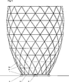
Erreicht wird dies durch eine Windkraftanlage mit folgenden Aufbau: Ein unterer, auf einem kreisrunden Auflager (
Die Form dieses Netzgittertragwerkes kann zylindrisch sein. Es ist jedoch vorteilhaft es zweifach gekrümmt auszubilden. Dies hat folgende Vorteile: Erstens: Die Lastabtragung eines zweifach gekrümmten Netzgittertragwerks ist effizienter als bei einfacher Krümmung. Zweitens: Der Durchmesser der Struktur in größerer Höhe ist größer als der vom Basisring. Damit ist die Geschwindigkeit am Basisring kleiner als im oberen Teil was günstig für die Reibungsverluste der Lagerung bzw. die Windausbeute ist. Die Querschnittsform der Gesamtstruktur kann so gebildet sein, das in Ähnlichkeit zum vorherrschendem Windprofil der Durchmesser mit der Höhe zunächst stark, später weniger stark zunimmt. Hierdurch kann erreicht werden das das Verhältnis von lokaler Windgeschwindigkeit zur lokalen Rotationsgeschwindigkeit auch bei großen Bauhöhen von über 100 m annähernd gleich bleibt.The shape of this mesh support structure can be cylindrical. However, it is advantageous to form it twice curved. This has the following advantages: Firstly, the load transfer of a double-curved mesh structure is more efficient than with simple curvature. Second, the diameter of the structure at a greater height is greater than that of the base ring. Thus, the speed at the base ring is smaller than in the upper part which is favorable for the frictional losses of storage or the wind yield. The cross-sectional shape of the overall structure may be formed so that, in similarity to the prevailing wind profile, the diameter first increases strongly, later less strongly. In this way, it can be achieved that the ratio of local wind speed to local rotational speed remains approximately the same even for large heights of more than 100 m.
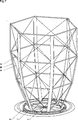
Der untere Ring muss sowohl Kräfte aus dem Netzgitter aufnehmen und ableiten als auch die Rotationsbewegung ermöglichen. Hierbei sind verschiedene Ausführungsvarianten denkbar: Eine Lagerung auf Rollen bzw. Schienen erscheint zwar möglich jedoch recht aufwendig und wartungsintensiv. Eine Lagerung durch ein magnetisches Feld ist zwar auch aufwendig, jedoch bietet dies die Vorteile von sehr geringen Reibungsverlusten und eine nahezu wartungsfreie Konstruktion. In Bezug auf Herstellungskosten am günstigsten erscheint es den Ring als Schwimmkörper auszubilden und diesen z. B. auf Wasser schwimmen zu lassen. Die Windlasten verursachen dabei eine gewisse Schrägstellung des Systems und damit ein unterschiedliches Eintauchen des Ringes je nach anliegenden Kräften. Die Auftriebskraft bzw. Gewichtskraft kann somit eine Reaktionskraft auf das durch die Windbelastung erzeugte Moment bilden. Dabei muss jedoch die Horizontalkraft über geeignete Auflager abgeleitet werden. Dies kann vorzugsweise über einen zentralen Drehpunkt (
Bei Ausbildung des Basisringes als drehbarer Schwimmkörper entstehen gerade bei höheren Geschwindigkeiten Verluste durch den Strömungswiderstand. Der Schwimmkörper sollte also idealerweise als Rotationskörper mit glatter Oberfläche gebildet werden, dessen mit dem Wasser in Berührung kommende Oberfläche möglichst gering ist. Um die Kontaktfläche von Schwimmkörper und Wasser zu verringern kann die Querschnittsform des Ringes abgeflacht und ein Luftkissen unter dem Schwimmkörper erzeugt werden indem nach unten geöffnete Kammern (
Die Energieumwandlung der Windenergie in elektrische oder anderweitig nutzbare mechanische Energie erfolgt entsprechend den bekannten Methoden am günstigsten direkt am Basisring. Eine Installation von Getriebe, Steuereinheiten oder Generatoren in großer Höhe ist damit nicht notwendig was sehr vorteilhaft ist. Ein am zentralen Mittelpunkt angeordneter Generator mit entsprechendem Getriebe ist zwar prinzipiell möglich, die höhere Geschwindigkeit des Basisrings lässt jedoch ein Abgreifen der Energie am Basisring wirtschaftlicher erscheinen. Hierfür gibt es eine Vielzahl von möglichen Ausführungsvarianten. So können Räder oder auf Zahnschienen laufende Zahnräder an dem Basisring ansetzten und so einen üblichen Generator antreiben. Sinnvoll erscheint die Ausbildung von mehreren solcher Energieentnahmeeinrichtungen (
Bei einer magnetischen Lagerung des Basisringes ergibt sich die Möglichkeit direkt im magnetsichen Auflager die mechanische Rotationsenergie in elektrische Energie umzuwandeln ähnlich oder gleich dem bekannten Verfahren einer Magnetschwebebahn im Bremsmodus.In the case of a magnetic bearing of the base ring, the possibility arises directly in the magnetic bearing that converts the mechanical rotational energy into electrical energy, similar or identical to the known method of a magnetic levitation train in braking mode.
Das Netz aus Streben (
Bei sehr hohen und relativ schlanken Anlagen kann es sinnvoll sein auf einer oder mehreren Ebenen radiale vorgespannte Seile anzuordnen, die sich auf der Zentrumsachse treffen. Dieses Bauprinzip, welches bei Speichenrädern verwendet wird, erhöht recht effizient die räumliche Steifheit des Netzgitters.For very tall and relatively slender plants, it may be useful to arrange radial prestressed ropes on one or more levels that meet on the center axis. This construction principle, which is used with spoked wheels, increases quite effectively the spatial rigidity of the net grid.
BezugszeichenlisteLIST OF REFERENCE NUMBERS
- 11
- drehbar gelagerter Ringrotatably mounted ring
- 22
- Strebestrut
- 2a2a
- horizontale Strebehorizontal strut
- 2b2 B
- stehende Strebestanding strut
- 2c2c
- zugbelastete Strebetensioned strut
- 33
- ringförmiges Auflagerannular support
- 44
- EnergieentnahmeeinrichtungEnergy extraction device
- 55
- zentraler Drehpunktcentral pivot point
- 66
- zugbeanspruchtes Elementtensile stressed element
- 77
- Auslegerarmboom
- 88th
- Dammdam
- 99
- SchotteScot
- 1010
- nach unten geöffnete Kammerdownwardly open chamber
Claims (1)
Priority Applications (1)
| Application Number | Priority Date | Filing Date | Title |
|---|---|---|---|
| DE102011117631A DE102011117631A1 (en) | 2011-11-05 | 2011-11-05 | Wind turbine for converting renewable energy of wind in electrical energy, has vertical rotational axis, rotatably mounted base ring and double-curved spatial network grid made from partially aerodynamically effective struts |
Applications Claiming Priority (1)
| Application Number | Priority Date | Filing Date | Title |
|---|---|---|---|
| DE102011117631A DE102011117631A1 (en) | 2011-11-05 | 2011-11-05 | Wind turbine for converting renewable energy of wind in electrical energy, has vertical rotational axis, rotatably mounted base ring and double-curved spatial network grid made from partially aerodynamically effective struts |
Publications (1)
| Publication Number | Publication Date |
|---|---|
| DE102011117631A1 true DE102011117631A1 (en) | 2013-05-08 |
Family
ID=48128897
Family Applications (1)
| Application Number | Title | Priority Date | Filing Date |
|---|---|---|---|
| DE102011117631A Ceased DE102011117631A1 (en) | 2011-11-05 | 2011-11-05 | Wind turbine for converting renewable energy of wind in electrical energy, has vertical rotational axis, rotatably mounted base ring and double-curved spatial network grid made from partially aerodynamically effective struts |
Country Status (1)
| Country | Link |
|---|---|
| DE (1) | DE102011117631A1 (en) |
Cited By (4)
| Publication number | Priority date | Publication date | Assignee | Title |
|---|---|---|---|---|
| DE102017002797B3 (en) | 2017-03-20 | 2018-06-28 | Friedrich Grimm | FLOW CONVERTER WITH AT LEAST ONE TURNING WING |
| DE102018114004A1 (en) * | 2018-06-12 | 2019-12-12 | Andreas Demopoulos | Wind turbine with vertical axis of rotation of the rotor and floating wind farm with several such wind turbines |
| DE102020204945A1 (en) | 2020-04-20 | 2021-10-21 | Rolf Sigmann | Wind turbine and use of the wind turbine |
| DE102020007543B3 (en) | 2020-12-08 | 2022-03-17 | Friedrich B. Grimm | WIND TURBINE WITH A VERTICAL ROTATIONAL AXIS |
-
2011
- 2011-11-05 DE DE102011117631A patent/DE102011117631A1/en not_active Ceased
Cited By (6)
| Publication number | Priority date | Publication date | Assignee | Title |
|---|---|---|---|---|
| DE102017002797B3 (en) | 2017-03-20 | 2018-06-28 | Friedrich Grimm | FLOW CONVERTER WITH AT LEAST ONE TURNING WING |
| DE102018114004A1 (en) * | 2018-06-12 | 2019-12-12 | Andreas Demopoulos | Wind turbine with vertical axis of rotation of the rotor and floating wind farm with several such wind turbines |
| US11867152B2 (en) | 2018-06-12 | 2024-01-09 | Charalampos Tassakos | Wind turbine with vertical axis of rotation of the rotor and floating wind farm comprising a plurality of such wind turbines |
| DE102020204945A1 (en) | 2020-04-20 | 2021-10-21 | Rolf Sigmann | Wind turbine and use of the wind turbine |
| DE102020007543B3 (en) | 2020-12-08 | 2022-03-17 | Friedrich B. Grimm | WIND TURBINE WITH A VERTICAL ROTATIONAL AXIS |
| WO2022122599A1 (en) | 2020-12-08 | 2022-06-16 | Friedrich Grimm | Wind power plant having a vertical rotation axis |
Similar Documents
| Publication | Publication Date | Title |
|---|---|---|
| DE102011102316A1 (en) | Multi-stage process for the erection and maintenance of wind turbines | |
| DE102015000818B3 (en) | Wind turbine tower | |
| WO2008006413A1 (en) | Wind-operated power generator | |
| EP1270848B1 (en) | Elastic rope anchoring for off-shore buildings | |
| DE102011056980A1 (en) | Wind turbine | |
| EP2171266A2 (en) | Wind turbine with additional blade-end support | |
| WO2018166939A1 (en) | Floatable offshore system for converting wind energy and/or solar energy into electric energy | |
| DE102011117631A1 (en) | Wind turbine for converting renewable energy of wind in electrical energy, has vertical rotational axis, rotatably mounted base ring and double-curved spatial network grid made from partially aerodynamically effective struts | |
| DE19846796A1 (en) | Floating wind power system, has electricity generating wind power devices attached to floating system to be as close as possible above sea surface, and symmetrical about floating system center | |
| DE102008047261A1 (en) | Device for wind power installation, is fastened to towing rope for producing electric energy by veering towing kite, where towing rope is fastened to cable winch firmly anchored with ground | |
| DE102009054608A1 (en) | Underwater production system for plants | |
| DE102012009145A1 (en) | Wind turbine with horizontal rotor shaft and with rotatable tower | |
| DE3300049A1 (en) | Wind gyro, a wind energy converter with a vertical axis for all magnitudes up to and including the 100 MW range | |
| DE102019130374A1 (en) | Photovoltaic installation on a tower | |
| AT410576B (en) | DEVICE AND METHOD FOR GENERATING ELECTRICAL ENERGY | |
| DE202019001821U1 (en) | Wind energy; Generation Modification and Efficiency System | |
| DE10332678A1 (en) | Vertical axis wind-powered energy generation plant has each wind turbine rotor blade divided into small and large sections on opposite sides of local horizontal axis | |
| DE202022104680U1 (en) | A support rod structure of a wind wheel in a wind turbine | |
| DE102010013504A1 (en) | Wind turbine for converting wind into current, has traction body deflecting strokes of lightning, where turbine comprises no rigid connection to floor and is operated at heights in which uniform wind is not swirled by obstructions | |
| DE102004001573A1 (en) | Vertical axis wind turbine has an upright array of rotor blades each located within a cell forming part of a grid | |
| EP1035325A1 (en) | Transportable wind turbine | |
| DE102005043444A1 (en) | Wind power plant has at least one macro-ring and at least three rotor blade carriers fixed to macro-ring, wherein each rotor blade carrier has number of rotor blades with horizontal and/or vertical and/or inclined local axes | |
| DE102014224083A1 (en) | Wind energy generator system and maintenance method for the wind energy generator system | |
| AT412808B (en) | Pylon | |
| DE102009013161A1 (en) | Hub-airfoil system e.g. video system and camera system, for controlling e.g. wind energy, in wind turbine, has energy convertors and energy storing device arranged under base of base body in closed housing |
Legal Events
| Date | Code | Title | Description |
|---|---|---|---|
| R012 | Request for examination validly filed | ||
| R086 | Non-binding declaration of licensing interest | ||
| R002 | Refusal decision in examination/registration proceedings | ||
| R003 | Refusal decision now final |